1
ICP Electronics Inc.
Page 1/15
LCD Module User’s Manual
A125 Ver 0.4
RS232
automatically when PC and A125 is power on and
Author:
Davis Wang
ICP Electronics Inc.
keep until PC start to display message on LCD or
Clear LCD, this is specially useful for some very
slow booting OS and could not take control the
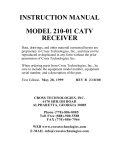
Introduction
A125 is an enhanced characters LCD display
module and be designed for PC could easily to
display message from RS232/COM port. The
maximum display text allowed is 2 lines of 16
characters, A125
Communication
following ICP Peripheral
Protocol
(Appendix
A)
to
communication with PC and provide two buttons
for to let human pressed and then pass selections
COM port when under Power On.
Features
A.
B.
C.
D.
E.
16x2 characters LCD.
2 general purpose buttons.
Backlight could be turn off by program
RS232 interface (1200, N, 8, 1)
Provide one first display page. (Auto display
SYSTEM BOOTING when A125 and PC is
power on)
or control to PC. Meanwhile, A125 also provide
one first display page (SYSTEM BOOTING)
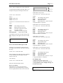
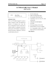
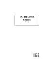
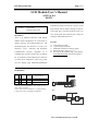
Pin Definition
VCC
Power
(+5V)
2 Rx
In
3 Tx
Out
4 GND Power
CN1 1
+5V
GROUND
5V power in
RS232 Data Input
RS232 Data Out
Ground
**The RS232 fixed 1200 Baud Rate, 8 bit, 1 stop bit, no parity
check, default ±12V Signal.
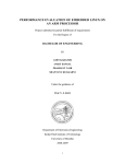
Note: If A125 want to be installed on a 5V signal transaction
(UART), please refer to Appendix B for modification.
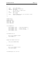
CN1
1
2
3
4
Transmit from PC to A125
Transmit from A125 to PC
A125
1
6
2
7
3
8
4
9
5
COM Port
OR
+5V
GROUND
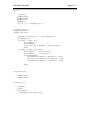
CN1
1
2
3
4
A125
JS1
Transmit from PC to A125
Transmit from A125 to PC
1
2
3
4
5
1
2
3
4
5
6
7
8
9
10
COM Port
How to Displaying Messages on LCD
6
7
8
9
10
ICP Electronics Inc.
Page 2/15
A125 is able to display most of the characters
you can find on the ASCII code table. Here is an
example to display text messages on the LCD.
Send to A125: 0x4D 0x0D
Where:
0x4D is prefix code.
0x0D is Clear LCD.
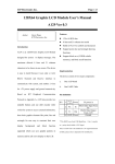
Send to A125: 0x4D 0x0C 0x00 0x03 0x49 0x43
BUTTON 0
BUTTON 1
When button 0 be pressed :
A125 send to PC : 0x53 0x05 0x00 0x01;
Where
0x53
The leading code of A125.
0x05
Report Button Status.
0x00
Button data byte 0.
0x01
Button data byte 1, the bit 0 of byte 1
respect the button 0 is pressed.
0x50
Where:
0x4D
0x0C
0x00
The Leading Code of PC.
Display Character on LCD
Characters displayed on line0
(first line on LCD)
0x03
3 characters will be displayed
0x49 0x43 0x50
ASCII codes for ICP
The LCD first clear the screen and then the text
ICP is display on the upper-left corner of LCD
like
ICP
How to Turn Off the Back Light of LCD
Sometime, if you find the back light of LCD is
too bright or not necessary, you can turn off it by
this way:
Send to A125 : 0x4D 0x5E 0x00
Where 0x4D the same and 0x5E is the command
to turn on/off the LCD back light, and 0x00
instruct to turn off.
Also similarly
Send to A125 : 0x4D 0x5E 0x01
Will turn on the back light of LCD.
How to use buttons
When buttons on A125 is been pressed or
released, A125 will automatically to transmit
electric signal (RS232 code) to PC at once like.
When button 0 be released after pressed :
A125 send to PC : 0x53 0x05 0x00 0x00;
Where
0x53
The leading code of A125.
0x05
Report Button Status.
0x00
Button data byte 0.
0x00
Button data byte 1, the bit 0 of byte 1
respect the button 0 is released.
When button 1 be pressed :
A125 send to PC : 0x53 0x05 0x00 0x02;
Where
0x53
The leading code of A125.
0x05
Report Button Status.
0x00
Button data byte 0.
0x02
Button data byte 1, the bit 1 of byte 1
respect the button 1 is pressed.
When button 1 be released after pressed :
A125 send to PC : 0x53 0x05 0x00 0x00;
Where
0x53
The leading code of A125.
0x05
Report Button Status.
0x00
Button data byte 0.
0x00
Button data byte 1, the bit 1 of byte
1 respect the button 1 is released.
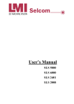
First Display Page
A125 Provide one first display page
automatically when PC and A125 is power on
and keep until PC start to display message on
LCD or Clear LCD.
SYSTEM BOOTING
>>>>>>>>>>>
This function support only firmware ver:1.3 and
after.
ICP Electronics Inc.
Other commands
The ICP Peripheral Communication Protocol in
Appendix A comprises 12 commands and can
be separated in 2 groups.
Group A: from system to A125
Get_ID (0x00)
Get_Switches_Status (0x06)
Get_Protocol_Version (0x07)
Display_Character_On_LCD (0x0C)
Clear_LCD (0x0D)
Reset (0xFF)
Group B: From System to A125
Report_ID (0x01)
Report_Switches_Status (0x05)
Report_Protocol_Version (0x08)
Ack (0xFA)
Nack (0xFB)
Reset_OK (0xAA)
For more details, please refer to examples in
Appendix A
Page 3/15
ICP Electronics Inc.
Page 4/15
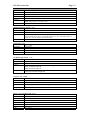
Appendix A
The ICP Peripheral Communication Protocol Version 0.3
History
2001/10/29
Version 0.3
Get ID : 0x00 and Report ID : 0x01
Direction
PC → A125
Command
Get ID
Code
0x4D 0x00
Explain
0x4D=Leading Code of PC; 0x00=Get ID Command
Example
0x4D 0x00
Response
A125 → PC
Command
Report ID
Code
0x53 0x01 0xXX 0xYY
Emphasis
0x53=Leading Code of A125; 0x01=Report ID; 0xXXYY=ID;
Example
0x53 0x01 0x00 0x7D (Board ID= 0x007D ---A125)
Report Button Status : 0x05 and Get Button Status : 0x06
Direction
A125 →PC
Command
Report Button Status (Auto Report when button is pressed or released or be polling by
Get Button Status Command)
Code
0x53 0x05 0xXX 0xYY
Explain
0x53=Leading Code of A125; 0x05=Report Button status Command;
0xXXYY=Buttons on/off, XXYY<15:0>=Button<15:0>, bit0= Button0, bit1=Button1,
1=Pressed, 0=Release.
Example
0x53 0x05 0x00 0x01 (Button0 is On)
0x53 0x05 0x00 0x00 (Button0 is Off)
Direction
PC → A125
Command
Get Button Status
Code
0x4D 0x06
Explain
0x4D=Leading Code of PC; 0x06=Get Button status Code;
Example
0x4D 0x06
Response
A125 →PC
Command
Report Button Status (Auto Report when button is pressed or released or be polling by
Get Button Status Command)
Code
0x53 0x05 0xXX 0xYY
Explain
0x53=Leading Code of A125; 0x05=Report Button status Command;
0xXXYY=Buttons on/off, XXYY<15:0>=Button<15:0>, bit0= Button0, bit1=Button1,
1=Pressed, 0=Release.
Example
0x53 0x05 0x00 0x01 (Button0 is On)
0x53 0x05 0x00 0x00 (Button0 is Off)
Get Protocol Version : 0x07 and Report Protocol Version : 0x08
Direction
PC → A125
Command
Get Protocol Version
Code
0x4D 0x07
ICP Electronics Inc.
Explain
Example
Response
Command
Code
Explain
Example
Page 5/15
0x4D=Leading Code of PC; 0x07=Get Protocol Version Command
0x4D 0x07
A125 → PC
Report Protocol Version
0x53 0x08 0xXX 0xYY
0x53=Leading Code of A125; 0x08=Report Protocol Version Command;
0xXX=Class; 0xYY=version (00~FF)
0x53 0x08 0x00 0x02 (Version 02)
Display Character on LCD : 0x0C
Direction
PC → A125
Command
Display Character on LCD
Code
0x4D 0x0C 0x0L 0x0N 0xCC1 ~ 0xCC15
Explain
0x4D=Leading Code of PC; 0x0C=Display Character On LCD Command; 0x0L=0x00
(Line 0), 0x0L=0x01 (Line 1); 0x0N=N Character (1~16), do not more than 16
characters; 0xCCn=ASCII Code of Characters,
Example
0x4D 0x0C 0x01 0x03 0x49 0x43 0x50 (Line 1, 3 Characters, ‘ICP’)
Clear LCD : 0x0D
Direction
PC → A125
Command
Clear LCD
Code
0x4D 0x0D
Explain
0x4D=Leading Code of PC; 0x0D=Clear LCD Command
Example
0x4D 0x0D
Set Back Light On/Off : 0x5E
Direction
PC → A125
Command
Set Back Light On/Off
Code
0x4D 0x5E 0xXX
Explain
0x4D=Leading Code of PC; 0x5E=Set Back Light On/Off Command,
0xXX=0x00 Back Light off,
0xXX=0x01 Back Light On
Example
0x4D 0x5E 0x01 ( Back Light On)
0x4D 0x5E 0x00 (Back Light Off)
Negative Ack : 0xFB
Direction
A125 → PC
Command
Negative Acknowledge the Command from PC, (means not support)
Code
0x53 0xFB 0xXX
Explain
0x53=Leading Code of A125; 0xFB=Negative Ack Command; 0xXX Command from
PC;
Example
0x53 0xFB 0xF0 (NAK 0xF0 Command)
Reset : 0xFF and Reset OK : 0xAA
Direction
PC → A125
Command
Reset
Code
0x4D 0xFF
Explain
0x4D=Leading Code of PC; 0xFF=Reset Command
Example
0x4D 0xFF
Response
A125 → PC
Command
Reset OK
Code
0x53 0xAA
ICP Electronics Inc.
Explain
Example
0x53=Leading Code of A125; 0xAA=Reset OK Command;
0x53 0xAA
Page 6/15
ICP Electronics Inc.
Page 7/15
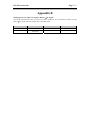
Appendix B
Modifying A125 to UART (+5V Signal) or RS232 (±12V Signal)
The internal signal from the micro processor of A125 is UART 5V. To switch between UART +5V and
RS232 ±12V signal interfaces, please refer to the table below.
Components
UART
RS232
U2
N/A
RS232 Transceiver like
LT1381CS
C1, 2, 3, 4, 5
N/A
0. 1uF
R3, 4
0 ohm
N/A
ICP Electronics Inc.
Page 8/15
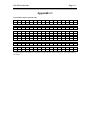
Appendix C
LCD-Module-supported ASCII codes
!
“
#
$
%
&
‘
(
)
*
+
,
.
/
0x20 0x21 0x22 0x23 0x24 0x25 0x26 0x27 0x28 0x29 0x2A 0x2B 0x2C 0x2D 0x2E 0x2F
0
1
2
3
4
5
6
7
8
9
:
;
<
=
>
?
0x30 0x31 0x32 0x33 0x34 0x35 0x36 0x37 0x38 0x39 0x3A 0x3B 0x3C 0x3D 0x3E 0x3F
@
A
B
C
D
E
F
G
H
I
J
K
L
M
N
O
0x40 0x41 0x42 0x43 0x44 0x45 0x46 0x47 0x48 0x49 0x4A 0x4B 0x4C 0x4D 0x4E 0x4F
P
Q
R
S
T
U
V
W
X
Y
Z
[
¥
]
^
_
0x50 0x51 0x52 0x53 0x54 0x55 0x56 0x57 0x58 0x59 0x5A 0x5B 0x5C 0x5D 0x5E 0x5F
`
a
b
c
d
e
f
g
h
i
j
k
l
m
n
o
0x60 0x61 0x62 0x63 0x64 0x65 0x66 0x67 0x68 0x69 0x6A 0x6B 0x6C 0x6D 0x6E 0x6F
p
q
r
s
t
u
v
w
x
y
z
{
|
}
→
←
0x70 0x71 0x72 0x73 0x74 0x75 0x76 0x77 0x78 0x79 0x7A 0x7B 0x7C 0x7D 0x7E 0x7F
**ASCII codes over the 0x80 are reserved for special symbols, please contact your sales representatives
for details.
ICP Electronics Inc.
Page 9/15
Appendix D
/*
*
*
*
*
*
*
*
*
*
*
*/
Title
Editor
Compilier
OS
Execute
:
:
:
:
:
A125 Demo program
Davis Wang in ICP Electronic
TC 2.0
DOS 6.22 or Above
C:\A125 String0 String1
where String0 will display on LCD line 0
String1 will display on LCD line 1
e.g. C:\A125 ICP Electronic
#include <dos.h>
#include <stdio.h>
#include <conio.h>
#define COM1 0x3f8
#define COM2 0x2f8
#define IOBASE COM1
void InitUART(void){
outport(IOBASE+3,
outport(IOBASE+0,
outport(IOBASE+1,
outport(IOBASE+3,
0x80);
0x60);
0x00);
0x03);
/* Line Control Register */
/* Divisor Latch Low
*/
/* Divisor Latch High
*/
}
void SendByte(char ch){
while(!(inport(IOBASE+5) & 0x20));
outport(IOBASE, ch);
}
char GetByte(void){
while(!(inport(IOBASE+5) & 0x01));
return inport(IOBASE);
}
void Clear_LCD(void){
SendByte(0x4D);
SendByte(0x0D);
}
ICP Electronics Inc.
void SendString(int line, char *s){
int i,j;
i=strlen(s);
SendByte(0x4D);
SendByte(0x0C);
SendByte(line);
SendByte(i);
for(j=0; j<i; j++)SendByte(*(s+j));
}
void main(int argc, char *argv[]){
InitUART();
Clear_LCD();
switch(argc){
case 2:
SendString(0, argv[1]);
break;
case 3:
SendString(0, argv[1]);
SendString(1, argv[2]);
break;
}
}
Page 10/15
ICP Electronics Inc.
/*
*
*
*
*
*
*
*
*
*
*
*
*/
Page 11/15
Title
: A125.c Demo program
Editor
: Davis Wang in ICP Electronic
Compilier : TCC Ver2.01
Use "TCC A125.C" to Compile A125.c
OS
: DOS 6.22 or Above
Execute : USE "C:\A125"
e.g. C:\A125
Result
: press any button on A125, and to see button's status
reflect on PC monitor
#include <dos.h>
#include <stdio.h>
#include <conio.h>
#define COM1 0x3f8
#define COM2 0x2f8
#define IOBASE COM1
void InitUART(void){
outport(IOBASE+3,
outport(IOBASE+0,
outport(IOBASE+1,
outport(IOBASE+3,
0x80);
0x60);
0x00);
0x03);
/* Line Control Register */
/* Divisor Latch Low
*/
/* Divisor Latch High
*/
}
void SendByte(char ch){
while(!(inport(IOBASE+5) & 0x20));
outport(IOBASE, ch);
}
unsigned char Rs232Available(void){
return inport(IOBASE+5)&0x01;
}
char GetByte(void){
while(!(inport(IOBASE+5) & 0x01));
return inport(IOBASE);
}
void SendString(int line, char *s){
ICP Electronics Inc.
int i,j;
i=strlen(s);
SendByte(0x4D);
SendByte(0x0C);
SendByte(line);
SendByte(i);
for(j=0; j<i; j++)SendByte(*(s+j));
}
void Read_A125(void){
unsigned char Data1;
unsigned char Data2;
if(GetByte()!=0x53)return; /* A125 Leading Byte */
switch(GetByte()){
case 0x01: /* Report ID */
Data1=GetByte();
Data2=GetByte();
printf("Board ID is 0x%04X\n", (Data1<<8)|Data2);
break;
case 0x05: /* Report Key Status */
Data1=GetByte(); /* Data Byte 1 */
Data2=GetByte(); /* Data Byte 2 */
switch(Data2&0x03){
case 0x00:printf("Button is Released\n"); break;
case 0x01:printf("Button 0 is Pressed\n"); break;
case 0x02:printf("Button 1 is Pressed\n"); break;
}
break;
}
}
void GetID(void){
SendByte(0x4D);
SendByte(0x00);
}
void main(void){
InitUART();
GetID();
while(!kbhit()){
if(Rs232Available())Read_A125();
}
}
Page 12/15
ICP Electronics Inc.
/*
*
*
*
*
*
*
*
*
*
*
*
*/
Title
: A125.C Demo Program
Editor
: Davis Wang in ICP Electronic
Compilier : gcc
use "gcc -o A125 A125.c" to compile A125.c
OS
: Linux
Execute : USE "[..]$A125 String0 String1" as root
Where String0 will display on LCD line0
String1 will display on LCD line1
e.g. [root@localhost davis]$ ./A125 ICP Electronic
#include
#include
#include
#include
#include
<stdio.h>
<sys/ioctl.h>
<fcntl.h>
<termios.h>
<stdlib.h>
struct termios tio;
int fd;
void InitUART(void){
if((fd=open("/dev/ttyS0", O_RDWR|O_NDELAY|O_NOCTTY))<0){
printf("Could not open Serial Port\n");
exit(1);
}
tio.c_cflag
=B1200|CS8|CREAD|CLOCAL;
tio.c_cc[VTIME] =0;
tio.c_cc[VMIN]
=0;
tcflush(fd, TCIFLUSH);
tcsetattr(fd, TCSANOW, &tio);
fcntl(fd, F_SETFL, FNDELAY);
}
void Clear_LCD(void){
char s[]={0x4D, 0x0D};
write(fd, s, 2);
}
void SendString(int line, char *s){
unsigned char c[]={0x4D, 0x0C, 0x00, 0x00};
c[2]=line;
Page 13/15
ICP Electronics Inc.
c[3]=strlen(s);
write(fd, c, 4);
write(fd, s, strlen(s));
}
int main(int argc, char *argv[]){
InitUART();
Clear_LCD();
switch(argc){
case 2:
SendString(0, argv[1]);
break;
case 3:
SendString(0, argv[1]);
SendString(1, argv[2]);
break;
}
close(fd);
}
Page 14/15
ICP Electronics Inc.
Page 15/15
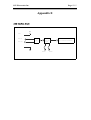
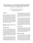
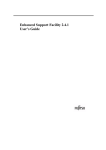
Appendix E
A125 Function Block
VCC
+5VDC
RS232 In
RS232 Out
BUF
8 bit MCU
(16C63)
BUTTON 0
BUTTON 1
16 x 2 Character LCD Module