1
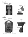
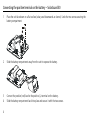
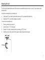
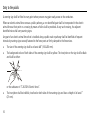
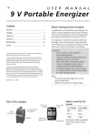
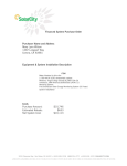
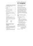
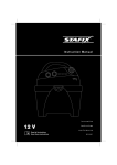
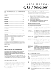
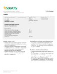
electric fence energizer user manual SolarGuard 50, SolarGuard 155 TM TM If you suspect the unit is not working then follow these steps: STOP! Do not return this product to the store 1. Disconnect the unit from the fence and check the indicator light is flashing. 2. Check the battery connection and voltage. 3. Check that the voltage between the live and ground terminals is greater than 7000 V using a fence voltage tester. 4. If these tests are OK you have an installation problem. Consult your user manual for installation and operating instructions or contact Tru-Test Group Customer service on 800-874-8494. w w w.p at r io t g lobal. com 2 Key to symbols on the unit Fence ground terminal (green). Connect the fence ground terminal to the ground system. Fence output terminal (red). Connect the fence output terminal to the fence. Risk of electric shock! This unit should be opened or repaired only by qualified personnel. No user serviceable parts. Before first use Before using the unit for the first time, you must: 1 2 Connect the battery (the positive terminal is disconnected before shipping). Charge the battery by placing the unit in full sunlight for three days with the solar panel facing true south in the northern hemisphere and true north in the southern hemisphere. Read full instructions before use. This unit must NOT be disposed of with other normal waste. Instead, it is your responsibility to dispose of it correctly by handing it over to a local authority responsible for collecting electrical and electronic equipment waste. 3 Connecting the positive terminal on the battery – SolarGuard 50 1 Place the unit face-down on a flat surface (solar panel downwards as shown). Undo the two screws securing the battery compartment. 2 Slide the battery compartment away from the unit to expose the battery. 3 4 Connect the positive (red) lead to the positive (+) terminal on the battery. Slide the battery compartment back into place and secure it with the two screws. 4 Connecting the positive terminal on the battery – SolarGuard 155 1 Place the unit upside-down on a flat surface (handle downwards as shown). Open the battery compartment by pressing both latches firmly and pushing upwards. 2 3 Connect the positive (red) lead to the positive (+) terminal on the battery. Close the battery compartment, ensuring the latches are securely fastened. 5 Installation Positioning the unit Install the unit: 6 adjacent to the electric fence preferably in the middle of the electric fence where it will receive the most daily sun throughout the season where a good ground can be obtained away from flooding and out of reach of animals and children (inside a protective fence, if required) with the solar panel facing true south in the northern hemisphere and true north in the southern hemisphere. Mounting the unit The unit may be placed directly onto a flat surface or mounted directly onto a steel Y-post or T-post using the postmounting slot. It can also be mounted onto a wooden post. SolarGuard 50 - you need 2 galvanized washers and 2 x galvanized flat head nails. SolarGuard 155 - mounting hardware is provided. To mount onto a wooden post: 1 2 3 4 Thread a washer onto each nail. Space the nails 3” (75 mm) apart. Hammer in the nails, allowing them to protrude by 3/8” (10 mm). Slide the unit onto the nails with the washers inside the post-mounting slot. 7 Connecting to an electric fence 1 2 Push a 3’ (1 m) ground rod fully into firm soil. Connect the green lead from the Fence ground terminal 3 Connect the red lead from the Fence output terminal on the unit to the fence. Make sure there is a good contact. on the unit to the grounding system. Caution! Make sure the connecting leads drop downwards from the unit to prevent water from collecting at the terminals. 8 Operation Switching on and off 1 To switch on, press and hold until the pulse indicator light gives one long flash (one second). 2 To switch off, press and hold until the pulse indicator light gives five short flashes. Pulse indicator light The pulse indicator light indicates the output pulse speed. The pulse speed varies according to the battery charge level: Battery charge level Normal Typical pulse speed A pulse every 1.5 seconds Low A pulse every 3 seconds Standby mode An intelligent battery management feature puts the unit into Standby mode when battery charge falls below a ‘safe operating level’. When in Standby mode, the unit is still on, but it will not deliver a pulse to the electric fence. The unit will resume delivering pulses when the solar panel has charged the battery so that it is above ‘safe operating level’. When operation resumes, the battery charge level will still be low, so the unit will deliver one pulse every 3 seconds. Once the battery reaches normal charge level, the pulse will revert to one pulse every 1.5 seconds. 9 Battery information Battery charging The solar panel can fully charge a flat battery in two weeks, provided the unit is switched off and there is adequate sunlight. A battery charger may also be used to charge the battery. Use a battery charger suitable for charging sealed, lead-acid batteries. Battery charger details Warning! The battery must be disconnected and removed from the unit before connecting it to a battery charger. Model SolarGuard 50 Battery type being charged 6V Battery charger requirements 6.9 V, 0.5 A SolarGuard 155 12 V 13.8 V, 1 A When fully charged, the battery should be able to power the unit for up to two weeks (SolarGuard 50) or up to three weeks (SolarGuard 155) with no sunlight. 10 Replacing the battery If a replacement battery is required, use a sealed lead-acid battery. Warning! Do not use a non-rechargeable battery. Replacement battery details Model SolarGuard 50 Suitable battery type 6 V, 3.5 Ah battery SolarGuard 155 12 V, 7 Ah battery Do not dispose of the battery in a land-fill or in a fire. In the event of a spill or leakage from a sealed lead-acid battery: Contain small spills with dry sand, soil and vermiculite. Do not use combustible materials. If possible, carefully neutralize spilled electrolyte with soda ash, sodium bicarbonate, lime, etc. Wear acid-resistant clothing, boots, gloves and a face shield. Do not let un-neutralised acid get into the sewage system. Neutralized acid must be managed in accordance with approved local, state and federal requirements. Consult your state environmental agency and/or federal EPA. 11 Maintenance Clean the solar panel regularly with a soft cloth using glass cleaner or a mild solution of detergent and water. This will ensure the solar panel functions efficiently. Caution! Do not immerse the unit in water. When transporting the unit, protect the solar panel to prevent the glass surface from being damaged. Storage If the unit is stored for extended periods, the battery can discharge and become damaged. The unit should be stored inside, next to a window, where sunlight can shine on the unit each day. If the unit cannot be stored in a sunny position, it should be kept in a cool place. The battery should be fully charged and disconnected from the unit. The battery should be recharged manually every six months using a suitable battery charger. Building an electric fence For information about building an electric fence, refer to the Patriot website www.patriotglobal.com. 12 Temporary electric fencing A temporary fence can be quickly erected and easily moved allowing the farmer to: Make smaller paddocks (fields) Keep herds of animals separated Ration feed Note: Use more wires for smaller animals and wild animals. Politape should be used when greater visibility is required (e.g. horses). An example of a temporary fence is shown below. 13 Safety considerations Warning! - Do not connect to mains-operated or line-operated equipment. Remove the battery from the unit before using an external battery charger to recharge the battery. Switch the unit off before installation or performing any work on the fence. Read all the safety considerations carefully. Check your installation to ensure that it complies with all local safety regulations. Do not connect simultaneously to a fence and to any other device such as a cattle trainer or a poultry trainer. Otherwise, lightning striking your fence will be conducted to all other devices. Notes: - This product has been designed for use with electric animal fences. Keep these instructions in a handy location. Safe electric fence construction Warning! Read before use. An electric fence can be hazardous when there is a risk of entrapment or entanglement, or other hazards exist. Serious injury or death may result. Take all steps to avoid the risk of entrapment or entanglement. 14 Hazards Do not climb through or under an electric fence. If it is necessary to cross an electric fence use a gate or specially designed crossing point. Do not allow young or infirm persons to use this unit without supervision. Do not allow young children to play with this unit or near an electric fence or electrified wires. Do not electrify barbed wire. Do not support off-set electrified wires less than 6" (150 mm) from a barbed wire fence. Do not electrify any fence construction which could lead to entanglement of persons or animals. We recommend for instance, that no more than one electrified off-set wire be supported on either side of a barbed wire or mesh fence. Do not supply an electric fence from two units. Do not allow electrified wires from two units on the same or adjacent properties to be less than 8' (2.5 m) apart. Do not place the unit's ground rod within 33' (10 m) of any part of a power supply ground system or telecommunications ground system. Do not run electric fence wires above or close to overhead power or communication lines. 15 Duty to the public A warning sign shall be fitted to every point where persons may gain ready access to the conductors. Where an electric animal fence crosses a public pathway, a non-electrified gate shall be incorporated in the electric animal fence at that point or a crossing by means of stiles shall be provided. At any such crossing, the adjacent electrified wires shall carry warning signs. Any part of an electric animal fence that is installed along a public road or pathway shall be identified at frequent intervals by warning signs securely fastened to the fence posts or firmly clamped to the fence wires. The size of the warning sign shall be at least 4x8" (100x200 mm). The background colour of both sides of the warning sign shall be yellow. The inscription on the sign shall be black and shall be either: or the substance of "CAUTION: Electric fence". The inscription shall be indelible, inscribed on both sides of the warning sign and have a height of at least 1" (25 mm). 16 Definition of special terms Unit/Charger/Energizer – An appliance that is intended to periodically deliver voltage impulses to a fence connected to it. Fence – A barrier for animals or for the purpose of security, comprising one or more conductors such as metal wires, rods or rails. Electric fence – A barrier which includes one or more electric conductors, insulated from ground, to which electric pulses are applied by a unit. Ground rod – Metal structure that is driven into the soil near a unit and connected electrically to the Fence ground terminal of the unit, and that is independent of other grounding arrangements. Connecting lead – An electric conductor, used to connect the unit to the electric fence or the ground rod. Requirements for electric animal fences Electric animal fences and their ancillary equipment shall be installed, operated and maintained in a manner that minimises danger to persons, animals or their surroundings. This unit is not intended for use by persons (including children) with reduced physical, sensory or mental capabilities, or lack of experience and knowledge, unless they have been given supervision or instruction concerning use of the unit by a person responsible for their safety. Children should be supervised to ensure that they do not play with the unit. 17 Electric animal fence constructions that are likely to lead to the entanglement of animals or persons shall be avoided. An electric animal fence shall not be supplied from two separate units or from independent fence circuits of the same unit. For any two separate electric animal fences, each supplied from a separate unit independently timed, the distance between the wires of the two electric animal fences shall be at least 8' (2.5 m). If this gap is to be closed, this shall be effected by means of electrically non-conductive material or an isolated metal barrier. Barbed wire or razor wire shall not be electrified by a unit. A non-electrified fence incorporating barbed wire or razor wire may be used to support one or more offset electrified wires of an electric animal fence. The supporting devices for the electrified wires shall be constructed so as to ensure that these wires are positioned at a minimum distance of 6" (150 mm) from the vertical plane of the non-electrified wires. The barbed wire and razor wire shall be grounded at regular intervals. Go to www.patriotglobal.com for information about grounding. A distance of at least 33' (10 m) shall be maintained between the unit's ground rod and any other grounding system connected parts such as the grounding system for the power supply or the telecommunication system. Connecting leads that are run inside buildings shall be effectively insulated from the grounded structural parts of the building. This may be achieved by using insulated high voltage cable. Connecting leads that are run underground shall be run in conduit of insulating material or else insulated high voltage cable shall be used. Care must be taken to avoid damage to the connecting leads due to the effects of animal hooves or vehicle wheels sinking into the ground. 18 Connecting leads shall not be installed in the same conduit as the AC supply wiring, communication cables or data cables. Connecting leads and electric animal fence wires shall not cross above overhead power or communication lines. Crossings with overhead power lines shall be avoided wherever possible. If such a crossing cannot be avoided it shall be made underneath the power line and as nearly as possible at right angles to it. If connecting leads and electric animal fence wires are installed near an overhead power line, the clearances shall not be less than those shown in the table below. Minimum clearances from power lines for electric animal fences Power line voltage Clearance 1000 V 10 ' (3 m) 1000 V to 33,000 V 13' (4 m) 33,000 V 27' (8 m) If connecting leads and electric animal fence wires are installed near an overhead power line, their height above the ground shall not exceed 10' (3 m). This height applies to either side of the orthogonal projection of the outermost conductors of the power line on the ground surface, for a distance of: 6'6" (2 m) for power lines operating at a nominal voltage not exceeding 1000 V. 50' (15 m) for power lines operating at a nominal voltage exceeding 1000 V. Electric animal fences intended for deterring birds, household pet containment or training animals such as cows need only be supplied from low output units to obtain satisfactory and safe performance. 19 In electric animal fences intended for deterring birds from roosting on buildings, no electric fence wire shall be connected to the unit's ground rod. Ensure that all line-operated, ancillary equipment connected to the electric animal fence circuit provides a degree of isolation between the fence circuit and the supply mains equivalent to that provided by the unit. Protection from the weather shall be provided for the ancillary equipment unless this equipment is certified by the manufacturer as being suitable for use outdoors, and is of a type with a minimum degree of protection IPX4. Troubleshooting Problem Action The pulse indicator light is flashing, but the electric shock delivered by the fence is weak. Check that all connections in the fence and ground system are firm and secure. If necessary, clean away any corrosion. Check that the ground rod is pushed firmly into firm ground. Check for faults in the fence-line caused by trees or vegetation. If necessary, remove obstructions and mend the fence. Check that the unit (charger) rating is adequate for the length of the fence. If necessary, reduce the length of the fence or reduce the number of fence wires. Alternatively, divide the fence-line into smaller zones, with each zone powered by a separate unit. 20 The pulse indicator light is not flashing. Check that the unit is switched on. If there has been insufficient sunlight to charge the battery, the unit may be in Standby mode. Charge the battery by placing the unit in full sunlight with the solar panel facing true south in the northern hemisphere and true north in the southern hemisphere. Ensure the battery is connected correctly with the positive (red) lead to the positive (+) terminal on the battery and the negative (black) lead to the negative (–) terminal on the battery. Try charging the battery manually using a suitable battery charger.See Battery charging on page 10. Replace the battery with a new battery. Before installing a new battery, charge it fully using a suitable battery charger. If the pulse indicator light is still not flashing, return the unit to a service agent appointed by Tru-Test Group for repair. The battery needs frequent replacement. Check that the solar panel is clean and is not damaged. See Maintenance on page 12. Make sure the unit is positioned to receive maximum sunlight. If necessary, remove any objects or vegetation that might be casting a shadow on the unit. See Positioning the unit on page 6, or for more detailed information on solar installations, refer to the Tru-Test Group website www.tru-test.com. 21 After the unit is switched on, the pulse indicator light gives three long flashes (2 seconds) then the unit appears to be off. The unit is in Standby mode because there has been insufficient sunlight to charge the battery. Charge the battery by placing the unit in full sunlight with the solar panel facing true south in the northern hemisphere and true north in the southern hemisphere. The pulse indicator light flashes quickly several times and then there is a pause. There may be a problem with the unit. Return the unit to a service agent appointed by Tru-Test Group for repair. Servicing SolarGuard 50 - This unit cannot be serviced. Please refer to the warranty conditions at www.patriotglobal.com. SolarGuard 155 - This unit contains no user serviceable parts. It must be returned to a service agent appointed by TruTest Group for repair. Note: If you suspect the unit is not working, always check the battery connection and voltage before proceeding. 22 Warranty This warranty does not cover defects caused by: Incorrect input voltage or polarity Damage to external wiring Physical mishandling Water immersion Vermin or insect damage This warranty covers defects caused by lightning. Note: This product has been manufactured to comply with international safety standards. This product is warranted against faulty material and workmanship for a period of 2 years FROM DATE OF PURCHASE. If a warranted defect occurs, return this product with proof of purchase to an authorised service centre. For details, see www.patriotglobal.com. Note: - No responsibility is accepted for any accident or damage caused subsequent to any tampering with or modification to or misuse of this product, including (but not limited to) alterations made by anyone other than Tru-Test Group or its agents. To the maximum extent permitted by law, this warranty is exclusive, personal to you and in lieu of all other warranties, representations or conditions relating to this product (whether express or implied and whenever arising) whether originating by statute, law, trade, custom or otherwise. 23 Consulte nuestra página web patriotglobal.com para acceder a las instrucciones completas de instalación y funcionamiento. Pour les instructions complètes d’installation et d’utilisation, veuillez vous reporter à notre site web patriotglobal.com. Explication des symboles sur l’électrificateur Borne de terre de la clôture (vert). Connectez la borne de terre au système de mise à la terre de l’électrificateur. Borne de sortie vers la clôture (rouge). Connectez la borne de sortie à la clôture. Risque de choc électrique ! L’électrificateur ne doit être ouvert ou réparé que par un personnel qualifié. Pas de pièces réparables par l’utilisateur. Lire attentivement toutes les instructions avant usage. Cet appareil ne doit PAS être jeté avec les ordures ménagères ordinaires. Il est de votre responsabilité de l’éliminer correctement en l’apportant à une autorité locale responsable de la collecte de déchets d’équipements électriques et électroniques. 24 Attention ! - Déconnectez la batterie de l’électrificateur avant de la brancher à un chargeur. - Ne pas utiliser une batterie non rechargeable. Warning! - Ne jamais raccorder cet appareil à des équipements alimentés par le réseau électrique. - La batterie doit être déconnectée et retirée de l'électrificateur avant sa connexion à un chargeur. - Éteignez l’électrificateur avant tout travail d’installation ou toute autre intervention sur la clôture. - Lisez attentivement toutes les règles de sécurité. - Vérifiez soigneusement que votre clôture est en conformité avec tous les règlements locaux de sécurité. - Ne raccordez jamais un électrificateur simultanément à une clôture et à un autre appareil tel qu’un système de dressage de bétail ou de volaille. Sinon, la foudre pouvant tomber sur votre clôture risque de s’étendre à tous les autres appareils. Notes : - Ce produit a été conçu pour une utilisation avec des clôtures électriques pour animaux. Gardez ces instructions à un endroit pratique. Installation d’une clôture électrique sûre Attention ! Lisez avant utilisation. Une clôture électrique peut être dangereuse si elle présente un risque d’embrouillement ou d’emmêlement ou que d’autres risques existent. Des blessures graves ou la mort peuvent en être la conséquence. Prenez les mesures nécessaires pour éviter tout risque d’embrouillement ou d’emmêlement. 25 Dangers Ne passez pas par-dessus ou par-dessous une clôture électrique. Si vous devez traverser une clôture électrique, utilisez une porte ou un passage spécialement aménagé. Ne permettez jamais aux enfants ou à des personnes ayant une quelconque infirmité d’utiliser cet appareil sans supervision. Ne laissez jamais jouer un enfant avec cet appareil ou à proximité d’une clôture électrique ou d’un fil électrifié. N’électrifiez jamais des fils barbelés. N’installez jamais des fils électrifiés décalés à moins de 6” (150 mm) d’un fil barbelé. N’électrifiez jamais une clôture qui pourrait entraîner un risque d’emmêlement pour l’homme ou les animaux. Nous vous recommandons, par exemple, de n’installer qu’un seul fil décalé électrifié par côté d’un fil barbelé ou d’un grillage. N’alimentez jamais une clôture électrique par deux électrificateurs. Assurez toujours une distance d’au moins 8’ (2,5 m) entre des fils électrifiés de deux appareils sur le même lotissement ou un lotissement voisin. Ne mettez jamais la prise de terre de l’électrificateur à moins de 33’ (10 m) de toute partie d’une prise de terre d’un réseau électrique ou de lignes de télécommunication. N’installez jamais des fils de clôture électrique au-dessus ou près de lignes électriques ou de télécommunication aériennes. Définitions des termes techniques Électrificateur de clôture : appareil émettant régulièrement des impulsions électriques à la clôture connectée à l’électrificateur. Clôture : une barrière utilisée pour contenir des animaux ou pour des raisons de sécurité qui comprend une ou plusieurs conducteurs tels fils métalliques, piquets ou lattes. Clôture électrique : une barrière comprenant un ou plusieurs conducteurs électriques, isolée de la terre et soumise à des impulsions électriques générées par un électrificateur. Prise de terre : structure métallique enfoncée dans le sol à proximité d’un électrificateur et connectée électriquement à la borne de terre de l’électrificateur, structure séparée de tout autre système de mise à la terre. 26 Obligation envers le public Une plaque de signalisation doit être mise en place partout où des personnes auront accès aux conducteurs. Partout où une clôture électrique pour animaux croise un chemin public, une porte non électrifiée sera incorporée à la clôture électrique pour animaux ou bien un passage au moyen d’une échelle sera prévu. Les fils électrifiés adjacents à ces passages doivent être munis de plaques de signalisation. Toute partie d’une clôture électrique pour animaux installée le long d’une voie publique ou d’un sentier sera signalée à des intervalles fréquents par des plaques de signalisation qui seront solidement attachées aux piquets ou accrochées à la ligne de clôture. La taille des plaques de signalisation sera au moins de 4x8” (100x200 mm). La couleur de fond des plaques doit être jaune des deux côtés. L’inscription sur la plaque doit être en noir et soit indiquer le symbole ci-dessous : soit indiquer en substance « ATTENTION : Clôture électrique ». L’inscription doit être ineffaçable, inscrite sur les deux côtes de la plaque de signalisation et avoir une hauteur minimale de 1” (25 mm). 27 Product specifications SolarGuard 50 SolarGuard 155 Power source 6 V, 3.5 Ah sealed lead-acid battery 12 V, 7 Ah, sealed lead-acid battery Typical current consumption <20 mA <20 mA Maximum output Voltage Energy up to 8.5 kV up to 0.05 J at 2000 up to 10 kV up to 0.15 J at 2000 Typical output at 1000 Voltage Energy up to 3.4 kV up to 0.05 J up to 3.8 kV up to 0.14 J Stored energy 0.07 J 0.21 J Unless otherwise stated, values are typical and normal production tolerances of ±10% should be allowed for. 819848 Issue 1 12/2011 © Tru-Test Limited. All rights reserved. 28