1
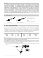
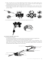
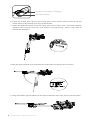
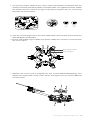
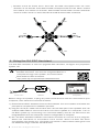
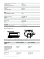
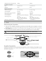
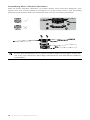
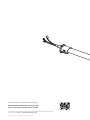
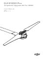
DJI E1200 Pro
Propulsion Upgrade Kit For S900
User Manual
V1.0
2015.03
Disclaimer
Thank you for purchasing the E1200 Pro Propulsion Upgrade Kit for S900 (hereinafter
referred to as “product”). Read this disclaimer carefully before using this product. By
using this product, you hereby agree to this disclaimer and signify that you have read
it fully. Please install and use this product in strict accordance with the manual. DJI
assumes no liability for damage(s) or injuries incurred directly or indirectly from using,
installing or refitting this product improperly, including but not limited to using accessories
not designated.
This device complies with part 15 of the FCC Rules.
DJI is the registered trademark of SZ DJI Technology Co., Ltd. (abbreviated as “DJI”).
Names of product, brand, etc., appearing in this manual are trademarks or registered
trademarks of their respective owner companies. This product and manual are
copyrighted by DJI with all rights reserved. No part of this product or manual shall be
reproduced in any form without the prior written consent or authorization of DJI.
This disclaimer is made in various language versions; in the event of divergence
among different versions, English version shall prevail.
Warnings
When powered on, the motors and propellers will rotate very quickly and may cause
serious damage or injury. Always be vigilant and make safety your top priority.
1. Always fly your aircraft at a safe distance from people, animals, power lines, and
other obstacles.
2. Do not get close to or touch the motors or propellers when the unit is powered on.
3. Before flying, ensure that the propellers and frame arms are installed correctly and
that the propellers are unfolded.
4. Ensure that all ESC connectors and power cables connectors are securely
attached before every flight.
5. Ensure that all dampers are in good condition before every flight. If they are not,
they may adversely affect flight performance and should be replaced prior to
flight.
6. Check to ensure that all parts of the aircraft are in good condition before flight. Do
not fly with worn or damaged parts.
7. Only use compatible DJI parts.
Legend
Important
Hints and Tips
If you encounter any problems or if you have any questions, please contact your local
DJI authorized dealer or DJI Support.
DJI Support Website:
www.dji.com/support
© 2015 DJI. All Rights Reserved. 1
About
The E1200 Pro Propulsion Upgrade Kit for S900 is designed for use with DJI S900
multirotor flying platforms. The E1200 Pro features enhanced efficiency, security, and
endurance. The Z-Blade 17-inch foldable propellers are made using an advanced
carbon-fiber-reinforced polymer, which reduces rotational inertia and enhances
rigidity. New, upgraded motors promote efficient heat dissipation to improve
endurance and reliability, even when flying in harsh environments. The Smart ESCs
feature a sinusoidal drive, which provides greater efficiency and more agile dynamic
response. After upgrading with this kit, your S900 will feature enhanced flight
endurance, increased maximum takeoff weight, higher maximum takeoff altitude, and
an extended range of environmental working temperatures.
1. In the Box
Screw Package:
Screws for arms (M3×14 hexagon)
Screws for foldable propellers
(M3×12.5 hexagon)
Screws for propeller mount cover
(M3×8)
Frame Arm
Clockwise ×1
Frame Arm
Counter-Clockwise ×1
Screws for motor base mount
(M3×12 hexagon)
Soft dampers, Propeller washers
2. Gain Value Settings
The new E1200 Pro ESC, features a sinusoidal drive, which replaces the traditional
square wave drive to offer improved performance when accelerating and
decelerating. To achieve the same sensitivity as older ESCs, which use a traditional
square wave drive, reduce the gain values according to your flight control system
and frame. The table below shows typical gain values when using the E1200 Pro and
a DJI A2 flight control system on a platform with a takeoff weight of 8 kg:
Basic
Attitude
Pitch
Roll
Yaw
Pitch
Roll
Vertical
110%
110%
55%
160%
160%
85%
3. Installation
Tools compatible with the following screws are required:
Screws (M4×35), Screws for upper plate (M2.5×8 cheese head), Screws for round cover
(M3×8 self-tapping), Screws for power cable bracket (M3×5.5 square drive, hexagon)
1) Remove the original frame arms of the S900
a. If the frame arm is erect, twist the red knob at the arm junction and lower the frame
arm.
2 © 2015 DJI. All Rights Reserved.
b. Now unscrew the six screws (M2.5×8 cheese head) on the upper plate of the
center frame and remove the upper plate. Then unscrew the four screws (M3×8
self-tapping) that secure the round cover and remove it.
c. Disconnect each ESC signal cable from the center frame. Then remove each
screw (M3×5.5 square drive, hexagon) on the connecting bracket and unplug the
power cables.
d. Unscrew the M4×35 screw and remove the original frame arm.
2) Install the upgrade frame arms
a. Prepare the arms by:
Checking all propellers for cracks and ensuring that all screws are tightened,
Ensuring that all motors are mounted firmly and rotate freely,
Identifying the clockwise and counter-clockwise marks on the propellers. The
arms with the counter-clockwise marks will be mounted at positions M1, M3 and
M5 of the center frame. The arms with the clockwise marks will be mounted at
positions M2, M4 and M6 of the center frame.
ESC Signal Cable
JST 3-pin Cable
Power Cables
Screw Mount
CW or CCW Mark
Propeller
Motor
Built-in ESC
© 2015 DJI. All Rights Reserved. 3
Screws for Arms (M3×14 hexagon)
ESC LED Indicator
b. Insert the frame arm into the mounting slot on the center frame and line up the
screw holes of the frame arm and center frame.
c. Insert the M4×35 screw from the right side of the frame arm, as shown below.
Tighten each screw securely, but avoid over-tightening, which may lead to
connector abrasion.
d. Gently lift the frame arm and twist the red knob to lock the arm in place.
e. Plug each ESC signal cable into the slot nearest to each arm on the center frame.
4 © 2015 DJI. All Rights Reserved.
f. Connect the power cables to the center frame. Red cables correspond with the
positive terminals and black cables correspond with the negative terminals. Rotate
the bracket screws until they are tight and properly aligned with the connecting
brackets, as shown below.
g. Tuck the excess length of the JST 3-pin cable back into the frame arm to avoid any
potential flight complications.
h. Ensure that all ESC signal cables and power cables are correctly connected onto
the center frame.
ESC Signal Cables
Power Cables
i. Replace the round cover and tighten the four screws (M3×8 self-tapping), then
replace the upper plate of the center frame and tighten the six screws (M2.5×8
cheese head).
© 2015 DJI. All Rights Reserved. 5
j. Double check all frame arms. Arms M1 and M2 correspond with the nose
direction of the aircraft. Arms M4 and M5 correspond with the tail. When viewed
from above, the motors on arms M1, M3 and M5 should rotate counter clockwise
and the motors those on arms M2, M4 and M6 should rotate clockwise.
M2
M1
M3
M6
M4
M5
4. Using the DJI ESC Assistant
The DJI ESC Assistant is used to upgrade ESC firmware, configure the propulsion
system, etc.
An Updater is required and is not included with the E1200 Pro. To use the
DJI ESC Assistant, connect the integrated ESC to a
computer through the Updater, as shown below.
Download the ESC Assistant:
http://www.dji.com/product/e1200/download
Frame Arm
Updater
Computer
Before using the Updater, unplug any other serial devices that are connected to your
computer, then follow the instructions below:
1) Download the ESC Assistant from the DJI website. Run the installer and follow the
prompts to complete the installation process.
2) Plug the JST 3-pin cable of the frame arm into the data port of the Updater and use
a Micro-USB cable to connect the other end of the Updater to a computer. Turn on
the ESC system by connecting it to a 6S LiPo battery and do not disconnect the
integrated ESC from the computer until the configuration is complete.
3) Run the ESC Assistant software and wait for the ESC to connect to the program.
Watch the indicators on the bottom of the screen. When the ESC has been
successfully connected, the “Computer Connection” status will be solid green and
the Data Exchange Indicator will blink blue.
6 © 2015 DJI. All Rights Reserved.
4) Click on the “View” tab. In the “ESC” section, check the current firmware version
and ensure that the installed firmware up-to-date. If it is not, click the link and
follow the prompts to update it.
If the ESC is not automatically recognized by the DJI ESC Assistant (the
indicators on the bottom of the screen show a solid green and an inactive
blue), check whether there is more than one DJI Updater, FTDI USB adapter,
or other developer tool (including, but not limited to, BeagleBone, Raspberry,
Arduino, etc.), which may use the FTDI chipset, connected to the computer. If
any of these FTDI devices are connected, simply unplug them and keep the
DJI Updater connected to the computer. Then, restart the DJI ESC Assistant
and the ESC system to form a successful connection.
5. ESC LED Indicator & Sound Description
LED Indicators
Sound
Description
Yellow-Green, blinking in
turn
None
Motor is being connected
/
Red or Green, blinking
slowly
—/
—
Solid Red or Green
1356
Ready
None
Motor starts normally
None
Self-test failure
BB---BB---BB… Input voltage is abnormal
Red-Yellow, blinking in turn
Yellow, blinking quickly
Yellow, blinking slowly
— Solid Yellow
Red, blinking quickly
BBB----BBB…
The motor parameters don’t
match the firmware data saved in
the ESC
BBBBBB…
Throttle stick is not at the bottom
position
B------B------B… No signal input
None
Motors are rotating at full throttle
None
Error, land your aircraft
immediately*
* You can learn more about an error by connecting the integrated ESC to the ESC
Assistant.
You can interpret the working status of the unit by observing the LEDs and
listening to the sounds emitted from the ESC.
6. Specifications
Max Thrust
3900 g/rotor @ 25 V (Sea Level)
Takeoff Weight Recommended
1200 to 1400 g/rotor (Sea Level)
Battery Recommended
6S LiPo
© 2015 DJI. All Rights Reserved. 7
Frame Arm Weight (Single)
385 g
Cable Length
460 mm
Working Temperature
-10 to 60°C
Arm Tube
Length
290 mm
Outer Diameter
25 mm
Wall Thickness
1 mm
ESC
Max Allowable Voltage
26 V
Max Allowable Current (Persistent)
40 A
Signal Frequency
30 to 450 Hz
Battery
6S LiPo
Motor
Stator Size
42×16 mm
KV
310 rpm/V
Weight
205 g
Propeller
Diameter / Thread Pitch
17×6.0 inch
Motor Dimensions
4×M3 Thread depth 6 mm
12 mm
35 mm
52 mm
62 mm
18 mm
7. Comparison of the S900 Specifications
Specifications
Before Upgrading
After Upgrading
Frame
Diagonal Wheelbase
900 mm
920 mm
Frame Arm Length
358 mm
368 mm
Frame Arm Weight
(with Motor, ESC,
Propeller )
316 g
385 g
41×14 mm
42×16 mm
Motor
Stator Size
KV
400 rpm/V
310 rpm/V
Max Power
500 W
700 W
8 © 2015 DJI. All Rights Reserved.
Weight (with Cooling Fan)
158 g
205 g
Size
15×5.2 inch
17×6.0 inch
Weight
13 g
23 g
4.7 to 8.2 kg
4.7 to 10 kg
Foldable Propeller
Flight Parameters
Takeoff Weight
Total Weight
3.3 kg
3.7 kg
Max Power Consumption
3000 W
4000 W
Hovering Power
Consumption
1000 W
(@ 6.8 kg Takeoff Weight)
770 W
(@ 6.8 kg Takeoff Weight)
Hovering Time
18 min
(@ 12000 mAh with a
6.8 kg Takeoff Weight)
23 min
(@ 12000 mAh with a
6.8 kg Takeoff Weight)
Working Temperature
- 10 to 40 °C
- 10 to 60 °C
8. FAQ
Remounting the Propellers
1) Use the two foldable propeller mounting screws (M3×12.5 hexagon), the two
propeller cover mounting screws (M3×8), and the four propeller washers to remount
the propellers.
2) First apply thread locker to the thread of the propeller mount, then tighten the
screws until the propeller blades are securely clamped and can rotate freely.
Loose screws cannot be securely locked in place with thread locker.
Screws for Propeller Cover
(M3×8)
Screws for Foldable Propellers
(M3×12.5 hexagon)
Propeller Washers
Propeller Precautions
Check the markers on the screws and propeller covers before every flight. If the
propellers are loose, the markers will provide a visual cue, indicating that the screws
should be tightened.
© 2015 DJI. All Rights Reserved. 9
Assembling Motor Vibration Absorbers
Affix the motor vibration dampers, as shown below. First insert the dampers, then
tighten the four screws (M3×12 hexagon) on motor base mount. The assembly
process is identical for both the clockwise and counter-clockwise propellers.
Ensure that all dampers are in good condition before every flight. If they are
not, they may adversely affect flight performance and should be replaced
immediately.
10 © 2015 DJI. All Rights Reserved.
The content is subject to change.
Download the latest version from
http://www.dji.com/product/e1200
If you have any questions about this document, please contact DJI by
sending a message to [email protected].
© 2015 DJI. All Rights Reserved.