1
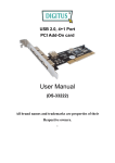
UHI/UHO Series Camera Housing
Quick Installation Guide
1. Opening the cover
2. Camera/Lens installation
3. Feed-through Wiring
Open the cover by unlatching the three
Remove the two screws holding the
Remove the two dome plugs located
latches on the side of the housing.
camera tray to the housing. Remove tray
inside the housing. Screw the two 3/8-
If the optional tamper-resistant screws
from the housing. Attach the lens to the
inch NPT fittings into the foot. Pull the
have been installed, use the supplied
camera. Use the various 1/4-20 screws
cabling through the fittings into the
wrench to remove the screws before
and spacers provided to mount the
housing. Tighten the fitting and attach the
opening the latches.
camera and the lens to the camera tray.
foot to the top bracket of the mount.
Ensure that the holes in the rear cap are
covered with the rubber plugs provided.
4. Power Connections
The terminal block accepts wire ranging from 0.5 mm² to 2.5 mm² (20 AWG to 14 AWG).
- To attach the external safety ground wire, remove the nut, the washers, and the external ground
wire lug from the ground post.
- Strip and crimp the external ground wire into the lug.
- Reattach the ground connections in the order shown in the side figure.
- Tighten the fitting to 8.5 N m to 9.0 N m (75 in. lb to 80 in. lb).
5. Wiring (All Models except UHO-HBPS-10, UHO-HBPS-50, and UHO-HPS-50)
Connect the supply power wires to the terminal block. Strip no less than 6 mm (0.25 in.) and no more than 8 mm (0.31 in.) of
insulation away from the wire. Ensure not to nick the wires. Cut the power cord on 120 VAC and 230 VAC camera models;
leave enough cable to allow connection to the terminal block. Strip no less than 6 mm (0.25 in.) and no more than 8 mm (0.31 in.)
of insulation away from the wire. Connect these wires to the connectors provided on the terminal block.
6. Video coax connection
7.Lens wiring
Install a 1/2-in. NPT fitting into the
Install the 3/8-in. NPT fitting into the
available hole in the rear cap.
middle hole in the rear cap. If installing a
Route the video coax cable through one
zoom lens, insert the lens control cable
of the fittings installed, or one of the
through the last fitting at the rear of the
feed-through fittings in the base. Attach
housing. Attach the lens wiring to the lens
the BNC connector to the coax and
mating connector and connect it to the
connect it to the camera.
lens. If a mating connector is not
Tighten the fitting to 8.5 N m to 9.0 N m
available, connect directly to the lens
(75 in. lb to 80 in. lb).
cable. Tighten the fitting. (See step 6.)
UHI/UHO Series
Camera Housing
Quick Installation Guide
8. Wiring (UHO-HBPS-10,-50, UHO-HPS-50)
Cut the power cord on 230 VAC camera
models, leaving enough cable for connection
to the terminal block. Strip no less than 6
mm (0.25 in.) and no more than 8 mm (0.31
in.) of insulation away from the wire. Be sure
not to nick the wires. Insert the power cord
through the back shell assembly and strain
relief. Connect the power cable to the screw
terminals on the provided mating connector.
9. Final assembly
10. Sunshield installation
11. Fuse replacement
1. Use the hole plugs provided to plug
1. Loosen the two screws (M4 x 10) on
1. To replace a fuse, pull the top of the
any unused holes in the rear cap.
the top of the housing.
fuse holder.
2. Replace the camera and bracket
2. Slide the sunshield to the desired
2. Replace the fuse with a fuse that has
back into the housing.
position. It has a range of 50 mm (2 in.).
the same current rating.
3. Slide the camera/lens tray into the
3. Tighten the screws to lock the
The fuse is a 5.2 mm x 20 mm slow
slot near the clasp side of the housing.
sunshield into position.
blow breaking capacity cartridge-type
4. Install screws.
4. If the sunshield is removed or not
fuse.
5. Close the cover and secure the
installed, plug the two screw holes with
latches.
the hole plugs supplied with the housing
6. Optional tamper-resistant screws
hardware kit.
are provided with the housing. Secure
the latch using these three screws and
There is a spare fuse inside the housing.
the provided tamper-resistant wrench.
Download the English version of the User Manual here:
http://us.boschsecurity.com/us_product/02_products_3/st_bu_f_277305_tams_catalog_prod_us/st_section_f_277848_ta
ms_catalog_prod_us/st_prodfam_p_277848_tams_catalog_prod_us_278254
OR from the page of UHO Series Outdoor Camera Housing on your country’s site linked from boschsecurity.com.
Bosch Security Systems B.V.
Torenallee 49 5617 BA Eindhoven
The Netherlands
www.boschsecurity.com
© Bosch Security Systems B.V., 2014