1
Pololu Dual MC33926 Motor Driver Shield User’s Guide
© 2001–2014 Pololu Corporation
Pololu Dual MC33926 Motor Driver
Shield User’s Guide
1. Overview . . . . . . . . . . . . . . . . . . . . . . . . . . . . . .
1.a. Features . . . . . . . . . . . . . . . . . . . . . . . . . . .
1.b. Included Hardware . . . . . . . . . . . . . . . . . . . . .
2. Contacting Pololu . . . . . . . . . . . . . . . . . . . . . . . . . .
3. Getting Started with an Arduino . . . . . . . . . . . . . . . . . .
3.a. What You Will Need . . . . . . . . . . . . . . . . . . . .
3.b. Assembly for Use as an Arduino Shield . . . . . . . . . .
3.c. Shield Connections: Signals, Power, and Motors . . . . . .
3.d. Programming Your Arduino . . . . . . . . . . . . . . . .
4. Using as a General-Purpose Motor Driver . . . . . . . . . . . . .
4.a. Assembly for Use as a General-Purpose Motor Driver . . .
4.b. Board Connections . . . . . . . . . . . . . . . . . . . . .
5. Schematic Diagram . . . . . . . . . . . . . . . . . . . . . . . . .
6. Customizing the Shield . . . . . . . . . . . . . . . . . . . . . . .
6.a. Remapping the Arduino Connections . . . . . . . . . . . .
6.b. Accessing nD2 and nSF Pins Separately for Each Channel
http://www.pololu.com/docs/0J55/all
.
.
.
.
.
.
.
.
.
.
.
.
.
.
.
.
.
.
.
.
.
.
.
.
.
.
.
.
.
.
.
.
.
.
.
.
.
.
.
.
.
.
.
.
.
.
.
.
.
.
.
.
.
.
.
.
.
.
.
.
.
.
.
.
.
.
.
.
.
.
.
.
.
.
.
.
.
.
.
.
.
.
.
.
.
.
.
.
.
.
.
.
.
.
.
.
.
.
.
.
.
.
.
.
.
.
.
.
.
.
.
.
.
.
.
.
.
.
.
.
.
.
.
.
.
.
.
.
.
.
.
.
.
.
.
.
.
.
.
.
.
.
.
.
.
.
.
.
.
.
.
.
.
.
.
.
.
.
.
.
.
.
.
.
.
.
.
.
.
.
.
.
.
.
.
.
.
.
.
.
.
.
.
.
.
.
.
.
.
.
.
.
.
.
.
.
.
.
.
.
.
.
.
.
.
.
.
.
.
.
.
.
.
.
.
.
.
.
.
.
.
.
.
.
.
.
.
.
.
.
.
.
.
.
.
.
.
.
.
.
.
.
.
.
.
.
.
.
.
.
.
.
.
.
.
.
.
.
.
.
.
.
.
.
.
.
.
.
.
.
.
.
.
.
.
.
.
.
.
.
.
.
.
.
.
.
.
.
.
.
.
.
.
.
.
.
.
.
.
.
.
.
.
.
.
.
.
.
.
.
.
.
.
.
.
.
.
.
.
.
.
.
.
.
.
.
.
.
.
.
.
.
.
.
.
.
.
.
.
.
.
.
.
.
.
.
.
.
.
.
.
.
.
.
.
.
.
.
.
.
.
.
.
.
.
.
.
.
.
.
.
.
.
.
.
.
.
.
.
.
.
.
.
.
2
3
4
5
6
6
7
8
13
15
15
16
20
21
21
22
Page 1 of 24
Pololu Dual MC33926 Motor Driver Shield User’s Guide
© 2001–2014 Pololu Corporation
1. Overview
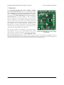
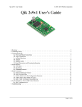
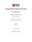
The Pololu dual MC33926 motor driver shield for Arduino
[http://www.pololu.com/product/2503] and its corresponding Arduino
library make it easy to control two bidirectional, brushed DC motors
with an Arduino [http://www.pololu.com/product/2191] or compatible
board, such as the A-Star 32U4 Prime [http://www.pololu.com/category/
165/a-star-32u4-prime]. The board features a pair of Freescale
MC33926 motor drivers, which operate from 5 to 28 V and can
deliver a continuous 3 A per channel, and includes current sense
circuitry, protection resistors, a FET for reverse battery protection,
and logic gates to reduce the required number of I/O pins. It ships
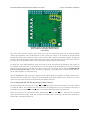
fully populated with its SMD components, including the two
MC33926 ICs, as shown in the picture to the right; stackable
Arduino headers and terminal blocks for connecting motors and
motor power are included but are not soldered in.
This versatile motor driver is intended for a wide range of users,
from beginners who just want a plug-and-play motor control Pololu dual MC33926 motor driver shield
for Arduino.
solution for their Arduinos (and are okay with a little soldering) to
more advanced users who want a dual MC33926 carrier
[http://www.pololu.com/product/1213] that requires fewer I/O pins to control. The Arduino pin mappings can all be
customized if the defaults are not convenient, and the simplified MC33926 control lines are broken out along the left
side of the board, providing a convenient interface point for other microcontroller boards.
1. Overview
Page 2 of 24
Pololu Dual MC33926 Motor Driver Shield User’s Guide
© 2001–2014 Pololu Corporation
1.a. Features
• Wide operating voltage range: 5 – 28 V 1
• Output current: 3 A continuous (5 A peak 2) per motor
• Inputs compatible with both 5 V and 3.3 V systems
• PWM operation up to 20 kHz, which is ultrasonic and allows for quieter
motor operation
• Current sense voltage output proportional to motor current (approx. 525
mV/A)
• Motor indicator LEDs show what the outputs are doing even when no
motor is connected
• Can be used with an Arduino or Arduino clone (through shield headers)
or other microcontroller boards (through 0.1″ header along the left side)
• When used as a shield, the motor power supply can optionally be used to
power the Arduino base as well
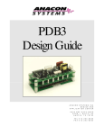
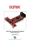
Pololu dual MC33926 motor
driver shield, assembled and
connected to an Arduino
Leonardo.
• Arduino pin mappings can be customized if the default mappings are
not convenient
• Arduino library [http://github.com/pololu/dual-mc33926-motor-shield] makes
it easy to get started using this board as a motor driver shield
• Reverse-voltage protection on motor supply 3
• Robust drivers:
◦ Transient operation (< 500 ms) up to 40 V
◦ Over-current limiting via internal PWM
◦ Over-temperature shutdown and hysteresis
◦ Under-voltage shutdown
◦ Output short-to-ground and short-to-Vcc protection
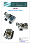
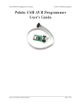
Pololu dual MC33926 motor
driver shield for Arduino, bottom
view with board dimensions.
1
The board supports transient (< 500 ms) operation up to 40V. Operation from 5-8 V reduces maximum continuous
output current (driver performance is derated in this range).
2
Internal peak-current limiting gracefully reduces the output power at load currents above 6.5 A ± 1.5 A. See the
MC33926 datasheet [http://www.pololu.com/file/download/MC33926.pdf?file_id=0J233] (1MB pdf) for more
information.
3
There is no reverse-voltage protection on the logic supply.
1. Overview
Page 3 of 24
Pololu Dual MC33926 Motor Driver Shield User’s Guide
© 2001–2014 Pololu Corporation
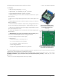
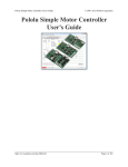
1.b. Included Hardware
This motor driver board ships with all of the surfacemount parts populated. However, soldering is required for
assembly of the included through-hole parts. The
following through-hole parts are included:
• one extended/stackable 1×10 female header (for
Arduino shields)
• two extended/stackable 1×8 female headers (for
Arduino shields)
• two extended/stackable 1×6 female headers (for
Arduino shields)
• three
2-pin,
5 mm
[http://www.pololu.com/product/2440]
terminal
blocks
(for board power and
motor outputs)
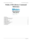
Pololu dual MC33926 motor driver shield for
Arduino with included hardware.
• 25-pin 0.1″ straight breakaway male header
[http://www.pololu.com/product/965]
A 0.1″ shorting block [http://www.pololu.com/product/968] (for optionally supplying shield power to Arduino) is also
included.
You can solder the terminal blocks to the six large through-holes to make your motor and motor power connections,
or you can break off a 12×1 section of the 0.1″ header strip and solder it into the smaller through-holes that border
these larger holes. Note, however, that each header pin pair is only rated for a combined 6 A, so for higher-power
applications, the terminal blocks should be used or thick wires should be soldered directly to the board.
When not using this board as an Arduino shield, you can solder the 0.1″ headers to the logic connections along
the left side of the board to enable use with custom cables [http://www.pololu.com/category/70/crimp-connector-housings] or
solderless breadboards [http://www.pololu.com/category/28/solderless-breadboards], or you can solder wires directly to the
board for more compact installations. Note that motor and motor power connections should not be made through a
breadboard.
The mounting hole is intended for use with #4 screws [http://www.pololu.com/category/101/nuts-and-screws] (not included).
An Arduino [http://www.pololu.com/product/2191] is not included.
1. Overview
Page 4 of 24
Pololu Dual MC33926 Motor Driver Shield User’s Guide
© 2001–2014 Pololu Corporation
2. Contacting Pololu
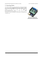
We would be delighted to hear from you about any of your projects and about
your experience with the dual MC33926 motor driver shield for Arduino
[http://www.pololu.com/product/2503]. If you need technical support or have any
feedback you would like to share, you can contact us
[http://www.pololu.com/contact]
directly
or
post
on
our
forum
[http://forum.pololu.com/viewforum.php?f=15]. Tell us what we did well, what we
could improve, what you would like to see in the future, or anything else you
would like to say!
Pololu dual MC33926 motor
driver shield, assembled and
connected to an Arduino Uno R3.
2. Contacting Pololu
Page 5 of 24
Pololu Dual MC33926 Motor Driver Shield User’s Guide
© 2001–2014 Pololu Corporation
3. Getting Started with an Arduino
As with virtually all other Arduino shields, connections between the Arduino and the motor driver are made via
extended stackable headers that must be soldered to the through-holes along the top and bottom edges of the shield.
This section explains how to use this motor driver as an Arduino shield to quickly and easily add control of up to
two DC motors to your Arduino project. For information on how to use this board as a general-purpose motor driver
controlled by something other than an Arduino, see Section 4.
3.a. What You Will Need
The following tools and components are required for getting started using this motor driver as an Arduino shield:
• An Arduino or compatible control board. Using this product as an Arduino shield (rather than a generalpurpose motor driver board) requires an Arduino [http://www.pololu.com/product/2191]. This shield should work
with all Arduinos and Arduino clones that behave like a standard Arduino. You will also need a USB cable for
connecting your Arduino to a computer. We have specifically tested this shield (using our Arduino library) with:
◦ A-Star 32U4 Prime [http://www.pololu.com/category/165/a-star-32u4-prime]
◦ Arduino Uno [http://www.pololu.com/product/2191] (both original and R3)
◦ Arduino Leonardo [http://www.pololu.com/product/2192]
◦ Arduino Due [http://www.pololu.com/product/2193]*
◦ Arduino Mega 2560 [http://www.pololu.com/product/1699]
◦ Arduino Duemilanove (both with ATmega168 and ATmega328P)
• A soldering iron and solder. The through-hole parts included with the shield must be soldered in before you
can plug the shield into an Arduino or before you can connect power and motors. An inexpensive soldering iron
[http://www.pololu.com/product/156] will work, but you might consider investing in a higher-performance, adjustable
soldering iron if you will be doing a lot of work with electronics.
• A power supply. You will need a power supply, such as a battery pack, capable of delivering the current your
motors will draw. See the Power Connections and Considerations portion of Section 3.c for more information
on selecting an appropriate power supply.
• One or two brushed DC motors. This shield is a dual motor driver, so it can independently control two
bidirectional brushed DC motors. See the Motor Connections and Considerations portion of Section 3.c for
more information on selecting appropriate motors.
* Note for Due users: The voltage on the current sense pins will exceed the Due’s 3.3 V limit when the
current draw exceeds ~6 A. The CS circuit has a 1 kΩ resistor in series with the output, which offers some
protection to the analog input, and the driver has over-current protection that kicks in between 5 A and
8 A, so the risk to the Due is low, but if you really want to be safe, you can use a 3.3 V zener diode to
clamp the current sense output voltage to a maximum of ~3.3 V. Alternatively, you can disconnect the
shield’s current sense pins from the Due (and optionally reconnect them through a voltage divider); see
Section 6.a for more information.
3. Getting Started with an Arduino
Page 6 of 24
Pololu Dual MC33926 Motor Driver Shield User’s Guide
© 2001–2014 Pololu Corporation
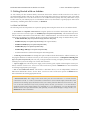
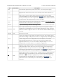
3.b. Assembly for Use as an Arduino Shield
1. Stackable Arduino headers: Before you can use this board as an Arduino shield, you need to solder four
of the five included Arduino header strips to the set of holes highlighted in red in the picture above. The headers
should be oriented so that the female sockets rest on the top side of the shield and face up while the male pins
protrude down through the board, and the solder connections should be made on the underside of the shield. The
newest Arduino boards, including the Uno R3 and the Leonardo, use one 10×1 header, two 8×1 headers, and one
6×1 header, as shown in the left picture below; older Arduino boards use two 8×1 headers and two 6×1 headers,
as shown in the right picture below (the two pairs of pins highlighted in darker red should not be populated if
you are using this board with an older Arduino that does not support these additional pins). Please make sure
you solder the appropriate headers for your particular Arduino!
2. Motor and power connections: The six large holes/twelve small holes on the right side of the board,
highlighted in yellow in the above diagram, are the motor outputs and power inputs. You can optionally solder
the included 5mm-pitch terminal blocks to the six large holes to enable temporary motor and motor power
3. Getting Started with an Arduino
Page 7 of 24
Pololu Dual MC33926 Motor Driver Shield User’s Guide
© 2001–2014 Pololu Corporation
connections, or you can break off a 12×1 section of the included 0.1″ header strip and solder it into the smaller
through-holes that border the six large motor and motor power pads. Note, however, that each header pin pair
is only rated for a combined 6 A, so for higher-power applications, the terminal blocks should be used or thick
wires with high-current connectors [http://www.pololu.com/product/925] should be soldered directly to the board.
The smaller holes are intended only for 0.1″ header pins, not for the terminal blocks!
3. Arduino power jumper: If you want the option of powering your Arduino and motor shield from the same
source, you can solder a 2×1 piece of the included 0.1″ male header strip to two the pins highlighted in orange
in the above picture. Shorting across these pins with the included shorting block will connect the shield power
to the Arduino’s VIN pin. You should not use this to power the shield from the Arduino as this connection is
not designed to handle high currents, and you must never supply power to the Arduino’s VIN pin or power jack
while this shorting block is in place, because it will create a short between the shield power supply and the
Arduino power supply and will likely permanently damage something.
4. Arduino pin breakout points: The shield provides a secondary access point for each Arduino pin, divided
into two rows of pins spaced on a 0.1″ grid (unlike the standard Arduino pins, which have a half-pin offset
introduced by the gap in the top row). You can optionally solder 0.1″ female headers (not included) to these pins.
Note that the SCL and SDA breakouts are top-layer pads only, not through-holes, due to the close proximity of
Arduino pins below.
The other through-holes on the shield are used for more advanced things like customizing the Arduino pin mappings
or using the board with other microcontrollers. They are not necessary for getting started using this shield with an
Arduino, and they are discussed in more detail later in this guide.
3.c. Shield Connections: Signals, Power, and Motors
Using the dual MC33926 motor driver shield with an Arduino (shield and Arduino powered
separately).
All of the necessary logic connections between the Arduino and the motor driver shield, including VDD, are made
automatically when the shield is plugged into the Arduino. However, the shield’s motor power must be supplied
3. Getting Started with an Arduino
Page 8 of 24
Pololu Dual MC33926 Motor Driver Shield User’s Guide
© 2001–2014 Pololu Corporation
directly to the shield itself via its large, high-current VIN and GND pads. The motor channels, located on either side
of these power pins, can each be used to independently control a bidirectional brushed DC motor. Each motor channel
is comprised of a pair of pins—MxA and MxB—that connect to the two terminals of a DC motor and can deliver
a continuous 3 A (5 A peak). The picture above shows the typical connections involved in using this board as an
Arduino shield. In the depicted configuration, the Arduino is powered separately from the shield, such as through its
USB connector or power jack.
Default Arduino Pin Mappings
The following table shows how the shield connects your Arduino’s pins to the motor drivers’ pins:
Arduino Pin Shield Pin Name
Basic Function
Digital 4
D2 (or nD2)
Tri-state disables both outputs of both motor channels when LOW;
toggling resets latched driver fault condition
Digital 7
M1DIR
Motor 1 direction input
Digital 8
M2DIR
Motor 2 direction input
Digital 9
M1PWM
Motor 1 speed input
Digital 10
M2PWM
Motor 2 speed input
Digital 12
SF (or nSF)
Status flag indicator (LOW indicates fault)
Analog 0
M1FB
Motor 1 current sense output (approx. 525 mV/A)
Analog 1
M2FB
Motor 2 current sense output (approx. 525 mV/A)
See Section 4.b for more detailed descriptions of the shield pins and a motor control truth table. See
Section 5 for a schematic diagram of the shield. See Section 6.a for instructions on how to customize
your board’s Arduino pin mappings if the above defaults are not convenient.
3. Getting Started with an Arduino
Page 9 of 24
Pololu Dual MC33926 Motor Driver Shield User’s Guide
© 2001–2014 Pololu Corporation
Power Connections
Dual MC33926 motor driver shield power buses when connected to an
Arduino.
In the shield’s default state, the motor driver shield and Arduino are powered separately. When used this way, the
Arduino must be powered via USB, its power jack, or its VIN pin, and the shield must be supplied with 5 to 28 V
through the large VIN and GND pads on the right side of the board. Attempting to power the shield through other
means, such as from the Arduino or through the small VOUT pin, can permanently damage both the Arduino and the
shield (only the large power traces on the right side of the shield are designed to handle the high currents involved in
powering motors). A high-side reverse-voltage protection MOSFET prevents the shield from being damaged if motor
power is inadvertently connected backwards. Logic power, VDD, is automatically supplied by the Arduino.
3. Getting Started with an Arduino
Page 10 of 24
Pololu Dual MC33926 Motor Driver Shield User’s Guide
© 2001–2014 Pololu Corporation
Using the dual MC33926 motor driver shield with an Arduino (Arduino powered by shield).
It is also possible to power your Arduino directly from the motor shield, as shown in the diagram above, which
eliminates the need for a separate Arduino power supply. When the ARDVIN=VOUT shorting block is in place, the
shield’s reverse-protected input power, VOUT, is connected to the Arduino’s VIN pin. (When power is connected
properly, VOUT is essentially the same as the shield’s VIN.) The Arduino’s power jack must remain disconnected at
all times in this configuration.
Warning: When powering the Arduino from the motor shield, you must never connect a different power
supply to the Arduino’s VIN pin or plug a power supply into the Arduino’s power jack, as doing so will
create a short between the shield’s power supply and the Arduino’s power supply that could permanently
damage both the Arduino and the motor shield. In this case, it is also important that your shield power
supply is an acceptable voltage for your Arduino, so the full shield operating voltage range of 5 – 28 V
probably will not be available. For example, the recommended operating voltage of the Arduino Uno is 7
– 12 V.
Power Considerations
The shield operates from 5 to 28 V, but it can tolerate transient voltages (shorter than 500 ms in duration) of up to
40 V, which means it is generally safe to power this board with a 24 V battery. At voltages between 5 and 8 V, the
shield performance is derated, and the maximum achievable continuous output current will be decreased (according
to the MC33926 datasheet, H-bridge MOSFET on-resistances might increase by 50% in this “quasi-functional”
performance region). The shield operating voltage range is much wider than the typical Arduino operating voltage
range, so if you are using the shield to power your Arduino, please ensure that your voltage source is within acceptable
limits for your Arduino as well as the shield.
It is important that you use a power source that is capable of delivering the current your motors will require. For
example, alkaline cells are typically poor choices for high-current applications, and you should almost never use a
3. Getting Started with an Arduino
Page 11 of 24
Pololu Dual MC33926 Motor Driver Shield User’s Guide
© 2001–2014 Pololu Corporation
9V battery (the rectangular type with both terminals on the same side) as your motor power supply. We recommend
NiMH batteries [http://www.pololu.com/category/54/batteries], lithium-based rechargeable batteries (if you have a good
charger and adequately understand the dangers of using them improperly), or a power adapter with an appropriate
power rating. The current draw is ultimately a function of your motors, your operating voltage, and your motor load,
but the driver is capable of delivering a continuous 6 A (3 A per channel), and it can deliver in excess of 10 A before
the internal current limiting is activated.
Shield Power Dissipation
Each MC33926 motor driver IC has a maximum continuous current rating of 5 A. However, the actual current it can
deliver depends on how well you can keep it cool. The shield’s printed circuit board is designed to draw heat out of
the motor driver chips, but performance can be improved by adding heat sinks.
Unlike other H-Bridges, the MC33926 has a feature that allows it to gracefully reduce current as the current exceeds
5 A or as the chip temperature approaches its limit. This means that if you push the chip close to its limit, you will
see less power to the motor, but it might allow you to avoid a complete shutdown.
We tested the shield at room temperature with no forced air flow or heat sinks. In our tests, the shield was able to
deliver 5 A to both channels simultaneously for 10 s before the thermal protection started reducing the current. The
shield delivered 4 A on both channels for 37 s, and at 3 A it was able to operate continuously for over 10 minutes
without triggering current limiting or thermal protection.
Our tests were conducted at 100% duty cycle; PWMing the motor will introduce additional heating proportional to
the frequency.
This product can get hot enough to burn you long before the chip overheats. Take care when handling this
product and other components connected to it.
Motor Considerations
If your motor has a stall current over the driver’s continuous current rating of 3 A per channel, we recommend
you take extra steps to make sure that your motor will not be exposed to loads that will cause it to exceed 3 A for
prolonged periods of time (or you take extra steps to keep the motor drivers cool, such as increasing air flow or adding
heat sinks). Exceeding 3 A for long durations should not damage the shield, but it will eventually activate the driver’s
thermal protection, which might result in inadequate performance for your application.
It is not unusual for the stall current of a motor to be an order of magnitude (10×) higher than its freerun current. If you do not know your motor’s stall current, you can approximate it by measuring the
current it draws while held stalled at a lower voltage (such as when powered from a single battery cell)
and then scaling that value linearly with voltage. For example, the stall current of a motor at 6 V is
six times the stall current of that motor at 1 V. Another, less accurate method is to use a multimeter
to measure the resistance between the motor terminals and then use Ohm’s law to compute the stall
current I at voltage V: I = V/R. This last method generally is not as reliable because it can be difficult
to measure such small resistances accurately.
Occasionally, electrical noise from a motor can interfere with the rest of the system. This can depend on a number of
factors, including the power supply, system wiring, and the quality of the motor. If you notice parts of your system
behaving strangely when the motor is active, first double-check that your power supply is adequate, then consider
taking the following steps to decrease the impact of motor-induced electrical noise on the rest of your system:
3. Getting Started with an Arduino
Page 12 of 24
Pololu Dual MC33926 Motor Driver Shield User’s Guide
© 2001–2014 Pololu Corporation
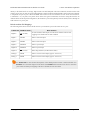
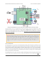
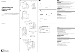
1. Solder a 0.1 µF ceramic capacitor [http://www.pololu.com/product/1166]
across the terminals of your motors, or solder one capacitor from each
terminal to the motor case (see the pictures to the right). For the greatest
noise suppression, you can use three capacitors per motor (one across the
terminals and one from each terminal to the case).
2. Make your motor leads as thick and as short as possible, and twist them
around each other. It is also beneficial to do this with your power supply
leads.
Motor with one 0.1 uF capacitor
soldered across its terminals.
3. Route your motor and power leads away from your logic connections if
possible.
4. Place decoupling capacitors (also known as “bypass capacitors”)
across power and ground near any electronics you want to isolate from
noise. These can typically range from 10 uF to a few hundred uF.
3.d. Programming Your Arduino
Motor with two 0.1 uF capacitors
soldered from its terminals to its
case.
Our Arduino library for the dual MC33926 motor driver shield makes it easy
to get started writing your Arduino sketches. A link to download the library, installation instructions, and the library
command reference can be found on the library’s github page [http://github.com/pololu/dual-mc33926-motor-shield]. Once
installed, we recommend you try out the example sketch by selecting
File > Examples > DualMC33926MotorShield > Demo
from the Arduino IDE, or by copying the following code into a new sketch:
#include "DualMC33926MotorShield.h"
DualMC33926MotorShield md;
void stopIfFault()
{
if (md.getFault())
{
Serial.println("fault");
while(1);
}
}
void setup()
{
Serial.begin(115200);
Serial.println("Dual MC33926 Motor Shield");
md.init();
}
void loop()
{
for (int i = 0; i <= 400; i++)
{
md.setM1Speed(i);
stopIfFault();
if (abs(i)%200 == 100)
{
Serial.print("M1 current: ");
Serial.println(md.getM1CurrentMilliamps());
}
delay(2);
}
for (int i = 400; i >= -400; i--)
{
3. Getting Started with an Arduino
Page 13 of 24
Pololu Dual MC33926 Motor Driver Shield User’s Guide
}
© 2001–2014 Pololu Corporation
md.setM1Speed(i);
stopIfFault();
if (abs(i)%200 == 100)
{
Serial.print("M1 current: ");
Serial.println(md.getM1CurrentMilliamps());
}
delay(2);
for (int i = -400; i <= 0; i++)
{
md.setM1Speed(i);
stopIfFault();
if (abs(i)%200 == 100)
{
Serial.print("M1 current: ");
Serial.println(md.getM1CurrentMilliamps());
}
delay(2);
}
for (int i = 0; i <= 400; i++)
{
md.setM2Speed(i);
stopIfFault();
if (abs(i)%200 == 100)
{
Serial.print("M2 current: ");
Serial.println(md.getM2CurrentMilliamps());
}
delay(2);
}
for (int i = 400; i >= -400; i--)
{
md.setM2Speed(i);
stopIfFault();
if (abs(i)%200 == 100)
{
Serial.print("M2 current: ");
Serial.println(md.getM2CurrentMilliamps());
}
delay(2);
}
}
for (int i = -400; i <= 0; i++)
{
md.setM2Speed(i);
stopIfFault();
if (abs(i)%200 == 100)
{
Serial.print("M2 current: ");
Serial.println(md.getM2CurrentMilliamps());
}
delay(2);
}
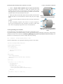
This example ramps motor 1 speed from zero to max speed forward, to max speed reverse, and back to zero again
over a period of about 3 s, while checking for motor faults and periodically printing the motor current to the serial
monitor. It then performs the same process on motor 2 before repeating all over again.
Note: Even if you do not have any motors yet, you can still try out this sketch and use the motor
indicator LEDs for feedback that the shield is working properly.
3. Getting Started with an Arduino
Page 14 of 24
Pololu Dual MC33926 Motor Driver Shield User’s Guide
© 2001–2014 Pololu Corporation
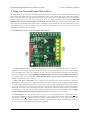
4. Using as a General-Purpose Motor Driver
MC33926 motor driver control lines and output signals are available via the set of pins along the left side of the board,
which means this shield can be used as a general-purpose motor driver controlled by devices other than Arduinos.
This section explains how to use the dual MC33926 motor driver shield this way and provides some basic information
about the motor driver pins to help get you started. However, we strongly encourage you to consult the MC33926
datasheet [http://www.pololu.com/file/download/MC33926.pdf?file_id=0J233] (1MB pdf) for detailed pin descriptions, truth
tables, and electrical characteristics. This shield is essentially a breakout board for two MC33926 motor driver ICs
with additional logic circuitry to simplify the motor control, so the datasheet is your best resource for answering
questions not covered by this user’s guide.
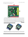
4.a. Assembly for Use as a General-Purpose Motor Driver
1. Logic connections: The 11 small holes along the left side of the board, highlighted in red in the above
diagram, are used to interface with the motor drivers. You can optionally solder a 11×1 piece of the included
0.1″ male header strip to these pins. Soldering the pins so they protrude down allows the logic side of the motor
driver to be plugged into a standard solderless breadboard [http://www.pololu.com/category/28/solderless-breadboards]
or perfboard. You can also solder 0.1″ female headers [http://www.pololu.com/category/50/0.100-in-2.54-mm-femaleheaders] or custom connectors to these pins.
2. Motor and power connections: The six large holes/twelve small holes on the right side of the board,
highlighted in yellow in the above diagram, are the motor outputs and power inputs. You can optionally solder
the included 5mm-pitch terminal blocks to the board to enable temporary motor and motor power connections,
or you can break off an 12×1 section of the included 0.1″ header strip and solder it into the smaller through-holes
that border the six large motor and motor power pads. Note, however, that each header pin pair is only rated for
a combined 6 A, so for higher-power applications, the terminal blocks should be used or thick wires with highcurrent connectors [http://www.pololu.com/product/925] should be soldered directly to the board.
3. Enable Jumper: You can optionally solder a wire or a 2×1 piece of the included 0.1″ male header strip to
the two pins highlighted in orange in the above diagram to create a board enable jumper. The left pin is D2, and
the right pin is VDD. D2 is internally pulled low, which tri-state disables the motor driver outputs and allows any
connected motor to coast. In order to enable the board, this pin must be driven high, either through a connection
to an I/O line or by connecting it to the neighboring VDD pin.
4. Using as a General-Purpose Motor Driver
Page 15 of 24
Pololu Dual MC33926 Motor Driver Shield User’s Guide
© 2001–2014 Pololu Corporation
With the exception of the pins labeled “D2 1=2” and “SF 1=2”, all of the through-holes not highlighted in the above
diagram are only relevant when using this driver as an Arduino shield. The “D2 1=2” and “SF 1=2” pins are explained
in the “Pinout” portion of Section 4.b, but they will not be needed in typical applications and can generally be ignored.
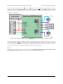
4.b. Board Connections
Using the dual MC33926 motor driver shield with a microcontroller (gray connections are
optional).
The above diagram shows the minimum connections typically required to interface this motor driver with a
microcontroller. Note that D2 is internally pulled low, which disables the motor outputs; it must either be connected
to an I/O line (for dynamic control) or soldered to the neighboring VDD pin to enable the drivers. Only two pins are
required per motor: direction control with MxDIR and speed control with MxPWM.
Pinout
The following table explains the board pins in detail. See the MC33926 datasheet [http://www.pololu.com/file/download/
MC33926.pdf?file_id=0J233] (1MB pdf) for even more detailed information about these pins.
4. Using as a General-Purpose Motor Driver
Page 16 of 24
Pololu Dual MC33926 Motor Driver Shield User’s Guide
PIN
Default State
© 2001–2014 Pololu Corporation
Description
VIN
The connection point for the positive side of the 5 – 28 V motor power supply.
VDD
The connection point for the positive side of the logic power supply (typically 2.5 –
5 V).
VOUT
This pin gives you access to the motor power supply after the reverse-voltage
protection MOSFET (see the board schematic in Section 5). It can be used to supply
reverse-protected power to other components in the system, but it should not be used
for high currents. This pin should only be used as an output.
GND
Ground connection points for logic and motor power supplies. The controlling device
and the motor driver must share a common ground.
MxA/B
Output of half-bridge A/B. Each half-bridge connects to one terminal of a DC motor.
MxPWM LOW
Pulse-width modulation input: a PWM signal on this pin corresponds to a PWM
output on the corresponding driver’s motor outputs. When this pin is low, the motor
brakes low. When it is high, the motor is on. The maximum allowed PWM frequency
is 20 kHz.
MxDIR
Motor direction input.
LOW
MxFB
Current sense output. The pin voltage is roughly 525 mV per amp of output current.
(Note that the voltage on this pin can exceed 3.3 V at high currents, which might make
it unsafe to connect to 3.3 V analog inputs. The CS circuit has a 1 kΩ resistor in series
with the output, which offers some protection, and the driver has over-current
protection that kicks in between 5 A and 8 A, so the risk is low, but the safest
approach would be to use a 3.3 V zener diode to clamp the output to ~3.3 V or a
voltage divider to scale the output over a range that is appropriate.)
SF
HIGH
Diagnostic output. When both drivers are functioning normally, this pin is internally
pulled high. When a driver fault occurs, the IC drives this pin low and the motor
outputs are disabled. This pin will also be low whenever D2 is low. Note that the
status flag lines from both drivers are tied together. See Section 6.b for information on
how to individually access the status flag pins (this is typically not necessary).
LOW
Disables the motor driver outputs when low. A PWM on this pin with MxPWM held
high results in drive-coast operation (vs. drive-brake when the PWM is applied to
MxPWM and D2 is held high). Toggling this pin will clear any latched faults. Note
that the disable lines from both drivers are tied together. See Section 6.b for
information on how to individually access the disable pins (this is typically not
necessary).
D2
4. Using as a General-Purpose Motor Driver
Page 17 of 24
Pololu Dual MC33926 Motor Driver Shield User’s Guide
© 2001–2014 Pololu Corporation
Simplified Motor Control Truth Table
Inputs
Outputs
D2 MxPWM MxDIR MxA MxB SF
Mode
H
H
L
H
L
H
forward
H
H
H
L
H
H
reverse
H
L
X
L
L
H
brake
L
X
X
Z
Z
L
coast
L = LOW, H = HIGH, X = HIGH or LOW, Z = high impedance
The above table assumes there are currently no driver faults.
Power Considerations
Dual MC33926 motor driver shield power buses when not used with an
Arduino.
The shield must be supplied with 5 to 28 V through the large VIN and GND pads on the right side of the
board. A high-side reverse-voltage protection MOSFET prevents the shield from being damaged if shield power is
inadvertently connected backwards.
It is important that you use a power source that is capable of delivering the current your motors will require. For
example, alkaline cells are typically poor choices for high-current applications, and you should almost never use a 9V
battery (the rectangular type with both terminals on the same side) as your motor power supply.
Logic power at the same level as your controlling device should be supplied to the VDD pin. This will typically be
between 2.5 and 5 V.
Please see the MC33926 datasheet and Section 3.c for more power considerations and for information about shield
power dissipation.
4. Using as a General-Purpose Motor Driver
Page 18 of 24
Pololu Dual MC33926 Motor Driver Shield User’s Guide
© 2001–2014 Pololu Corporation
Motor Considerations
The motor considerations are the same as those detailed in Section 3.c.
4. Using as a General-Purpose Motor Driver
Page 19 of 24
Pololu Dual MC33926 Motor Driver Shield User’s Guide
© 2001–2014 Pololu Corporation
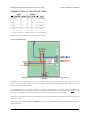
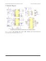
5. Schematic Diagram
Schematic diagram for the Dual MC33926 Motor Driver Shield for Arduino.
PDF of schematic: dual MC33926 motor driver shield schematic
dual_mc33926_shield_schematic.pdf?file_id=0J559] (350k pdf).
5. Schematic Diagram
[http://www.pololu.com/file/download/
Page 20 of 24
Pololu Dual MC33926 Motor Driver Shield User’s Guide
© 2001–2014 Pololu Corporation
6. Customizing the Shield
This motor driver shield has several features that will not be useful in a typical application but that might benefit an
advanced user. This section explains how to modify the shield from its default state to access these features.
6.a. Remapping the Arduino Connections
For some applications, this shield’s default Arduino pin mappings might not be convenient. For example, maybe you
want to use the 16-bit Timer 1 for making music on a buzzer and would rather use PWMs from Timer 0 to control
your motor speed. Or maybe you don’t care about monitoring the motor current and would rather use all of your
analog inputs for reading sensors. With this in mind, we designed the shield to have break points in the connection
between the Arduino pins and the motor drivers. It is easy to cut the connections at these points and establish new
connections to replace the broken ones if desired.
The following two diagrams show the default pin mappings:
Dual MC33926 motor driver shield
Arduino pin mappings for speed,
direction, and current feedback.
Dual MC33926 motor driver shield
Arduino pin mappings for driver disable
and fault status.
The connections between the Arduino pins and the MC33926 motor driver pins are each made through a pair of 0.1″spaced holes that are connected on the underside of the shield by a thin trace:
6. Customizing the Shield
Page 21 of 24
Pololu Dual MC33926 Motor Driver Shield User’s Guide
© 2001–2014 Pololu Corporation
Cuttable traces on the dual MC33926 motor
driver shield for changing default Arduino
connections.
The yellow boxes mark the locations where traces can be cut on the underside of the PCB to remap the default
Arduino pin assignments. The top through-hole of each vertical pair connects to the Arduino pin and the bottom
through-hole connects to the motor driver pin. For the A0 and A1 pairs, which are oriented horizontally, the right pins
connect to the Arduino and the left pins connect to the motor drivers (when the shield is viewed from the top side). In
the figure above, the pin number label is next to the pin that connects directly to the Arduino.
To change one of the default mappings, simply use a knife to cut the trace between the appropriate pair of holes on
the underside of the PCB (there is no connection to cut on the topside of the PCB) and run a wire from a different
Arduino pin to the bottom (or left) hole of the pair to create a new connection. You can later use shorting blocks
[http://www.pololu.com/product/968] to restore the default pin mapping if you populate the severed hole pairs with 2×1
pieces of the included 0.1″ male header strip.
The pins highlighted in blue in the above diagram are the Arduino header pins and their secondary breakout rows.
These pins are also connected by a single trace on the underside of the PCB, and these traces can also be cut if you
wish to sever the connection between the breakout point and the header pin.
6.b. Accessing nD2 and nSF Pins Separately for Each Channel
The shield combines the two motor driver chips’ D2 and SF pins in order to decrease the number of I/O lines required
to control the motors. The combined lines are sufficient for most applications, but you can modify the board to get
independent access to the MxD2 and MxSF pins if you want the additional control and information.
There are two pairs of 0.1″-spaced holes on the shield labeled “D2 1=2” and “SF 1=2”. These pairs are connected
on the underside of the PCB by a thin trace, with the holes labeled “M1” connecting to the M1 driver and the holes
labeled “M2” connecting to M2 driver.
6. Customizing the Shield
Page 22 of 24
Pololu Dual MC33926 Motor Driver Shield User’s Guide
© 2001–2014 Pololu Corporation
Cuttable traces on the dual MC33926 motor
driver shield for accessing nD2 and nSF
separately on each driver IC.
The following diagrams shows the relevant sections of the board schematic:
To separately access both the pins, you can use a knife to cut the trace between the through-hole pair.
For D2, note that once the connection between the two pins is severed, only M1D2 will have the protection resistor
between it and the logic connections.
For SF, note that once the connection between the two pins is severed, only M1SF will have the required pull-up
resistor and the protection resistor between it and the logic connections; you will need to add a separate pull-up
resistor and protection resistor for M2SF.
6. Customizing the Shield
Page 23 of 24
Pololu Dual MC33926 Motor Driver Shield User’s Guide
© 2001–2014 Pololu Corporation
You can later use a shorting block to restore the default combined D2 or SF lines if you populate the severed hole pair
with a 2×1 piece of the included 0.1″ male header strip.
6. Customizing the Shield
Page 24 of 24