1
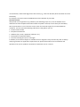
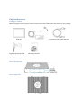
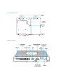
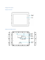
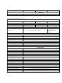
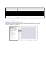
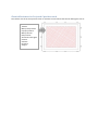
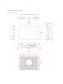
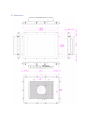
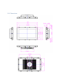
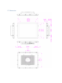
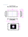
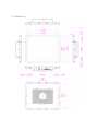
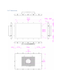
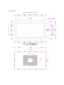
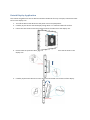
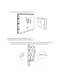
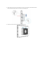
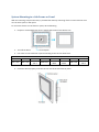
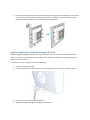
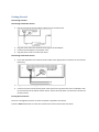
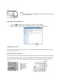
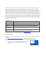
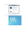
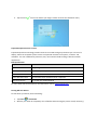
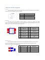
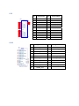
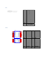
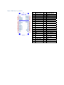
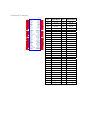
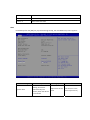
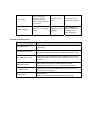
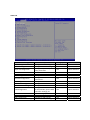
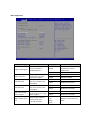
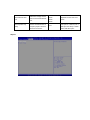
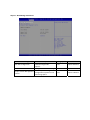
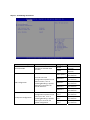
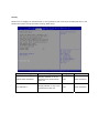
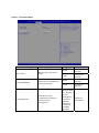
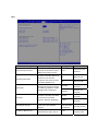
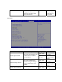
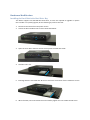
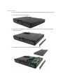
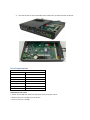
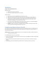
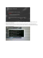
User Manual Standard HMI Touch Panels TableofContents Safety Information ........................................................................................................................................ 4 Important Information .................................................................................................................................. 5 Physical Overview ......................................................................................................................................... 8 Package Contents ...................................................................................................................................... 8 Box PC Description .................................................................................................................................... 8 Box PC Front View ................................................................................................................................. 8 Box PC Top View ................................................................................................................................... 8 Box PC Bottom View ............................................................................................................................. 9 Box PC I/O View .................................................................................................................................... 9 Display Description ................................................................................................................................. 10 Display Front View .............................................................................................................................. 10 Display Side and Rear Views ............................................................................................................... 10 Characteristics ............................................................................................................................................. 11 Panel PC Characteristics (4:3) ................................................................................................................. 11 Panel PC Characteristics (16:9) ............................................................................................................... 12 Environmental Characteristics .................................................................................................................... 13 Chemical Resistance for Resistive Touch ................................................................................................ 13 Chemical Resistance for Projected Capacitive touch .............................................................................. 14 Mechanical Dimensions .............................................................................................................................. 15 12.1” Dimensions .................................................................................................................................... 15 15” Dimensions ....................................................................................................................................... 16 15.6” Dimensions .................................................................................................................................... 17 17” Dimensions ....................................................................................................................................... 18 18.5” Dimensions .................................................................................................................................... 19 19” Dimensions ....................................................................................................................................... 20 21.5” Dimensions .................................................................................................................................... 21 24” Dimensions ....................................................................................................................................... 22 Detach Display Application ......................................................................................................................... 23 Attaching Box PC to the Display Unit .......................................................................................................... 24 System Mounting to a Sub Frame or Panel ................................................................................................ 26 Engineering Display Stand Mounting to the Unit ....................................................................................... 27 Getting Started ............................................................................................................................................ 28 Connectors and Pin Assignment ................................................................................................................. 33 Power ...................................................................................................................................................... 33 Ethernet .................................................................................................................................................. 33 Serial Device ............................................................................................................................................ 33 USB .......................................................................................................................................................... 34 HDMI ....................................................................................................................................................... 34 VGA ......................................................................................................................................................... 35 SATA ........................................................................................................................................................ 35 Mini‐PCIE Slot for mSATA ........................................................................................................................ 36 eDP Board Connector .............................................................................................................................. 37 Configuration of the BIOS ........................................................................................................................... 38 Hardware Modification ............................................................................................................................... 52 Installing the Hard Disk in the Hard Drive Bay ........................................................................................ 52 Service Access ......................................................................................................................................... 53 Fuse Replacement ....................................................................................................................................... 54 Maintenance ............................................................................................................................................... 55 Using Recovery Wizard to Restore Panel PC ............................................................................................... 55 AIS Support ................................................................................................................................................. 57 New Product Satisfaction Return ................................................................................................................ 57 SafetyInformation Warning! Always completely disconnect the power cord from your chassis whenever you work with the hardware. Do not make connections while the power is on. Sensitive electronic components can be damaged by sudden power surges. Only experienced electronics personnel should open the PC chassis. Caution! Always ground yourself to remove any static charge before touching the CPU card. Modern electronic devices are very sensitive to static electric charges. As a safety precaution, use a grounding wrist strap at all times. Place all electronic components in a static‐dissipative surface or static‐shielded bag when they are not in the chassis. Safety Precautions Please read these safety instructions carefully. Please keep this user's manual for later reference. Please disconnect this equipment from any AC outlet before cleaning. Do not use liquid or spray detergents for cleaning. Use a damp cloth. For pluggable equipment, the power outlet must be installed near the equipment and must be easily accessible. Keep this equipment away from humidity. Put this equipment on a reliable surface during installation. Dropping it or letting it fall could cause damage. The openings on the enclosure are for air convection and to protect the equipment from overheating. DO NOT COVER THE OPENINGS. Make sure the voltage of the power source is correct before connecting the equipment to the power outlet. Position the power cord so that people cannot step on it. Do not place anything over the power cord. All cautions and warnings on the equipment should be noted. If the equipment is not used for a long time, disconnect it from the power source to avoid damage by transient over‐voltage. Never pour any liquid into an opening. This could cause fire or electrical shock. Never open the equipment. For safety reasons, only qualified service personnel should open the equipment. If any of the following situations arises, get the equipment checked by service personnel: o The power cord or plug is damaged. o Liquid has penetrated into the equipment. o The equipment has been exposed to moisture. o The equipment does not work well or you cannot get it to work according to the user’s manual. o The equipment has been dropped and damaged. o The equipment has obvious signs of breakage. Do not leave this equipment in an uncontrolled environment where the storage temperature is below ‐20° C (‐4°F) or above 60° C (140° F). It may damage the equipment. CAUTION – Use the recommended mounting apparatus to avoid risk of injury. WARNING – Only use the connection cords that come with the product. When in doubt, please contact the manufacturer. WARNING – Ground against electrostatic damage to the device by taking the following preventive steps: o Cover workstations with approved anti‐static material. Use a wrist strap connected to a work surface and properly grounded tools and equipment. o Use anti‐static mats, heel straps, or air ionizer for added protection. o Handle electrostatic‐sensitive components, PCB’s and assemblies by the case or the edge of the board. o Avoid contact with pins, leads, or circuitry. o Turn off power and input signals before inserting and removing connectors or test equipment. o Keep the work area free of non‐conductive materials, such as ordinary plastic assembly aids and Styrofoam. o Use filed service tools, such as cutters, screwdrivers, and vacuum cleaners that are conductive. o Always lay drivers and PCB’s with the component side down on anti‐static foam. Intended Use Premium HMI Touch Panels are primarily intended for use in HMI, SCADA & MES applications. They are suitable for use in industrial environments and are typically used for automation purposes. ImportantInformation Federal Communications Commission Radio Frequency Interface Statement – For USA This device complies with part 15 FCC rules. Operation is subject to the following two conditions: This device may not cause harmful interference. This device must accept any interference received including interference that may cause undesired operation. This equipment has been tested and found to comply with the limits for a class "A" digital device, pursuant to part 15 of the FCC rules. These limits are designed to provide reasonable protection against harmful interference when the equipment is operated in a commercial environment. This equipment generates, uses, and can radiate radio frequency energy and, if not installed and used in accordance with the instruction manual, may cause harmful interference to radio communications. Operation of this equipment in a residential area is likely to cause harmful interference in which case the user will be required to correct the interference at him own expense. Certifications and Standards Agency Standard for Marking Description UL/cUL/CB 61010 Safety of electrical equipment; measurement, control, industrial process, and laboratory electrical equipment. UL/cUL/CB 62368 Safety of electronic equipment; audio, video, information and communication technology, and business and office machines. Copyright Notice No part of this document may be reproduced, copied, translated, or transmitted in any form or by any means, electronic or mechanical, for any purpose, without the prior written permission of the original manufacturer. Trademark Acknowledgement Brand and product names are trademarks or registered trademarks of their respective owners. Disclaimer We reserves the right to make changes, without notice, to any product, including circuits and/or software described or contained in this manual in order to improve design and/or performance. We assume no responsibility or liability for the use of the described product(s), conveys no license or title under any patent, copyright, or masks work rights to these products, and makes no representations or warranties that these products are free from patent, copyright, or mask work right infringement, unless otherwise specified. Applications that are described in this manual are for illustration purposes only. We make no representation or guarantee that such application will be suitable for the specified use without further testing or modification. Warranty Our warranty guarantees that each of its products will be free from material and workmanship defects for a period of one year from the invoice date. If the customer discovers a defect, we will, at his/her option, repair or replace the defective product at no charge to the customer, provide it is returned during the warranty period of one year, with transportation charges prepaid. The returned product must be properly packaged in its original packaging to obtain warranty service. If the serial number and the product shipping data differ by over 30 days, the in‐warranty service will be made according to the shipping date. In the serial numbers the third and fourth two digits give the year of manufacture, and the fifth digit means the month (e. g., with A for October, B for November and C for December). For example, the serial number 1W14Axxxxxxxx means October of year 2014. Customer Service We provide a service guide for any problem by the following steps: First, visit the website of our distributor to find the update information about the product. Second, contact with your distributor, sales representative, or our customer service center for technical support if you need additional assistance. You may need the following information ready before you call: Product serial number Peripheral attachments Software (OS, version, application software, etc.) Description of complete problem The exact wording of any error messages In addition, free technical support is available from our engineers every business day. We are always ready to give advice on application requirements or specific information on the installation and operation of any of our products. Please do not hesitate to call or e‐mail us. PhysicalOverview PackageContents Before using this Panel PC, please make sure that all the items listed below are present in your package: Panel PC Engineering display stand AC adapter 2 x Power Cord (EU and USA type) Mounting Fasteners BoxPCDescription BoxPCFrontView BoxPCTopView BoxPCBottomView BoxPCI/OView DisplayDescription DisplayFrontView DisplaySideandRearViews Characteristics PanelPCCharacteristics(4:3) Part Number HMI‐TSND0U‐12SR‐X00H HMI‐TSND0U‐15SR‐X00H 12.1" / XGA, 1024 x 768 15" / XGA, 1024 x 768 17" / SXGA, 1280 x 1024 500 nits / 500 cd/m² 400 nits / 400 cd/m² 350 nits / 350 cd/m² Display Size in inches / resolution in pixels Brightness / luminance MTBF of backlight LED‐backlight up to 100,000 hours in Eco mode Touchscreen Single‐touch (resistive analog) System Hardware Processor Intel® Atom™ E3845 Processor; 2M Cache, 1.91 GHz, 10 W maximum TDP Cores / speed Memory / # of slots Graphics / video 4 / 1.91 GHz From 4 GB DDR3L 1333 SDRAM, configurable up to 8 GB / 2 slots Intel HD graphics; DirectX 11.1, OpenCL / GL, and 4K videos Quick Sync encoder Drives Mass storage 1 x 180 GB SSD Secondary storage 32 GB m‐SATA SSD Optical drives Connection via USB port Interface Ports Ethernet 2 x Ethernet TCP/IP ‐ RJ45, isolated USB 4 x USB 2.0 Serial COM1: RS‐232/422/485, isolated Graphics / video 1 x VGA; 1 x HDMI Audio 1 x Line‐in, 1 x Line‐out General Features Operating system HMI‐TSND0U‐17SR‐X00H Windows Embedded 7 32 or 64‐bit / Windows Embedded 8 Current supply 24 V DC; 9.6 to 28.8 V, isolated Bezel / housing Stainless steel / aluminum Mounting options Panel PC: Panel / wall mount; Box PC: Wall / DIN rail mount Packages / bundles Packages with Wonderware InTouch, ready‐to‐use HMI software (optional) Environmental / Ambient Conditions Degree of protection / thermal Front: IP66; Rear: IP20 / Fanless Electromagnetic compatibility CE, FCC A, EN 61000‐6‐4, EN 61000‐6‐3, CISPR22, RoHS Vibration during operation Tested according to DIN IEC 60068‐2‐64: 5 ‐ 500 Hz: 1 Grms Shock during operation Tested according to DIN IEC 60068‐2‐27: 15 gn for 11 ms Ambient temperature 0...50˚C (32...122˚F) Relative humidity Certifications / regulations 30% to 95% at 40°C (no condensation) UL/cUL/CB 62368, UL/cUL/CB 61010, IP66, NEMA 4/4X Physical Specifications Operator panel / cut‐out (W x H) Installation dimensions (W x H x D) 297 x 236 mm 387 x 291 mm 408 x 313 mm 313.5 x 246 x 79.6 mm 397 x 311.5 x 79.6 mm 418 x 353.7 x 79.6 mm Product weight (kg / lb) 7.8 / 17.1 8.9 / 19.6 Warranty Period 12 months 9.8 / 21.7 PanelPCCharacteristics(16:9) Part Number HMI‐TSND0U‐15SC‐X00H Brightness / luminance MTBF of backlight Touchscreen Processor Cores / speed Memory / # of slots Graphics / video Mass storage Secondary storage Optical drives Ethernet USB Serial Graphics / video Audio Operating system HMI‐TSND0U‐22SR‐X00H Display Size in inches / resolution in pixels HMI‐TSND0U‐18SC‐X00H 15.6" / FWXGA, 1366 x 768 18.5" / FWXGA, 1366 x 768 21.5" / HD, 1920 x 1080 400 nits / 400 cd/m² 250 nits / 250 cd/m² 250 nits / 250 cd/m² LED‐backlight up to 100,000 hours in Eco mode Multi‐touch (projected capacitive) Single‐touch (resistive analog) / Multi‐touch (projected capacitive) optional System Hardware Intel® Atom™ E3845 Processor; 2M Cache, 1.91 GHz, 10 W maximum TDP 4 / 1.91 GHz From 4 GB DDR3L 1333 SDRAM, configurable up to 8 GB / 2 slots Intel HD graphics; DirectX 11.1, OpenCL / GL, and 4K videos Quick Sync encoder Drives 1 x 180 GB SSD 32 GB m‐SATA SSD Connection via USB port Interface Ports 2 x Ethernet TCP/IP ‐ RJ45, isolated 4 x USB 2.0 COM1: RS‐232/422/485, isolated 1 x VGA; 1 x HDMI 1 x Line‐in, 1 x Line‐out General Features Windows Embedded 7 32 or 64‐bit / Windows Embedded 8 Current supply 24 V DC; 9.6 to 28.8 V, isolated Bezel / housing Stainless steel / aluminum Mounting options Panel PC: Panel / wall mount; Box PC: Wall / DIN rail mount Packages / bundles Packages with Wonderware InTouch, ready‐to‐use HMI software (optional) Environmental / Ambient Conditions Degree of protection / thermal Front: IP66; Rear: IP20 / Fanless Electromagnetic compatibility CE, FCC A, EN 61000‐6‐4, EN 61000‐6‐3, CISPR22, RoHS Vibration during operation Shock during operation Tested according to DIN IEC 60068‐2‐64: 5 ‐ 500 Hz: 1 Grms Tested according to DIN IEC 60068‐2‐27: 15 gn for 11 ms Ambient temperature 0...50˚C (32...122˚F) Relative humidity 30% to 95% at 40°C (no condensation) Certifications / regulations UL/cUL/CB 62368, UL/cUL/CB 61010, IP66, NEMA 4/4X Physical Specifications Operator panel / cut‐out (W x H) Installation dimensions (W x H x D) Product weight (kg / lb) 412.4 x 261.7 mm 479.3 x 300.3 mm 534 x 331 mm 446 x 276.5 x 79.6 mm 495 x 316 x 79.6 mm 552.6 x 343.8 x 79.6 mm 9.3 / 20.4 10.5 / 23.1 11.7 / 25.8 Warranty Period 12 months EnvironmentalCharacteristics ChemicalResistanceforResistiveTouch The active area of the touch screen is resistant to the following chemicals when exposed for a period of one hour at a temperature of 70oF (21oC): Industrial Chemical Acetone Methylene chloride Methyl ethyl ketone Isopropyl alcohol Hexane Turpentine Mineral spirits Unleaded Gasoline Diesel Fuel Motor Oil Transmission Fluid Antifreeze ChemicalResistanceforProjectedCapacitivetouch The surface area of the P‐Cap touch screen is resistant to all chemicals that do not affect glass such as: Acetone Toluene Methyl ethyl ketone Isopropyl alcohol Methyl alcohol Ethyl acetate Ammonia based glass cleaners Gasoline Kerosene Vinegar MechanicalDimensions 12.1”Dimensions 15”Dimensions 15.6”Dimensions 17”Dimensions 18.5”Dimensions 19”Dimensions 21.5”Dimensions 24”Dimensions DetachDisplayApplication This section will guide user how to detach and attach the Box PC for easy transport, to detach the Box PC from the display unit: 1. Turn off the device and disconnect the power source and peripherals. 2. Carefully lay the device with the display facing down on a stable and ESD safe surface. 3. Loosen the two screws on the box bracket securing from Box PC to the display unit. 4. Push the Box PC upward to disengage the Box PC from it is connector and the hook on the display unit. 5. Carefully separate the Box PC from the second hook located at the bottom of the display. 6. Box PC and Display unit are completely detached. AttachingBoxPCtotheDisplayUnit To install the Box PC onto the display unit, do the following: 1. Position the Box PC against the mounting plate and insert the hook (located on the bottom of the display) into the hook slot on the Box PC located on the bottom of the Box PC. 2. Align it again with the other hook located in the center on the display, push the Box PC down firmly to attach the Box PC with its connector on the display unit. 3. Attach the screws to secure the Box PC to the display unit. SystemMountingtoaSubFrameorPanel With the mounting clamps and screws, it provides fast and easy mounting of the in Touch Panel PC onto an instrument panel or wall panel. To mount the device to a sub frame or panel, do the following: 1. Prepare a customized fixture for the specific dimension of the display unit. 2. Turn off the device and disconnect the power source and other peripherals. 3. Cut a hole on the sub frame or panel according to the cut‐out dimensions. 12.1” 15” 297 x 236 387 x 291 Cut‐out dimension ( W x D in mm) 15.6” 17” 18.5" 19” 412.4 x 479.3 x 479.3 x 408 x 313 261.7 300.3 300.3 21.5” 534 x 331 4. Install the device properly onto the cut‐out area of the sub frame or panel. 24” 550.3 x 341.8 5. Hook the mounting clamp into the corresponding mounting pair slots of the display. Then fasten the clamp with the included mounting screw to secure its position on the sub frame or panel. Repeat the same procedure for the remaining mounting clamps. EngineeringDisplayStandMountingtotheUnit With the engineering display stand mount, it provides ease of use to the unit is provided ease of use when user wants to place the unit on the surface. The stand helps to adjust the viewing angle and the height of this stand mount To mount the unit to a display stand, do the following: 1. Prepare a stable flat surface. 2. Fix the bracket from the display stand to the VESA mount hole on the rear side of the box pc. 3. Insert the screw into the hole and tighten it. 4. Adjust the height and angle of the display stand mount. GettingStarted Connecting to Power Connecting to AC Power Source 1. Plug one end of the terminal block cable firmly to the DC IN Jack. 2. Plug the other end of the terminal block plug to the AC adapter. 3. Connect the AC adapter to the power cord. 4. Plug the power cord to an electrical outlet. Connecting to DC Power Source 1. Insert the exposed wires of the DC Power Cable to the appropriate connectors on the terminal block plug. 2. Plug the terminal block plug firmly to the DC IN Jack. 3. Connect the other end of the DC power cable (wires with lug terminals that are labeled + and – to the terminals of the 24V DC Power Source. Ensure that the power connections maintain the proper polarity. Turning On Your Device The unit is configured to power on when the power is applied to the device. Press the Power on button to restart the machine when the unit has been shut down. NOTE If the system hangs, press the Reset button (beside the power button) to restart the device. Adjusting the LCD Display Brightness 1. Tap Start > Control Panel > Hardware and Sound > Power Options. 2. Drag the brightness bar to adjust the brightness level according to your preference Calibrating Touch Screen When turning on the Panel PC for the first time, it is highly recommended to calibrate the touch screen to ensure touch accuracy. Five‐Wire Resistive Touch Screens The five‐wire resistive touch screens use a glass panel with a uniform resistive coating. A thick polyester coversheet is tightly suspended over the top of the glass, separated by small transparent insulating dots. The coversheet has a hard, durable coating on the outer layer and a conductive coating on the inner layer. When the screen is touched, the conductive coating makes electrical contact with the coating on the glass. The voltages produced are the analog representation of the position touched. The controller digitizes these voltages and transmits them to the computer for processing. The five‐wire technology utilizes the bottom substrate for both X and Y axis measurements. The flexible coversheet acts only as a voltage measuring probe. This means the touch screen will continue working properly even with non‐ uniformity in the cover sheet’s conductive coating. The result is an accurate, durable and reliable touch screen that offers drift free operation. The touch screens are sealed against contamination and moisture. The coversheet is sealed to the glass substrate with an industrial grade caulk. This prevents wicking of fluid between the coversheet and glass. Also, the touch screens are not air vented, thereby preventing fluid ingress through an air vent. Brief Specification Subject Details Input Method Finger, gloved hand, or stylus activation Positional Accuracy Standard deviation error is less than 0.080 (2 mm) Resolution Touch Point density is based on controller resolution of 4096 x 4096 Touch Activation force Typically less than 4 ounces (113 grams) Light Transmission HL products: 80% +/‐ 5% at 550 nm wavelength Enhanced products: 60% +/‐ 5% at 550 nm wavelength Update touch‐screen driver or new information. Go To www.elotouch.com ELO Touch Correction ELO Touch driver software provides a consistent software interface among all ELO touch screens and controllers. Go to http://www.elotouch.com/support/dnid.asp for a complete list of available supports. After the driver installation is complete do the following to perform touch screen calibration: 1. Tap the arrow on the system tray to display the hidden icons. 2. Double‐tap the ELO icon to display the ELO touch screen menu. 3. Double‐tap the Align icon to proceed to next step. 4. Follow the on‐screen instruction to calibrate the touch screen. 5. Tap the icon if the cursor follows your finger to finish and exit the calibration utility. Projected Capacitive Touch screens Projected Capacitive Technology enables touch to be sensed through a protective layer in front of a display, allows the complete system to have unsurpassed ressistance to impacts, scratches and vandalism. It is also unaffected by moisture, heat, rain and other fluids making it ideal for outdoor applications. Brief Specification Subject Details Input Method Finger or gloved hand activation Positional Accuracy <1.5% of reported position in recommended viewing area Resolution 4096 x 4096 Touch Activation force No minimum touch activation force is required Light Transmission Up to 88% per ASTM D1003‐92 For more about ELO touch solutions new information. Go To www.elotouch.com Turning Off Your Device To shut down your device, do the following: 1. Tap Start > Shut down. 2. Wait for your Panel PC completely turn off before disconnecting the power cord (if necessary). ConnectorsandPinAssignment Power The device offers 24 VDC power input with the terminal block. Grounding help limit the effects of noise due to electromagnetic interference (EMI). Pin 1 2 3 4 5 Signal Name DC_IN GND NA NC NC Ethernet The device comes with Ethernet controller which is a single port, compact, low power component that supports GbE designs. This controller offers a fully‐integrated GbE Media Access Control (MAC), Physical Layer (PHY) port and supports PCI Express. LAN1 1 2 3 4 7 8 9 10 TX1+ TX1TX2+ TX2TX3+ TX3TX4+ TX4- OLED GLED LEDGND Y LED SHIELD SHIELD POWER DGND 14 13 12 11 15 16 5 6 RJ45_1G_P26@POC-4AM7 Pin Signal Name Pin Signal Name 1 MDI0_IN+ 9 MDI3_IN+ 2 MDI0_IN‐ 10 MDI3_IN‐ 3 MDI1_IN+ 11 LAN_VDD 4 MDI1_IN‐ 12 LAN1_TRAFFICLED# 5 LAN1_DAC 13 LAN1_SPD1000LED# 6 LAN1_DGND 14 LAN1_100_10_G# 7 MDI2_IN+ 15 GND 8 MDI2_IN‐ 16 GND SerialDevice Use a serial cable to plug user serial device into the embedded computer’s serial port. Serial ports have male DB9 connectors and can be configured for RS‐232, RS‐422, or RS‐485. The pin assignments are shown in the following table: CN1 4 3 2 1 5 6 4 3 2 1 5 6 WTJ-035-82I-Blue Pin Signal Name Pin Signal Name 1 2 3 4 5 DCD_A RXD_A TXD_A DTR_A GND_ISO_A 6 7 8 9 NA DSR_A RTS_A CTS_A RI_A USB Pin 10 11 12 13 14 15 16 17 18 USB3.0 VBUS1 H1 D1H2 D1+ H3 GND1 H4 StdA_SSRX1StdA_SSRX1+ GND_DRAIN1 StdA_SSTX1StdA_SSTX1+ 2 USBC- 13 GND 3 USBC+ 14 USB3_P4_RX_DN_C 4 GND 15 USB3_P4_RX_DP_C 5 USB3_P3_RX_DN_C 16 GND 6 USB3_P3_RX_DP_C 17 USB3_P4_TX_DN_C 7 GND 18 USB3_P4_TX_DP_C 8 USB3_P3_TX_DN_C H1 GND 9 USB3_P3_TX_DP_C H2 GND 10 USB3VCC4 H3 GND 11 USBD- H4 GND Pin Signal Name Pin Signal Name 1 HDMIB_TMDS0+ 11 GND 2 GND 12 HDMIB_CLK‐ 3 HDMIB_TMDS0‐ 13 GND 4 HDMIB_TMDS1+ 14 NC 5 GND 15 HDMI_DDC_CLK 6 HDMIB_TMDS1‐ 16 HDMI_DDC_DATA 7 HDMIB_TMDS2+ 17 GND 8 GND 18 +V5S 9 HDMIB_TMDS2‐ 19 HDMI_HPD1 10 HDMIB_CLK+ VBUS2 D2D2+ GND2 StdA_SSRX2StdA_SSRX2+ GND_DRAIN2 StdA_SSTX2StdA_SSTX2+ 12 Signal Name USB3VCC3 H1 H2 H3 H4 UEA1112C-8HK1-4H Pin 1 USB1 1 2 3 4 5 6 7 8 9 Signal Name USBD+ HDMI VGA Pin Signal Name V1 V2 V3 V4 V5 V6 V7 V8 V9 V10 R_FILTER G_FILTER B_FILTER NA GND GND GND GND VGA_5V GND NA VGA_SDA VGA_HSYNC_R VGA_VSYNC_R VGA_SCL V11 V12 V14 V13 V15 SATA Pin CN11 B1 B2 B3 B4 B5 B6 B7 B8 B9 B10 B11 B12 B13 B14 B15 B16 B17 B18 +12V1 PRSNT1# +12V2 +12V3 RSVD1 +12V4 GND1 GND6 SMCLK JTAG2 SMDAT JTAG3 GND2 JTAG4 +3.3V1 JTAG5 JTAG +3.3V2 3.3VAUX +3.3V3 WAKE# PWRGD Key RSVD2 GND7 GND3 REFCLK+ HSOP_0 REFCLKHSON_0 GND8 GND4 HSIP_0 PRSNT2# HSIN_0 GND5 GND9 PCIE_X1 A1 A2 A3 A4 A5 A6 A7 A8 A9 A10 A11 A12 A13 A14 A15 A16 A17 A18 Signal Name Pin Signal Name A1 NC B1 +V12S A2 A3 +V12S +V12S B2 B3 +V12S NC A4 GND B4 GND A5 NC B5 NC A6 NC B6 NC A7 A8 NC NC B7 B8 GND +V5S A9 +V5S B9 NC A10 +V5S B10 +V5S A11 GND B11 GND A12 A13 SATA2_DET# SATA_TXP1 B12 B13 SATA1_DET# SATA_TXP0 A14 SATA_TXN1 B14 SATA_TXN0 A15 GND B15 GND A16 SATA_RXN1 B16 SATA_RXN0 A17 A18 SATA_RXP1 GND B17 B18 SATA_RXP0 GND Mini‐PCIESlotformSATA Pin Signal Name Pin 27 28 29 30 31 32 33 34 35 36 37 38 39 40 41 42 43 44 45 46 47 48 49 50 Signal Name 1 2 3 4 5 6 7 8 9 10 11 12 13 14 15 16 17 18 19 20 21 22 23 24 NC +V3.3DX_SSD NC GND NC +V1.5S_SSD NC NC GND NC NC NC NC NC GND NC NC GND NC NC GND NC SATA_RXP2 +V3.3DX_SSD GND +V1.5S_SSD GND SMB_CLK SATA_TXN2 SMB_DATA SATA_TXP2 GND GND NC GND NC +V3.3DX_SSD GND +V3.3DX_SSD NC GND SATA2_DEVSLP NC NC NC +V1.5S_SSD SSD_LED# GND 25 SATA_RXN2 51 +V3.3DX_SSD 26 GND 52 +V3.3DX_SSD eDPBoardConnector CN15 B1 B2 B3 B4 B5 B6 B7 B8 B9 B10 B11 B12 B13 B14 B15 B16 B17 B18 B19 B20 B21 B22 B23 B24 B25 B26 B27 B28 B29 B30 B31 B32 HOLE1 12V#B1 12V#B2 RSVD#B3 GND#B4 SMCLK SMDATA GND#B7 3.3V#B8 JTAG1 3.3VAUX WAKE_N PRSNT1_N 12V#A2 12V#A3 GND#A4 JTAG2 JTAG3 JTAG4 JTAG5 3.3V#A9 3.3V#A10 RST_L RSVD#B12 GND#B13 HSOP0+ HSOP0GND#B16 PRSNT2_N#B17 GND#B18 GND#A12 REFCLK+ REFCLKGND#A15 HSIP0+ HSIP0GND#A18 HSOP1+ HSOP1GND#B21 GND#B22 HSOP2+ HSOP2GND#B25 GND#B26 HSOP3+ HSOP3GND#B29 RSVD#B30 PRSNT2_N#B31 GND#B32 DHOLE1 RSVD#A19 GND#A20 HSIP1+ HSIP1GND#A23 GND#A24 HSIP2+ HSIP2GND#A27 GND#A28 HSIP3+ HSIP3GND#A31 RSVD#A32 DHOLE2 PCI_EXPRESS_X4 A1 A2 A3 A4 A5 A6 A7 A8 A9 A10 A11 A12 A13 A14 A15 A16 A17 A18 A19 A20 A21 A22 A23 A24 A25 A26 A27 A28 A29 A30 A31 A32 DHOLE Pin Signal Name Pin Signal Name A1 A2 A3 A4 A5 A6 A7 A8 A9 A10 A11 A12 A13 A14 A15 A16 A17 A18 A19 A20 A21 A22 A23 A24 A25 A26 A27 A28 A29 A30 A31 A32 DC_IN DC_IN DC_IN DC_IN DC_IN DC_IN DC_IN +V5S +V5S +V5S +V5S +V3.3S +V3.3S +V3.3S +V3.3S GND GND GND NC NC GND NC NC GND NC NC GND NC NC GND SMB_DATA SMB_CLK B1 B2 B3 B4 B5 B6 B7 B8 B9 B10 B11 B12 B13 B14 B15 B16 B17 B18 B19 B20 B21 B22 B23 B24 B25 B26 B27 B28 B29 B30 B31 B32 DC_IN DC_IN DC_IN DC_IN DC_IN DC_IN DC_IN +V12S +V12S +V12S +V12S NC BRIGHT NC GND USB_PN7 USB_PP7 GND NC NC GND NC DP_HPD GND AUX_CH_N AUX_CH_P GND LANE0_P LANE0_N GND LANE1_P LANE1_N ConfigurationoftheBIOS BIOS Setup and Boot Procedure BIOS stands for “Basic Input Output System” and it is the most basic communication between user and the hardware. To enter BIOS Setup, the [DEL] key must be pressed after the USB controller has been initialized and as soon as the following message appears on the monitor during Power‐On Self‐Test (POST): “Press DEL to run SETUP” Note : Update BIOS version may be published after the manual is released. Please check with the latest version of BIOS on the website. User may need to run BIOS setup utility for the following status: 1. Error message on screen indicate to check BIOS Setup. 2. Restoring the factory default setting. 3. Modifing the specific hardware specification. 4. Want to optimize the specification. BIOS Setup Keys The following keys are enabled during POST: Key Function Del Enters the BIOS setup menu. F7 Display the boot menu. Lists all bootable devices that are connected to the system. With cursor ↑ and cursor ↓ and by pressing <ENTER>, select the device used for the boot. Pause Pressing the [Pause] key stops the POST. Press any other key to resume the POST. The following keys can be used after entering the BIOS Setup: Key Function F1 General Help F2 Previous Values F3 Optimized Defaults F4 Save & Exit Esc Exit +/‐ Change Opt. Enter Select or execute command Cursor ↑ Moves to the previous item Cursor ↓ Goes to the next item Cursor ← Moves to the previous item Cursor → Goes to the next item Main Immediately after the [DEL] key is pressed during startup, the main BIOS setup menu appears: BIOS setting System Time Description Setting options This is current time setting. The time is maintained by the battery when the device is turned off. Adjustment of the time Effect Set the time in the format [hh:mm:ss] System Date This is current date setting. The time is maintained by the battery when the device is turned off. Changes to the date Set the date in the format [mm/dd/yyyy] System Language This is current language setting. Adjustment of the language Set the language in other language. The language in this device is English. BIOS Advanced Setup Utility BIOS Setting Description Intel AMT Support Enable and disable BIOS support for Intel Active Management Technology. Intel AMT Setup Prompt Enable and disable the boot interruption <Ctrl+P> to call up Intel Management Engine BIOS Extention (MBEx) configuration page. AMT CIRA Request Trig Enable Client Initiated Remote Access (CIRA) Fast Call for Help. CIRA allows AMT maintenance event if the AMT PC is not in the intranet. AMT CIRA Timeout CIRA timeout for connection establishment with MPS (Manageability Presence Server / “vPro Enabled Gateway”). Un‐Configure ME Resets all the values of the MEBx to their defaults (see section “Reset with Un‐Configure”). USB Configure USB Configure: Enable and disable the USB configuration (provisioning). Advanced BIOS Setting ACPI Settings SMART Settings Description Configures ACPI settings Configures SMART settings Configures System Super IO Super IO Configuration Chip parameters Hardware Monitor Monitor hardware status CPU Configuration Configures CPU settings PPM Configuration Configures PPM Parameters Configures Thermal Thermal Configuration Parameters IDE Configuration Configures IDE devices LPSS & SCC Configuration Configures LPSS & SCC Network Stack Configuration Configures network stack Configures CSM: CSM Configuration Enable/Disable, Option ROM execution settings, etc. CMOS CMOS settings / Information Trusting Computing Trusted computing settings USB Configuration Configures USB settings Platform Trust Technology Platform trust technology Setting options Enter Enter Effect Opens submenu Opens submenu Enter Opens submenu Enter Enter Enter Opens submenu Opens submenu Opens submenu Enter Opens submenu Enter Enter Enter Opens submenu Opens submenu Opens submenu Enter Opens submenu Enter Enter Enter Enter Opens submenu Opens submenu Opens submenu Opens submenu USB Configuration BIOS Setting Legacy USB Support USB 3.0 Support XHCI Hand‐off EHCI Hand‐off USB mass storage driver support USB Transfer time‐ out Description User can enable or disable USB port. User can enable or disable USB 3.0 (XHCI) controller support. This is a workaround for OSs without XHCI hand‐ off support. This is a workaround for OSs without ECHI hand‐ off support. User can Enable or disable USB mass storage driver support. The time‐out value for control, bulk, and interrupt transfers. Setting options Enable Enable Effect Will keep USB devices available only for EFI applications. Enable all the USB devices USB 3.0 is enable Disable USB 3.0 is disable Disable Disables this function Enable Enables this function Disable Disables this function Enable Enables this function Disable Disables this function Enable Enables this function 1 Sec 5 Sec 10 Sec 20 Sec Depends on the time‐out value Disable Device Reset time‐ out USB mass storage device start unit command time‐ out. Device power‐up delay Maximum time the device will take before it properly reports itself to the host controller. 10 Sec 20 Sec 30 Sec 40 Sec Depends on the time‐out value Auto Uses default value: for a root port it is 100 ms, for a Hub port the delay is taken from Hub descriptor Chipset Chipset – North Bridge Parameters BIOS Setting Description Provides onboard graphics‐ Intel IGD Configuration related configuration options. IGD – LCD Control Configures IGD – LCD setting Provides power saving Graphic Power Management configuration options for the Control onboard graphics. Setting options Effect Enter Opens submenu Enter Opens submenu Enter Opens submenu Chipset – South Bridge Parameters BIOS Setting Azalia HD Audio Description Configures onboard audio function. Setting options Disable Enable USB 2.0(EHCI) USB Configuration Provides user with configuration options for the USB controller, such as enabling/disabling a specific USB port and support for certain features. USB Port 0 USB Port 1 USB Port 2 USB Port 3 PCI Express Configuration Provides user with configuration options for the PCI Express bus, such as enabling/disabling a specific PCI Express channel and speed configuration. PCI Express port 0 PCI Express port 1 PCI Express port 2 Effect Disables this function Enables this function Enable / Disable this function Enable / Disable this function Enable / Disable this function Enable / Disable this function Enable / Disable this function Enable / Disable this function Enable / Disable this function Enable / Disable this function PCI Express port 3 High Precision Timer Disable Configures high precision timer (HPET) in the operating system. Enable Power Off Restore AC Power Loss Configures the state of the system after return of power on AC power loss. Power On Last State Quite Serial IRQ Mode Configures IRQ mode. Continuous Enable / Disable this function Disables this function Enables this function The System stays off upon the return of the AC power The System is turned on upon the return of the AC power The system returns to its last known awake state upon the return of the AC power Entering quite (active) mode Entering Continuous (idle) mode Security Allows user to configure an administration or user password, user must enter the administrator or user password at system startup and when entering BIOS setup. BIOS Setting Description Setting options Effect Administrator Password Displays whether or not an administrator password has been set. Enter Enter Password User Password Display whether or not a user Enter password has been set. Enter Password Security – Secure Boot Menu BIOS Setting Secure Boot Secure Boot Mode Key Management Description Displays the current boot state. Allows user to configure the secure boot mode. Provides user with configuration options for secure boot key management. Setting options Disable Effect Disables this function Enable Enables this function Disable Disables this function Enable Enables this function Enroll all factory default keys, Platform key, key exchange key, Authorized signatures, Authorized timestamps, Forbidden signatures Select the desired key Boot BIOS Setting Setup Prompt Timeout Boot NumLock State Quite Boot Fast Boot Boot Option Priority Hard Drive BBS Priority Description Allows user to configure the number of seconds to stay in BIOS setup prompt screen. Enables or disables NumLock feature on the numeric keypad of the keyboard after the POST (Default: On). Determines if POST message or OEM logo (default = Black background) is displayed. Enables or disables Fast Boot to shorten the OS boot process. (Default: Disabled). Setting options Effect Enter Set the prompt timeout On Remains On Off Remains Off Disabled Disables this function Enabled Enables this function Disable Disables this function Enable Enables this function Specifies the overall boot Ex: order from the available Boot Option#1 devices. (hard drive) Specifies the boot order for a Enter specific device type, such as Hard drive as the first priority Enter the submenu that hard drives, optical drives, floppy disk drives, and devices that support Boot from LAN function. present the devices of the same type are connected. Save & Exit BIOS Setting Description Setting options Save Changes and Exit Enter <Yes> This saves the changes to the CMOS and exits the BIOS Setup program. Esc <No> Discard Changes and Exit This exits the BIOS Setup without saving the changes made in BIOS Setup to the CMOS. Save Changes and Reset Enter <Yes> Esc <No> Reset the system after saving Enter <Yes> the changes. Effect Saves the changes Return to the BIOS Setup Main Menu Saves the changes Return to the BIOS Setup Main Menu Saves the changes Esc <No> Enter <Yes> Discard Changes and Reset Reset system setup without saving any changes. Esc <No> Enter <Yes> Save Changes Save changes done so far to any of the setup options. Esc <No> Enter <Yes> Discard Changes Discard changes done so far to any of the setup options. Esc <No> Enter <Yes> Restore Default Restore/load default values for all the setup options. Esc <No> Enter <Yes> Save as User Defaults Save the changes done so far as User defaults. Esc <No> Enter <Yes> Restore User Defaults Restore the User Defaults to all the setup options. Esc <No> Return to the BIOS Setup Main Menu Saves the changes Return to the BIOS Setup Main Menu Saves the changes Return to the BIOS Setup Main Menu Saves the changes Return to the BIOS Setup Main Menu Saves the changes Return to the BIOS Setup Main Menu Saves the changes Return to the BIOS Setup Main Menu Saves the changes Return to the BIOS Setup Main Menu HardwareModification InstallingtheHardDiskintheHardDriveBay This Device supports one 180 GB solid state drive, no tools are required to upgrade or replace this hard disk. To replace/upgrade, do the following to perform this task: 1. Disconnect the device from the power source. 2. Loosen the Non‐losable thumb screw as illustrated below. 3. Open the cover door and user will see one bay with the hard disk inside. 4. Carefully pull it out. 5. Exchange with the new hard disk. Be sure to check the orientation of the hard disk is correct. 6. When finished, insert the bracket back and carefully tighten the non‐losable thumb screw. ServiceAccess To access the RAM, Internal SSD, Fuse, and PCI Card Slot do the following to perform this task: 1. Turn the box pc over, back facing up. 2. Locate the side access door, located on the side and then remove the two screws on the side of the box pc. 3. Locate the bottom access door and then remove the screws. 4. User will be able to access the RAM, Internal SSD, Fuse, and PCI Card Slot as follows. FuseReplacement Manufacturer Fuse Specification Littlefuse, Inc. Part# 0218010.MXBP Type/Style 218 Voltage rating 250 VAC, 30 VDC Amp rating 10A Mounting type Holder Fuse type Cartridge, Glass Size/Dimension 0.205" Dia x 0.787" L Replacement Instruction 1. Power off the HMI and disconnect the power from the power source. 2. Remove the fuse cartridge from the socket. 3. Insert a new fuse cartridge. Maintenance Regular Cleaning and Maintenance Before Cleaning: Make sure the device is turned off. Disconnect the power cable from any AC outlet. When Cleaning: Never spray or pour any liquid directly on the screen or case. Wipe the screen with a clean, soft, lint‐free cloth. This remove dust and other particles. The display area is highly susceptible to scratching. Do not use Ketone type material (ex. Acetone), Ethyl alcohol, toluene, ethyl acid or methyl chloride to clear the panel. It may permanently damage the panel and void the warranty. If it is still not clean enough, apply a small amount of non‐ammonia, non‐alcohol based glass cleaner onto a clean, soft, lint‐free cloth and wipe the screen. Do Not use water or oil directly on the display screen. If droplets are allowed to drop on the screen, permanent staining or discoloration may occur. UsingRecoveryWizardtoRestorePanelPC Our system has a dedicated recovery partition stored on the hard drive of the PC to enable quick one‐ key recovery process. This partition occupies about 11GB of the storage space, and comes built‐in to each Panel PC and Box PC. Warning: Before starting the recovery process, be sure to backup all user data, as all data will be lost after the recovery process. To enable quick one‐key recovery procedure: Plug‐in the AC adapter to Panel PC. Make sure the Panel PC stays plugged in to power source during the recovery process. Turn on the Panel PC and when the boot screen shows up, press the F6 to initiate the Recovery Wizard. The following screen shows the Recovery Wizard. Click on “Recovery” button to continue. A warning message about data loss will show up. Make sure data is backed up before recovery and click on “Yes” to continue. Wait till the recovery process to complete. During the recovery process, a command prompt will show up to indicate the percent of recovery process. After recovery is completed the panel computer will restart automatically. AISSupport We offer multiple support programs for installation, configuration, and troubleshooting. For more information please contact Support Center at [email protected] or (888) 485‐6688. NewProductSatisfactionReturn AIS tests all of its products to help ensure that they are fully operational when shipped from the manufacturing facility. However, if your product is not functioning and needs to be returned for repair, you can submit request at http://www.aispro.com/support/rma‐request American Industrial Systems, Inc. 1768 McGaw Avenue, Irvine, CA 92614, Tel: (888) 485‐6688 http://www.aispro.com/contactus


![User Manual [ ] - American Industrial Systems, Inc.](http://vs1.manualzilla.com/store/data/005674734_2-58a82461c9fcf90cc8d42d376dad67a0-150x150.png)