1
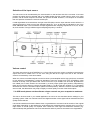
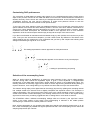
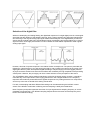
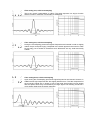
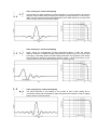
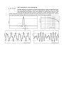
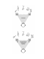
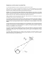
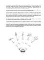
CORDA STAGEDAC
Digital-to-Analog Converter
with built-in
Crossfeed Filter
USER MANUAL
Dear music-lover,
The CORDA STAGEDAC is a high-end digital-to-analog converter (DAC). It has S/PDIF inputs as well as
an USB-input and thus can be directly connected to the digital output of your CD-player or to an USB-port
of your computer. In most cases this will strongly improve sound as the qualities of this DAC clearly
surpass those of the converter sections found in an average CD-player or on the soundcard of a
computer.
The STAGEDAC has one pair of output connections with a fixed output level that can be used to connect
to an (pre-)amplifier or a headphone amplifier. In addition it also has a pair of variable outputs to connect
and to drive a poweramplifier or a pair of active loudspeakers. Placed at the heart of your audiosystem, it
makes a simple-to-use control centre with excellent sound quality.
Using a pair of loudspeakers all sonic information is projected in the space between these two speakers.
The soundstage therefore has limited width. The STAGEDAC however, is able to electronically broaden
the soundstage beyond the limits of the loudspeakers. Especially with large-scale recordings this can
strongly improve our sense of space and live-feeling.
Due to the close contact to our ears, headphones provide an extreme channel separation whilst listening
to stereo recordings. Unlike loudspeakers, none of the sonic information in the left channel is acoustically
transferred to the right ear and vice versa. Although this adds to the extremely high level of detail that can
be achieved with headphones, it subconsciously also introduces mental stress. The natural correlation of
stereo sound interpreted by the brain is lost. The CORDA STAGEDAC not only offers normal stereo
reproduction of your music, but it also has a facility to add some of the left channel information to that of
the right channel and vice versa. Thus mental stress is reduced and music can be enjoyed with more
ease.
To obtain the best possible results with your new converter, we ask you to read these instructions
carefully. The STAGEDAC was developed by music-lovers for music-lovers and we hope that it will serve
you well for a long time.
Jan Meier
Power
The STAGEDAC can be connected to mains by a standard IEC powercord. The voltage range used,
100..(110)..120 Volts or 200..(220)..240 Volts, can be selected by the switch found on the bottom side.
!!! Always check the position of the voltage selector before connecting to mains !!!
On the rear side of the converter, as part of the power terminal, also a small compartment can be found
that contains a standard size slow T 200 mA fuse. If the device is connected to a mains voltage > 200
Volts with the voltage selector set to 110 Volts this fuse will blow and protect. The fuse can be easily
replaced but please always use one of the same value.
After connection the STAGEDAC can be switched on/off by the power switch at the left front-side. While
switched on, the LED-light at the middle of the frontplate will be lit.
The power consumption is approximately 7 Watts and the converter can be left on continuously if used
regularly. However, if the device is not used for a longer period of time it should be switched off.
Connections
On the rear side the STAGEDAC has two coaxial digital inputs, one optical TOSLINK digital input as well
as an USB-input.
If your CD-player or computer has a coaxial or optical digital output, then this output can be directly
connected to the STAGEDAC.
If your computer has no coaxial or optical output then you might choose to connect the CORDA
STAGEDAC to one of its USB-ports. With the power of the converter turned on, the computer will
automatically recognize its presence as an external USB-audio-DAC and configure it as its default audio
output device (provided no other USB-audio devices are connected simultaneously). You may have to
close and restart any running media application for them to recognize the device change. Users of the
music player foobar2000 need to change the output manually in the preferences section
(Playback/Output). Apple users may have to go to the computer control panel and actively select the
converter as their new sound device.
The converter has one pair of outputs with a fixed output level. This allows you to connect the converter
to a preamplifier, integrated amplifier, or headphone amplifier that has its own volume control.
The STAGEDAC also has a pair of variable outputs (preamp-out) that allow you to connect directly to a
power amplifier or to active loudspeakers. Volume can then be controlled on the converter.
Selection of the input source
The active source can be selected by the second switch on the left front side of the converter. In its lower
position the optical input is selected and in its middle position the first coaxial input is used. In its upper
position, with an active computer connected, the input will be USB. However, if no computer is connected
then this position will select the second coaxial input.
If valid digital data are received then the right most LED (kHz) near the input selection switch will be lit. A
sampling frequency close to one of the standard values 32, 44 or 48 kHz will be indicated by one of the
three additional LEDs. The STAGEDAC accepts digital data with sampling frequencies of 32, 44, 48, 88,
96, and 192 kHz. Through USB the highest sampling frequency is 48 kHz.
Volume control
The fixed output level of the STAGEDAC is 2.2 Vrms. When using the volume controlled connections the
output level can be varied from 0 to 2.2 Vrms using the dial on the right front side of the converter.
Volume is increased by clock-wise rotation.
When the volume controlled outputs are used to drive a poweramplifier with a high gain factor connected
to high efficiency loudspeakers, it might be desirable to lower the output level of the STAGEDAC. After
removal of the top cover just behind the volume control two 4-pin headers can be found. By default the
two middle pins of each header are connected by a shunt jumper (HIGH gain position). Repositioning
these shunt jumpers allows to reduce the output level by 13 dB (LOW gain position) or to completely
deactivate the volume controlled outputs (DEACTIVATED position). When the volume controlled outputs
are not used, the deactivation may help to slightly increase quality of sound of the fixed outputs.
!! In USB mode please set the software volume controls on your computer to maximum.
!!
This has to be done both in your media-application as well as in the soundcard device settings in your
operating system. With non-maximal volume the digital resolution of the signal will be lowered and sound
quality will be reduced.
It should be noted that windows-software does not guarantee an accurate bit-to-bit transfer of the original
audio-data. Depending on the settings the original data are resampled and/or resized which can have a
major effect on sound quality. For optimal sonic results the user might use alternative software (e.g.
ASIO-software) that guarantees a bit-to-bit data transfer and thus prevents unwanted sonic degradation.
Customising DAC-performance
The conversion of digital data into analog audio signals is not a straightforward process. During various
steps of this process, choices can be made that allow to tune the sonic results towards the sound that is
desired. Normally, these choices are made by the designer/manufacturer of the DAC-device. With the
STAGEDAC however, the user has the opportunity to make some personal choices to tune the
performance of the DAC-section towards his own personal taste.
To the right of the input selection switch two additional switches can be found that control the various
options offered. Each switch has three different positions. Thus the user has 9 different combinations to
choose from. More detailed technical descriptions are given in the sections below. However, please
understand that these descriptions are somewhat limited in their approach since a more extensive
explanation of all the various aspects would simply be beyond the scope of this user manual.
If you feel uncomfortable to read these technical details simply try each position and use the one you like
most. Trust your own ears and don’t despair if you find it hard to hear any difference. The effects of the
various settings are very subtle and it is our suggestion that you first try and compare the following three
settings while listening to signals at 44 or 48 kHz.
This setting represents the classic approach for DAC-performance
Technically this approach is the closest to a vinyl record player
A setting for optimal timing and pacing
Selection of the oversampling factor
When an analog signal is digitalized it is sliced into equal intervals of time, the so-called sampling
intervals. During each interval the digitalized signal is given a fixed amplitude. A straightforward
reproduction of the digital data would make a signal shape as shown in the middle figure below. The
resulting waveform is extremely rugged and to obtain a smooth signal strong additional analog filtering is
required. However, such analog filtering is very difficult to achieve without major sonic deterioration.
The situation during replay of the digital data can be strongly improved by splitting each sampling interval
into multiple smaller time intervals and to digitally interpolate the amplitude values. This technique is
called oversampling. The right picture below shows how each original sampling interval is split into 4
smaller time intervals: 4-fold oversampling. The resulting waveform is much closer to the original analog
signal and to remove any remaining ruggedness with an analog filter is much easier to achieve.
The STAGEDAC offers 3 different oversampling settings which are chosen by the right DAC controlswitch. In the upper position of this switch 2-fold oversampling is selected. In the middle position
oversampling is 4-fold and in the lowest position it is 8-fold.
Note: 8-fold oversampling is only possible with digital input signals with sampling frequencies up to 48
kHz. 4-fold oversampling is possible with signals upto 96 kHz and 2-fold oversampling can be used at all
sampling frequencies upto 192 kHz.
Selection of the digital filter
Without oversampling and analog filtering the digitalized response of a single digital pulse is a rectangular
signal that has the duration of the sampling interval. Such a signal contains very fast signal changes that
do not belong to the original analog input signal. Mathematical analysis of the digitalization process has
shown that each signal pulse has to be substituted (using oversampling and analog filtering) by a sin(x)/x
signal as shown in the right picture below in order to obtain the most faithful reproduction of the original
analog input signal
However, this kind of impulse response is not without further consequences. The pulse is preceded and
followed by a high-frequency pre- and post-ringing that by many people is thought to be the cause of the
digital glare that very often accompanies digital recordings. The post-ringing is not the biggest problem,
as psychoacoustic studies have shown that its effects are masked by the high amplitude of the preceding
central pulse. However, the pre-ringing can have a clear influence on the perception of the sound.
The STAGEDAC offers various settings that allow to minimize the signal ringing. However, it should be
noted that any such improvement of the ringing phenomenon has a negative effect on the frequency
response and introduces phase shifts at the highest frequencies. Any setting therefore is a compromise,
and it is up to the user to decide which setting sounds best.
For each oversampling rate three different filter settings can be selected using the left DAC-controlswitch. Each different combination of filtering and oversampling is briefly discussed below.
Note: Frequency and pulse responses are shown for input signals with a sampling frequency of 44 kHz
(standard CD-reproduction). For different sampling frequencies the time-axes and the frequency axes
have to be scaled accordingly
Filter setting one, 8-fold oversampling
This is the “classic” interpretation of a DAC. The pulse response is a sin(x)/x function
and the frequency response is (practically) a straight line.
Filter setting two, 8-fold oversampling
During the oversampling process the highest frequencies are lowered in order to slightly
reduce the pre- and post-ringing. Compared to the classic approach the sound is a little
bit less edgy, but it should be noted that sonic differences are very small and hardly
audible.
Filter setting three, 8-fold oversampling
Again, during the oversampling process the upper frequencies are lowered. However, in
addition these high frequencies are also slightly shifted in time. Thus the components of
the pre-ringing signal are no longer in front of the large signal pulse but now appear
after this pulse, where they are masked by its larger signal. The resulting sound has a
more analog quality than the classic approach.
Filter setting one, 4-fold oversampling
In this mode, the upper frequencies, and thereby the pre- and post-ringing, are strongly
lowered. Using 44 kHz data (CD-replay) the frequency range reaches to 14 kHz only (3dB). The pre- and post-ringing have decreased, but be noted that they now have lower
intrinsic frequencies and may still be audible.
Filter setting two, 4-fold oversampling
Again, during the oversampling process frequencies above 14 kHz are strongly
reduced. However, in addition the high frequencies are shifted in time as to remove any
pre-ringing. Technically spoken this filter setting resembles vinyl-playback most closely.
Vinyl records are limited to a frequency range of 14kHz .. 16 kHz and show no preringing because of the time shifts introduced by the analog filtering.
Filter setting three, 4-fold oversampling
The pulse response of this setting is very similar to that of filter setting two in
combination with 8-fold oversampling. Upper frequencies are lowered in order to slightly
reduce the pre- and post-ringing.
Filter setting one, 2-fold oversampling
In its shape the pulse response at this setting is a rounded approximation of the original
pulse without any major pre- and postringing. However, to obtain this result a price is
paid in the reproduction of signals that have frequencies above 14 kHz. The additional
figure shows the reproduction of both a 12 kHz and a 20 kHz sinus signal. Whereas the 12 kHz still has a
steady amplitude, the amplitude of the 20 kHz strongly wobbles. Moreover, frequency analysis of the
resulting signal shows that additional signal components are created beyond the theoretical upper limit of
22 kHz (aliasing). Because the adverse effects are found in the high-frequency band, appreciation of this
mode will strongly depend on personal hearing. Trying is the only way to know.
Filter setting two, 2-fold oversampling
This filter setting is very similar to that of the setting discussed above. The amplitude of
high frequency signals is not steady and additional signal components are created
above the limit of 22 kHz. The main difference is that the little pre-ringing that was left is
now removed by additional time delays in the high-frequency domain.
Filter setting three, 2-fold oversampling
This filter settings is very special in that the pulse response is much smaller/shorter than
it is in the other filter settings. It is a kind of response that is similar to that of so-called
non-oversampling DAC-devices. The pulse response is almost free of any pre- and
post-ringing but the price that is paid is a large one. Strong side-band effects create
strong components beyond the upper limit of 22 kHz as can be clearly shown in the response of a 12 kHz
sinus signal. As always appreciation of this mode will strongly depend on personal hearing.
Loudspeakers and the natural crossfeed filter
By nature the soundstage produced by loudspeakers in a stereo-setup is limited to the space between
these speakers. Reflections of the sound waves from the walls as well as reverberation may create an
enhanced feeling of spaciness, but the position of a source of sound will always be projected within the
boundaries of the speakers.
With music that requires a wide sounstage (large orchestral or choral music for instance) the limitations
given by the speaker-setup often result that the most outwards instruments or singers are not projected
“full-body” but in a relatively small space in the direction of the corresponding speaker. This can strongly
hamper live-feeling, especially when the loudspeakers are placed relatively close to each other.
The sound of a source to the right side of the listener not only reaches the right ear but, attenuated and
delayed, is also heard by the left ear. However, since it has to travel a longer way to reach the left ear it
will be slightly delayed in time. And because of the shadowing effect of the head it will also be smaller in
amplitude. The level of attenuation and the delay time of this crossfeed signal provide important
directional information. Within a speaker setup the amount of signal that reaches the opposite ear is
always relatively large and the delay time is relatively short. This prevents the brain from “detecting” wider
angles.
The CORDA STAGEDAC can electronically enhance the soundstage. It has a so-called crossfeed filter
that can be activated by the second switch from the right side of the front plate (crossfeed mode). The
switch has three positions. In its middle position no crossfeed is present and sound reproduction is
standard stereo. In its lower position the filter will work in speaker-mode. In its upper position it will be in
headphone-mode (to be discussed later).
With the crossfeed filter set to loudspeaker-mode the signal of the right stereo channel will be slightly
delayed and attenuated and next subtracted from the signal offered to the left loudspeaker. This delayed
signal will reach the left ear at the same time as the original right channel signal that comes from the right
loudspeaker and, as it has opposite phase, it will partly cancel this original signal. Thus the amplitude of
the right channel signal that reaches the left ear is effectively lowered. The brain interpretes this as an
increase of the angle by which the sound is to be projected into the soundstage.
The same process is also performed for the left channel signal. Thus the total soundstage is widened
beyond the limits of the speakers. Instruments normally projected in the direction of the loudspeakers get
more body and live-feeling is enhanced.
The third switch from the front right side of the STAGEDAC controls the amplitude of the crossfeed signal
(crossfeed intensity). It is highest in the upper position. The optimal choice for the crossfeed intensity
level is a matter of personal taste and may well depend on the loudspeakers, the choice of music, and the
listening envirenmont.
The optimal delay time is not an universal value but is determined by the angle by which the
loudspeakers are seen from the listening position as well as by the size and shape of the head of the
listener. It can be controlled by the fourth switch from the right (crossfeed delay). In its upper position the
delay time interval is relatively long. In its lower position is is short. As a rule of thumb for angles of
around 30..40 degrees (standard stereo-setup) the delay should be set to high. For smaller angles one
may experiment with shorter delay times.
The optimal delay time is critical for the tonal color by which we hear the instruments that are placed at
the boundaries of the soundstage. If it is not set properly then certain frequency components will be
slightly reduced or accentuated (due to the so-called comb effect). In order to find the best personal
settings we advise to connect the STAGEDAC to a computer by USB and listen to a mono-recording.
Inside the Media-Player set the balance to one channel only. Direct your face to the middle of the
loudspeakers. With speaker crossfeed activated the tonal quality will slightly vary with the delay time.
When the delay time is set properly the tone will be rich and full-bodied over the entire frequency
spectrum.
If you feel uncomfortable in “calibrating” the crossfeed simply use the high delay value when you use a
standard loudspeaker setup. Use the medium delay value when the loudspeakers are relatively close.
The effect and thereby the benefits of loudspeaker crossfeed is mostly present with recordings that have
a wide soundstage. Its effect is subtle but can be very helpfull. With small scale “narrow” recordings the
effect will be far more difficult to be noticed.
It should be noted that the crossfeed circuitry of the CORDA STAGEDAC “recognizes” the virtual
positions of the instruments and singers in a recording. The sound of an instrument in the middle of the
soundstage will be equally present in both audio-channels and isn’t given any crossfeed. A crossfeed
signal is only generated for instruments that are not placed at the center. The more off-center the
instrument is placed, the stronger the crossfeed. This guarantees that the filter has no influence on the
sound of more central instruments or singers.
Headphones and the natural crossfeed filter
In normal daily life people use various mechanisms to locate sources of sound.
Firstly, the sound of a source to the right side of the listener (e.g. the right loudspeaker) not only reaches
the right ear, but, attenuated and delayed, is also heard by the left ear. The level of attenuation and the
delay time of this crossfeed signal provide important directional information.
Secondly, the sound waves are partly absorbed and partly reflected by the tissues of the head.
Reflections at the oracles (pinnae) interfere with the sound waves that directly enter the ear-channel and
amplify or attenuate specific frequency components. Since these reflections depend on the direction of
the sound wave, the “color” of the sound changes with the direction of the source.
Thirdly, reflections of the sound waves from the walls, ceiling and floor of our listening room produce
reverberation that conveys an extra feeling of space.
The information obtained by these mechanisms is further refined by movements of the head. Changes in
sound levels, delay times and sound color refine the sense of direction. For a demonstration, blindfold a
friend and ask him to locate a ticking clock that you have hidden in the room. He will start turning his head
although he can’t see anything. With his head in a fixed position, an exact localization is much more
difficult.
All these mechanisms are missing when we listen to music by headphones. The sound at the right ear will
no longer reach the left ear, and pinnae-reflections no longer interfere with the original soundwave.
Moreover, the headphones are directly attached to our head, and so head movements no longer add
information. Reverberation is also not present.
As a result, the sound heard by headphones seems to stick to the inside of our head and an unnatural
soundfield is created. The brain misses logical clues for direction, and this subconsciously results in
mental stress. Some people cannot tolerate this stress and are unable to use headphones for longer
periods of time.
In principle, digital soundprocessors can simulate all the mechanisms for directional listening, but the
results are, thus far, not very satisfactory. In particular, pinnae-reflections are very complex and listenerspecific and impossible to simulate accurately.
Fortunately the main directional information is provided by the time delay and level of attenuation of the
sounds that reaches the opposite ear and the crossfeed filter of the CORDA STAGEDAC can
electronically simulate this process. In headphone mode the signals of each of the two stereo channels
will be slightly delayed, attenuated and next added to the signal of the opposite channel. This
considerably reduces the adverse symptoms of headphone listening.
The optimal choices for the delay times as well as the attenuation levels are depending on many factors
such as the headphone, personal preferences and the specific recording listened to.
In order to find the best personal settings we advise to connect the STAGEDAC to a computer by USB.
Next listen to music while inside the Media-Player the balance is set to one channel only. With music
present on one side only the effects of delay time and crossfeed intensity will become very obvious. It is
then upto the user to decide which combinations of settings suits him best. In this there is no right or
wrong. Always trust your own ears! If you feel uncomfortable in “calibrating” the crossfeed simply use the
average settings for both delay and intensity. They will work fine for most of the time.
The effect and thereby the benefits of headphone crossfeed strongly depend on the recording.
Sometimes the effect is very subtle, but especially with elder records, which often have a very strong leftrigh separation of the individual instruments, the effect can be very noticable.
A unique feature of the crossfeed circuitry of the CORDA STAGEDAC is that it “recognizes” the virtual
positions of the instruments and singers in a recording. The sound of an instrument in the middle of the
soundstage will be equally present in both audio-channels and isn’t given any crossfeed. A crossfeed
signal is only generated for instruments that are not placed at the center. The more off-center the
instrument is placed, the stronger the crossfeed and the longer its delay. This feature is called “natural
crossfeed” and results in a more precise imaging than can be achieved with more conventional crossfeed
filters that even produce crossfeed with mono-signals.
Tonal balance
Psychoacoustic studies have shown that our sense of direction is mainly determined by the sonic
components with frequencies upto 2 kHz. To keep the sonic signals as much as possible in their originial
state the crossfeed filter does not effect signal components above this frequency.
In headphone mode signals that are no longer present in one channel only but are now more evenly
distributed over both channels will be less isolated and become a more integrated part of the soundstage.
They no longer stand out and this may feel as if the energy in the frequency range below 2 kHz is slightly
reduced. This can be compensated by the first switch to the front right side of the STAGEDAC. In its
lower position no frequency corrections are made but in its middle and in its upper position frequencies
below 2 kHz are slightly elevated to correct the tonal balance.
Technical data
Measures:
28.0 x 17.5 x 6.7 cm
Weight:
1.9 kg.
Power supply:
100..120V / 200..240 Volts mains. Voltage range is selectable.
Power uptake:
7 Watts
Output voltage:
2.2 Vrms (fixed outputs)
0 .. 2.2 Vrms (volume controlled outputs, high output level)
0 .. 0.5 Vrms (volume controlled outputs, low output level)
Output impedance:
47 Ohm (fixed outputs)
0 .. 260 Ohm (volume controlled outputs, high output level)
0 .. 1.1 kOhm (volume controlled outputs, low output level)
Digital resolution USB
16 bit
Sampling frequencies USB
32 / 44 / 48 kHz
Digital resolution S/PDIF
16 / 20 / 24 bit
Sampling frequencies S/PDIF
32 / 44 / 48 / 88 / 96 / 192 kHz


![VTW Software Operation manual[PDF:17.4MB] - FOR](http://vs1.manualzilla.com/store/data/005725901_1-df2c6d7f9199f46fcf33ffa12e63545b-150x150.png)