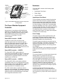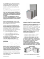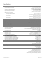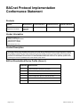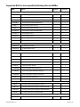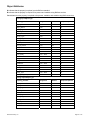
1
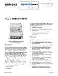
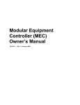
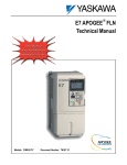
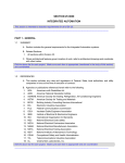
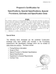
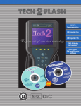
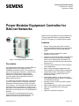
Technical Specification Sheet Document No. 149-203 December 2, 2009 Power Modular Equipment Controller for BACnet Networks Based on the Power MEC part number selected, the FLN may support RS-485 for configurable BACnet MS/TP or P1 support or LonTalk® protocol support. Features BACnet Testing Laboratories (BTL) certified Classified as BACnet Building Controllers (B-BC) using the BACnet/IP protocol and/or BACnet MS/TP. Several versions of controllers to match application requirements. Remote-mounted external analog and digital point expansion modules for added point expansion, which may be independently operated as FLN devices or directly controlled on an optional point expansion bus. Proven program sequences to match equipment control applications. Built-in energy management applications and DDC programs for complete facility management. Comprehensive alarm management, historical data trend collection, operator control and monitoring functions. Sophisticated Adaptive Control, a closed loop control algorithm that auto-adjusts to compensate for load/seasonal changes. Message control for terminals, printers, pagers and workstations. Figure 1. Power Modular Equipment Controller. Description The Power Modular Equipment Controller (MEC) for BACnet® Networks is an integral part of the APOGEE® Automation System. The controller is a part of a family of high performance, modular Direct Digital Control (DDC) supervisory equipment controllers. It is classified as a BACnet Building Controller (B-BC) and supports BACnet/IP and BACnet MS/TP protocols. The Power MEC operates stand-alone or networked to perform complex control, monitoring and energy management functions without relying on a higherlevel processor. The Power MEC communicates with other field panels or workstations on a peer-to-peer Automation Level Network (ALN) and supports native BACnet/IP communications over 10/100 MB Ethernet networks. The Power MEC can optionally provide central monitoring and control for distributed Field Level Network (FLN) devices (wired or wireless). Siemens Industry, Inc. Optional Hand Off Auto (HOA) control switches. Option for compatibility with LONWORKS® networks. Optional P1 Wireless FLN support. Page 1 of 19 DIGITAL INPUT CONNECTORS DI2 43 DI3 65 HOA LED DI4 87 9 10 DI5 11 12 DI6 13 14 DI7 15 DI8 16 A ANALOG OUTPUT CONNECTORS A 25 + 17 + AO13 26 AO9 18 27 A+ 19 + AO14 28 AO10 20 29 + 21 + AO15 30 AAO11 22 31 + AO16 32 23 + AO12 24 - 24 VDC SENSOR POWER SHIELD TERMINATION A A HOA CONTROL SWITCHES 0A DIGITAL OUTPUT CONNECTORS 24 VAC POWER CONNECTOR 53 + 24 VDC 54 55 SENSOR 56 SUPPLY 49 50 51 52 SHIELD AI21 4241-+ 33 + 34 AI22 4443-+ AI18 3635-+ AI23 4645-+ AI19 3837-+ 47 + AI24 48 AI20 4039-+ FLN FLN FLN BLN 5 4 3 2 1 FLN CONNECTORS (3) TX RX EXP RX TX Hardware The Power MEC consists of the following major components: Input/Output Point Board Power Supply Controller Board ENET MO DE M STAT US BATT LNK/ AC T 100 TX FULL /COL RX RX TX RX TX TX RX RX AI17 RS 422 ANALOG INPUT CONNECTORS C 57 DO25 NO 58 NC 59 C 60 DO26 NO 61 NC 62 0A C 63 DO27 NO 64 NC 65 0A C 66 A DO28 NO 67 NC 68 0A C 69 A DO29 NO 70 NC 71 0A C 72 DO30 NO 73 0A NC 74 C 75 DO31 NO 76 0 NC 77 A C 78 DO32 NO 79 NC 80 0 DI1 21 EXPANSION BUS CONNECTOR (EXP) ETHERNET PORT MEC0103R1 MMI PORT STATUS LEDS BATTERY COVER Figure 2. Power Modular Equipment Controller components and key features. The Power Modular Equipment Controller Several styles of controllers provide flexibility and expansion to meet application needs. All the Power MEC models for BACnet Networks support industry standard BACnet/IP networks through a direct connection to 10/100 Base-T for ALN communications. Power MEC Controller– 1200EB In addition to control of the 32 points on the input/output point board, this controller supports analog and digital point expansion modules, which can be mounted remote from the controller. This capability expands the point capacity of the Power MEC and provides for cost-effective placement of the point terminations close to the load. Power MEC Controller – 1200EFB The Power MEC “EFB” version adds three connections to the APOGEE P1 FLN, for a total of 96 devices supervised by the Power MEC, or it may be configured for a single BACnet MS/TP connection supporting up to 96 devices. Power MEC Controller – 1200ELB Input/Output Point Board The input/output point board contains 32 points that perform A/D or D/A conversion, signal processing, point command output and communication with the controller board. The terminal blocks are removable for easy termination of field wiring. The analog input points are selectable to be 0-10V, 4-20 mA, 1K RTD or optional 100K Thermistor. The analog output points are also selectable to be either 0-10V or 4-20 mA. The digital inputs are dry contact, with four being pulse accumulator inputs. The digital outputs support 110/220V Form C rated relays. Power Supply The power supply provides regulated power to the input/output point board and active sensors. The power supply is internal to the Power MEC housing, simplifying installation and troubleshooting. The power supply works with the controller board to ensure smooth power up and down sequences for the equipment controlled by the I/O point board and analog and digital point blocks, even through brownout conditions. Status LEDs indicate 24 Vac supplied from the power supply and 24 Vdc supplied to the input/output point board. Controller Board The controller board is a microprocessor-based multitasking platform for program execution and communications with the I/O point board and with other Power MECs and field panels over the ALN. The Power MEC “ELB” version adds LONWORKS compatibility at the FLN. It is equipped with a Neuron Microprocessor and FTT-10A Transceiver. Instead of three connections to the APOGEE FLN, it has a single connection for a LONWORKS network. The Power MEC can also support analog or digital point expansion modules, which provide for point expansion capability to match the application requirements. The controller board scans field data, optimizes control parameters and manages operator requests for data. The “ELB” versions have a LONWORKS network database server embedded. This database maintains a dynamic, real-time representation of the LONWORKS network including connections/bindings, node status, and configuration parameters values. An RS-232 operator terminal port with a quick connect phone jack (RJ-11) is included with each controller board for operator devices such as a Local User Interface (LUI), simple CRT terminal, laptop PC, or printer. Page 2 of 19 Siemens Industry, Inc. The 1200EFB controllers support 3 FLN trunks for communications with a total of 96 FLN devices, or one BACnet MS/TP trunk supporting up to 96 devices. The 1200ELB controllers support 1 FLN trunk for communications with a maximum of 126 LONWORKS devices. The program and database information stored in the Power MEC RAM memory is battery-backed. This eliminates the need for time-consuming program and database re-entry in the event of an extended power failure. When battery replacement is necessary, the controller board illuminates a “battery low” status LED and can send an alarm message to selected printers or terminals. The firmware, including the operating system, is stored in non-volatile flash ROM memory. Flash ROM is easily upgradeable at the job site. This provides for ease of upgrade as new firmware updates are made available. Brownout protection and power recovery circuitry protect the controller board from power fluctuations. PX Series Enclosure Assemblies PX series enclosures house both electronic and pneumatic components. The enclosures include a perforated backplane for mounting of the PXC series controllers, Power Modular Equipment Controllers, Point Expansion Modules or other electronic or pneumatic components. Two sizes are available (19” and 34”) that can house the Power MEC: 19” enclosure, hinged door and key lock 34” enclosure, hinged door and key lock 18" enclosure, pull-box type utility cabinet (for accessories, not for MEC) The enclosures are constructed of metal to accommodate secure conduit fittings and protect components against electrical transients. The enclosure allows space for easy wire routing and terminations. Service Box Service boxes are available for mounting in the 19” or 34” enclosures. Models provide step down power from either 115 Vac or 230 Vac to 24 Vac and offer protection against electrical transients. The service boxes are sized in various power ratings to provide one or two Class 1 Power Limited terminations for use inside the enclosure to power controllers and I/O modules, and one Class 2 termination for use outside the enclosure to power remote devices. The 115 Vac versions provide two 115 Vac outlets for accessory devices such as modems and laptops. Optional sidewall kits are available for service box installation in other NEMA Type 1 or better enclosures such as motor control cabinets. Siemens Industry, Inc. Figure 3. PX Series Enclosure Assemblies. Analog and Digital Point Expansion Modules In addition to the points on the input/output board, the Power MECs support analog and digital Point Expansion Modules. The controller can support a maximum of any combination of eight modules. They can be mounted next to or remote from the controller depending upon the job requirements. The total length of the wiring run for Point Expansion Modules is a maximum of 200 feet (61 meters) on the MEC expansion bus. Point Expansion Modules are also compatible with the APOGEE P1 FLN. Point Expansion Module details are: Analog Point Expansion Module – 4AI, 4AO Analog Point Expansion Module – 8AI Digital Point Expansion Module – 4DI, 4DO Digital Point Expansion Module – 8DI, 4DO The analog input points are user selectable to be 010V, 4-20 mA, 1K RTD or optional 100K Thermistor input. The analog output points are also user configurable to be 0-10V or 0-20 mA. The digital inputs are dry contact with four of the inputs being pulse accumulator points. The relayed digital output points support 110/220V Form C relays. Figure 4. Analog and Digital Point Expansion Modules. Page 3 of 19 Modular Equipment Control with Application Flexibility Built-in Direct Digital Control Routines The Power MECs are high performance controllers with complete flexibility to allow the owner to customize each controller with the exact program for the application. In addition, each controller can be sized to meet the hardware requirements for the application. The Power MEC provides stand-alone Direct Digital Control (DDC) to deliver precise HVAC control and comprehensive information about system operation. The controller receives information from sensors in the building, processes the information, and directly controls the equipment. The following functions are available: The control program for each Power MEC is customized to exactly match the application. Proven Powers Process Control Language (PPCL), a BASIC type programming language provides direct digital control and energy management sequences to control equipment precisely and optimize energy usage. Global Information Access Each Power MEC is equipped with one RS-232 operator terminal port. This port supports the connection of a Local User Interface (LUI), simple CRT terminal, laptop PC, or printer. Devices connected to the terminal port gain global information access. Multiple Operator Access Multiple operators can access the network simultaneously. Multiple operator access ensures that alarms are reported to an alarm printer while an operator accesses information from a local terminal. When using the BACnet/IP ALN option, multiple operators may also access the controller through concurrent Telnet sessions and/or local operator terminal ports. Menu Prompted, English Language Operator Interface The Power MEC has a simple, yet powerful menu driven English Language Operator Interface that provides, among other things: Point monitoring and display Point commanding Historical trend collection and display for multiple points Event scheduling Program editing and modification via Powers Process Control Language (PPCL) Alarm reporting and acknowledgment Continual display of dynamic information Page 4 of 19 Adaptive Control, an auto-adjusting closed loop control algorithm, which provides more efficient, adaptive, robust, fast, and stable control than the traditional PID control algorithm. It is superior in terms of response time and holding steady state, and at minimizing error, oscillations, and actuator repositioning. Closed Loop Proportional, Integral and Derivative (PID) control. Logical sequencing. Alarm detection and reporting. Reset schedules. Built-in Energy Management Applications The following applications are programmed in the Power MEC and require simple parameter input for implementation: Automatic Daylight Saving Time switchover Calendar-based scheduling Duty cycling Economizer control Equipment scheduling, optimization and sequencing Event scheduling Holiday scheduling Night setback control Peak Demand Limiting (PDL) Start-Stop Time Optimization (SSTO) Temperature-compensated duty cycling Temporary schedule override Siemens Industry, Inc. Specifications Dimensions: Modular Equipment Controller Analog Point Expansion Module Digital Point Expansion Module 11.4" H × 9.5" W × 3.75" D (289 mm × 241 mm × 95 mm) 6" H × 9.5" W × 3.75" D (152 mm × 241 mm × 95mm) 6" H × 9.5" W × 3.75" D (152 mm × 241mm × 95mm) NEMA Type 1 Enclosures: 18” Utility Cabinet Enclosure 19” Enclosure 34” Enclosure Processor Motorola MPC - 1200EB, 1200EFB, 1200ELB Processor Clock Speed Memory Size Battery Backup of RAM A/D Resolution (analog in) D/A Resolution (analog out) Local Communication Interface Network Communication Speed Automation Level Network Field Level Network Point Expansion Bus Voltage Requirements Service Box, 115V Service Box, 230V Controller or Expansion Module Power Consumption Power Modular Equipment Controllers Analog Point Expansion module 8AI Analog Point Expansion module 4AI/4AO Digital Point Expansion module 8DI/4DO Digital Point Expansion module 4DI/4DO Enclosure Type Ambient Operating Environment Mounting Surface Agency Listings Agency Compliance 18" H × 14" W × 6" D (457.2 mm × 356.6 mm × 152.4 mm) 19" H × 22" W × 5.75" D (482.6 mm × 558.8 mm × 146.1 mm) 34" H × 22" W × 5.75" D (863.6 mm × 558.8 mm × 146.1 mm) 860T 48 MHz 64 MB RAM/8 MB Flash (72 MB Total) 14 days typical (field replaceable, AA Alkaline) 12 bits 8 bits RS-232 port BACnet/IP ALN: 10/100 Base-T P1 FLN or BACnet MS/TP FLN: 9600, 19200, 38400 LONWORKS FLN: 38.4 Kbps 38.4 Kbps 115 Vac +/- 15% @ 60 Hz +/- 5% 230 Vac +/- 15% @ 50/60 Hz +/- 5% 20 Vac to 30 Vac @ 47 Hz to 63 Hz 50 VA 17 VA @ 24 Vac 14 VA @ 24 Vac 20 VA @ 24 Vac 17 VA @ 24 Vac NEMA 1 +32F to +120F (0C to +49C) 93% RH (Non-condensing) Building Wall or Structural Member UL 864 UUKL ULC-C100 UUKL7 UL 916 PAZX FCC Compliance Australian EMC Framework European EMC Directive (CE) European Low Voltage Directive (LVD) BACnet Testing Laboratories (BTL) Certified Siemens Industry, Inc. Page 5 of 19 Ordering Information Controller Range Description Product Number Power MEC 1200EB, 8DI, 8DO, 8AI, 8AO, point expansion support, HOAready, BACnet/IP ALN 549-632 Power MEC 1200EFB, 8DI, 8DO, 8AI, 8AO, point expansion support, FLN support, HOA-ready, BACnet/IP ALN 549-634 Power MEC 1200ELB, 8DI, 8DO, 8AI, 8AO, point expansion support, LONWORKS network, HOA-ready, BACnet/IP ALN 549-636 Point Expansion Modules Description Product Number Analog Point Expansion Module, 4AI/4AO 24V HOA-ready – for MEC Expansion or FLN 549-214 Analog Point Expansion Module, 4AI/4AO 24V with HOA – for MEC Expansion or FLN 549-215 Digital Point Expansion Module, 4DI/4DO 24V HOA-ready – for MEC Expansion or FLN 549-212 Digital Point Expansion Module, 4DI/4DO 24V with HOA – for MEC Expansion or FLN 549-213 Analog Point Expansion Module, 8AI 24V – for MEC Expansion or FLN 549-209 Digital Point Expansion Module, 8DI/4DO 24V HOA-ready – for MEC Expansion or FLN 549-210 Digital Point Expansion Module, 8DI/4DO 24V with HOA – for MEC Expansion or FLN 549-211 Accessories Description Product Number HOA Upgrade Kit Analog Point Block 4AI/4AO 549-520 HOA Upgrade Kit Digital Point Block 4DI/4DO 549-518 HOA Upgrade Kit Digital Point Block 8DI/4DO 549-519 MMI Extension Cable, (RJ-11 male to female) for printers or terminals outside of enclosure 545-712 MMI Cable (DB9 female to RJ-11 6-pin) for no flow control operator interface connections 540-143 Page 6 of 19 Siemens Industry, Inc. Service Boxes and Enclosures Description Product Number PX Series Service Box— 115V, 24 Vac, 50/60 Hz, 192 VA PXA-SB115V192VA PX Series Service Box— 115V, 24 Vac, 50/60 Hz, 384 VA PXA-SB115V384VA PX Series Service Box— 230V, 24 Vac, 50/60 Hz, 192 VA PXA-SB230V192VA PX Series Service Box— 230V, 24 Vac, 50/60 Hz, 384 VA PXA-SB230V384VA 18" Enclosure (Utility Cabinet) (UL Listed NEMA Type 1 Enclosure) PXA-ENC18 19” Enclosure (UL Listed NEMA Type 1 Enclosure) PXA-ENC19 34” Enclosure (UL Listed NEMA Type 1 Enclosure) PXA-ENC34 Documentation Description Document Number Power Modular Equipment Controller Owner’s Manual 125-2183 Powers Process Control Language (PPCL) User’s Manual 125-1896 Information in this document is based on specifications believed correct at the time of publication. The right is reserved to make changes as design improvements are introduced. APOGEE and Insight are registered trademarks of Siemens Industry, Inc. Other product or company names mentioned herein may be the trademarks of their respective owners. © 2009 Siemens Industry, Inc. Document No. 149-203 Siemens Industry, Inc. Your feedback is important to us. If you have Building Technologies Division comments about this document, please send them to Printed in U.S.A. [email protected]. 1000 Deerfield Parkway Page 7 of 19 Buffalo Grove, IL 60089-4513 U.S.A. BACnet Protocol Implementation Conformance Statement Products Product Model Number Power BACnet Modular Equipment Controller 1200-EFB 1200-ELB 1200-EB Protocol Revision Software Revision 135-2004 N/A Firmware Revision 3.2 Vendor Information Siemens Industry, Inc. Building Technologies Division 1000 Deerfield Parkway Buffalo Grove, IL 60089 www.sbt.siemens.com Product Description An integral member of the APOGEE product family, the Power MEC for BACnet Networks is a high performance, modular Direct Digital Control (DDC) supervisory equipment and primary building controller. The Power MEC operates stand-alone or networked to perform complex control, monitoring and energy management functions without relying on a higher-level processor. The Power MEC communicates on a 10/100 MB Ethernet BACnet/IP network. It can optionally provide central monitoring and control for distributed Field Level Network (FLN) devices. BACnet Standardized Device Profile (Annex L) Supported Device Profile BACnet Operator Workstation (B-OWS) BACnet Building Controller (B-BC) BACnet Advanced Application Controller (B-AAC) BACnet Application Specific Controller (B-ASC) BACnet Smart Actuator (B-SA) BACnet Smart Sensor (B-SS) Page 8 of 19 Siemens Industry, Inc. Supported BACnet Interoperability Building Blocks (BIBBs) BIBB Name Initiate Execute Data Sharing DS-RP-A Data Sharing-ReadProperty-A DS-RP-B Data Sharing-ReadProperty-B DS-RPM-A Data Sharing-ReadPropertyMultiple-A DS-RPM-B Data Sharing-ReadPropertyMultiple-B DS-WP-A Data Sharing-WriteProperty-A DS-WP-B Data Sharing-WriteProperty-B DS-WPM-B Data Sharing-WritePropertyMultiple-B DS-COV-A Data Sharing-COV-A DS-COV-B Data Sharing-COV-B DS-COVU-A Data Sharing-COV-Unsolicited-A DS-COVU-B Data Sharing-COV-Unsolicited-B SCHED-I-B Scheduling-Internal-B SCHED-E-B Scheduling-External-B Scheduling Alarm and Event Management AE-N-A Alarm and Event-Notification-A AE-N-I-B Alarm and Event-Notification Internal-B AE-N-E-B Alarm and Event-Notification External-B AE-ACK-A Alarm and Event-ACK-A AE-ACK-B Alarm and Event- ACK-B AE-ASUM-B Alarm and Event-Alarm Summary-B AE-ESUM-A Alarm and Event-Enrollment Summary-A AE-ESUM-B Alarm and Event-Enrollment Summary-B AE-INFO-A Alarm and Event-Information-A AE-INFO-B Alarm and Event-Information-B Trending T-VMT-A Trending-Viewing and Modifying Trends-A T-VMT-I-B Trending-Viewing and Modifying Trends-Internal-B T-VMT-E-B Trending-Viewing and Modifying Trends-External-B T-ATR-B Trending-Automated Trend Retrieval-B Network Management NM-CE-A Siemens Industry, Inc. Network Management-Connection Establishment-A Page 9 of 19 BIBB Name Initiate Execute Device Management DM-DDB-A Device Management-Dynamic Device Binding-A DM-DDB-B Device Management-Dynamic Device Binding-B DM-DOB-A Device Management-Dynamic Object Binding-A DM-DOB-B Device Management-Dynamic Object Binding-B DM-DCC-B Device Management-DeviceCommunicationControl-B DM-PT-A Device Management-Private Transfer-A DM-PT-B Device Management-Private Transfer-B DM-TM-A Device Management-Text Message-A DM-TM-B Device Management-Text Message-B DM-TS-B Device Management-TimeSynchronization-B DM-RD-B Device Management-ReinitializeDevice-B DM-BR-B Device Management-Backup and Restore-B DM-LM-B Device Management-List Manipulation-B DM-OCD-B Device Management-Object Creation and Deletion-B Standard Object Types Supported Name Creatable Deletable Analog Input Analog Output Analog Value Binary Input Binary Output Binary Value Calendar Command Notification Class Schedule Device Event Enrollment File Multi-state Output Multi-state Value Trend Log Page 10 of 19 Siemens Industry, Inc. Object Attributes O indicates that the property is optional, per the BACnet standard. R indicates that the property is required to be present and readable using BACnet services. Yes indicates that the property is required to be present, readable, and writable using BACnet services. Analog Input Object Type Property_Identifier Supported Writable Required \ Optional Object_Identifier Yes R Object_Name Yes R Object_Type Yes Present_Value Yes Yes R Description Yes Yes O Device_Type Yes O Status_Flags Yes R Event_State Yes R Reliability Yes O Out_Of_Service Yes Yes R Units Yes Yes R Resolution Yes COV_Increment Yes Time_Delay Yes - Alarm Notification Class Yes - Alarm Yes O High_Limit Yes - Alarm Yes O Low_Limit Yes - Alarm Yes O Deadband Yes - Alarm O Limit_Enable Yes - Alarm O Event_Enable Yes - Alarm Acked_Transitions Yes - Alarm O Notify_Type Yes - Alarm O Event_Time_Stamps Yes - Alarm O R O Yes O O Yes O Analog Output Object Type Property_Identifier Supported Writable Required \ Optional Object_Identifier Yes Object_Name Yes R Object_Type Yes R Present_Value Yes Yes Description Yes Yes Device_Type Yes O Status_Flags Yes R Event_State Yes R R W O Reliability Yes O Out_Of_Service Yes R Units Yes R Siemens Industry, Inc. Page 11 of 19 Min_Pres_Value No O Max_Pres_Value No O Resolution Yes O Priority_Array Yes R Relinquish_default Yes R COV_Increment Yes Yes O Time_Delay Yes - Alarm Notification Class Yes - Alarm Yes O O High_Limit Yes - Alarm Yes O Low_Limit Yes - Alarm Yes O Deadband Yes - Alarm O Limit_Enable Yes - Alarm O Event_Enable Yes - Alarm Acked_Transitions Yes - Alarm O Notify_Type Yes - Alarm O Event_Time_Stamps Yes - Alarm O Yes O Analog Value Object Type Page 12 of 19 Property_Identifier Supported Writable Required \ Optional Object_Identifier Yes R Object_Name Yes R Object_Type Yes Present_Value Yes Yes R Description Yes Yes O R Status_Flags Yes R Event_State Yes R Reliability Yes O Out_Of_Service Yes R Units Yes R Priority_Array Yes O Relinquish_default Yes O COV_Increment Yes Time_Delay Yes - Alarm Notification Class Yes - Alarm Yes O High_Limit Yes - Alarm Yes O Low_Limit Yes - Alarm Yes O Deadband Yes - Alarm O Limit_Enable Yes - Alarm O Event_Enable Yes - Alarm Acked_Transitions Yes - Alarm O Notify_Type Yes - Alarm O Event_Time_Stamps Yes - Alarm O Yes O O Yes O Siemens Industry, Inc. Binary Input Object Type Property_Identifier Supported Object_Identifier Yes Object_Name Yes R Object_Type Yes R Present_Value Yes Yes Description Yes Yes Device_Type Yes O Status_Flags Yes R Event_State Yes R Reliability Yes Out_Of_Service Yes Polarity Yes Writable Required \ Optional R R O O Yes R R Inactive_Text Yes O Active_Text Yes O Elapsed_Active_Time Yes Time_Of_Active_Time_Reset Yes Time_Delay Yes - Alarm Notification Class Yes - Alarm Alarm_Value Yes - Alarm Yes O O O Yes O O Event_Enable Yes - Alarm Acked_Transitions Yes - Alarm Yes O O Notify_Type Yes - Alarm O Event_Time_Stamps Yes - Alarm O Binary Output Object Type Property_Identifier Supported Writable Required \ Optional Object_Identifier Yes Object_Name Yes R Object_Type Yes R Present_Value Yes Yes W Description Yes Yes O Device_Type Yes O Status_Flags Yes R Event_State Yes R R Reliability Yes O Out_Of_Service Yes R Polarity Yes R Inactive_Text Yes O Active_Text Yes Elapsed_Active_Time Yes Time_Of_Active_Time_Reset Yes O Priority_Array Yes R Relinquish_default Yes R Siemens Industry, Inc. O Yes O Page 13 of 19 Time_Delay Yes - Alarm Notification Class Yes - Alarm O Yes O Yes O Feedback_Value Yes - Alarm Event_Enable Yes - Alarm O Acked_Transitions Yes - Alarm O Notify_Type Yes - Alarm O Event_Time_Stamps Yes - Alarm O Binary Value Object Type Property_Identifier Supported Writable Required \ Optional Object_Identifier Yes R Object_Name Yes R Object_Type Yes R Present_Value Yes Yes Description Yes Yes Status_Flags Yes R Event_State Yes R R O Reliability Yes O Out_Of_Service Yes R Inactive_Text Yes O Active_Text Yes O Elapsed_Active_Time Yes Time_Of_Active_Time_Reset Yes Yes O Priority_Array Yes O Relinquish_default Yes O Time_Delay Yes - Alarm O Notification Class Yes - Alarm Alarm_Value Yes - Alarm Yes O O O Event_Enable Yes - Alarm Acked_Transitions Yes - Alarm Yes O O Notify_Type Yes - Alarm O Event_Time_Stamps Yes - Alarm O Calendar Object Type Page 14 of 19 Property_Identifier Supported Writable Required \ Optional Object_Identifier Yes Object_Name Yes R Object_Type Yes R Description Yes Present_Value Yes Date_List Yes R Yes O R Yes R Siemens Industry, Inc. Command Object Type Property_Identifier Supported Writable Required \ Optional Object_Identifier Yes Object_Name Yes R Object_Type Yes R Description Yes Yes O Present_Value Yes Yes W In_Process Yes R All_Writes_Successful Yes R Action Yes Yes R Action _Text Yes Yes O Property_Identifier Supported Writable Required \ Optional Object_Identifier Yes R Object_Name Yes R Object_Type Yes R System_Status Yes R R Device Object Type Vendor_Name Yes R Vendor_Identifier Yes R Model_Name Yes R Firmware_Revision Yes R Application_Software_Version Yes R Location Yes O Description Yes O Protocol_Version Yes R Protocol_Revision Yes R Protocol_Services_Supported Yes R Protocol_Object_Types_Supported Yes R Object_List Yes R Max_APDU_Lenght_Accepted Yes R Segmentation_Supported Yes R Max_Segments_Supported Yes O Local_Time Yes O Local_Date Yes O Daylight_Savings_Status Yes O APDU_Segment_Timeout Yes O APDU_Timeout Yes R Number_Of_APDU_Retries Yes R Device_Address_Binding Yes R Database_Revision Yes R Configuration_Files Yes O Last_Restore_Time Yes Backup_Failure_Timeout Yes Active_COV_Subscriptions Yes Siemens Industry, Inc. O Yes O O Page 15 of 19 Event Enrollment Object Type Property_Identifier Supported Writable Object_Identifier Yes R Object_Name Yes R Object_Type Yes R Description Yes Event_Type Yes Notify_Type Yes Yes R Event_Parameters Yes Yes R Yes Required \ Optional O R Object_Property_Ref Yes R Event_State Yes R Event_Enable Yes Acked_Transitions Yes Notification Class Yes Event_Time_Stamps Yes Yes R R Yes R R File Object Type Property_Identifier Supported Writable Object_Identifier Yes R Object_Name Yes R Object_Type Yes R Description Yes O File_Type Yes R File_Size Yes Modification_Date Yes Archive Yes Read_only Yes R File_Access_Method Yes R Yes Required \ Optional R R Yes W Multi-state Output Object Type Page 16 of 19 Property_Identifier Supported Writable Required \ Optional Object_Identifier Yes Object_Name Yes R Object_Type Yes R Present_Value Yes Yes W Description Yes Yes O Device_Type Yes O Status_Flags Yes R Event_State Yes R R Reliability Yes Out_Of_Service Yes O Number_Of_States Yes R State_Text Yes O Yes R Siemens Industry, Inc. Priority_Array Yes R Relinquish_default Yes R Time_Delay Yes - Alarm O Notification Class Yes - Alarm Feedback_Value Yes - Alarm Event_Enable Yes - Alarm Acked_Transitions Yes - Alarm Yes O O Yes O O Notify_Type Yes - Alarm O Event_Time_Stamps Yes - Alarm O Multi-state Value Object Type Property_Identifier Supported Writable Required \ Optional Object_Identifier Yes R Object_Name Yes R Object_Type Yes Present_Value Yes Yes R Description Yes Yes O Status_Flags Yes R Event_State Yes R Reliability Yes O Out_Of_Service Yes Number_Of_States Yes R State_Text Yes O Priority_Array Yes O Relinquish_default Yes O R Yes R Time_Delay Yes - Alarm Notification Class Yes - Alarm O Alarm_Values Yes - Alarm Fault_Values Yes - Alarm Event_Enable Yes - Alarm Acked_Transitions Yes - Alarm O Notify_Type Yes - Alarm O Event_Time_Stamps Yes - Alarm O Yes O O O Yes O Notification Class Object Type Property_Identifier Supported Object_Identifier Yes R Object_Name Yes R Object_Type Yes R Description Yes Notification_Class Yes Priority Yes Yes R Ack_Required Yes Yes R Recipient_List Yes Yes R Siemens Industry, Inc. Writable Yes Required \ Optional O R Page 17 of 19 Schedule Object Type Property_Identifier Supported Writable Object_Identifier Yes R Object_Name Yes R Object_Type Yes R Present_Value Yes Yes Required \ Optional R Description Yes Yes O Effective_Period Yes Yes R Weekly_Schedule Yes Yes O Exception_Schedule Yes Yes O Schedule_Default Yes Yes R List_Of_Object_Property_References Yes Yes R Priority_For_Writing Yes Yes R Status_Flags Yes R Reliability Yes R Out_Of_Service Yes Yes R Property_Identifier Supported Writable Required \ Optional Object_Identifier Yes R Object_Name Yes R Object_Type Yes Description Yes Yes O Log_Enable Yes Yes W Start_Time Yes Yes O Stop_Time Yes Yes O Log_DeviceObjectProperty Yes O Log_Interval Yes O Trend Log Object Type Page 18 of 19 R Client_COV_Interval Yes Stop_When_Full Yes O Buffer_Size Yes Log_Buffer Yes Record_Count Yes Total_Record_Count Yes Notification_Threshold Yes - Alarm Records_Since_Notification Yes - Alarm O Last_Notify_Record Yes - Alarm O Event_State Yes - Alarm R Notification_Class Yes - Alarm Event_Enable Yes - Alarm O Acked_Transitions Yes - Alarm O Notify_Type Yes - Alarm O Event_Time_Stamps Yes - Alarm O Yes R R R Yes W R Yes Yes O O Siemens Industry, Inc. Data Link Layer Options BACnet IP, (Annex J) BACnet IP, (Annex J), Foreign Device ISO 8802-3, Ethernet (Clause 7) ANSI/ATA 878.1, 2.5 Mb. ARCNET (Clause 8) ANSI/ATA 878.1, RS-485 ARCNET (Clause 8), baud rate(s) ____________ MS/TP master (Clause 9), baud rate(s): 9600 bps, 19200 bps, 38400 bps, 76800 bps MS/TP slave (Clause 9), baud rate(s): ____________ Point-To-Point, EIA 232 (Clause 10), baud rate(s): _________________ Point-To-Point, modem, (Clause 10), baud rate(s): _________________ LonTalk, (Clause 11), medium: _________________________________ Other: _____________________________________________________ Segmentation Capability Able to transmit segmented messages Yes Window Size: 32 Able to receive segmented messages Yes Window Size: 32 Device Address Binding Is Static Device Binding supported? Yes Networking Options Router, Clause 6 BACnet/IP (Annex J) to BACnet MS/TP Annex H.3, BACnet Tunneling Router over UDP/IP Yes BACnet/IP Broadcast Management Device (BBMD) Does the BBMD support registrations by Foreign Devices? Character Sets ANSI X3.4 ISO 10646 (UCS-2) IBM™/Microsoft™ DBCS ISO 10646 (ICS-4) ISO 8859-1 JIS C 6226 Siemens Industry, Inc. Page 19 of 19