1
TC-6110 Windows Embedded Standard 7
Software Manual
Second Edition, June 2013
www.moxa.com/product
© 2013 Moxa Inc. All rights reserved.
TC-6110 Windows Embedded Standard 7
Software Manual
The software described in this manual is furnished under a license agreement and may be used only in accordance with
the terms of that agreement.
Copyright Notice
© 2013 Moxa Inc. All rights reserved.
Trademarks
The MOXA logo is a registered trademark of Moxa Inc.
All other trademarks or registered marks in this manual belong to their respective manufacturers.
Disclaimer
Information in this document is subject to change without notice and does not represent a commitment on the part of
Moxa.
Moxa provides this document as is, without warranty of any kind, either expressed or implied, including, but not limited
to, its particular purpose. Moxa reserves the right to make improvements and/or changes to this manual, or to the
products and/or the programs described in this manual, at any time.
Information provided in this manual is intended to be accurate and reliable. However, Moxa assumes no responsibility for
its use, or for any infringements on the rights of third parties that may result from its use.
This product might include unintentional technical or typographical errors. Changes are periodically made to the
information herein to correct such errors, and these changes are incorporated into new editions of the publication.
Technical Support Contact Information
www.moxa.com/support
Moxa Americas
Moxa China (Shanghai office)
Toll-free: 1-888-669-2872
Toll-free: 800-820-5036
Tel:
+1-714-528-6777
Tel:
+86-21-5258-9955
Fax:
+1-714-528-6778
Fax:
+86-21-5258-5505
Moxa Europe
Moxa Asia-Pacific
Tel:
+49-89-3 70 03 99-0
Tel:
+886-2-8919-1230
Fax:
+49-89-3 70 03 99-99
Fax:
+886-2-8919-1231
Moxa India
Tel:
+91-80-4172-9088
Fax:
+91-80-4132-1045
Table of Contents
1.
Introduction ...................................................................................................................................... 1-1
Software Components ......................................................................................................................... 1-2
2.
System Initialization ......................................................................................................................... 2-1
Create a New User Account .................................................................................................................. 2-2
3.
Enabling Windows 7 Write Protections.............................................................................................. 3-1
Enhanced Write Filter .......................................................................................................................... 3-2
Overview .................................................................................................................................... 3-2
Enabling Enhanced Write Filter ...................................................................................................... 3-3
File-Based Write Filter ......................................................................................................................... 3-5
Overview .................................................................................................................................... 3-5
Enabling File-Based Write Filter ..................................................................................................... 3-5
4.
Installing Moxa Software .................................................................................................................. 4-1
mxhtsp: Hot Swapping for Hard Drives .................................................................................................. 4-2
Overview .................................................................................................................................... 4-2
Installing mxhtsp ........................................................................................................................ 4-2
Hot Swap Configuration and Usage ................................................................................................ 4-2
Moxa Predictive Maintenance Diagnostic Tools ........................................................................................ 4-6
Overview .................................................................................................................................... 4-6
Installing the PdM Diagnostics Package .......................................................................................... 4-6
Configuring and Using the G-Sensor Tool ....................................................................................... 4-7
Configuring and Using the Temperature Sensor ............................................................................. 4-10
The Synmap™ Virtualization Layer: Full Interoperability with Any Moxa Device ........................................ 4-11
Overview .................................................................................................................................. 4-11
The Synmap Design Concept ...................................................................................................... 4-11
Moxa Synmap OIDs List ............................................................................................................. 4-12
Installing the Synmap Virtualization Layer ........................................................................................... 4-14
Installing and Using an NMS............................................................................................................... 4-15
Installing Moxa MxView .............................................................................................................. 4-15
Basic Configuration of MxView .................................................................................................... 4-16
Loading the Synmap MIB File ...................................................................................................... 4-19
Using Synmap OIDs to Control the TC-6110 ................................................................................. 4-22
5.
Customizable Sample Code ............................................................................................................... 5-1
Sample Code for Customizing the TC-6110 ............................................................................................ 5-2
The LED Control Walkthrough ....................................................................................................... 5-2
G-Sensor/Accelerometer Control Code................................................................................................... 5-3
Accelerometer Control Walkthrough ............................................................................................... 5-3
Watchdog Control Code ....................................................................................................................... 5-4
The Watchdog Control Code Walkthrough ....................................................................................... 5-4
T-Sensor Control Code ........................................................................................................................ 5-4
Walkthrough for Reading Temperature Values ................................................................................. 5-4
GPS Control Code ............................................................................................................................... 5-5
Retrieving GPS Data .................................................................................................................... 5-5
6.
System Recovery ............................................................................................................................... 6-1
Overview: Setting Up the Recovery Environment .................................................................................... 6-2
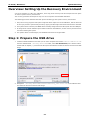
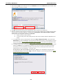
Step 1: Prepare the USB drive .............................................................................................................. 6-2
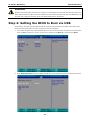
Step 2: Setting the BIOS to Boot via USB .............................................................................................. 6-4
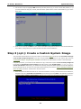
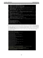
Step 3 (opt.): Create a Custom System Image ....................................................................................... 6-5
Step 4: Reset BIOS to Original State ..................................................................................................... 6-8
Step 5: Perform a Test Restoration ....................................................................................................... 6-8
A.
The 2013 Synmap OID Table ............................................................................................................. A-1
Moxa Synmap: The Full OID Table ........................................................................................................ A-2
B.
Sample Code for TC-6110 Customization........................................................................................... B-1
The LED Control Script ........................................................................................................................ B-2
The Accelerometer Control Script .......................................................................................................... B-4
Accelerometer Conversion Code............................................................................................................ B-6
The Watchdog Control Script ................................................................................................................ B-6
The Temperature Sensor Control Script ................................................................................................. B-7
1
1.
Introduction
Thank you for buying Moxa’s TC-6110 train computer. It comes with the Windows 7 Embedded software
platform, providing a simple and familiar development environment for on-board train applications.
Software Components
TC-6110 / Windows 7
Introduction
Software Components
Refer to the following content for the software components of the Windows Embedded Standard 7 pre-installed
on the TC-6110 computers.
Windows Embedded Standard 7
Core OS:
• 32-bit support
• Remote Client
• Remote Procedure Call
Applications and Services Development:
• .Net Framework 4.0
• Remote Desktop Protocol 7.1
• COM OLE Application Support
• COM+ Application Support
• MSMQ
Internet Services:
• Internet Explorer 8.0
• IIS 7.0
File Systems and Data Store:
• Windows Data Access Components
• Windows Backup and Restore
Diagnostics:
• Common Diagnostic Tools
• Problem Reports and Solutions
Fonts: Chinese (Trad. and Simp.), Western, Middle Eastern, South East Asian, and South Asian Fonts
Graphics and Multimedia:
• MPEG DTV-DVD Audio Decoder (MPEG-2, AAC)
• MPEG Layer-3 Audio Codecs(MP3)
• MPEG4 Decoders
• Windows Media Video VC-1 (WMV) Codecs
• DirectX and Windows Device Experience
• Windows Media Player 12
International:
• IME Simplified Chinese Support
• IME Traditional Chinese Support
Management:
• Group Policy Management
• Windows Management Instrument (WMI)
• Windows Update
Networking:
• Extensible Authentication Protocol (EAP)
• Internet Authentication Service
• Telnet Server
• Bluetooth
• Domain Services
• Network Access Protection
• Network and Sharing Center
• Quality of Service
• Remote Access Service (RAS)
• Telephony API Client
• Windows Firewall
• Wireless Networking
1-2
TC-6110 / Windows 7
Introduction
Security:
• Credential Roaming Service
• Credentials and Certificate Management
• Windows Authorization Manager (AZMAN)
• Windows Security Center
• Active Directory Rights Management
• Security Base
• Encrypted File System (EFS)
Embedded Features:
• Enhanced Write Filter (EWF)
• File-Based Write Filter (FBWF)
• Message Box Default Reply
• Registry Filter
• WSDAPI for .NET
Embedded Self-Health Diagnostic Software: SNMP-based remote scripting layer for monitoring, reporting,
and control
1-3
2
2.
System Initialization
This chapter describes how to initialize the system settings on TC-6110 computer when you boot up the
computer at first time.
The following topics are covered in this chapter:
Create a New User Account
TC-6110 / Windows 7
System Initialization
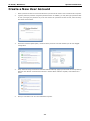
Create a New User Account
1.
2.
When you boot into the TC-6110 for the first time you will need to create a user account for this computer.
Type the password, and then retype the password below. In addition, you may also type a password hint
in case you forget your password. If you do not want to set a password for the account, leave the entry
box blank and click Next.
3.
Select the windows update option, and then select your time zone and whether you will use daylight
savings time.
4.
Next, select the usage environment. Windows will automatically apply a preset bundle of security settings
based on the network environment in which it is located. Most restrictive is public, least restrictive is
home.
5.
Now you can start to use TC-6110 embedded computer.
2-2
3
3.
Enabling Windows 7 Write Protections
This chapter describes how to set up and configure Windows 7 bit-level and file-level write protections on the
TC-6110 storage drives.
The following topics are covered in this chapter:
Enhanced Writer Filter
File-Based Write Filter
TC-6110 / Windows 7
Enabling Windows 7 Write Protections
Enhanced Write Filter
Overview
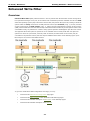
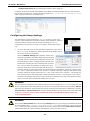
Enhanced Write Filter (EWF) allows Windows 7 users to protect their all information on their storage drive
from permanent changes of any sort, at the lowest level of hardware protection available: the bit level. EWF
allows the operating system (OS) to boot from the hard disk, but protects the system by creating a virtual file
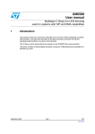
system called an overlay. All writes to an EWF-protected volume (the hard disk, in Fig. 1) are only recorded
on this virtual overlay (the EWF Volume, in Fig. 1), which is stored independently in random access memory
(RAM). Because EWF does not write data directly to the hard disk but instead only records system writes to this
virtual RAM overlay, any data that is “written” during system operation will disappear upon the next re-boot.
This approach allows the system to operate as if it is writeable when in reality all OS and user-space file
systems are stored in a permanent, read-only state. If desired, the data written to the overlay may be
committed to the protected volume, but this requires additional effort. Refer to the following figure (from
Microsoft) for an overview of the EWF structure.
To get more details about EWF configuration and usage, you may:
•
Visit Microsoft’s EWF Volume Configuration help pages.
•
Visit Microsoft’s EWF overview on the official Microsoft EWF help pages.
•
Visit Microsoft’s detailed description of EWF modes on the EWF help pages.
•
Visit Microsoft’s detailed description of the EWF API.
3-2
TC-6110 / Windows 7
Enabling Windows 7 Write Protections
Enabling Enhanced Write Filter
Follow these steps to enable the Enhanced Write Filter
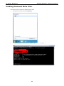
1.
First open the console by running cmd.exe.
2.
To verify that Enhanced Write Filter is disabled, type C:\....>ewfmgr c:.
3-3
TC-6110 / Windows 7
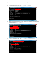
3.
4.
Enabling Windows 7 Write Protections
To enable the Enhanced Write Filter, type C:\....>ewfmgr c: -enable.
Reboot the system so the changes may take effect, and then verify that Enhanced Write Filter has been
enabled at boot by typing C:\....>ewfmgr c:
5.
To disable the Enhanced Write Filter, type C:\....>ewfmgr c: -commitanddisable.
3-4
TC-6110 / Windows 7
Enabling Windows 7 Write Protections
File-Based Write Filter
Overview
File-Based Write Filter (FBWF) is similar to EWF, but is enforced at the file level rather than at the hardware
(bit) level. This means it is slightly less secure, but this allows it to provide more user features than is possible
with EWF.
File-Based Write Filter (FBWF) allows the Windows Embedded platform to maintain the
appearance of read and write access on write-sensitive or read-only storage. FBWF
makes read and write access transparent to applications.
Writing to storage media may be undesirable or impossible in embedded devices. FBWF
redirects all writes targeted for protected volumes to a RAM cache called an overlay. Used
in this context, an overlay is similar to a transparency overlay on an overhead projector.
Any change made to the overlay affects the picture as seen in the aggregate, but if the
overlay is removed, the underlying picture remains unchanged.
One of FBWF’s more advanced features allows the user to specify a directory where data may be more
conveniently written to the data drive than is possible with EWF. The TC-6110’s default settings have already
configured a default directory for this; you may use the c:\temp directory for files which require write access.
Enabling File-Based Write Filter
To enable file-based write filtering, do the following:
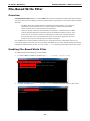
1.
To check if FBWF is enabled or disabled, type C:\...\>fbwfmgr /displayconfig:
2.
To enable the FBWF, type C:\...\>fbwfmgr /enable and then reboot the system to take effect.
3-5
TC-6110 / Windows 7
3.
Enabling Windows 7 Write Protections
After the system has rebooted, type C:\...\>fbwfmgr /displayconfig again to check if the status
has been changed to enabled and will start at boot-time.
To get more details about EWF configuration and usage, you may:
Go to Microsoft’s FBWF Installation and Configuration help pages.
Go to Microsoft’s FBWF overview on the official Microsoft EWF help pages.
Go to Microsoft’s detailed description of FBWF features on the EWF help pages.
Go to Microsoft’s detailed description of the FBWF API.
3-6
4
4.
Installing Moxa Software
This chapter describes how to configure and install the bundled Moxa software that comes with the TC-6110.
Moxa software allows users to build scripts and custom software to automatically or remotely control and
monitor the TC-6100 for both process- and infrastructure-level needs.
The following topics are covered in this chapter:
mxhtsp: Hot Swapping for Hard Drives
Overview
Installing mxhtsp
Hot Swap Configuration and Usage
Moxa Predictive Maintenance Diagnostic Tools
Overview
Installing the PdM Diagnostics Package
Configuring and Using the G-Sensor Tool
Configuring and Using the Temperature Sensor
The Synmap™ Virtualization Layer: Full Interoperability with Any Moxa Device
Overview
The Synmap Design Concept
Moxa Synmap OIDs List
Installing the Synmap Virtualization Layer
Installing and Using an NMS
Installing Moxa MxView
Basic Configuration of MxView
Loading the Synmap MIB File
Using Synmap OIDs to Control the TC-6110
TC-6110 / Windows 7
Installing Moxa Software
mxhtsp: Hot Swapping for Hard Drives
Overview
The TC-6110 comes with an eight gigabyte CompactFlash card specifically included as permanent storage
space for the operating system and system software. The TC-6110 also comes with two removable modules
that each support a single SATA 2.5 inch HDD/SSD interface; additionally, the TC-6110 comes with two empty
modules for further memory drive expansion, if so desired. The mxhtsp software package makes these
modules hot swappable, so they may be safely removed during computer operation without powering down. To
enable the TC-6110’s hot swap feature, users must install mxhtsp by following the instructions below.
Installing mxhtsp
Follow these steps to install mxhtsp and enable the TC-6110’s hot swap capabilities.
1. Navigate to the Utility folder, located on the software DVD under <software DVD>\utility\1.mxhtsp\.
Double click mxhtsp_setup.msi.
2. When the software setup wizard appears, click Next to continue. In the next dialog, click Browse to select
the folder where you want to install the package, or simply click Next to continue if you want to use the
default folder.
3. The wizard will tell you the installer is ready to install mxhstp. Click Next to continue, and after the
installation has completed, click Close to exit the wizard and end the installation.
4. After the wizard closes a dialog will appear (seen at right) asking you if
you want to restart the system. Click Yes to restart the computer and
start the hot swap daemon, or click No if you prefer to continue
installing other software before restarting.
Hot Swap Configuration and Usage
Once the system has re-initialized you may follow the directions below to configure hot swap for your needs.
Starting Hot Swap
When Moxa’s hot swap daemon (mxhtspd) has automatically started at boot
time users will be notified by a message delivered in the Windows system tray.
Once mxhtspd is active, it will monitor the removable drives. Two features
are provided by mxhtspd, described below.
4-2
TC-6110 / Windows 7
Installing Moxa Software
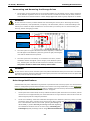
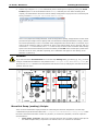
Unmounting and Removing the Storage Drives
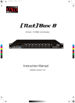
1.
On the spine of each module there is an inset button labeled X1; this button may be custom-configured,
but by default it signals the OS to un-mount the hard drive so that the module may be safely removed.
Users should use a small screwdriver or other sharply tipped instrument to gently depress the X1 button.
WARNING
Do not remove the memory modules without first unmounting the memory drive. Removing the memory
modules prematurely could permanently corrupt any or all stored data, and force a full reformatting of the
memory drive. Follow the steps described here to ensure that your memory drive is removed safely and
securely, without damaging your data.
Hot swap button
of disk 1
Hot swap button
of disk 2
2.
Once the system recognizes the button has been depressed, a notification
box will appear in the Windows system tray (shown at right) informing the
user that the button has been pressed.
3.
Once the system has successfully un-mounted the hard drive, another
notification window will appear (shown at right) in the Windows system
tray, informing the user that the disk has been successfully unmounted.
Only now is it safe to remove the memory drive module.
WARNING
Do not remove memory drives until the system has posted notification that they drive has been successfully
unmounted. Removing the drives without first ensuring they have been unmounted will result in corrupted data
that may cause the loss of the entire drive.
Drive Usage Notifications
Administrators may set a notification to signal when a specified amount of memory space on a drive has been
filled. For configuration procedures that describe how to set the drive usage notification, see the Configuring
Drive Settings Using mxhtspd: Hot Swap section, just below. Once the memory drive has been filled to the
level configured by the administrator, two notifications will appear.
1.
On the spine of the module itself, the array of LEDs will uniformly blink three times in succession, and will
continue to do so at approximately one minute intervals for as long as the drive continues to increase its
data storage beyond the configured parameter.
2.
On the user’s desktop, a Disk Info notification will appear in the Windows system tray, telling you what
percentage of the disk is currently used, and how much this is greater than the configured notification
level. The notification will be in the format [total percentage of
drive used] > [user-defined percentage of drive capacity].
The notification should be read as if it were saying “Currently your
total usage is [total percentage of drive used]; this has exceeded the
4-3
TC-6110 / Windows 7
Installing Moxa Software
configured parameter of [user-defined percentage of drive capacity].”
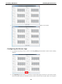
In addition to these two default responsibilities of the Moxa Hot Swap (mxhtspd) daemon, users may also
execute their own actions by creating and storing scripts in the C:\Program Files\MOXA\mxhtsp\script
folder, which is shown in the screenshot below.
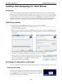
Configuring Hot Swap Settings
The default drive volumes monitored by mxhtspd are the D: and E: drive
volumes. If the administrator would like to change these settings by adding or
cancelling volumes, then this may be done by accessing the mxhtspd
configuration menu from the hot swap icon located in the Windows system
tray. .
1.
To access the setup menu for the Moxa Hot Swap daemon, right-click on
the mxhtspd icon located in the systray (Windows at the bottom right of
the screen and then select Setting.
When the MXHTSP Settings dialog appears, admins must
select the drive letters under which the storage drives will be
mounted. If the drives have been partitioned, select only the
first available drive letter; selecting anything else will cause
trouble when mounting the device. Windows will mount the
drive volumes under the identifiers you assign here. Once
assigned, these values will be associated with the device’s
hardware address, so that if the modules are removed and then immediately replaced in a different order
(i.e., drive 1 is placed in the Disk 2 slot, and drive 2 is placed in the Disk 1 slot) they will continue to be
mounted under their original volume name (i.e., drive 1 will continue to be volume D:, even though it is
now mounted in slot 2, and similarly Disk 2 will be mounted as volume E:, even though it is now in slot 1).
If admins wish to change this behavior, they may also do by creating a new entry in the Windows registry.
There are several online tutorials that explain how to do this.
WARNING
If the storage drive is partitioned into multiple volumes, then when configuring mxhtspd you must specify only
the first volume listed in the setting dialog. This volume will correspond to the drive’s first partition. DO NOT
select any other partitions, otherwise the drive will not mount and unmount properly. Additionally, checking
Execute Script and Check Partition will only affect the first partition and may not be used on the subsequent
partition(s). For these reasons, Moxa recommends against partitioning the drives used in the
TC-6110 SATA modules.
WARNING
If you tick the Check Partition box in the hot swap Settings dialog you must configure a notification threshold
for each partition in the C:\Program Files\MOXA\mxhtsp\config file (see below, pg. 4-4). If you do not,
mxhtspd will fail to read the partition and throw an error by notifying the user that Disk X does not exist
(with X representing the volume identifier that Windows is using to mount the drive).
4-4
TC-6110 / Windows 7
2.
Installing Moxa Software
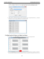
Admins may configure mxhtspd to automatically check remaining drive capacity by ticking the Check
Partition option. To set the threshold at which mxhtspd will notify the user about remaining drive
capacity, the administrator will need to edit the mxhtsp configuration script (seen in the screenshot just
below), located at C:\Program Files\MOXA\mxhtsp\config.
This is a very simple ascii configuration file; to set the target drive capacity, simply note the volume mount
point and the percentage of drive capacity that must be filled for mxhtspd notifications to begin, with the
two values separated by a colon. A screenshot of the configuration file is shown above. For example, if you
wish to set the system to notify you when the D: drive is 50% full and the E: drive is 90% full, then you
would enter D: 50 on the first line, and E: 90 on the second, as shown in the screenshot. When storage
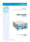
space on the drive has been filled beyond these thresholds, the L1 LED on the module spine (visible on the
front face of the TC-6110) will blink repeatedly, and a notification will appear on the desktop, in the
Windows 7 system tray.
WARNING
If you have ticked the Check Partition box in the hot swap Settings dialog (see above, pg. 4-3), you must
configure a notification threshold for each partition in the C:\Program Files\MOXA\mxhtsp\config file.
If you do not, mxhtspd will fail to read the partition and throw an error by notifying the user that the drive in
question “does not exist.”
L1 of Drive 1
L1 of Drive 2
X1 of Drive 1
X1 of Drive 2
Moxa Hot Swap (mxhtsp) Scripts
There are three Visual Basic scripts provided for customizing the Moxa hot swap feature. The hot swap
customization scripts are stored as files in the C:\Program Files\MOXA\mxhtsp\config\script\ folder.
Each file is associated with either module one (X1/disk1) or module two (X2/disk2). The three scripts are
described below:
•
action_btnX*_press.vbs: This script is executed whenever the X1 button (located on the spine of
the SATA storage module) is depressed. The default action is to unmount the hard disk1.
4-5
TC-6110 / Windows 7
•
Installing Moxa Software
action_disk*_plugged.vbs: This script is executed whenever the SATA module is mounted by the
TC-6110. The default action of this script is to flash LED 1 three times just after the drive has been
successfully mounted.
•
action_over_usage_disk*.vbs: This script is executed whenever the storage quota (as set in
mxhtspd.conf; see above, Configuring Hot Swap Settings) for the drive in question is reached.
The default action of this script is for LED 1 to flash 3 times, approximately once every minute.
All of these scripts are authored in Visual Basic and may be freely modified by the user. For instance, if a
systems administrator wishes to modify how storage quota notifications are delivered, s/he may edit the
action_over_usage script that corresponds to the appropriate drive.
Hot Swap (mxhtsp) Logs
Hot swap events and errors log files are found at C:\Program Files\MOXA\mxhtsp\log. Each log file is
automatically updated every 24 hours at midnight, and tagged with the date it is created. Inside, file events are
logged with the date and time the events occurred.
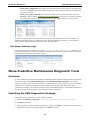
Moxa Predictive Maintenance Diagnostic Tools
Overview
TC-6110 computers come with Moxa’s predictive maintenance (PdM) diagnostic utilities software; this package
includes two tools: the G-sensor charting tool, and the hardware monitor interface. The G-Sensor
charting tool allows you to monitor and record the vibrations that the system experiences over time, allowing
administrators to anticipate and take precautions against conditions that might damage the system
(particularly hard disks). The hardware monitor interface allows administrators to view hardware information
like CPU frequency, drive temperature, and many other system parameters.
Installing the PdM Diagnostics Package
Follow these steps to install the G-sensor (vibration) package.
1. Double click mxsensor_setup.msi in <software DVD>\utility\2.mxsensor\Utility\.
2. Click Next to continue.
3. Select the folder you want to install the package to, or simply click Next to continue if you want to use the
default folder. When the next dialog appears, click Next to continue.
4-6
TC-6110 / Windows 7
Installing Moxa Software
4. When the installation is finished, click Close to complete the installation. Please remember that the PdM
diagnostics package will not be available until the computer is rebooted. You may restart the computer at
this point, if you wish.
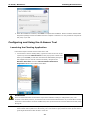
Configuring and Using the G-Sensor Tool
Launching the Charting Application
Follow these steps to launch and check the sensor tool.
1. To launch the G sensor charting utility, right-click on the tricolor icon in the
system tray and select GSensorChart from the pop-up menu. Please note
that if you select Exit you will shut down the Moxa PdM utilities package. If
this happens and you want to re-launch the utility, navigate to the
Windows Start Menu and select Moxa Predictive Maintenance
Diagnostic Tool from the software listed there.
ATTENTION
Users are advised that the accelerometer script returns vibration readings in milligravities (mG). The
G-sensor’s raw values, however, are returned in an unconverted hexadecimal form. If you would like to directly
access the G-sensor data in a human-readable form, then you should access G-sensor data from the GUI, using
the log file.
2. Next, verify that each initial value (X-axis, Y-axis, Z-axis) is close to 0 (+-100). The X-axis represents
front-to-back motion (relative t to the sensor), the Y-axis is left-to-right, and the Z-axis is up-and-down. A
good target threshold to start off with is 1000 mG.
4-7
TC-6110 / Windows 7
Installing Moxa Software
3. Finally, vigorously shake the computer and check if the vibration registers on the charts.
Configuring the Sensor Logs
1.
To configure log settings for the G-sensor, select Log Setting from the bottom of the G-sensor charting
interface.
2.
The LogSetting interface allows you to turn the G-sensor’s data logger on and off. To turn on the G-sensor,
enter the file path where you want the log saved, set the maximum file size (after which a new log file is
4-8
TC-6110 / Windows 7
Installing Moxa Software
created), and set the sampling interval (how often the vibration data will be sampled and recorded). When
finished, click Save to complete the setup. Note: Disk1 refers to slot 1, and Disk2 to slot 2.
3.
Wait for about 1 minute for the logger to start, and open the log in a simple ASCII editor (e.g.: Windows
Notepad) to verify it is logging information to the indicated path.
Configuring the G-Sensor to Signal an Alarm
1. To set an alert, select Alert Setting from the bottom of the G-sensor charting interface.
2. When the AlertSetting interface appears, it will look like the screenshot below. Generally, for industrial
hard drives built with high tolerance for vibration and shock, a good point to begin with is 1000 mG (1 G)
4-9
TC-6110 / Windows 7
Installing Moxa Software
although many drives can go as high as 20,000 mG (20 G). A suitable sampling rate to start off with is 100
ms. To get the best performance, check the drive specifications provided by the manufacturer and then
experiment to get the best results.
3. Click Save to finish the setup. Note: Disk1 refers to slot 1, and
Disk2 to slot 2.
4. Wait for about 1 minute for the G-Sensor alert utility to restart,
then shake the computer. Check the log in a simple ASCII editor
(i.e.: Notepad) to verify it is logging stats to the indicated path. If
no events are logged (or the file does not exist), then try adjusting
the alert threshold to a smaller value (e.g.: 500) and do it again.
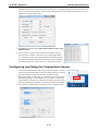
Configuring and Using the Temperature Sensor
1. To launch the temperature monitor, right-click on the tricolor icon in the
system tray and select the Monitor Tool from the pop-up menu. This will
open the monitoring utility user interface, as shown at right.
Please note that if you select Exit you will shut down the entire Moxa
PdM utilities package. If this happens and you want to re-launch the
utility software, navigate to the Windows Start Menu and select Moxa
Predictive Maintenance Diagnostic Tool from the software listed there.
2. The monitoring utility interface will appear as the screenshot below.
4-10
TC-6110 / Windows 7
Installing Moxa Software
The Synmap™ Virtualization Layer: Full
Interoperability with Any Moxa Device
Overview
Synmap™ is Moxa’s revolutionary software virtualization, an evolutionary advance in network device control
that adapts solid, reliable SNMP into a fully portable remote procedure interface. Synmap allows engineers to
automate remote processes using SNMP object identifiers (OIDs) rather than device- or OS-specific API
addressing, making a scripted Synmap procedure fully interoperable with any other Synmap device. This
means that a script created for one Synmap device may be directly copied to another, immediately conferring
the same functionality. This eliminates the need for rewriting and compiling code for newly configured devices,
significantly reducing maintenance and deployment times.
SNMP is lightweight and easy-to-configure, and is already long-popular with IT professionals; it also enjoys
comprehensive native support in high-level languages like .NET, Java, Python, or Ruby. For these reasons, the
Synmap framework has re-imagined SNMP as a universal configuration and control interface for remote
procedures, adapting it to not only monitor and control device internals like temperature, BIOS parameters,
and local interfaces, but also to report on and automate tasks at the process layer, as well. Easily integrated
into any existing Network Management System (NMS), Synmap devices are a flexible and cost-effective
upgrade that returns obvious benefits to any IA network.
Synmap currently allows you to use SNMP for remote monitoring and control of a select set of computer
processes, but its list of features is rapidly growing. Using Synmap’s fully portable scripts, engineers will soon
be able to:
Access, monitor, control, and report on digital I/O at both the process and hardware layers
Use OIDs to monitor, configure, and give process control over serial ports and other interfaces
Monitor and control system attributes and process events via any NMS
Build automated remote procedures using Synmap OIDs called by simple shell scripts, or a preferred
high-level language like Python, Perl, or VBScript—all without any need for low-level APIs, or
platform-specific libraries
Significantly simplify and reduce development times for custom utilities and automated executables
Gain scripting and automation independence from OS-dependent libraries
All of this may be achieved using simple, reliable, and familiar SNMP, the easily accessible standard that IT
engineers are already familiar with.
The Synmap Design Concept
Synmap is a software design concept that offers programmers a wholly unique and superior conception of
infrastructure development for IA control. Instead of using low level APIs, Synmap adapts the higher level
SNMP protocol to serve as a universal API across all machines. With Synmap, application developers gain
several benefits, the two biggest being a significantly reduced learning curve for control APIs and remarkable
code portability. For example, if a user wants to control GPIO in a Linux environment, an application developer
needs to generate code that follows the pseudo code shown below:
1. Open() the device node
2. Read() the file descriptor
3. Read() the return value, and make a logical decision
4. Perform an ioctl function on the file descriptor
5. Close() the file descriptor
The above example shows how this is done in a *NIX environment. In a Windows environment, it looks a little
different, but the process is essentially the same, and of equal complexity:
4-11
TC-6110 / Windows 7
Installing Moxa Software
1. Open a required file handle using mxgpio_open
2. Get data using the file handle, an assigned port, and mxgpio_get_data
3. Evaluate the returned data, and make a logical/control decision
4. Use mxgpio_set_data with the file handle to set a value
5. Use mxgpio_close to close the file handle
These examples show, in concise form, the difficulties application developers face when dealing with low level
APIs. Developers must understand each system’s API and track down various device node IDs from within the
user manual, the sample code, or the general system. Synmap significantly simplifies this situation. In
comparison to the example just shown, the pseudo code that replaces it will look something like this:
•
GET an OID using SNMP and the localhost connection (127.0.0.1)
•
Evaluate the returned data, make a logical decision
•
SET an OID using SNMP and the localhost connection (127.0.0.1)
The benefits of using SNMP in this way should be clear.
•
First, the code is easily migrated across different computers and even different operating systems, because
Moxa’s SNMP libraries are supported on both Windows XPE and Linux, as well as a host of other platforms.
•
Second, the program can just as easily be ported to the network for remote operations simply by changing
the localhost connection (127.0.0.1) to the target IP address and hostname.
•
Third, the time needed to learn how to control a peripheral is drastically cut; all one needs to do is
•
Fourth, Developers are free to choose any kind of programming languages or utilities with which they might
understand how to use an SNMP OID, and start scripting.
be familiar, so long as they are apropos to the platform(s) on which they will be used. For example, in place
of the C API, Microsoft developers might want to use the SNMP libraries in .NET or Java to control remote
Linux devices, or it can be flipped around so that Linux developers use Net-SNMP libraries to control remote
Windows XPE machines.
All of these things mean that the Synmap virtualization makes the work of programming custom applications
much faster and simpler, and dramatically increases code interoperability. Complex controls such as USB notify,
mounting information, and BIOS settings have been integrated into the Synmap engine, so that creating a
customized monitoring or control application now only requires the coordination of a few SNMP SET/GET calls,
potentially allowing developers to save on hundreds of lines of code when authoring new applications.
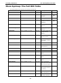
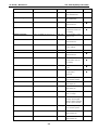
Moxa Synmap OIDs List
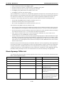
The following table shows the OIDs currently supported on the TC-6110. For a full review of all Moxa Synmap
OIDs, check the Appendix section.
Item Name
OID
Access
Description
productName
1.3.6.1.4.1.8691.17.1.1.1
read-only
Returns the product name
productDesc
1.3.6.1.4.1.8691.17.1.1.2
read-only
Returns a short device description
productVersion
1.3.6.1.4.1.8691.17.1.1.3
read-only
Returns product version
productBuildDate
1.3.6.1.4.1.8691.17.1.1.4
read-only
Returns the last software build date,
YYMMDDHH format
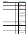
tempSensorsIndex
1.3.6.1.4.1.8691.17.1.5.1.1.1.1
read-only
Reference index showing all
available temperature sensors;
starts from 1
tempSensorsDevice
1.3.6.1.4.1.8691.17.1.5.1.1.1.2
read-only
Returns a list of the unique string
values that the database associates
with a temperature sensor index
value. May be used with
4-12
TC-6110 / Windows 7
Installing Moxa Software
tempSensorIndex to identify
temperature sensors by
name/position, and to subsequently
call them in scripts
tempSensorsValue
1.3.6.1.4.1.8691.17.1.5.1.1.1.3
read-only
The reading returned by the
thermometer, in degrees Celsius
Note: On the TC-6110, temp. is
currently represented as the current
reading truncated to its base
integer, without rounding
accelerometerIndex
1.3.6.1.4.1.8691.17.1.5.1.3.1.1
read-only
Reference index showing all
available accelerometers; starts
from 1
accelerometerAxis
1.3.6.1.4.1.8691.17.1.5.1.3.1.2
read-only
Shows the format in which
accelerometer’s axial values will be
returned. This will always be in Xn Yn
Zn form, with n the index number of
the accelerometer with which the
axis is associated
accelerometerValue
1.3.6.1.4.1.8691.17.1.5.1.3.1.3
read-only
Returns a block of the last hundred
recorded values for all three axes of
a particular accelerometer, taken
from the log file; this will be g-force
in micro gravities (µG).
Note: this OID requires the
accelerometer’s log file to be
activated and up-to-date. If the log
file is unreadable for any reason,
this OID will not return data.
accelerometerTimestamp
1.3.6.1.4.1.8691.17.1.5.1.3.1.4
read-only
Returns the accelerometer
timestamp
usbDeviceProductID
1.3.6.1.4.1.8691.17.1.6.4.1.3.1.3
read-only
Returns the USB’s hexadecimal
product ID
usbDeviceActiveClass
1.3.6.1.4.1.8691.17.1.6.4.1.3.1.4
read-only
Returns the USB device class for any
connected device
watchdogPeriod
1.3.6.1.4.1.8691.17.1.6.6.2.1
read-write
Sets the watchdog’s timeout
interval, in seconds:
•
Entering 0 disables the
watchdog
•
Entering an integer from 1 to
255 configures the timeout
interval to that number of
seconds
watchdogStatus
1.3.6.1.4.1.8691.17.1.6.6.2.2
read-write
Returns the watchdog’s current
status and timeout interval
powerPolicy
1.3.6.1.4.1.8691.17.1.7.2
read-write
Returns the system’s current power
policy, as configured by the
Windows 7 Embedded OS
4-13
TC-6110 / Windows 7
Installing Moxa Software
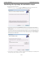
Installing the Synmap Virtualization Layer
The following steps will install Synmap.
1. Double click mxSynmap_setup.msi, found in the Utility folder located on the software DVD under
\utility\3.mxSynmap\. Then click Next to start the Synmap setup wizard.
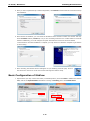
2. In the middle of the dialog, the button Disk Cost will display how much space the Synmap software
package will occupy on your storage drive, as well as the remaining storage space on the drive where the
system is stored.
At the bottom of the dialog, select whether Synmap will be installed for every user across the entire system,
or just for the current user account. Above that (in the text dialog), you may click the Browse button to
browse the file tree and select the folder where you want to install the package, or simply click Next to
install Synmap to the default folder.
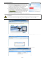
3. Click through the next few dialogs to complete the installation of the Net-SNMP agent. The SNMP agent will
not begin working until you reboot the TC-6110 computer.
4-14
TC-6110 / Windows 7
Installing Moxa Software
Installing and Using an NMS
For full implementation, Synmap requires (like any SNMP-based system) an NMS to become fully functional; an
NMS with an MIB browser also makes using SNMP a far simpler task. If you already have your own MIB browser,
you can skip this section. However, if your network is lacking an NMS then you may install a free version of
Moxa’s MXview to get Synmap up and running. MXview provides an MIB browser and an interface that will
allow you to monitor and control any Synmap enabled device. This section will walk you through a basic MXview
installation, and show you how to use the MXview MIB browser to start working with the TC-6110’s MIB.
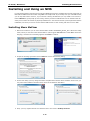
Installing Moxa MxView
1. MXview is included on your TC-6110 software DVD. Double click mxView_Trial_V2.3.msi in the Utility
folder, which you can find on the software DVD in \utility\4.mxViewTrial. Select OK to choose the
language, and when the next dialog appears click Next to continue.
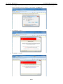
2. Accept the licensing agreement and click Next to move to the licensing dialog.
3. On the next dialog you may change the folder and path where MXview will be installed. On the next, you
may select where MXView shortcuts will be stored in the Windows Start Menu.
4. Next, you may register MXview as a Windows service and create a desktop shortcut.
4-15
TC-6110 / Windows 7
Installing Moxa Software
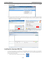
5. After you have completed the pre-install configuration, click Install to transfer MXview to disk and wind up
the installation.
6. After MXview has installed, you must enter the IP address of the machine on which it is located. This may
be the localhost address, 127.0.0.1, or if you are connecting to MXview over a LAN it will be a remote IP
address. Additionally, you must configure the ports which MXview will use for HTTP and HTTPS
communications. Once the installation is complete, you may choose to restart the computer to get MXview
up and running
7. After rebooting, the MXview shortcut will appear on your desktop (shown at right). Click on
the shortcut to continue on to the next section and begin the MxView setup.
Basic Configuration of MxView
1. Open MXview (see step 7 of the last section, immediately above) and select Start to initialize the MXview
NMS; wait for the System Status notification to change to Running, then click Launch Client.
4-16
TC-6110 / Windows 7
Installing Moxa Software
2. If opening Microsoft Internet Explorer for the first time, make
sure to turn off the suggested sites feature (shown at right). If
you wish to use another browser you may, and IE’s other
settings may be configured to your own preferences.
3. The IP address for MXview will be 127.0.0.1 followed by a colon
and the HTTP port you configured MXview to communicate over
(in step 6 of MXview). If you have used the suggested settings
above, then to login using HTTP would be 127.0.0.1:81, and
using HTTPS you would use 127.0.0.1:443.
For the login, the default username is admin, with a blank password.
WARNING
For security’s sake, Moxa strongly recommends resetting the password to a strongly secure
password of at least 8 characters, mixing numbers and symbols in a non-word series.
4. When opening your browser for the first time, a warning message will pop up telling you to install the Java
runtime environment. Click OK to continue.
5. Click the title bar, and select File Download Blocked-->Download File to continue.
4-17
TC-6110 / Windows 7
Installing Moxa Software
6. Select Run to download and install the Java Runtime Environment (JRE), and when Windows posts a
security warning asking if you wish to run the installer, click Run again.
7. Click Install to continue.
8. Click Close to complete.
4-18
TC-6110 / Windows 7
Installing Moxa Software
9. In Windows IE, a banner will appear at the top of the browser window. Click the message and select Enable
Intranet Settings.
10. A security warning will appear, telling you that intranet settings are not secure enough for the open Internet.
Click Yes to ignore this, and when another security warning appears telling you that the application’s digital
signature is not recognized, click Run.
11. The Moxa MXview Setup Wizard will now appear. You may click Next if you wish to enter the setup
routine, or select Cancel to launch the program immediately.
If you click Cancel, The program will be launched. It should look like the screenshot below.
Loading the Synmap MIB File
To load the Synmap MIB file you must first have a running NMS; if you do not have an NMS, you may install the
free version of MXview included with your TC-6110 computer software. If you have already started MXview, go
directly to step 5 of this section.
1.
Click the MxView Service shortcut on the desktop.
4-19
TC-6110 / Windows 7
2.
Installing Moxa Software
Click Start, wait for the System Status indicator to show Running, and then select Launch Client. When
the MXview Setup Wizard appears, click Cancel to skip the setup process and directly open the MXview
interface.
3.
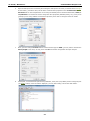
Select MIB-->MIB Browser.
4.
After the MIB browser has opened, select File from the browser’s upper left corner, and then Load MIB.
(Instructions continue on next page)
4-20
TC-6110 / Windows 7
5.
6.
Installing Moxa Software
Navigate to c:\usr\share\snmp\mibs\ and select MOXA-SYS-MIB.txt.
After opening the Synmap MIB in the browser, check that it appears in the File window. If it is not, then
it is likely because the MIB file is corrupted. To remedy this, re-copy the MIB file from the software DVD,
and re-load the MIB file following the instructions above.
4-21
TC-6110 / Windows 7
Installing Moxa Software
Using Synmap OIDs to Control the TC-6110
Follow these steps to use Moxa Synmap to read the MIB and set up controls for the TC-6110.
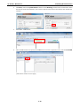
Retrieving Basic Device Information
1. In this first step, we will use Synmap to retrieve specific device information about the TC-6110.
First, use the Get Next button to navigate the OID tree by clicking through these items:
MOXA-SYS-MIB\VALUES\Moxa\embeddedComputer\MoxaSystem\productInfoMgmt
2. When you reach the final layer of OIDs, you will need to select GetSubTree to display the available
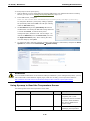
information. When you use the MIB viewer to select the productInfoMgmt OID, you will see the following
information displayed in the MIB viewer’s information window: Product Name (TC-6110), Product
Description (Moxa embedded computer), Product Version (1.0.0), and Product Build Date
(13013018).
4-22
TC-6110 / Windows 7
Installing Moxa Software
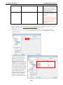
Using Synmap to Control the Programmable LEDs
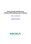
The following figure shows the locations of the LED indicators on the TC-6110 computer. Using custom scripts,
you can set these LEDs to be used as indicators for your own applications.
LED1
LED2
LED7
LED5
LED3
LED8
LED6
LED4
The following table shows the available OIDs for the TC-6110 LEDs.
Item Name
OID
Access
Values
Description
ledNumber
1.3.6.1.4.1.8691.17.1.6.2.1
read-only
N/A
Returns the total number of
LEDs
ledIndex
1.3.6.1.4.1.8691.17.1.6.2.2.1.1
read-only
N/A
Returns a list of numbers that
correspond with the LEDs,
used by SNMP to identify the
LEDs; begins with 1
ledPort
1.3.6.1.4.1.8691.17.1.6.2.2.1.2
read-only
N/A
Returns the names by which
the index of LEDs may be
called when used in scripts;
begins with 0
ledValue
1.3.6.1.4.1.8691.17.1.6.2.2.1.3
read-write
0(off), 1(on)
Returns/sends a value
indicating/changing the LED
state
Follow these steps to configure the programmable LED indicators on the TC-6110 computer.
1.
Start up MXview (or some other NMS) and open
the MIB browser. For detailed instructions on
loading MXview, you may refer to Loading the
Synmap MIB File, steps 1 to 3.
2.
In the MIB browser, navigate the OID tree to
MOXA-SYS-MIB\VALUES\Moxa\
embeddedComputer\MoxaSystem\
peripheralMgmt\perLedMgmt\ledTable\
ledEntry\ledValue. To change the state of
an LED from on to off (or vice versa) click Set on
the corresponding ledValue OID (shown in the
figure at right). This will open a dialog called the
Set Value dialog.
4-23
TC-6110 / Windows 7
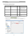
3.
Installing Moxa Software
The Set Value dialog has four fields: one for the OID
that is being called; another called Index, that identifies
the LED being manipulated; and a third called Value, to
set the state of the LED. The fourth field (Syntax)
informs you of the type of character to be used to set the
value. In this case, we are using the integers 0 and 1: 0
turns the LED off, and 1 turns it on. After entering the
correct information into the fields (as shown at right),
click on the Set button and check if the LED1 indicator
has lit up (LED 1 is shown in the figure at the top of this
section, Using Synmap to Control the
Programmable LEDs).
4.
Next, set the value to 0 and click Set to turn off the LED, then visually verify that the LED has successfully
turned off. If you experience problems at this point, please review the instructions above and if the
problem persists, contact Moxa technical support or visit our .
Using Synmap to Set the OS Power Policy
The following table shows the OID power policy control, read/write option and available values.
Item Name
OID
Access
Value to set
powerPolicy
1.3.6.1.4.1.8691.17.1.7.2
read-write
1(Balanced)
2(Power Saver)
3(High Performance)
The powerPolicy OID allows you to change the Windows 7 power policy. Balanced may be considered normal
operations, and except in extreme circumstances of exceptionally high CPU use or where strict energy
conservation must be maintained, this option will provide satisfactory performance. Power Saver will
conserve power usage to the maximum extent possible, restricting the CPU to around 36% capacity. High
Performance maximizes CPU cycles for all applications at all times; generally, High Performance is not
recommended, and in many (perhaps most) circumstances where the TC-6110 is used, Power Saver mode
may be adequate to the system’s needs. Sysadmins should carefully review the needs of the system and do
some quick tests to make the most informed decision. These settings may be further fine-tuned with advanced
choices in the Windows 7 OS.
4-24
TC-6110 / Windows 7
Installing Moxa Software
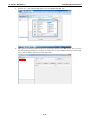
To use Synmap to set the power policy:
1.
Start up MXview (or some other NMS) and open the MIB browser. For detailed instructions on loading
MXview, you may refer to Loading the Synmap MIB File, steps 1 to 3.
2.
In the MIB browser, navigate to
MOXA-SYS-MIB\VALUES\Moxa\embeddedComputer\MoxaSystem\powerMgmt\powerPolicy.
To change the Windows 7 power policy settings, highlight
the powerPolicy OID and click Set. This will open a dialog
called the Set Value dialog.
3.
The Set Value dialog for the powerPolicy OID has two
variable fields: one showing the OID that is being called and
a second called Value, to indicate which power
management policy should be used. Use the integer 1 to
indicate the Balanced, 2 for the Power Saver, and 3 for
the High Performance policy. After entering the value,
close the dialog by clicking Set.
4.
To check if the policy has been changed, navigate to the Windows 7 Control Panel, and open the Power
Options tab, located under Control Panel System Security.
ATTENTION
For more detailed information on the advanced settings of Windows 7 power management policies, you may
refer to Microsoft’s online Windows support pages, which are currently (Jul. 2013) found at this link:
http://windows.microsoft.com/en-us/windows7/change-create-or-delete-a-power-plan-scheme
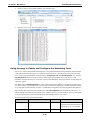
Using Synmap to Read the Temperature Sensor
The following table shows the temperature sensor OIDs.
Item Name
OID
Access
Description
tempSensorsIndex
1.3.6.1.4.1.8691.17.1.5.1.1.1.1
read-only
Returns a list of numbers
(beginning with 1) that
corresponds with the available
T-sensors; these identifiers
are used by SNMP and for
system scripts.
tempSensorsDevice
1.3.6.1.4.1.8691.17.1.5.1.1.1.2
read-only
Returns a list of string values
identifying the temperature
4-25
TC-6110 / Windows 7
Installing Moxa Software
sensors by name/location.
Possible values are SATA1,
SATA2, or CPU, for the CPU’s
internal thermometer.
tempSensorsValue
1.3.6.1.4.1.8691.17.1.5.1.1.1.3
read-only
The reading returned by the
thermometer, in degrees
Celsius.
Note: On the TC-6110, temp.
is currently represented as the
current reading truncated to
its base integer, without
rounding.
To use Synmap to check the temperature sensor (T-sensor) of the TC-6110 computer, follow the steps below.
1. Start up MXview (or some other NMS) and open the MIB browser. For detailed instructions on loading
MXview, you may refer to Loading the Synmap MIB File, steps 1 to 3.
2. Navigate to MOXA-SYS-MIB\VALUES\moxa\embeddedComputer\moxaSystem\sensorMgmt\
sensorObject\tempSensorTable in the MIB Browser, and then select Get Subtree to open the
T-sensor’s OID tree.
3. All of the T-sensor information
should now be displayed in the
MIB browser; if it is not, then
there is a problem with your
SNMP/Synmap configuration or a
malfunction in the T-sensor. The
temperatures are all displayed in
Celsius. In the screenshot below,
the temperature of disk 1 (SATA1)
is 37 degrees. If the SATA module
is not mounted, the temperature
value will be shown as 178
degrees. Thus, in the screenshot
at right, the disk 2 (SATA2) is
showing 178 degrees because
there is no disk mounted in slot 2
4-26
TC-6110 / Windows 7
Installing Moxa Software
of the computer.
Using Synmap to Read the G-Sensor
The following table lists the accelerometer OIDs.
Item Name
OID
Access
Description
accelerometerIndex
1.3.6.1.4.1.8691.17.1.5.1.3.1.1
read-only
Returns a list of numbers (beginning
with 1) that corresponds with the
available G-sensors; these
identifiers are used by SNMP and for
scripting
accelerometerAxis
1.3.6.1.4.1.8691.17.1.5.1.3.1.2
read-only
T
o
Returns the format in which
accelerometer axial values will be
returned. This will always be Xn Yn Zn
accelerometerValue
1.3.6.1.4.1.8691.17.1.5.1.3.1.3
read-only
Returns the accelerometer value
associated with a particular axis; this
c
will be g-force in micro gravities
h
(µG).
e
T accelerometerTimestamp
T
1.3.6.1.4.1.8691.17.1.5.1.3.1.4
read-only
Returns the G-sensor’s current
timestamp.
o
To use Synmap to read the vibration sensor (accelerometer, or G-sensor), follow these steps.
1.
Start up MXview (or some other NMS) and open the MIB browser. For detailed instructions on loading
MXview, you may refer to Loading the Synmap MIB File, steps 1 to 3.
2.
Navigate to MOXA-SYS-MIB\VALUES\moxa\embeddedComputer\moxaSystem\sensorMgmt
\sensorObject\accelerometerTable in the MIB Browser, and then select Get Subtree to open the
accelerometer’s OID tree.
4-27
TC-6110 / Windows 7
Installing Moxa Software
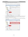
3.
Check to verify if logs for both GSensor1 and GSensor2 exist.
4.
Open the logs to verify they are logging correctly.
Using Synmap to Enable and Configure the Watchdog Timer
The TC-6110 comes with a default watchdog timer (a Computer Operating Properly/COP timer) that will initiate
a soft reboot whenever the system or a specific program freezes for a specified time period. The watchdog
timer has only two Synmap OIDs associated with it: watchdogPeriod and watchdogStatus. The value for
watchdogPeriod sets the countdown interval during which the watchdog timer must receive a COP
notification from the OS kernel; if it does not receive a COP notification during this interval, the watchdog will
reboot the system.
The default value of watchdogPeriod is 0, which leaves the watchdog disabled. To enable the watchdog timer,
you need to set the scanning interval to a non-zero integer between 1 and 255; this number will set the number
of seconds that will pass following a system (or application) hang before the watchdog reboots the platform.
After setting a time interval for the watchdog, the OID watchdogStatus will automatically change to 1, to
indicate that the watchdog timer is enabled. Once enabled, whenever the kernel fails to deliver a COP signal
during the specified time period the watchdog will automatically initiate a soft reboot.
The following table shows the watchdog OIDs.
Item Name
OID
Access
Value
watchdogPeriod
1.3.6.1.4.1.8691.17.1.6.6.2.1
read-write
An integer between 1 and 255
representing the timeout period in
seconds (E.g. 30 = 30 seconds)
watchdogStatus
1.3.6.1.4.1.8691.17.1.6.6.2.2
4-28
read
0 represents Off, 1 represents On
TC-6110 / Windows 7
Installing Moxa Software
To enable the watchdog via Synmap, follow the instructions below.
1.
Navigate to MOXA-SYS-MIB\VALUES\Moxa\embeddedComputer\MoxaSystem\
peripheralMgmt\systemWatchdog\watchdog period and select Set.
2.
In the Set Value dialog for watchdogPeriod, the refresh time can be entered as a number between 1 and
255 seconds in the Value field. Enter the desired value and click Set. Click OK when a dialog appears
indicating that the watchdog has been successfully set.
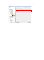
3.
Right-click MOXA-SYS-MIB\VALUES\Moxa\embeddedComputer\MoxaSystem\peripheralMgmt
\perSystemMgmt\watchdogStatus and select Get. Note that in the screenshot below, the watchdog is
currently disabled.
4-29
TC-6110 / Windows 7
4.
Installing Moxa Software
Since you have just changed the value of the watchdogPeriod OID, check to verify that the value of the
watchdogStatus OID has changed to 1. This means that the watchdog is now activated and running.
4-30
5
5.
Customizable Sample Code
This chapter uses sample code to show how scripting may be used to add customized capabilities to the
TC-6110 computing platform.
The following topics are covered in this chapter:
LED
Checking Programmable LED
Checking Vibration Status (SMBUS)
Enabling Watchdog Function
TC-6110 / Windows 7
Customizable Sample Code
Sample Code for Customizing the TC-6110
The TC-6110 computer comes with several pieces of sample code that users may use to customize its behavior
for LED notifications; temperature, vibration and GPS events; or to initiate emergency reboots when critical
system applications come to a halt.
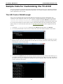
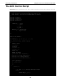
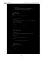
The LED Control Walkthrough
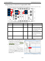
The TC-6110 is designed with 8 programmable LEDs that integrators and system administrators may
customize for their notification needs. The source code for controlling LED behavior is located in the folder
<Software DVD>\examples\project\LED\, while the compiled executable LED.exe is located under
<Software DVD>\examples\TC6000Release. You can follow the steps below to test the LED control script,
or you may freely modify the control script to create customized patterns that are associated with specific
system events. To review the LED control code, see The LED Control Script section in Appendix B of this
manual.
1.
Create the c:\programs\examples folder and copy LED.exe into that folder. Run LED.exe.
2.
You will be presented with a menu of three choices; first, select 1 to display the LED’s current status.
3.
In the screenshot below, the user has selected 1 and is viewing the current status of all LEDs. The value
0 shown next to each entry indicates that all of the LEDs are currently turned off. Visually verify this by
examining the TC-6110’s front panel.
4.
You may now run LED.exe again, but this time select 2. At the next prompt, enter the ID number (0 to 7)
of an LED to activate, and when prompted enter either 1 (to turn it on), or 0 (to turn it off). The LEDs on
the main TC-6110 panel correspond to 0 through 3; 4 and 5 correspond to those on the first module; and
6 and 7 to those on the second.
5-2
TC-6110 / Windows 7
Customizable Sample Code
G-Sensor/Accelerometer Control Code
The TC-6110 computer comes with 2 independent accelerometers that may be used to monitor external
vibrations affecting the computer. The accelerometers are located on the board of each of the two SATA
expansion modules. The basic accelerometer control code is included under the title G-Sensor.exe, and it may
be found on the software DVD under \examples\TC6000Release. The source code itself may be found
under \examples\project\GSensor\. To review the accelerometer control code you may refer to
Appendix B of this manual, under The Accelerometer Control Script.
You can follow the steps below to test the accelerometer. Please remember that the X-axis represents
front-to-back motion (relative to the sensor), the Y-axis is left-to-right, and the Z-axis is up-and-down. A good
target threshold to start off with is 1000 milligravities (mG), which is the basic tolerance threshold for many
industrial-quality hard drives.
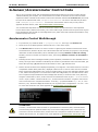
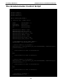
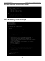
Accelerometer Control Walkthrough
1.
If you haven’t yet, create the folder c:\programs\examples, then copy over GSensor.exe.
2.
Insert the TC-6110 SATA expansion module into slot 1. Leave slot 2 empty.
3.
Run GSensor.exe and check to see if the G-sensor is registering raw vibration measurements. In the
screenshot below, because only the slot 1 SATA module has been inserted, the program is only showing
information for that accelerometer; this is indicated by the message GSensor on Disk1 is running.
Similarly, because no module is mounted in slot 2, the message GSensor on Disk 2 is unavailable is
displayed.
4.
Following the two sensor messages indicating sensor operation, information for each available sensor is
shown; the origin of the raw data is indicated by the number in parentheses at the end of the label, just
before the equal sign. (0) indicates the accelerometer in slot 1; (1) indicates slot 2.
5.
Data for each of the three axes is displayed separately, on a single line. The number shown is a raw two’s
complement notation binary data value, displayed in base ten form. This raw value must be converted
before it represents milligravities (mG). In the screenshot above, the only axis indicating vibration is the
z axis, which is showing 65517. To convert this number into milligravities, we must first convert it from
two’s complement representation and then multiply that result by a conversion ratio of 3.9 (base ten).
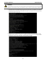
Using the number 65517, above, we first convert it to hexadecimal value. 65,51710 = 11111111111011012,
which is equal to FFED16. The left-most bit is a 1, so this means the number is a negative value and we
must convert from two’s complement notation. To do this, (-1)*(0xFFFF-0xFFED +1) = -1316, or -19 in
base ten (-1910). We then multiply this number by 3.910 to get the value in milligravities: -19 * 3.9 = -74.1.
To review the conversion code, check Appendix B, Accelerometer Conversion Code.
ATTENTION
G-sensor / accelerometer values are base 10 representations of raw binary data, and must first be
converted using bitwise operations before they can be read as milligravities (mG). The formula for
conversion is to first convert the binary number from two’s complement notation into base 10, then
multiply the result by 3.9. For sample code, check Appendix B, Accelerometer Conversion Code.
5-3
TC-6110 / Windows 7
Customizable Sample Code
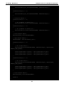
Watchdog Control Code
The code for controlling the watchdog/COP timer is the simplest and least-customizable of the included sample
scripts. The code itself is provided on the software DVD, under \examples\project\WatchDog\, and the
executable file Watchdog.exe is on the software DVD \examples\TC6000Release. This sample code may
be modified to integrate the watchdog timer with specific applications
Using this code any program may be set up so that the watchdog timer will provide a last-line failsafe against
application crashes. For instance, the TC-6110 may be set up so that whenever a mission-critical application
fails the watchdog timer will send a message to a system administrator and then initiate an automatic reboot.
To test the watchdog executable, follow the steps below.
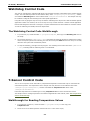
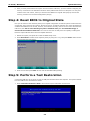
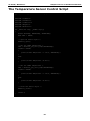
The Watchdog Control Code Walkthrough
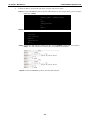
1.
If you haven’t yet, create the folder c:\programs\examples, then copy over Watchdog.exe and run
the script.
2.
The program will return *pdwPortVal = 0x80; this means the watchdog function is enabled and counting
down. To keep the system from rebooting, the user will need to press Enter at least once every 10 seconds,
otherwise the system will automatically reboot.
3.
To stop the watchdog, press q to exit the program. The watchdog timer control will return *pdwPortVal
= 0xc0, indicating that the watchdog timer is now disabled.
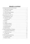
T-Sensor Control Code
The TC-6110 computer comes with built-in, independent temperature sensors that may be customized for
automated responses. The temperature sensor sample code may be found on the software DVD under
\examples\project\TempSensor\, and the executable file TempSensor.exe will be under
\examples\TC6000Release.
Follow the steps below for a walkthrough on using TempSensor.exe to return thermometer values.
The sample code for reading temperatures is included in Appendix B of this manual, under The Temperature
Sensor Control Script.
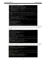
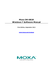
Walkthrough for Reading Temperature Values
1.
If you haven’t yet done so, create the folder c:\programs\examples then copy over
TempSensor.exe.
2.
Insert the TC-6110 SATA expansion module into slot 1. Leave slot 2 empty.
5-4
TC-6110 / Windows 7
3.
Customizable Sample Code
Run TempSensor.exe. The console should show the immediate values for the temperature sensors on
the SATA expansion module in slot 1 (43.88˚C, in the screenshot below) and slot 2. In this case, we have
inserted only one SATA module in slot 1, so the program only shows a value for Disk1; for slot 2 (Disk2,
below) it shows N/A (for Not Applicable), indicating that slot 2 is empty or the T-sensor is not operating.
GPS Control Code
A GPS module for the TC-6110 may be purchased from Moxa as an accessory. Moxa’s GPS receivers
communicate using the NMEA specification. This section describes how to build control scripts that automate
actions for particular GPS events. During this installation, we will use Moxa’s PCommLite serial
communications development environment to install and configure the GPS module. However, any serial port
terminal emulator (such as HyperTerminal, Tera Term, or PuTTY) may be used.
For more details about PCommLite, check the help menu that comes with the program. This help menu is the
full PComm manual, reproduced digitally and packaged with program.
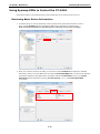
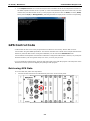
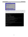
Retrieving GPS Data
To receive GPS data, follow the steps below:
1.
Connect the GPS antenna to the GPS antenna port on the TC-6110 front panel.
5-5
TC-6110 / Windows 7
Customizable Sample Code
2.
Identify the COM port number of the GPS in the device manager (the default port is COM3 )
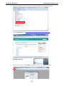
3.
Download PCommLite from http://www.Moxa.com/support/download.aspx?id=167.
4.
Install the program, and then call it from the
Windows Start Menu.
5.
Click the top left button (under Profile) to open the terminal’s port configuration dialog.
5-6
TC-6110 / Windows 7
6.
Customizable Sample Code
Open the GPS port in the terminal by first setting the COM port to the value you tracked down in step 2
of this section, just above. Next, set the basic communication properties in the Communication
Parameter tab. In the example below we are using the default port for the Moxa GPS module, COM3, at
115,200 baud. You should not need to change the other properties (Data Bits, Parity, etc), but if you do
(perhaps you are using another terminal that requires it) then refer to the figure below for details.
7.
Next, open the dialog’s Terminal tab and set the terminal type to ANSI (you may want to increase the
history depth to 500 lines, as well), then click OK to finish the configuration and open the port.
8.
At this point, a terminal should open showing GPS data; if not, then you probably need to change the port
(see step 6, above). Once the data is displayed, you may start writing code for the GPS module.
5-7
TC-6110 / Windows 7
9.
Customizable Sample Code
To allow the GPS to communicate with other programs, follow these steps:
Step1: Use the CreateFile()API to open the GPS COM port (in the example below, we are using the
default port, COM3).
HANDLE handlePort = CreateFile("COM3",
GENERIC_READ | GENERIC_WRITE,
0,
NULL,
OPEN_EXISTING,
0,
NULL);
Step2: Use the ReadFile() API to read GPS data from the COM port.
ReadFile(handlePort,
inputData,
inputDataSize,
gpsData,
&gpsDataSize,
NULL);
Step3: To parse the GPS data into another program, use the gpsData variable that was created in
Step 2. The data should look something like the example provided below:
Step4: Use the CloseHandle() API to close the GPS COM port.
5-8
6
6.
System Recovery
The TC-6110 ready-to-run embedded computers are a Windows Embedded Standard 7 platform. This chapter
describes the recovery process in the event of system instability.
The following topics are covered in this chapter:
Recovery Environment
Recovery Procedure
Saving the System to the USB Drive
TC-6110 / Windows 7
System Recovery
Overview: Setting Up the Recovery Environment
A TC-6110 computer, a 2 GB (min.) USB drive, and a copy of the recovery suite are all required to set up the
TC-6110’s system recovery environment.
The recovery procedure itself requires only a TC-6110 computer and a bootable USB drive.
The following procedure describes the basic process of setting up the system recovery environment.
1. First, the recovery programs and system image file will be copied over to the USB drive, and the drive will
be set up to provide a system boot process by copying an ISO image of the boot environment to the USB.
2. The system will be re-booted, and BIOS will be manually configured to boot the system from the USB port.
3. An image of the current software system will be created on the USB drive, for the recovery environment to
use when restoring the system.
4. The system will be re-booted again, and the BIOS returned to its original state.
Step 1: Prepare the USB drive
1. Load the software DVD that came with your TC-6110 computer and execute tuxboot-windows-23.exe
from the software DVD \recovery\TC6110W7E folder, select Pre-Downloaded, and click the button
marked with an ellipsis (…) to browse the file system and find the location of the boot environment’s ISO
image.
2. Navigate to \recovery\TC6110W7E\ClonezillaFactory_2013-02-21-14\ on the software DVD
and select the boot environment’s ISO image.
6-2
TC-6110 / Windows 7
System Recovery
3. Set the device Type (lower left-hand corner) as USB Drive, then set the Drive dialog to the letter under
which the USB is currently mounted.
4. Click OK, and the boot environment and bootloader will be copied to your USB drive.
5. Because of the file system naming conventions used, for any given computer only a single recovery image
may be used on any given USB drive. Consequently, at this point, users need to make a decision
about which sort of system recovery is preferred:
A.
a basic recovery of the root OS, or
B.
a recovery image of the fully configured OS, with all user-installed software applications and
scripts.
A. To configure the recovery environment to boot into a fully configured system, users should click
Reboot Now to close the installation environment and restart the computer. They should then proceed
to the next section, Step 2: Setting the BIOS to Boot via USB and continue the installation of the
recovery environment by continuing to Step 3 (opt.): Creating a Custom System Image.
B. To configure the recovery environment to boot into a clean OS image with no applications, users should
instead click Exit here to complete the installation and return to the OS. From within the desktop
environment, the user should then manually copy the directory containing the base OS from the
software DVD over to the USB drive. To do this, copy
#:\<Software DVD>\TC6110W7E\recovery\os_image over to the partition image directory,
F:\home\partimag\. At this point, Step 1 has been completed, and you should proceed to Step 2:
Setting the BIOS to Boot via USB.
6-3
TC-6110 / Windows 7
System Recovery
ATTENTION
Because of the peculiarities of the file tree naming, it is not possible to include both the base OS image and a
fully configured system image on the same USB stick. If users wish to configure both, then two USB drives must
be used, each configured according to the two different alternatives offered here.
Step 2: Setting the BIOS to Boot via USB
At this stage, users will reset the BIOS so that the system boots directly from the USB. This must be done
before the rest of the system recovery environment may be configured
1. Turn on the computer and, during the POST process, press F2 until you hear a long beep. You should then
enter the BIOS setup menu. Use the arrow keys to navigate to the Boot tab, and then press Enter.
2. Select Boot Type Order to open the dialog that will allow you to set the boot priority for the system drives.
6-4
TC-6110 / Windows 7
System Recovery
3. Use the arrow keys to highlight USB and then press the plus key (+) to move it to the first position, or (if
you want to take the long way around) select the other options above it and use the dash key [–] to move
them down.
4. Press F10 and then press Enter to save and exit the BIOS configuration interface. This should initiate the
next reboot, during which your system should now boot from the USB drive.
Step 3 (opt.): Create a Custom System Image
The instructions which follow are only to be used if you decided in Step 1 of this process to create a full copy
of an already-configured system. If you have not yet installed any software on your system, then return to
section 5b of Step 1: Preparing the USB Drive and follow the instructions to create a clean OS image.
Using this procedure, you will save to the USB drive a copy of the entire system as it is currently configured
to be used as a full system recovery image should the system crash. All files under F:\home\partimag\
will be overwritten. Additionally, you should have already changed the BIOS settings to make the USB drive
the first boot priority. If you have not yet reset the boot priority, first return to Step 2: Setting the BIOS to
Boot via USB, just above, and follow the directions there.
1. Once the system has launched and the TC-6110 has booted the recovery environment from the USB drive,
navigate to the entry Clonezilla Live Save Disk, and select it by pressing Enter. This will take you into the
recovery image creation environment, allowing you to copy your full system setup to the USB drive.
6-5
TC-6110 / Windows 7
System Recovery
2. The TC-6110 will now boot into the image creation environment. Wait for the boot process to finish.
3. Once the image creation environment has completed booting up, you will be given a warning and asked if
you wish to continue. Please keep in mind that if you create the recovery image, then any residual files
currently copied to the /home/partimag directory will be deleted. If there are any files remaining in
the USB partition image directory and you wish to save them, you must exit the recovery environment
and copy these files to another disk. If you wish to continue with the image creation, press Y (case
insensitive) to continue.
6-6
TC-6110 / Windows 7
System Recovery
WARNING
The same filename is used for all recovery images, whether for the full system backup or for the clean OS image
installation. This means that currently, it is impossible to have more than one system image per USB drive.
4. At this point, the recovery environment will copy of the entire hard drive to your USB drive. This will likely
take several minutes, and perhaps as long as half an hour. Do not remove the USB drive during this time;
wait patiently for the process to finish. Depending on the speed of your USB drive, this may be a good time
to get a cup of coffee, or take a nap.
5. At this point you may choose to power down the computer (press 0), reboot (press 1), enter a console
terminal (access a console TTY -- press 2), or re-initiate the entire procedure (press 3). Do not remove
the USB drive until you have rebooted or powered down the system.
6-7
TC-6110 / Windows 7
System Recovery
6. Once you have powered down the system and removed the USB drive, you have finished configuring the
recovery environment. The USB drive should be clearly labeled and stored in a safe place. You may now
continue to the next section, where you will return the BIOS to its original state (Step 4) and test the
recovery procedure for successful configuration (Step 5).
Step 4: Reset BIOS to Original State
Now you will need to return the boot priority to its original configuration so that the system will boot from the
original disk. This is done for two reasons; the first is security, so that the machine may not be rebooted from
unauthorized USB drives The second, however, is functional: currently, if the TC-6110 is set to boot from the
USB drive, then the TC-6110 will hang any time a USB data drive (i.e.: non-bootable image) is
inserted in the machine at boot time. The TC-6110 does not currently have the capacity to distinguish
between simple USB data drives and boot-capable OS drives.
1. Reboot the system, and press F2 to enter the BIOS setup menu.
2. Select Hard Disk and shift it to the top boot priority by using the + key, then press Enter. Make sure the
hard disk has first boot priority.
3. Press F10 and then press Enter to save and exit the BIOS settings dialog.
Step 5: Perform a Test Restoration
Connect the USB drive to any of the TC-6110’s USB ports and then reboot the computer. The system will boot
from the USB into the Clonezilla boot loader.
1. Select Clonezilla Live Restore Disk to boot into the system restoration environment.
6-8
TC-6110 / Windows 7
System Recovery
2. Wait for the boot process to finish.
3. At this point, the system will remind you that you are about to overwrite your entire operating system with
a new drive image, and ask you if you want to continue. When prompted, enter Y (case insensitive) from
the keyboard to start the system restoration process. Any other letter or Ctrl-C will cancel it and exit
Clonezilla.
4. The system will give you another warning that you are about to overwrite your hard drive, and erase all data
on the partition listed (sda1, in the example below). If you wish to continue, enter Y (case insensitive).
6-9
TC-6110 / Windows 7
System Recovery
5. Wait for the process to finish.
6. At this point, complete the restoration by selecting (0) Poweroff. This will shut down the computer; however,
if the Power Switch remains inserted in the front panel of the computer and is left in the ON position, then
the system fail to shutdown and will immediately initiate a soft reboot, instead. To avoid this, users may use
the switch to cut power to the computer immediately following the shutdown, or may simply remove the
power switch from the front panel and then use the console to shut down the computer by pressing 0.
7. After the computer has powered down, remove the USB drive and store it in a safe place.
6-10
A
A.
The 2013 Synmap OID Table
This appendix describes the full Synmap OID table as of July, 2013.
The following topics are covered in this appendix:
Moxa Synmap: The Full OID Table
TC-6110 / Windows 7
The 2013 Synmap OID Table
Moxa Synmap: The Full OID Table
The following table shows the full list of the Moxa Synmap OID.
Item Name
OID
Access
Description
productName
1.3.6.1.4.1.8691.17.1.1.1
read-only
Returns product name.
productDesc
1.3.6.1.4.1.8691.17.1.1.2
read-only
Returns product short
description.
productVersion
1.3.6.1.4.1.8691.17.1.1.3
read-only
Returns product version.
productBuildDate
1.3.6.1.4.1.8691.17.1.1.4
read-only
Returns product last
build date, the format is
YYMMDDHH.
systemCpuUsage
1.3.6.1.4.1.8691.17.1.2.1.1
read-only
Show CPU usage rate
(0-100 %).
systemMemUsage
1.3.6.1.4.1.8691.17.1.2.1.3
read-only
Show memory usage rate
(0-100 %).
systemUptime
1.3.6.1.4.1.8691.17.1.2.1.5
read-only
The amount of time since
this host was last
initialized.
systemTotalUptime
1.3.6.1.4.1.8691.17.1.2.1.6
read-only
The amount of time from
total boot up time.
systemMemorySize
1.3.6.1.4.1.8691.17.1.2.3.1
read-only
The amount of physical
main memory contained
by the host.
systemVolumeCount
1.3.6.1.4.1.8691.17.1.2.3.2
read-only
Show total volume count.
systemVolumeIndex
1.3.6.1.4.1.8691.17.1.2.3.3.1.1
read-only
Reference index for each
observed device.
systemVolumeName
1.3.6.1.4.1.8691.17.1.2.3.3.1.2
read-only
The name of the volume.
systemVolumeLabel
1.3.6.1.4.1.8691.17.1.2.3.3.1.3
read-only
The label of the volume.
systemVolumeSize
1.3.6.1.4.1.8691.17.1.2.3.3.1.4
read-only
The total size of the
volume.
systemVolumeAvail
1.3.6.1.4.1.8691.17.1.2.3.3.1.5
read-only
The available size of the
volume.
biosVersion
1.3.6.1.4.1.8691.17.1.4.1
read-only
Returns the BIOS
version.
biosSaveSetting
1.3.6.1.4.1.8691.17.1.4.2
read-write Write 1 to save bios
setting, and read 0 mean
setting had been applied.
biosSettingStatus
1.3.6.1.4.1.8691.17.1.4.3
read-only
Returns compare of bios
CMOS setting and bios
new setting.
bootDeviceStatus
1.3.6.1.4.1.8691.17.1.4.4.1
read-only
Returns the current
support boot device.
firstBootDevice
1.3.6.1.4.1.8691.17.1.4.4.2
read-write read show current first
boot device, write set
A-2
Supported
■
■
■
■
TC-6110 / Windows 7
The 2013 Synmap OID Table
boot device.
pwrOnAfterPwrFail
1.3.6.1.4.1.8691.17.1.4.8.1
read-write Select power on after
power fail behavior.
pwrLanWakeUp
1.3.6.1.4.1.8691.17.1.4.8.3
read-write Enable/Disable wake on
LAN functionality.
tempSensorsIndex
1.3.6.1.4.1.8691.17.1.5.1.1.1.1
read-only
Reference index for each
observed device.
tempSensorsDevice
1.3.6.1.4.1.8691.17.1.5.1.1.1.2
read-only
■
The name of the
temperature sensor we
■
are reading.
tempSensorsValue
1.3.6.1.4.1.8691.17.1.5.1.1.1.3
read-only
The temperature of this
sensor in mC.
voltSensorsIndex
1.3.6.1.4.1.8691.17.1.5.1.2.1.1
read-only
■
Reference index for each
observed device.
voltSensorsDevice
1.3.6.1.4.1.8691.17.1.5.1.2.1.2
read-only
The name of the device
we are reading.
voltSensorsValue
1.3.6.1.4.1.8691.17.1.5.1.2.1.3
read-only
The voltage in mV.
accelerometerIndex
1.3.6.1.4.1.8691.17.1.5.1.3.1.1
read-only
Reference index for each
observed device.
accelerometerAxis
1.3.6.1.4.1.8691.17.1.5.1.3.1.2
read-only
■
The name of the
accelerometer axis we
■
are reading.
accelerometerValue
1.3.6.1.4.1.8691.17.1.5.1.3.1.3
read-only
The accelerometer value
in mG.
accelerometerTimestamp 1.3.6.1.4.1.8691.17.1.5.1.3.1.4
read-only
The timestamp when
accelerometer
measured.
ioDiNumber
1.3.6.1.4.1.8691.17.1.6.1.1.1
read-only
diIndex
1.3.6.1.4.1.8691.17.1.6.1.1.2.1.1
read-only
Number of digital input
pin in current system.
Reference index for each
digital input pin.
diPort
1.3.6.1.4.1.8691.17.1.6.1.1.2.1.2
read-only
The port number of
digital input pin.
diValue
1.3.6.1.4.1.8691.17.1.6.1.1.2.1.3
read-only
The digital input status, 0
is low, 1 is high.
diTrapEnable
1.3.6.1.4.1.8691.17.1.6.1.1.2.1.4
read-write
Agent will send trap
message when digital
input pin status changed
and this object enbeled.
ioDoNumber
1.3.6.1.4.1.8691.17.1.6.1.1.3
read-only
Number of digital output
pin in current system.
doIndex
1.3.6.1.4.1.8691.17.1.6.1.1.4.1.1
read-only
Reference index for each
digital output pin.
doPort
1.3.6.1.4.1.8691.17.1.6.1.1.4.1.2
read-only
The port number of
digital output pin.
A-3
■
■
TC-6110 / Windows 7
doValue
The 2013 Synmap OID Table
1.3.6.1.4.1.8691.17.1.6.1.1.4.1.3
read-write The digital output status,
0 is low, 1 is high.
ledNumber
1.3.6.1.4.1.8691.17.1.6.2.1
read-only
Number of LED in current
system
ledIndex
1.3.6.1.4.1.8691.17.1.6.2.2.1.1
read-only
Reference index for each
LED.
ledPort
1.3.6.1.4.1.8691.17.1.6.2.2.1.2
read-only
ledValue
1.3.6.1.4.1.8691.17.1.6.2.2.1.3
read-write The LED status, 0 is low,
The port number of LED.
1 is high.
uartNumber
1.3.6.1.4.1.8691.17.1.6.3.1
read-only
Number of internal UART
in current system.
uartIndex
1.3.6.1.4.1.8691.17.1.6.3.2.1.1
read-only
Reference index for each
UART port.
uartType
1.3.6.1.4.1.8691.17.1.6.3.2.1.2
read-write The UART mode, 0 is
RS232, 1 is RS485 2
wires, 2 is RS422, 3 is
RS485 4 wires.
usbNumber
1.3.6.1.4.1.8691.17.1.6.4.1.1
read-only
The number of ports
regardless of their
current state in the usb
■
general port table.
usbDeviceIndex
1.3.6.1.4.1.8691.17.1.6.4.1.3.1.1
read-only
The index is dentical to
usbPortIndex for the
■
correspondent USB port.
usbDeviceVendorID
1.3.6.1.4.1.8691.17.1.6.4.1.3.1.2
read-only
The USB device port
vendor HEX-formatted
string as it is provided to
■
the USB host by the USB
device.
usbDeviceProductID
1.3.6.1.4.1.8691.17.1.6.4.1.3.1.3
read-only
The product ID
HEX-formatted string as
it is provided to the USB
■
host by the USB device.
usbDeviceActiveClass
1.3.6.1.4.1.8691.17.1.6.4.1.3.1.4
read-only
This object returns USB
Device Class type of the
■
active configuration
usbPlugTrapEnable
1.3.6.1.4.1.8691.17.1.6.4.1.4
read-write Agent will send trap
message when USB
device inserted or
removed and this object
enabled.
watchdogPeriod
1.3.6.1.4.1.8691.17.1.6.6.2.1
read-write Watchdog period, 0
means disable watchdog
monitor program;
otherwise enable
watchdog monitor
program and configure
A-4
■
TC-6110 / Windows 7
The 2013 Synmap OID Table
the expired time.
watchdogStatus
1.3.6.1.4.1.8691.17.1.6.6.2.2
read-write To show the watchdog
monitor program status.
powerPolicy
1.3.6.1.4.1.8691.17.1.7.2
read-write Current system power
policy.
moxaSystemTrapIP
1.3.6.1.4.1.8691.17.1.9.1
read-write Set Trap IP address.
moxaSystemTrapCommu
1.3.6.1.4.1.8691.17.1.9.2
read-write Trap community.
nity
A-5
■
■
B
B.
Sample Code for TC-6110 Customization
This section gives you a hard copy of the sample code included with the TC-6110. These short programs are
intended to be used either as standalone scripts, or to be included in scripts created to build custom features
for end users.
The following topics are covered in this appendix:
The LED Control Script
The Accelerometer Control Script
Accelerometer Conversion Code
The Watchdog Control Script
The Temperature Sensor Control Script
TC-6110 / Windows 7
Sample Code for TC-6110 Customization
The LED Control Script
Below we reproduce the LED control code. This is a simple script that users may freely modify this code to suit
their needs.
/* Copyright (C) MOXA Inc. All rights reserved.
This software is distributed under the terms of the
MOXA License. See the file COPYING-MOXA for details.
*/
#include "stdafx.h"
#include <windows.h>
#include <commctrl.h>
#include "devices.h"
/*
index[n]: 0 ; BIT 0
1 ; BIT 1
2 ; BIT 2
3 ; BIT 3
....
data[n]: 0 ; Digital LOW
1 ; Digital HIGH
*/
#define LED_NUMBER 8
int LEDMap[8] = {0, 1, 2, 3, 6, 7, 9, 10};
int _tmain(int argc, _TCHAR* argv[])
{
HANDLE hGPIO;
int led_no;
int data;
int nLED = 0;
int nRet = 0;
int n = 0;
WCHAR sin,smode;
printf("LED Test Program\n");
printf("\t (0) Exit Program\n");
printf("\t (1) Display LED\n");
printf("\t (2) Set LED value\n");
sin = getwchar();
n = _wtoi(&sin);
do
{
switch (n)
{
// if char == '1', display the digital input
case 1:
//Open dio
hGPIO = mxgpio_open();
B-2
TC-6110 / Windows 7
Sample Code for TC-6110 Customization
for(int i = 0; i<LED_NUMBER; i++)
{
//Get digital input
led_no = i;
nLED = mxgpio_get_data(hGPIO, LEDMap[led_no]);
printf("LED[%d] = %d\n", led_no, nLED);
}
//Close LED
mxgpio_close(hGPIO);
break;
// if char == '3', Set the digital output
case 2:
//Get Port Number
getwchar();
printf("Input the LED Number (0 ~ %d) = \n",LED_NUMBER-1);
smode = getwchar();
led_no = _wtoi(&smode);
//Get Value
getwchar();
printf("Input the value (0 or 1) = ");
smode = getwchar();
data = _wtoi(&smode);
//Open LED
hGPIO = mxgpio_open();
//Set LED
nRet = mxgpio_set_data(hGPIO, LEDMap[led_no], data);
if(nRet==-1)
{
printf("Set led signal fail!\n");
}
else
{
printf("Set led signal success!\n");
}
}
//Close GPIO
mxgpio_close(hGPIO);
break;
getwchar();
sin = getwchar();
n = _wtoi(&sin);
} while (n != 0);
}
return 0;
B-3
TC-6110 / Windows 7
Sample Code for TC-6110 Customization
The Accelerometer Control Script
// GSensor.cpp : Defines the entry point for the console application.
//
#include "stdafx.h"
#include <windows.h>
#include "devices.h"
#define GSENSOR_DATA_LENGTH 6
int _tmain(int argc, _TCHAR* argv[])
{
UINT32
smbusBaseAddr = 0;
GSENSORDATA
gsensorData;
SMBUSSETTING
smbusSetting[2];
int
sensorStatus[2];
smbusSetting[0].address = 0x1D;
smbusSetting[0].bw_rate = 0xA;
smbusSetting[0].data_format = 0xB;
smbusSetting[0].power_control = 0x8;
smbusSetting[1].address = 0x53;
smbusSetting[1].bw_rate = 0xA;
smbusSetting[1].data_format = 0xB;
smbusSetting[1].power_control = 0x8;
/* Open MxGeneralIo and get SMBus address */
smbusBaseAddr = mxaccelerometer_open();
/* Check if GSensor 1 is available */
sensorStatus[0] = mxaccelerometer_get_state(smbusBaseAddr, &smbusSetting[0]);
if(sensorStatus[0] == -1)
{
printf("GSensor on Disk1 is unavaliable\n");
}
else
{
printf("GSensor on Disk1 is running\n");
}
/* Check if GSensor 2 is available */
sensorStatus[1] = mxaccelerometer_get_state(smbusBaseAddr, &smbusSetting[1]);
if(sensorStatus[1] == -1)
{
printf("GSensor on Disk2 is unavaliable\n");
}
else
{
printf("GSensor on Disk1 is running\n");
}
/* Set GSensor 1 parameter */
if(sensorStatus[0] != -1)
B-4
TC-6110 / Windows 7
{
}
Sample Code for TC-6110 Customization
mxaccelerometer_set_state(smbusBaseAddr, &smbusSetting[0]);
if(sensorStatus[1] != -1)
{
mxaccelerometer_set_state(smbusBaseAddr, &smbusSetting[1]);
}
/* Calibrate GSensor */
if(sensorStatus[0] != -1)
{
/* Set parameter of Gsensor #1 */
mxaccelerometer_calibrate(smbusBaseAddr, &smbusSetting[0]);
}
if(sensorStatus[1] != -1)
{
/* Set parameter of Gsensor #2 */
mxaccelerometer_calibrate(smbusBaseAddr, &smbusSetting[1]);
}
/* Close GSensor devie*/
mxaccelerometer_close(smbusBaseAddr);
/* Open GSensor device */
smbusBaseAddr = mxaccelerometer_open();
if(sensorStatus[0] != -1)
{
/* Get G-Sensor data */
mxaccelerometer_read(smbusBaseAddr, &smbusSetting[0], &gsensorData,
GSENSOR_DATA_LENGTH);
}
printf("gsensorData.x_axis(0) = %d\n",gsensorData.x_axis);
printf("gsensorData.y_axis(0) = %d\n",gsensorData.y_axis);
printf("gsensorData.z_axis(0) = %d\n",gsensorData.z_axis);
if(sensorStatus[1] != -1)
{
/* Get G-Sensor data */
mxaccelerometer_read(smbusBaseAddr, &smbusSetting[0], &gsensorData,
GSENSOR_DATA_LENGTH);
}
printf("gsensorData.x_axis(1) = %d\n",gsensorData.x_axis);
printf("gsensorData.y_axis(1) = %d\n",gsensorData.y_axis);
printf("gsensorData.z_axis(1) = %d\n",gsensorData.z_axis);
/* Close GSensor device*/
mxaccelerometer_close(smbusBaseAddr);
}
return 0;
B-5
TC-6110 / Windows 7
Sample Code for TC-6110 Customization
Accelerometer Conversion Code
if (z_axis > 0x8000)
{
z_axis = 0xFFFF - z_axis + 1;
z_axis *= (-1);
z_axis_mg = z_axis * 0.0039;
z_axis_mg = z_axis_mg * 1000;
}
else
{
z_axis_mg = z_axis * 0.0039;
z_axis_mg = z_axis_mg * 1000;
}
The Watchdog Control Script
// WatchDog.cpp : Defines the entry point for the console application.//
#include "stdafx.h"
#include <windows.h>
#include "devices.h"
int _tmain(int argc, _TCHAR* argv[])
{
int fd;
// Handle to device, obtain from mxwdg_open //
ULONG
time;
// This section calls the watchdog timer//
time=10;
fd = mxwdg_open(time);
while ( TRUE )
{
//This section is just a UI provided for debugging. //
//This section should be removed or commented out//
//when using this code when integrating particular programs//
//with the watchdog. //
printf( "Press \"ENTER\" in 10 seconds\n, 'q' to exit");
WCHAR ch = getwchar();
if ( ch == (WCHAR)'q' )
{
break;
}
//This section is the automated timer admins should //
//include to ensure a program is “kicking the dog” //
mxwdg_refresh(fd);
}
}
// stops watchdog timer
mxwdg_close(fd);
return 0;
B-6
TC-6110 / Windows 7
Sample Code for TC-6110 Customization
The Temperature Sensor Control Script
// TempSensor.cpp : Defines the entry point for the console application.
//
#include
#include
#include
#include
#include
"stdafx.h"
<windows.h>
<commctrl.h>
<WTypes.h>
"devices.h"
int _tmain(int argc, _TCHAR* argv[])
{
double dCPUTemp, dSATA1Temp, dSATA2Temp;
BOOL bRet = FALSE;
/* Open the sensor object */
mxsensor_open();
/* Get the SATA1 temperature */
bRet = mxsensor_get_sata1_temp(&dSATA1Temp);
if(bRet !=FALSE)
{
printf("Disk1 Temperaure = %.2f\n", dSATA1Temp);
}
else
{
printf("Disk1 Temperaure = N/A\n");
}
/* Get the SATA2 temperature */
bRet = mxsensor_get_sata2_temp(&dSATA2Temp);
if(bRet !=FALSE)
{
printf("Disk2 Temperaure = %.2f\n", dSATA2Temp);
}
else
{
printf("Disk2 Temperaure = N/A\n");
}
/* Close the sensor object */
mxsensor_close();
}
return 0;
B-7