1
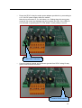
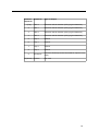
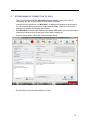
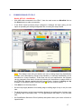
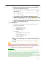
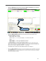
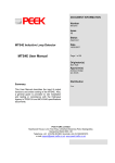
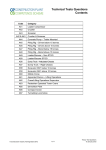
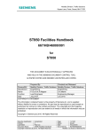
TRAINING COURSE
SP4-C Bus & SCOOT
Detector Card - Basic
Contact Details
R.T.E.M. Limited
Unit 3
Leaches Farm Business Centre
Bicester Road
Kingswoood
Aylesbury
Bucks
United Kingdom
HP18 0RF
Telephone:
+44 (0)1296 770765
Facsimile:
+44 (0)1865 451477
Web:
www.rtem.co.uk
Email:
[email protected]
SP4-C Basic Training Course
R.T.E.M © Copyright 2013
(This document may not be reproduced without the permission of R.T.E.M. Ltd)
2
Document Control
Document Number
:
TCSP4-C001
Issue Number
:
1.00
Authors
:
Paul Stroud
Document History
Issue:
1.00
Date:
01/03/2013
Description:
Release Notes:
Issue 1.00
Initial release. Basic course covering
installation, commissioning and maintenance.
Advanced course to follow.
3
COURSE CONTENTS
1. Introduction to RTEM & background to development of SP4-C
Page 5
2. Overview of SP4-C – capability & applications
Page 6
3. Suitable detector loop arrays
Page 10
4. Installation of SP4-C in a signal controller cabinet
Page 12
5. Establishing PC connection to SP4-C
Page 15
6. Commissioning of SP4-C
Page 17
7. Routine Maintenance & Fault Investigation
Page 26
8. Support
Page 27
9. Q & A
Page 28
4
1.
INTRODUCTION TO RTEM
The company was formed in 2006 with the aim of bringing the next generation of
traffic data collection technology to the marketplace. By combining expertise in loop
detection with design skills from the mobile phone industry, we have developed a
product based on the technology of today without the encumbrances of any legacy
product.
RTEM launched the SP4 loop-profiling classifier with a range of software applications
that introduce a wealth of innovative enhancements to the Traffic Data Collection
Industry. These pioneering enhancements include the first product in the world to
provide classification data from a single loop. In addition we offer classification based
on the number of axles and axle spacing from a site using a standard 2 loop
classification array.
•
•
•
•
•
Established in 2006
IS09001-2008 registered
Highly experienced staff
Products completely manufactured in UK to ensure high quality
Marketed directly to UK customers since 2009
RTEM equipment is in use for automatic traffic count and classification in 11 local
authorities across England and Scotland, as well as consultancies, private companies
and certain foreign territories.
BACKGROUND TO DEVELOPMENT OF SP4-C
The SP4's single-loop classification capability led customers to ask whether it could
be used for the collection of full classified traffic data from SCOOT loops (which have
similar characteristics to traditional traffic count loops).
Tests showed that the SP4 could indeed be used for this purpose and its
performance in congested traffic conditions allowed good quality data to be collected
where traffic classification sites would previously have been ruled out.
RTEM therefore developed the ability to replicate SCOOT output to a signal controller
to allow SP4s to be installed as temporary or permanent replacements for the original
loop detector card.
Once customers became aware that vehicles could be economically and accurately
classified from a SCOOT loop, we started to get requests to provide a bus detection
output. This was implemented, but was limited by the SP4 having a single switched
output – it was therefore not possible to provide both SCOOT and bus detection
output from the same detector.
At this stage development of the SP4-C was started, to provide multiple configurable
outputs in a format more convenient for installation in signal controllers.
Officially launched at the JCT traffic signal symposium 2012, the SP4-C is in use in 5
areas around the UK and has been installed in both Siemens and Peek controllers.
5
2.
OVERVIEW OF SP4-C – CAPABILITY & APPLICATIONS
Power indicator LED
Recording status LED
LED activation button
USB comms port
Loop activation /
SCOOT output LEDs
Selective Vehicle
Detection output LEDs
Selective Vehicle
Detection output LEDs
6
Removable memory card
Serial number & contact phone no.
Key Features:
The SP4 rack-mounted detector card builds on the proven benefits of the boxed SP4.
•
Connects to up to 4 inductive loops
•
•
Multiple units can be networked
Tolerant of a wide variance in loop specification and quality
Records vehicle-by-vehicle data (up to 53 million vehicles)
Multiple output switches for integration with external devices
Removable flash memory card
USB Engineers' interface to PC / Android tablet
Low power – battery only, solar and mains operation
GSM / GPRS telemetry options
Compatible with ADSL / Ethernet / RS485 communications
Data formats compatible with industry standard analysis packages and
UTMC databases
•
•
•
•
•
•
•
•
7
Technical Specification:
Weight:
160g
Dimensions:
“Eurocard” size to fit in 3U rack mounting
File Storage:
FAT 16 (Windows compatible)
Memory card type:
Compact Flash (CF). Size 512MB – 8GB
Voltage:
4-24v DC
Power Consumption:
100mW
Operating Temperature Range: -20oC to +70oC
Environmental Protection:
IP64
Firmware:
Flash upgradeable by user
Ports:
USB comms
RS232 comms/modem
RS485 network
Data Retrieval Methods:
Direct USB connection with PC / Tablet
Removal of CF card
GSM “dial-up” telemetry
GPRS telemetry
ADSL connection
Ethernet connection
RS485 network connection
Length Classification Accuracy: +/-3% with 95% confidence
Speed Classification Accuracy: +/-3% (typically +/-1mph)
Vehicle Type Classification
Accuracy (Euro6):
Pedal cycles: >95%
Motorbikes: >95%
Cars / Light Goods Vehicles: >98%
Cars/LGVs with trailer: >90%
Lorries: >95%
HGVs: >95%
Buses / Coaches: >95%
With 95% confidence, based on typical loop array.
8
Supported Vehicle
Classification Schemes:
DoENI5
Euro6
User Definable Class Schemes (up to 24 vehicle
types)
Switched outputs:
4 x SCOOT output (1 for each loop)
4 x SVDS output (1 for each loop)
Firmware “Apps”
Single Loop Classification
The slp firmware App is designed for the collection of fully classified vehicle data
(length, speed, class, gap) from a single inductive loop in each traffic lane. This
allows much more useful data to be obtained from legacy “volumetric” count sites or
traffic signal loops without the cost of upgrading the loop arrays. Each SP4 can
connect to up to 4 traffic lanes. Compatible with networking, SVDS, SCOOT, all
alerting & communications options.
“Traditional” Dual Loop Classification
The modsig firmware App is intended as a direct replacement for legacy speed /
classification loop detectors. Each SP4 can monitor 2 traffic lanes – expandable to 14
lanes by networking multiple units. Offers automatic switching to single loop
classification mode in the event of a loop failure, providing continuity of operation and
flexibility in scheduling repairs. Compatible with SVDS, SCOOT, incident detection
and all communications options.
Cycle Detection
The cycledet firmware App allows the detection, counting and classification of pedal
cycles in dedicated cycle lanes. Up to 4 cycle loops can be monitored by each SP4.
Compatible with SVDS, alerting and all communications options.
Networking
Up to 7 SP4 units can be networked together either at the same site or within a 4km
distance. Each SP4 can be configured separately and appropriately for the site using
any of the Apps, but is then subsequently controlled through the “master” unit which
stores all data and handles communications. This allows the flexibility to cover multilane sites without the need for specialist high-cost equipment, or to manage all the
units along a road through a single communication channel. The RS485 connection
can alternatively be used as a means of retrieving data from a single SP4.
9
3.
SUITABLE DETECTOR LOOP ARRAYS
SP4-C detectors can be used with existing SCOOT, Stop Line or Speed Detection
loops providing they are in reasonable condition and do not span more than a single
traffic lane.
MOVA loop compatibility is anticipated in the next 6 months – tests are ongoing to
fine-tune classification accuracy with these diamond-shaped loops.
If new loop arrays are to be installed, it is recommended to install 2 loops per lane (to
benefit from built-in redundancy) to the following specification:
Sites should all be installed in accordance with the specifications for Speed
Measuring Loops for All Purpose Roads laid out in MCH1540 and MCHW Vol 3
G Series drawings (copies of these docs available in pdf format from RTEM on
request).
Exceptions to this specification are as follows:
- ALL LOOPS SHOULD HAVE 4 TURNS OF CABLE.
- LOOP LENGTHS AND SEPARATION AS BELOW.
- FEEDER CABLE SHOULD BE TWISTED LOOP CABLE (WITHOUT JOINTS)
EACH PAIR HAVING 20 TWISTS/M APPLIED. THIS IS PREFERABLE TO
ARMOURED CABLE.
- MAX FEEDER CABLE RUN LENGTH 250M.
- WHERE A WIRELESS LINK IS TO BE USED BETWEEN THE LOOP AND
CONTROL CABINET, DETECTION EQUIPMENT MUST BE LOCATED
BETWEEN THE LOOP ARRAY AND WIRELESS LINK. LOOP FEEDER
CABLE SHOULD BE TERMINATED TO THIS POINT AND PROVISION
MADE FOR HOUSING & POWERING THE DETECTION EQUIPMENT.
- IF LOOPS ARE TO BE USED FOR BUS PRIORITY OR SIGN ACTIVATION
RECOMMENDED LOCATION OF LOOP ARRAY IS BETWEEN 50M AND
130M UPSTREAM OF SIGNALS / SIGNS, BUT IN ANY CASE SHOULD BE
UPSTREAM OF MAXIMUM QUEUE EXTENT. IF THESE CRITERIA CAN'T
BE MET, REFER TO RTEM FOR ADVICE / SITE INSPECTION.
10
SETTING LOOP LENGTH & LOOP SEPARATION
EXAMPLE 1 – FREE-FLOWING TRAFFIC, ALL SPEEDS
CABINET
----- 2M -----
----- 2M -----
----- 2M -----
EXAMPLE 2 – SITES WITH CONGESTION & AVERAGE SPEED < 50MPH
CABINET
----- 1M -----
----- 1M -----
----- 1M -----
11
4.
INSTALLATION OF SP4-C IN A SIGNAL CONTROL CABINET
•
Insert the card in an empty slot without a back-plane. (At present, we have to
maintain compatibility with all controller types and therefore have screw
connectors on the back of the detector card, rather than connectors for
controller back-planes).
•
Plug the Loop Cable supplied with the SP4-C into the 8-way orange connector
in the back of the SP4-C. Connect the other ends of the cable directly to the
loop feeder cables where they are terminated into the cabinet.
8-way loop cable connector (2 per loop)
Colour coding for Loop Cable:
Loop 1
Orange
Loop 2
Yellow
Loop 3
Brown
Loop 4
Red
12
•
Power the SP4-C using the mains power adapter provided or by connecting to
a 12 / 24v DC power supply within the cabinet.
Note the top connector is -ve, the bottom +ve. Getting these the wrong way
round will not cause any damage, but will not power the SP4. If the LEDs do
not illuminate on pressing the CF CTRL button, check polarity is correct.
DC Power Connector
•
Connect required outputs and a common ground from SP4-C using 10-way
green screw-terminal connector.
Detector Card Outputs
13
Terminal / Output for:
Output No.
Type of Output:
1 (Top)
Lane 2
Selective vehicle detection (SVD) (eg bus detection)
2
Lane 1
Selective vehicle detection (SVD) (eg bus detection)
3
Lane 4
Selective vehicle detection (SVD) (eg bus detection)
4
Lane 3
Selective vehicle detection (SVD) (eg bus detection)
5
Loop 2
SCOOT
6
Loop 1
SCOOT
7
Loop 4
SCOOT
8
Loop 3
SCOOT
9
All outputs
Common Ground (must be connected for outputs 1-8 to
work)
10 (Bottom) Positive
Not used
14
5.
ESTABLISHING PC CONNECTION TO SP4-C
The PC should have RTEM's MicroDial software installed, along with Java (if
necessary) and the CP210x driver for USB communications.
License files are required to run MicroDial – a dialogue will appear on first trying to
run the software with instructions to obtain these licenses. There is no up-front or
ongoing cost relating to licensing the software.
•
Run MicroDial and enter login root and password 1234 (other user accounts can be
created by ticking the box on the login screen before logging in).
•
From the Setup menu, select PC Communication Setup.
•
Set the Direct Connection Baud Rate to 57600
15
•
Set the Direct Connection Com Port to Com1-10 based on the USB port you will
usually connect with. Note that if you connect a powered SP4 you should be able to
identify the COM port number from the Windows Device Manager
Look under Ports (WinXP / Win7)
for an entry like this
•
Set the database path to a convenient location (you can have multiple databases).
•
Save & Close
•
Click on Direct button to communicate with the SP4-C
Note: If you vary the USB port used, MicroDial will report a failure to connect and will
offer the option of running auto setup to scan through ports 1 – 10 to try to find an
SP4. If this is unsuccessful, you will either need to revert to the normal USB port or
change the settings as described above.
16
6.
COMMISSIONING OF SP4-C
BASIC SET-UP - UNIVERSAL
•
With USB cable connected to the SP4-C, from the main screen on MicroDial click on
the Direct button to make a connection.
•
If the SP4-C hasn't previously been configured, a dialogue will open giving you the
option of uploading an existing configuration file or running the setup wizard.
Note: This dialogue also tells you whether the unit is running single-loop classification
firmware (unit is described as “Single Loop Classifier”) or dual-loop classification (unit is
described as “4-Loop Classifier”). If this does not suit your requirements, the firmware
can be changed in less than 3 minutes by following the instructions on pages 36-38 of
the RTEM User Manual supplied with these course notes. Versions of modsig and slp
firmware for use with the SP4-C have the suffix ev after the version number.
•
Click Next to run the setup wizard.
•
Set the loop length (distance from leading edge to trailing edge of loop in cm) for each
lane.
•
For dual-loop arrays, set the loop separation (distance from trailing edge of primary loop
to leading edge of secondary loop – i.e. the gap between the loops – in cm) for each
lane.
•
Set Classification Scheme to Euro6 (default) and speed units to your choice of metric or
imperial units.
17
•
Click Next
•
Enter an appropriate site name and site number (site number is max 4 digits).
•
Click Next
•
Chose a format for data storage. The log option will store data in a text file format, which
can easily be viewed on site or in the office using Notepad or similar. The binary option
will create a more compressed data file which cannot be read before processing into the
MicroDial database, but allows quicker transmission over GSM telemetry links.
18
•
Click Next
•
Select the type of modem connected (if appropriate)
•
Click Next
•
Press Do It to save the configuration to the SP4-C and your PC
•
You will then be prompted to run a Report Wizard to define how raw data is processed
when downloaded from the site in future. This can be run at any time from the Reports
menu.
19
ADVANCED SET-UP - OPTIMIZING SINGLE LOOP CLASSIFICATION ACCURACY
On most roads, the SP4 will classify accurately from a single loop in each lane using
the default settings. There are however a few quick adjustments you can make, which
will ensure the system is working to the best of its potential.
Recommended for:
•
All sites with a single loop in each traffic lane
•
Sites with 2 loops in each lane where the user has concerns that one or more
loops may fail
Firmwares this applies to:
•
Standard factory installed “modsig” firmware, which will classify from a single
loop in 1 or 2 lanes
•
“slp” firmware, which will classify from a single loop in up to 4 lanes
•
“scoot” firmware, used for classifying from a single traffic signal loop
Best time to carry out this operation:
•
As part of initial commissioning of equipment (only adds approx 5 mins to the
procedure)
•
Parameters can be changed at any time via remote (telemetry) connection,
but best carried out with direct connection on site and with live traffic passing
over the loops.
1. Whilst connected to the SP4, from MicroDial main screen, click on “Live”
button from toolbar at top of window.
2. The Live screen will display and records will appear for all traffic passing over
the loops. Pay particular attention to the “Height” column and make a note of
the average reading in this column for standard cars (i.e. not 4x4) in each
traffic lane. If the site is busy, you may find the lane filter tick-boxes on the
right-hand side of the screen useful to monitor 1 lane at a time.
3. Also make a note of the average Height readings for motorbikes (passing over
the loop, not clipping the edge) and HGVs in each lane if the mix of traffic on
site permits this in a reasonable time scale. (If not, please see HELP! below).
INFORMATION:
The “Height” measurement on the Live view screen refers to the height of the
vehicle's chassis. The figure does not relate to any specific unit (mm, cm or
similar), but provides a relative scale which is used by the SP4 in verifying the
vehicle classification derived from the chassis profile.
Because the signals created by loops can vary significantly according to the
quality of cable used, size of loop, number of turns of cable, installation depth
and age, the SP4 can be calibrated according to the readings actually being
obtained on site. Unfortunately, because of all these variables and the need to
have a visual check on passing vehicles, it is not possible at present to fully
automate this process.
The remainder of this procedure can be carried out either from the “Site Data” screen
or the “Advanced” (“Signatures” in V2.6 Release 6 or older) screen of MicroDial.
4. Site Data screen:
20
•
Ensure the “More details” tick-box is ticked, then click on the “Req”
button to retrieve settings from the SP4.
•
A scroll bar will appear on the right. Scroll down (or click on any setting
and arrow down) to display the “BikeRatio”, “Car Ratio” and “Speed
Limit” settings.
•
If the car height readings you took differ significantly from the default
settings, double click on the setting for the appropriate lane, change
the value and click “Modify”.
•
If you were able to monitor motorbike height readings, adjust the
“BikeRatio” settings in the same way. If not, see HELP! below. then as
a rule of thumb, the “BikeRatio” should be set to approximately 7 x the
“Car Ratio” or 3 x the average HGV height reading.
•
Adjust the “Speed Limit” setting to reflect the posted speed limit, or the
average speed if significantly different.
4. Advanced screen:
•
In the “Enter Commands” box type in the new settings as follows:
•
“modsig” or “scoot” firmware
•
•
CAR_RATIO <L1> <L2>
•
BIKE_RATIO <L1> <L2>
•
SPEED_LIMIT XX
“slp” firmware
•
CAR_RATIO <L1> <L2> <L3> <L4>
•
BIKE_RATIO12 <L1> <L2>
•
BIKE_RATIO34 <L3> <L4>
•
SPEED_LIMIT XX
Where <L1> is the desired value for lane 1 and XX is the new speed limit
setting.
If you were unable to monitor motorbike height readings, see HELP!
below.
HELP!
If the site has insufficient flow of motorbikes to allow you to monitor their height
readings in a reasonable time scale (as is commonly the case), apply the following
rule of thumb:
BIKE_RATIO = 7 x CAR_RATIO or 3 x HGV height reading
INFORMATION:
The Speed Limit setting is used as a further check on vehicle classification. For
example, a bus or HGV is unlikely to be travelling well in excess of the posted limit.
This setting is not used for reporting on the number of vehicles exceeding the speed
limit or for triggering external devices, such as speed activated signs.
It is therefore sensible to adjust this setting to the average speed of vehicles at the site if
this is significantly different to the posted speed limit. Doing so will have no detrimental
effect on any other aspect of the SP4's operation or its data.
21
ADVANCED SET-UP – CONFIGURING SCOOT OUTPUT(S)
The SCOOT output for each loop is configured automatically within the firmware and will
start working immediately the SP4-C is powered up. For the majority of sites no
configuration is necessary.
If, when monitoring the input to the controller, you see the SCOOT loop polarity is
reversed (i.e. loop shows 1 when no vehicle is present and 0 when a vehicle is over the
loop) this can be remedied through the MicroDial Advanced screen using the
SELECT_ONSTATE command (see User Manual section 9.3.97, page 90 for full
details).
22
ADVANCED SET-UP – CONFIGURING SELECTIVE VEHICLE DETECTION
OUTPUT(S) FOR BUS DETECTION
•
Go to the Advanced section in MicroDial.
Advanced section
23
•
Select the Manual tab, then tick the check-box Select commands which populates
the drop-down box with all the relevant commands.
Manual tab
Drop-down command box
•
Select the BUS_LANE command from the drop-down list and amend it in the
command string box as follows:
BUS_LANE <lane> <state>
Where <lane> = 1, 2, 3 or 4 and <state> = 1 for ON or 2 for OFF
Thus:
BUS_LANE 3 1
turns on bus detection for lane 3
BUS_LANE 1 0
turns off bus detection for lane 1
Turning bus detection on will create a positive switch output for 500 milliseconds
when a bus is detected, regardless of direction of travel. Any of these elements can
be amended using the appropriate SELECT_ commands.
Full details can be found in the User Manual section 9.3.9, page 51.
•
Entering HELP_SELECT provides on-screen information about all SVDS commands,
while SELECT gives current settings and is a useful check to confirm your changes
have been retained correctly.
24
•
To create an artificial output trigger for testing purposes, enter the following
command:
TEST_6 <n>
Where <n> is the output number from the table on page 14.
This will create a permanent output (not 500 milliseconds) until cancelled with the
command:
TEST_5 <n>
25
7.
ROUTINE MAINTENANCE & FAULT INVESTIGATION
The SP4-C requires no more routine maintenance than any other detector card. During
routine checks on the controller, the following is recommended:
•
Press the CF CTRL button to illuminate the LEDs on the SP4-C front panel.
•
Monitor the LED activation to check vehicle presence detection (Loop O/P
LEDs) and bus detection (Class O/P LEDs).
•
Connect PC to SP4-C to monitor LIVE view if any concerns.
•
Retrieve traffic data from CF card if required.
The SP4-C has no user-serviceable parts.
In the event of a loop fault, the SCOOT output(s) will default to ON and the bus
detection outputs will default to OFF.
In rare circumstances, underground services or other causes of electromagnetic
disturbance can cause interference to the signals from detector loops. If this is
sufficiently severe, it may impact on the quality of vehicle classification which can be
achieved.
It is very difficult to anticipate which sites may be affected by this phenomenon. It is
possible to vary the frequencies at which each loop is monitored and filter out
interference to a degree. Ultimately, if interference cannot be overcome, it may be
necessary to re-site detector loops or consider using alternative bus detection methods
at affected locations.
If you are not achieving acceptable levels of classification (or for advice on any other
suspected fault), please see the support notes in the following section.
26
8.
SUPPORT
RTEM provides 1st and 2nd line support for the SP4-C.
1st Line Support
Available Monday – Friday between 09:00 & 17:00hrs
(excluding Bank Holidays)
Tel: 01296 770765 (Office)
Mobile: 07918 704643 (Anup)
Mobile: 07780 333244 (Paul)
Email: [email protected]
2nd Line Support
If we are unable to diagnose or resolve a problem through telephone or email
support, we will agree an appropriate course of action with you, which could
involve:
•
monitoring the site remotely (if possible)
•
sending an RTEM engineer to site
•
requesting the return of the SP4-C for testing
•
dispatching a temporary replacement SP4-C unit or component.
All SP4 units benefit from an initial 2 year warranty, extendable at the client's
discretion. Whilst under warranty, any site visits and/or work necessary to resolve
suspected faults will be carried out free of charge.
Outside of the warranty period, charges for site attendance may apply. You will be
informed in advance of incurring any charge if this is the case. Typical charges are
£250 for ½ day site attendance and £450 for a full day.
Bespoke support arrangements are in place for some customers. Please enquire
when requesting support to ascertain what arrangements are in place for the
equipment concerned.
27
Notes:
28
Notes:
29