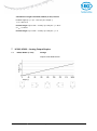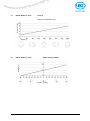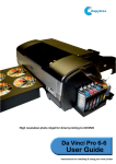
1
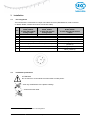
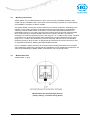
User manual Inclinometer with Analog-RS232-Interface IK360, IK360L IK360, IK360L-RS232 x Date: 10.02.2015 Page 1 of 22 Art.no. 86152 Mod. Status 52/15 Table of content 1 GENERAL SAFETY ADVICE .......................................................................................................... 3 2 INTRODUCTION .............................................................................................................................. 3 2.1 2.2 2.3 3 INSTALLATION ............................................................................................................................... 5 3.1 3.2 3.3 3.4 4 PIN ASSIGNMENT .......................................................................................................................... 5 INSTALLATION PRECAUTIONS ......................................................................................................... 5 MOUNTING INSTRUCTIONS ............................................................................................................ 6 MEASUREMENT AXIS ..................................................................................................................... 6 IK360, IK360L SOFTWARE CONFIGURATION ............................................................................. 7 4.1 4.2 4.3 5 IK360, IK360L............................................................................................................................. 3 ANALOG INTERFACE...................................................................................................................... 4 IK360, IK360L ANALOG ............................................................................................................... 4 IMPORTANT FACTORY SETTINGS .................................................................................................... 7 MODES OF OPERATION ................................................................................................................. 7 PROGRAMMABLE PARAMETERS ..................................................................................................... 8 RS232 DIGITAL INTERFACE – SETUP AND PROGRAMMING ................................................... 8 5.1 HARDWARE SETUP ....................................................................................................................... 9 5.1.1 Accessories Required ........................................................................................................ 9 5.1.2 RS232 Communicarion – Pin Configuration ...................................................................... 9 5.1.3 Wiring & Connection .......................................................................................................... 9 5.1.4 Connection Setup ............................................................................................................ 10 5.2 SOFTWARE COMMUNICATION SETUP ...........................................................................................10 5.3 BOOT-UP MESSAGE REPRESENTATION .......................................................................................12 5.4 IK360, IK360L OUTPUT – PROGRAMMING INDEX .........................................................................12 5.4.1 Table 1: Commands in Configuration Mode .................................................................... 13 5.4.2 Table 2: Code Transmission Rates ................................................................................. 14 5.4.3 Table 3: Baud rates ......................................................................................................... 14 5.4.4 Preset/Direction and Teach-in Mode ............................................................................... 14 5.4.5 Teach-In mode (teach 1) ................................................................................................. 15 5.4.6 Analog Inputs (SET1 and SET2) ..................................................................................... 15 5.4.7 Preset ............................................................................................................................... 17 5.4.8 Invert Direction ................................................................................................................. 17 5.4.9 Scaling of Output ............................................................................................................. 17 6 ANALOG INTERFACE .................................................................................................................. 18 6.1 OUTPUT TYPES ..........................................................................................................................18 6.1.1 IK360, IK360L - Voltage ................................................................................................... 18 6.1.2 IK360, IK360L – Current .................................................................................................. 19 7 IK360, IK360L - ANALOG OUTPUT GRAPHS ............................................................................. 20 7.1 7.2 7.3 7.4 7.5 7.6 IK360, IK360L (1 AXIS) IK360, IK360L (1 AXIS) IK360, IK360L (2 AXIS) IK360, IK360L (2 AXIS) IK360, IK360L (2 AXIS) IK360, IK360L (2 AXIS) IK360, IK360L-RS232 VOLTAGE ..............................................................................................20 CURRENT..............................................................................................21 X-AXIS VOLTAGE OUTPUT.....................................................................21 Y-AXIS VOLTAGE OUTPUT.....................................................................22 X-AXIS CURRENT OUTPUT ....................................................................22 Y-AXIS CURRENT OUTPUT ....................................................................22 x Date: 10.02.2015 Page 2 of 22 Art.no. 86152 Mod. Status 52/15 1 General Safety Advice Read these instructions carefully and have a look at the equipment to become familiar with the device before trying to install, operate or maintain it. The following special messages may appear throughout this documentation & on the equipment to warn of potential hazards or to call attention towards information that clarifies / simplifies a procedure. The addition of this symbol to a Danger or Warning safety label indicates that an electrical hazard exists, which will result in personal injury, if the instructions are not followed. This is the safety alert symbol. It is used for alerting, in case of potential personal injury or hazards. Obey all safety messages that follow this symbol to avoid possible injury or death. Please Note Electrical equipment should be serviced only by qualified personnel. No responsibility is assumed by SIKO for any consequences arising out of the use of this material. This document is not intended as an instruction manual for untrained persons. About this manual This user manual explains how to install and configure the IK360, IK360L inclinometer with a Analog (Voltage or Current) and RS232 interface by illustrations. 2 2.1 Introduction IK360, IK360L IK360, IK360L inclinometers sense and measure the angle of tilt (Inclination/Slope/Elevation) of an object with respect to the force of gravity. The angle is measured with the relative change in electrical capacitance. The basic principle behind this IK360, IK360L inclinometer is a Micro-Electro-Mechanical Systems (MEMS) sensor cell, that is embedded to a fully molded ASIC. A simplified version of the sensor consists of two electrodes, one is fixed, and the other is flexible (connected with spring elements). When the inclinometer is parallel to the surface of measurement, a corresponding capacitance is measured. If the sensor is tilted, the flexible electrode will change its position relative to the fixed electrode. This results in a change of the capacitance between the two electrodes, which is measured by the sensor cell. The change of the capacitance is converted to a corresponding inclination value. IK360, IK360L-RS232 x Date: 10.02.2015 Page 3 of 22 Art.no. 86152 Mod. Status 52/15 Absolute inclinometers identify all the points of a movement by means of an unambiguous signal. Due to their capacity to give clear and exact values to all inclinations positions, inclinometers have become one of the interesting alternatives to singleturn absolute (and incremental) encoders and a link between the mechanical and control systems. 2.2 Analog interface The analog interface is one of the most common and simplest of the interfaces. It is compatible from simple multimeters to complex control systems and PLCs. An analog signal is a continuous signal which is analogous i. e. comparable to another time varying signal. In our case the variation of current or voltage signal from IK360, IK360L is analogous to the variation of measured position. In IK360, IK360L, the position related output from MEMS based capacitance transducer measurement is converted to its analogous current or voltage signals with suitable electronics. An analog signal virtually has infinite resolution. In practice an analog signal is always subjected to noise and a finite slew rate. Therefore, analog systems are subject to limitations in resolution and bandwidth. Noise and unwanted variation in signals can create losses upon transmission and retransmission over long distances and for long time. Electrically, these losses can be reduced by shielding, good connections and several cable types. 2.3 IK360, IK360L Analog The IK360, IK360L Analog inclinometer is a simple, compact and a very low cost inclination measurement device capable of measuring precise absolute position in single axis. It is compatible to almost all the analog measurement devices and includes a RS232 digital interface too. This RS232 interface can be used either to read the corressponding position output or for configuring the IK360, IK360L according to the need of the application. Electrically, IK360, IK360L consists of a highly integrated circuit in SMD technology, temperature compensation, active linearization and the only variation is the analog interface. Customized scaling of analog output is also possible. Electrically, like all other IK360, IK360L variants it consists of a highly integrated circuit in SMD technology, temperature compensation, active linearization and the only variation is the analog interface. Customized scaling of analog output is also possible. It is protected against polarity inversion and over voltage peak protection. In addition to that, the fully molded plastic housing provides an high resistance to shock/vibration and environmental protection of up to IP69K, when used with appropriate connectors. IK360, IK360L-RS232 x Date: 10.02.2015 Page 4 of 22 Art.no. 86152 Mod. Status 52/15 3 3.1 Installation Pin assignment The inclinometer is connected via a 8 pin round M12 connector (Standard M12, male connector on IK360, IK360L, female connector at connection cable). 1 2 3 4 5 6 Description for Description for IK360, IK360L IK360, IK360L (1 axis) with voltage (1 axis) with current analog output analog output 10-30 V DC 12-30 V DC RxD (RS232 Receive) TxD (RS232 Transmit) Ground Z-Axis Output U/I 1 Analog input Preset or SET1 (Teach-in) 7 8 Pin do not connect 1 Analog input Inverse Direction or SET2 (Teach-in) Pin 3.2 Description für IK360, IK360L (2 axis) with current analog output 12-30 V DC RxD (RS232 Receive) TxD (RS232 Transmit) Ground X-Axis Output U/I 1 Analog input Preset or SET1 (Teach-in) Y-Axis Output U/I 1 Analog input Inverse Direction or SET2 (Teach-in) Installation precautions ATTENTION! Do not remove or mount while the inclinometer is under power! Avert any modifications to the plastic molding! Avoid mechanical load! 1 The function of the analog inputs depends on the configuration. IK360, IK360L-RS232 x Date: 10.02.2015 Page 5 of 22 Art.no. 86152 Mod. Status 52/15 3.3 Mounting instructions IK360, IK360L is a pre-calibrated device, which can be put into immediate operation, upon simple and easy installation with a three point mount and setting of preset. Its compact design and installation "anywhere" makes it versatile. The IK360, IK360L inclinometer can be mounted in any number of fashions, depending on the situation. The mounting surface must be plane and free of dust and grease. It is absolutely necessary, that the IK360, IK360L inclinometer is connected to potential equalization in a workmanlike manner. For mounting we recommend cheese head screws with metrical thread M4 or UNC bolts #6 for the best possible and secure mounting. Use all the 3 screws for mounting, but restrict the tightening torque in the range of 1.5 – 2.5 Nm for the screws. The M12 connectors are to be perfectly aligned and screwed till the end with a tightening torque in the range of 0.4 – 0.6 Nm. Use all the three screws for mounting and also note to use the same tightening torque for all the screws. An appropriate and well secured counter connector is also an important constraint for attaining the stated IP69K protection. Prior to installation, please check for all connection and mounting instructions to be complied with. Please also observe the general rules and regulations on low voltage technical devices, for safety and sustainability of IK360, IK360L Inclinometers over long period of time. 3.4 Measurement axis IK360, IK360L (1 axis) Measurement axis and mid angle position (factory setting ~ connector facing down) IK360, IK360L-RS232 x Date: 10.02.2015 Page 6 of 22 Art.no. 86152 Mod. Status 52/15 IK360, IK360L (2 axis) 4 IK360, IK360L Software Configuration The IK360, IK360L - Analog Inclinometer is a very flexible device and can be easily configured using the RS232 interface. 4.1 Important factory settings Description Operational Mode Resolution Output Transmission Rate Baud Rate Moving Average Filter Angle Offset Measurement Direction Configuration Mode Value Continuous Mode 0.01° - IK360 0.05° - IK360L 100 ms 9600 bd 64 0 Clockwise Preset / Direction Mode Note: The factory settings should be noted carefully upon installation. Few of the parameters have to be re-programmed in order to make the IK360, IK360L inclinometers compatible with the measurement device, or optimize the measurement. 4.2 Modes of Operation Measurement Mode Measurement mode of an IK360, IK360L is the free running operational output mode, in which the position value is sent cyclically (according to the output transmission rate) using the RS232 interface. IK360, IK360L-RS232 x Date: 10.02.2015 Page 7 of 22 Art.no. 86152 Mod. Status 52/15 Configuration Mode This mode is primarily used for modifying configurations and the settings of IK360, IK360L using RS232 Interface. In this mode, the position value is transmitted only upon request and is active until a power cycle, software reset or the IK360, IK360L is switched to measurement mode. All settings saved in this level are stored in the EEPROM and permanently available also after power cycle. There are two additional configurations for the teach-in functionalities which can be configured in this mode: Preset / Direction Mode This is the default mode. In this mode, we can use an analog input for setting to zero position. The default direction setting is clockwise. Analog input for inversing direction is not available until setup to do so in RS232. - Teach-In Mode (Scaling) This is used for scaling of the analog output over a desired range, using RS232 or Analog inputs. - 4.3 Programmable parameters The parameters/ settings of the IK360, IK360L can be re-configured using RS232 interface. Additionally few of these functionalities are also available through Analog inputs SET1 and SET2. Configuration Mode Baud rate Output Transmission Rate Moving Average Filter Preset Value Measurement Direction Analog Output Scaling 5 IK360, IK360L can be switched between Preset/Direction Mode and Teach-In Mode The Baud rate can be programmed to lie between ranges of 2400 bps and 115200 bps The transmission rate of angular values can be adjusted to lie between 62.5 ms and 10 seconds per value Used to calculate the output position value as an average over last N values where N varies from n 1 to 256 measurements (where N = 2 , n = 0, 1, 2, 3 …) The current position value is set to the mid angle and Zero position by the parameter preset. The direction of measurement can be inversed according to the measurement requirement The analog output (4-20 mA / 0 V-10 V ) can be scaled to the required measurement range The default ranges are 0° to 359.99° Adjustable via RS232 RS232 RS232 RS232 RS232 and Analog 2 input SET1 RS232 and Analog 2 input SET2 RS232 and Analog 3 inputs SET1 and SET2 RS232 Digital Interface – Setup and Programming The RS232 interface of IK360, IK360L gives flexibility to the Inclinometer by providing easily accessible direct positional values and a simple interface for setup and configuration. 2 3 only in Preset/Direction mode only in Teach-In mode IK360, IK360L-RS232 x Date: 10.02.2015 Page 8 of 22 Art.no. 86152 Mod. Status 52/15 5.1 Hardware Setup 5.1.1 Accessories Required IK360 Inclinometer 8- Wire open ended connection cable with M12 8-pin female connector D-Sub9 Female Connector 5.1.2 RS232 Communicarion – Pin Configuration Pin 2 3 5 5.1.3 Preparation of IK360, IK360L RS232 Communication Cable Description Receive data Transmit data Common Ground Wiring & Connection IK360, IK360L-RS232 x Date: 10.02.2015 Page 9 of 22 Art.no. 86152 Mod. Status 52/15 5.1.4 Connection Setup IK360, IK360L Analog 5.2 -> M12 Connector -> RS232 Connector -> PC RS232 Port Software Communication Setup Once the hardware is connected, the RS232 interface communication has to be setup using HyperTerminal or any other terminal programming client software. Communication with the sensor is done through a standardized RS232 interface. Data transmission is effected in duplex mode. RS232 Interface Parameters are: Baud Rate: 9600 bd Data Bits: 8 Bits Parity: Even Parity Stop Bits: 1 Bit Flow Control: None Step 1: Open the executable file of PuTTY - A Telnet/SSH client freeware. Please click on Serial in Connection type and then type in the appropriate COM port in the Serial line column and the current Baud rate in the Speed dialog box. Then select, SSH -> Serial to setup the parameters for interface communication. IK360, IK360L-RS232 x Date: 10.02.2015 Page 10 of 22 Art.no. 86152 Mod. Status 52/15 Step 2: The appropriate parameters for the RS232 interface communication and please click on Open to create a new terminal program for IK360, IK360L RS232 interface communication. COM Port Baud Rate Data Bits Stop Bits Parity Flow Control Power Off – Power On for getting a boot-up message on startup. IK360, IK360L-RS232 x Date: 10.02.2015 Page 11 of 22 Art.no. 86152 Mod. Status 52/15 5.3 Boot-Up Message Representation In the bootup messages are most important features: IK360, IK360L (1 axis) Company IK360 Typ SW and HW Versions Baud Rate, Output Rate, Filter Parameter, Preset Position Serial Number IK360, IK360L (2 axis) Company IK360 Typ SW and HW Versions Baud Rate, Output Rate, Filter Parameter, Preset Position Serial Number 5.4 IK360, IK360L Output – Programming Index The following table is of the character and its corresponding decimal/ hexadecimal equivalents to assist a user in the output programming. IK360, IK360L (1 axis) CHAR ASCII DEC HEX D0 X D1 X D2 X D3 . 46 Variable Numerical Values 0x2e D4 D5 X X Variable Numerical Values D6 CR 13 D7 LF 10 0x0d 0x0a IK360, IK360L (1 axis) Output Display: <D0……….D5 D6 D7> <CR> <LF> is a program analogy to indicate end of current line and start of a new line in a program. IK360, IK360L (2 axis) CHAR ASCII D0 X D1 = DEC 88 61 HEX 0x58 0x3d CHAR ASCII D9 Y D10 = DEC 89 61 HEX 0x59 0x3d IK360, IK360L-RS232 x Date: 10.02.2015 D2 +(+:43) (-:45) (+:0x2b) (-:0x2d) D11 +(+:43) (-:45) (+:0x2b) (-:0x2d) D3 x D4 x Variable Numerical Value D12 x D13 x Variable Numerical Value Page 12 of 22 D5 . 46 0x2e D14 . 46 0x2e Art.no. 86152 D6 x D7 x Variable Numerical Value D15 x D16 x Variable Numerical Value D8 ; 59 0x3b D17 CR D18 LF 13 10 0x0d 0x0a Mod. Status 52/15 IK360, IK360L (2 axis) Output Display: <D0……….D16 D17 D18> <CR> <LF> is a program analogy to indicate end of current line and start of a new line in a program. 5.4.1 Table 1: Commands in Configuration Mode General Instructions Enter configuration mode Leave configuration mode List all commands and their descriptions 4 Software Reset Report the identity and versions (Bootup Message) Parameter Info 5 Set output rate Read current position value 6 Set new baud rate 7 Set new moving average filter value 8 Filter deactivate Restore factory settings (requires save) 9 Save settings to EEPROM 10 Mode configuration Set origin at current position (Preset) Reset the origin to factory default position Teach-in Mode Commands Set maximum V/I at current position Reset the maximum V/I to factory default position Preset/Direction Mode Commands Invert the direction of measurement To the Sensor <CR> exit<CR> help<CR> Hex Value 0Dh 65h 78h 69h 74h 0Dh 68h 65h 6Ch 70h 0Dh *rst<CR> *idn<CR> 2Ah 72h 73h 74h 0Dh 2Ah 69h 64h 6Eh 0Dh info<CR> period<SP>parameter<CR> read<CR> baud<SP>parameter<CR> filter<SP>parameter<CR> filter<SP>parameter<CR> restore<CR> 69h 6Eh 66h 6Fh 0Dh 70h 65h 72h 69h 6Fh 64h 0Dh 72h 65h 61h 64h 0Dh 62h61h75h64h20h ..h 0Dh 66h 69h 6Ch 74h 65h 72h 20h .. h 0Dh 66h 69h 6Ch 74h 65h 72h 20h .. h 0Dh 72h 65h 73h 74h 6Fh 72h 65h 0Dh save<CR> teach<SP>0<CR> Preset / Direction Mode teach<SP>1<CR> Teach-in Mode 11 setorg <CR> clrorg<CR> 73h 61h 76h 65h 0Dh 74h 65h 61h 63h 68h 20h 00h 0Dh setmax<CR> clrmax<CR> 73h 65h 74h 6Dh 61h 78h 0Dh 63h 6Ch 72h 6Dh 61h 78h 0Dh compl<SP>parameter<CR> 63h 6Fh 6Dh 70h 6Ch 20h 0Dh 74h 65h 61h 63h 68h 20h 01h 0Dh 73h 65h 74h 6Fh 72h 67h 0Dh 63h 6Ch 72h 6Fh 72h 67h 0Dh <CR> = cariage return <SP> = Space 4 After reset, the IK360, IK360L reboots in the measurement mode giving a startup/ boot-up message. See Table 2 for defined code transmission rates. 6 See Table 3 for defined baud rates. . A reset of the baud rate to the default value is not possible. 7 The Moving Average Filter length accepts only 2n values. E. g. 4, 8, 16, 32.. etc. and the max. length is 256. If the input number isn’t a 2n number, the next lower 2n number will be taken. E. g. input = 14 will be rounded to 8, Input =18 will be rounded to 16, etc… 8 With 0 or 1 the filter is disabled. 9 In case of changing the baud rate, the new baud rate will be active direct after a <CR>, a “save” command is not required. 10 Only sensors with version 1.86 software will have teach-in functionality. Refer to bootup message for version. 11 Setorg is used for both setting the preset and scaling in both teach-in and Preset/direction modes. 5 IK360, IK360L-RS232 x Date: 10.02.2015 Page 13 of 22 Art.no. 86152 Mod. Status 52/15 5.4.2 Table 2: Code Transmission Rates Input Character to Sensor 1 2 3 4 5 6 7 5.4.3 Output Transmission Rate (in ms) 62.5 12 100 200 500 1000 5000 10000 Table 3: Baud rates Input Character to Sensor 0 1 2 3 4 5 6 5.4.4 Baud rate (in bd) 2400 4800 12 9600 19200 38400 57600 115200 Preset/Direction and Teach-in Mode Preset/ Direction Mode (teach 0) The Preset/Direction mode is the default mode in which the IK360, IK360L operates. In this mode the user can set the origin of measurement (0° Reference Angle) at the current point and can also change the direction of measurement. The changes done in the RS232 mode also gets reflected in the analog output. Preset: Set Origin at current Position (setorg) The "setorg" command is used to set the origin (0° reference) to the current position. The analog output is also reset to read either 4 mA or 0 V according to the analog interface in use. Reset the origin to factory default (clrorg) The origin position can be reset to factory default position by using this command. The analog output is also reset to show the factory default output. Invert the direction of measurement (compl) The "compl" function is used to specify the direction of measurement to either Standard or Inverted according to the user’s requirement. The default setting is clockwise (IK360, IK360L). The analog input SET2 can be used for this function only if compl is set to "2". 12 Default Factory settings IK360, IK360L-RS232 x Date: 10.02.2015 Page 14 of 22 Art.no. 86152 Mod. Status 52/15 Compl Configuration – RS232 SET2 Analog Input* 0 – Clockwise only 1 – Counter clockwise only 2 – SET 2 Activate 5.4.5 L H L H L H Counting direction of IK360, IK360L No Change with Analog Input No Change with Analog Input Clockwise / Standard Counter clockwise / Inverted Teach-In mode (teach 1) This is the mode used for scaling the IK360, IK360L output as per the users’ requirement. The user can set the range of measurement and the IK360, IK360L analog output is scaled accordingly. The range of measurement is defined to lie within the origin and maximum angle positions, which then corresponds to the analog output scaling. The sequence SET1 and then SET2 must be observed! Important: The maximum angle set in this mode will not affect the RS232 position output. This scaling only affects the analog output. The execution of this "setmax" is immediately reflected in the analog output. The analog output at the setpoint is either 20 mA (IK360+I; IK360L+I) or 10 V (IK360+U; IK360L+U) once the execution is complete. The execution of "clrmax" function clears the previous scaling done by the user and resets the analog output to the factory default values. Important Points for programming: The use of preset in the digital interface will affect the analog output too. When using both the interfaces simultaneously take appropriate pre-cautions. Be carful not to mix up the commands für the RS232 teach-in modes. If in doubt, use the restore command and reconfigure sensor. The configurations/ scaling set in teach 1 mode is not reflected in teach 0 mode. Errors When parameters are defined beyond the programmable limits then the IK360, IK360L gives an error "E" output. 5.4.6 Analog Inputs (SET1 and SET2) The inclination sensors are designed to include 3 features through analog inputs SET1 and SET2. Preset of origin – 0° Reference for measurement Inversion of measurement direction Output scaling according to the set measurement range IK360, IK360L-RS232 x Date: 10.02.2015 Page 15 of 22 Art.no. 86152 Mod. Status 52/15 The IK360, IK360L has two configuration modes for the abov functionalities: Preset/Direction mode: Configuration for setting the new origin and direction of measurement Teach-In Mode: Scaling of output according to user's measurement range. The modes can be changed using the RS232 interface. By default, the IK360, IK360L sensor is in the Preset/Direction Mode, with the option of inversing direction with an analog input only if configured to do so in RS232. The IK360, IK360L has two analog inputs, SET1 and SET2 which can be used to configure in the IK360, IK360L. To trigger/activate these functionalities (e. g. a Preset): The user must apply a positive voltage (5 V – 30 V, Rin > 110 KΩ) on the SET1/SET2 input. When a high edge is recognized a timer starts. The voltage must be held at least 100 ms if the voltage has been held less than 100 ms, the timer will be reset. The voltage must be released for postion to be locked. Set a new range: Example 0 … 180° 1. Build up a RS232 communication between IK360, IK360L and PC. When you power-up the sensor IK360, IK360L it sends the boot-up messange, then it sends the position values continuously. 2. Enter the Programming mode by sending <CR>. 3. Get into the Teach-In Mode with the command "teach <SP>1<CR>". 4. First define new 0° position and second define 180° position. only clockwise new 0° position SET1 input Voltage 100 ms 180° position SET2 input Voltage 100 ms 5. Leave the teach-in mode by using the command "exit <CR>" via RS232 communication. Measurement range: Range Range IK360, IK360L-RS232 x Date: 10.02.2015 Page 16 of 22 Art.no. 86152 Mod. Status 52/15 5.4.7 Preset The IK360, IK360L has to be set to the Preset/Direction mode (teach 0) through the RS232 interface to implement his function. Preset/Direction mode is the default factory setting. To set the preset, apply a high signal (5 V – 30 V) pulse to SET1 input and lock the position. Once the position is locked the IK360, IK360L resets the current position to the origin position and hence changes the analog output accordingly to either 4 mA or 0 V. Important: 5.4.8 The origin set by the analog input SET1 can be revoked to the factory default setting by using clrorg function in the RS232 interface. Invert Direction The IK360, IK360L has to first be set to the Preset/Direction mode (teach 0) ant the "compl" function has to be set to parameter 2 (compl 2) through the RS232 interface to implement this function. SET2 High (5 V – 30 V) Low (No Connection) or GND Direction of Measurement Counter-Clockwise / Inverted Clockwise / Standard To set the inversion of direction, apply a continuous high signal (5 V – 30 V) to SET2 input. As long as the applied signal on SET2 is greater than 5 V, the direction of measurement is always inverted. 5.4.9 Scaling of Output The IK360, IK360L has to first be set to the Teach-In mode (teach 1) through the RS232 interface to implement this function. Scaling of output is done based on a user defined angular measurement range. The range is defined by the two set points created by analog teach-in inputs SET1 and SET2. The analog output is scaled to give a full measurement output (4 – 20 mA / 0 – 10 V) over the defined range of measurement. It is recommended to do scaling as a sequence of steps as detailed below: Set the IK360, IK360L to Teach-In Mode (teach1) Give a high signal pulse to SET1 at the measurement range to lock the position. Once position is locked (indicated by origin position output (4 mA or 0 V) output in the range of measurement set between the locked positions of SET1 and SET2. If the scaling was done correctly the IK360, IK360L should giva a (4 mA – 20 mA) or (0 V – 10 V) output in the range of measurement set between the locked positions of SET1 and SET2. The scaling can be done also counter-clockwise. The output is scaled according to the direction of the sensor motion for the SET inputs. Upon scaling, the RS232 angular output sets preset automatically at SET1 position. IK360, IK360L-RS232 x Date: 10.02.2015 Page 17 of 22 Art.no. 86152 Mod. Status 52/15 6 Analog Interface The output signal from the IK360, IK360L analog interface can be directly connected to devices for immediate processing. The calibration of the signals can be easily done, since the signals are linear. 6.1 Output Types 6.1.1 IK360, IK360L - Voltage Connect the corresponding (voltage analog output pin 5) open end of the connection cable to the measurement system. IK360, IK360L with voltage output Calculation of angle from IK360, IK360L voltage: Position angle (in °) = (10 V) / (0.02777 Volts per °) For example: 1. Uout = 1.6662 V Position Angle = (1.6662 V) / (0.02777 V per °) = 60° 2. Uout = 5.554 V Position Angle = (5.554 V) / (0.02777 V per °) = 200° IK360, IK360L-RS232 x Date: 10.02.2015 Page 18 of 22 Art.no. 86152 Mod. Status 52/15 6.1.2 IK360, IK360L – Current Connect the corresponding (current analog output Pin 5) open end of the connection cable to the measurement system. IK360, IK360L output current, Iout can be directly measured or indirectly measured as voltage, using a shunt resistor (Note: RLoad ≤270 Ω). Direct Current Measurement Indirect Current Measurement Calculation of angle from IK360, IK360L (1 axis) current: Position angle (in °) = (Iout - 4 mA) / (0.0444 mA per °) For example: 1. Iout = 8.31 mA Position Angle = (8.31 mA - 4 mA) / (0.0444 mA per °) = 97.07° 2. Iout = 11.6 mA Position Angle = (11.6 mA - 4 mA) / (0.0444 mA per °) = 171.17° IK360, IK360L-RS232 x Date: 10.02.2015 Page 19 of 22 Art.no. 86152 Mod. Status 52/15 Calculation of angle from IK360, IK360L (2 axis) current: Position angle (in °) = (Iout - 12 mA) / (0.1 mA per °) 1. Iout = 8.31 mA Position Angle = (8.31 mA – 12 mA) / (0.1 mA per °) = -36.9° 2. Iout = 11.6 mA Position Angle = (11.6 mA – 12 mA) / (0.1 mA per °) = -4° 7 7.1 IK360, IK360L - Analog Output Graphs IK360, IK360L (1 axis) Voltage Voltage (V) Output circuit IK360 sensor Angle (°) IK360, IK360L-RS232 x Date: 10.02.2015 Page 20 of 22 Art.no. 86152 Mod. Status 52/15 7.2 IK360, IK360L (1 axis) Current Current (in mA) Output circuit IK360 sensor Angle (°) IK360, IK360L (2 axis) X-Axis Voltage Output Voltage (V) 7.3 Angle (°) X-axis IK360, IK360L-RS232 x Date: 10.02.2015 Page 21 of 22 Art.no. 86152 Mod. Status 52/15 IK360, IK360L (2 axis) Y-Axis Voltage Output Voltage (V) 7.4 Angle (°) Y-axis IK360, IK360L (2 axis) X-Axis Current Output Current (in mA) 7.5 Angle (°) X-axis IK360, IK360L (2 axis) Y-Axis Current Output Current (in mA) 7.6 Angle (°) Y-axis IK360, IK360L-RS232 x Date: 10.02.2015 Page 22 of 22 Art.no. 86152 Mod. Status 52/15