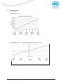
1
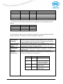
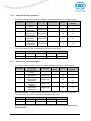
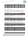
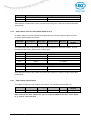
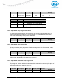
User manual Inclinometer with CANopen-Interface IK360; IK360L Table of content 1 GENERAL SAFETY ADVICE ............................................................................................................... 4 2 INTRODUCTION .................................................................................................................................... 5 2.1 2.2 2.3 3 IK360; IK360L .................................................................................................................................. 5 CANOPEN INTERFACE ....................................................................................................................... 5 IK360; IK360L CANOPEN ................................................................................................................ 6 IK360 – MODES AND PARAMETERS ................................................................................................ 6 3.1 OPERATING MODES ........................................................................................................................... 7 3.1.1 Mode: Preoperational .............................................................................................................. 7 3.1.2 Mode: Start Operational .......................................................................................................... 7 3.1.3 Mode: Stop Operation ............................................................................................................. 8 3.1.4 Reset of the inclinometer ........................................................................................................ 8 3.1.5 Reset communication of the inclinometer.............................................................................. 8 3.2 TRANSMISSION MODES ...................................................................................................................... 9 3.3 BOOT-UP PROCEDURE ....................................................................................................................... 9 4 INSTALLATION ................................................................................................................................... 10 4.1 4.2 4.3 4.4 4.5 5 IK360; IK360L SOFTWARE CONFIGURATION............................................................................... 13 5.1 5.2 5.3 5.4 5.5 6 PIN ASSIGNMENT ............................................................................................................................. 10 INSTALLATION PRECAUTIONS ........................................................................................................... 10 MOUNTING INSTRUCTIONS ............................................................................................................... 10 BUS TERMINATION ........................................................................................................................... 11 MEASUREMENT AXIS ........................................................................................................................ 12 IMPORTANT FACTORY SETTINGS ...................................................................................................... 13 ACTIVE PROGRAMMING OBJECTS ..................................................................................................... 13 PROGRAMMABLE PARAMETERS ....................................................................................................... 13 PDO TRANSMISSION ....................................................................................................................... 15 EXPLICIT EXCHANGES (SDO).......................................................................................................... 17 WORKING WITH SCHNEIDER PLC.................................................................................................. 19 6.1 INTRODUCTION ................................................................................................................................ 19 6.2 NETWORK INITIALIZATION ................................................................................................................ 19 6.2.1 Hardware................................................................................................................................ 19 6.2.2 Software project information ................................................................................................. 20 6.3 CONFIGURATION .............................................................................................................................. 21 6.4 DEBUGGING .................................................................................................................................... 24 6.5 RUN ................................................................................................................................................ 25 7 TROUBLESHOOTING......................................................................................................................... 27 8 IK360; IK360L CANOPEN OBJECTS ............................................................................................... 29 8.1 8.2 8.3 8.4 8.5 8.6 8.7 8.8 8.9 8.10 8.11 8.12 OBJECT 1000H: DEVICE T YPE ......................................................................................................... 29 OBJECT 1001H: ERROR REGISTER ................................................................................................. 29 OBJECT 1003H: PRE-DEFINED ERROR FIELD .................................................................................. 29 OBJECT 1005H: COB-ID SYNC....................................................................................................... 30 OBJECT 1008H: MFR DEVICE NAME ................................................................................................ 30 OBJECT 1009H: MFR HARDWARE VERSION .................................................................................... 30 OBJECT 100AH: MFR SOFTWARE VERSION..................................................................................... 30 OBJECT 100CH: GUARD TIME ......................................................................................................... 30 OBJECT 100DH: LIFE TIME FACTOR ................................................................................................ 30 OBJECT 1010H: STORE PARAMETERS ............................................................................................ 31 OBJECT 1011H: RESTORE PARAMETERS ........................................................................................ 31 OBJECT 1014H: COB-ID EMERGENCY............................................................................................ 32 IK360; IK360L-CAN x Date: 08.08.2013 Page 2 of 42 Art.no. 86089 Mod. Status 292/13 8.13 8.14 8.15 8.16 8.17 8.18 8.19 8.20 8.21 8.22 8.23 8.24 8.25 8.26 8.27 8.28 8.29 8.30 8.31 8.32 8.33 8.34 8.35 9 OBJECT 1016H: CONSUMER HEARTBEAT TIME ............................................................................... 32 OBJECT 1017H: PRODUCER HEARTBEAT TIME ................................................................................ 32 OBJECT 1018H: IDENTITY OBJECT .................................................................................................. 32 OBJECT 2200H: CYCLIC TIMER ....................................................................................................... 33 OBJECT 2300H: SAVE PARAMETER WITH RESET ............................................................................. 33 OBJECT 2600H: PRESET X-AXIS (IK360; IK360L-2 AXIS) / PRESET (IK360; IK360L-1 AXIS) ........ 33 OBJECT 2601H: PRESET Y-AXIS (IK360; IK360L-2 AXIS) ............................................................... 34 OBJECT 3000H: NODE NUMBER ...................................................................................................... 34 OBJECT 3001H: BAUD RATE ............................................................................................................ 35 OBJECT 3002H: TERMINATION RESISTOR ....................................................................................... 35 OBJECT 3022H: DIGITAL RECURSIVE FILTER................................................................................... 35 OBJECT 3100H: MOVING AVERAGE FILTER ..................................................................................... 36 OBJECT 6000H: RESOLUTION ......................................................................................................... 36 OBJECT 6010H: SLOPE LONG16 ..................................................................................................... 36 OBJECT 6011H: SLOPE LONG16 OPERATING PARAMETER ............................................................... 36 OBJECT 6012H: SLOPE LONG16 PRESET VALUE ............................................................................. 37 OBJECT 6013H: SLOPE LONG16 OFFSET ......................................................................................... 37 OBJECT 6014H: DIFFERENTIAL SLOPE LONG16 OFFSET .................................................................. 37 OBJECT 6020H: SLOPE LATERAL16................................................................................................. 38 OBJECT 6021H: SLOPE LATERAL16 OPERATING PARAMETER .......................................................... 38 OBJECT 6022H: SLOPE LATERAL16 PRESET VALUE ......................................................................... 39 OBJECT 6024H: DIFFERENTIAL SLOPE LATERAL16 OFFSET ............................................................. 39 OBJECT 6114H: DIFFERENTIAL SLOPE LONG32 OFFSET .................................................................. 39 OUTPUT GRAPHS .............................................................................................................................. 40 GLOSSARY.................................................................................................................................................. 42 IK360; IK360L-CAN x Date: 08.08.2013 Page 3 of 42 Art.no. 86089 Mod. Status 292/13 1 General Safety Advice Read these instructions carefully and have a look at the equipment to become familiar with the device before trying to install, operate or maintain it. The following special messages may appear throughout this documentation & on the equipment to warn of potential hazards or to call attention towards information that clarifies / simplifies a procedure. The addition of this symbol to a Danger or Warning safety label indicates that an electrical hazard exists, which will result in personal injury, if the instructions are not followed. This is the safety alert symbol. It is used for alerting, in case of potential personal injury or hazards. Obey all safety messages that follow this symbol to avoid possible injury or death. Please Note Electrical equipment should be serviced only by qualified personnel. No responsibility is assumed by SIKO for any consequences arising out of the use of this material. This document is not intended as an instruction manual for untrained persons. About this manual This user manual explains how to install and configure the IK360 inclinometer with a CANopen interface by illustrations. IK360; IK360L-CAN x Date: 08.08.2013 Page 4 of 42 Art.no. 86089 Mod. Status 292/13 2 2.1 Introduction IK360; IK360L IK360; IK360L inclinometers sense and measure the angle of tilt (Inclination/Slope/Elevation) of an object with respect to the force of gravity. The angle is measured with the relative change in electrical capacitance. The basic principle behind this IK360; IK360L inclinometer is a Micro-Electro-Mechanical Systems (MEMS) sensor cell, that is embedded to a fully molded ASIC. A simplified version of the sensor consists of two electrodes, one is fixed, and the other is flexible (connected with spring elements). When the inclinometer is parallel to the surface of measurement, a corresponding capacitance is measured. If the sensor is tilted, the flexible electrode will change its position relative to the fixed electrode. This results in a change of the capacitance between the two electrodes, which is measured by the sensor cell. The change of the capacitance is converted to a corresponding inclination value. Absolute inclinometers identify all the points of a movement by means of an unambiguous signal. Due to their capacity to give clear and exact values to all inclinations positions, inclinometers have become one of the interesting alternatives to singleturn absolute (and incremental) encoders and a link between the mechanical and control systems. 2.2 CANopen interface CANopen is based on the Controller Area Network (CAN), that was developed by automotive industries in the 80s and is nowadays used in many industrial applications. The application protocol CANopen was introduced by the multi vendor association CAN in Automation (CiA) to ensure a full compatibility of industrial automation products. It is a multiple access system (maximum: 127 nodes), which means that all devices can access the bus. These devices/nodes are the components of the CANopen bus and in our case the node is the IK360; IK360L inclinometer. In simple terms, CANopen works as a client-server model. Each device checks whether the bus is free and if it is free the device can send messages. If two devices try to access the bus at the same time, the device with the higher priority level (lowest ID number) has permission to send its message. Devices with the lowest priority level must cancel their data transfer and wait before re-trying to send their message. Data communication is carried out via messages. These messages consist of a unique COB-ID (refer to glossary) followed by a maximum of 8 bytes of data. The COB-ID, which determines the priority of the message, consists of a function code and a node number. The node number corresponds to the network address of the device. It is and has to be unique on a bus in order to distinguish nodes and prevent any conflict of interests. The function code varies according to the type of message being sent: Management messages (LMT, NMT) Messaging and service (SDOs) Data exchange (PDOs) Predefined messages (Synchronization, Emergency messages) IK360; IK360L-CAN x Date: 08.08.2013 Page 5 of 42 Art.no. 86089 Mod. Status 292/13 2.3 IK360; IK360L CANopen The IK360; IK360L CANopen inclinometer corresponds to the CANopen device profile for inclinometer DS 410, in which the characteristics of inclinometers with CANopen interface are defined. In addition to high resolution, accuracy and protection class of IP69K, it has in-built active linearization and temperature compensation. This makes IK360; IK360L suitable for rugged environments and versatile applications in industrial, heavy duty and military applications. The inclinometer supports the following operating modes: Polled mode: The position value is transmitted only on request. Cyclic mode: The position value is sent cyclically (regular, adjustable intervals) on the bus. SYNC mode: The position value is sent, after a synchronization message (SYNC) is received. The position value is sent every n SYNCs (n ≥ 1). State change mode: The position value is transmitted, whenever the position of the inclinometer, in continuous operation, changes. The CANopen interface of the IK360; IK360L inclinometer permits transmission rates of up to 1 MBaud/s (30 m / 100 ft cable for a maximum speed of 1 MBaud/s, 5000 m / 16,500 ft cable for a maximum speed of 10 kBaud/s). The IK360; IK360L CANopen is a flexible measurement device. This is proved by the fact, that it has easily programmable parameters like resolution, preset and software filters. Other functions such as offset values, baud rate and node number can also be configured using CANopen objects in the IK360; IK360L inclinometers with ease and according to the network. Various software tools for configuration and parameter-setting are available from different suppliers. It is easy to align and program the inclinometers using the EDS (electronic data sheet) configuration file provided. 3 IK360; IK360L – Modes and Parameters The purpose of this chapter is to describe all the available configuration parameters of the IK360; IK360L inclinometers with a CANopen interface. Before going into details the following information describes useful technical terms and acronyms for CANopen network communication. EDS (Electronic Data Sheet) An EDS file describes the communication properties of a device on the CAN network (baud rates, transmission types, I/O features, etc.). It is provided by the device manufacturer and is used in the configuration tool to configure a node. PDO (Process Data Object) CANopen frame containing I/O data. We distinguish between: Transmit-PDOs (TPDOs with data provided by a node). Receive-PDOs (RPDOs with data to be consumed by a node). The transmission direction is always seen from a node's point of view. IK360; IK360L-CAN x Date: 08.08.2013 Page 6 of 42 Art.no. 86089 Mod. Status 292/13 SDO (Service Data Object) CANopen frames containing parameters. SDOs are typically used to read or write parameters, while the application is running. COB-ID (Communication Object Identifier) Each CANopen frame starts with a COB-ID working as the identifier in the CAN frame. Duringthe configuration phase each node receives the COB-ID(s) of the frame(s), for which it is the provider (or consumer). The NMT protocols are used to issue state machine change commands (i. e. to start and stop the devices), detect remote device boot ups and error conditions. NMT (Network Management Protocol) 3.1 Operating modes 3.1.1 Mode: Preoperational When the device is in this state, its configuration can be modified. However, only SDOs can be used to read or write device-related data. The device goes into "Pre-Operational" state: after the power up or on receiving the "Enter Pre-Operational" NMT indication, if it was in operational state. When configuration is complete, the device goes into one of the following states on receiving the corresponding indication: "Stopped" on receiving the "Stop Remote Node" NMT indication "Operational" on receiving the "Start Remote Node" NMT indication. To set one or all nodes to pre-operational mode, the master must send the following message: Identifier Byte 0 0h 80h 0h 80h NN: node number 3.1.2 Byte 1 00 NN (in hex) Description NMT: Pre-operational Mode, all nodes NMT: Pre-operational Mode, NN Mode: Start Operational The device goes into the "Operational" state, if it was in the "Pre-Operational" state on receiving the "Start Remote Node" indication. When the CANopen network is started using the "Node start" NMT services in "Operational" state, all device functionalities can be used. Communication is possible by PDOs or SDOs. Note: Modifications to the configuration in "Operational" mode may have unexpected consequences and should therefore only made in "Pre-Operational" mode. IK360; IK360L-CAN x Date: 08.08.2013 Page 7 of 42 Art.no. 86089 Mod. Status 292/13 To put one or all nodes in the operational state, the master has to send the following message: Identifier Byte 0 0h 01h 0h 01h NN: node number 3.1.3 Byte 1 00h NN (in hex) Description NMT: Start Remote Node, all nodes NMT: Start Remote Node, NN Mode: Stop Operation The device goes into the "Stopped" state on receiving the "Node stop" indication (NMT service), if it was in "Pre-Operational" or "Operational" state. In this state, the device cannot be configured. No service is available to read and write device-related data (SDO). Only the slave monitoring function "Node Guarding" remains active. To put one or all nodes in the stop operational state, the master has to send the following message: Identifier Byte 0 0h 02h 0h 02h NN: node number 3.1.4 Byte 1 00h NN (in hex) Description NMT: Stop Remote Node, all nodes NMT: Stop Remote Node, NN Reset of the inclinometer If a node is not operating correctly, it is advisable to carry out a reinitialization. Identifier Byte 0 0h 81h 0h 81h NN: node number Byte 1 Description 00h NN (in hex) NMT: Reset Node NMT: Reset Node After reinitialization the inclinometer accesses the bus in pre-operational mode. 3.1.5 Reset communication of the inclinometer If the communication of a node is not operating correctly, it is advisable to carry out a reset of the communication. Identifier Byte 0 0h 82h 0h 82h NN: node number Byte 1 00h NN (in hex) Description NMT: Reset Communication NMT: Reset Communication After reset of the communication, the inclinometer accesses the bus in pre-operational mode. IK360; IK360L-CAN x Date: 08.08.2013 Page 8 of 42 Art.no. 86089 Mod. Status 292/13 3.2 Transmission modes Polled mode Cyclic mode SYNC mode 3.3 By a remote-transmission-request telegram the connected host calls for the current process value. The inclinometer reads the current position value, calculates eventually set-parameters and sends back the obtained process value by the same identifier. The inclinometer cyclically transmits (without being called by the host) the current process value. The cycle time can be programmed in milliseconds for values between 0 ms and 65536 ms. After receiving a SYNC telegram by the host the inclinometer answers with the current process value. If more than one node number (encoder) shall answer after receiving a SYNC telegram, the answer telegrams of the nodes will be received by the host in order of their node numbers. The programming of an offset-time is not necessary. If a node should not answer after each SYNC telegram on the CAN network, the parameter sync counter can be programmed to skip a certain number of sync telegrams before answering again. Boot-up procedure The general boot-up procedure for the IK360; IK360L CANopen and the mapping of various modes are illustrated below. IK360; IK360L-CAN x Date: 08.08.2013 Page 9 of 42 Art.no. 86089 Mod. Status 292/13 Number 1 2 3 4 5 6 7 Description Module Power up After initialization, the module automatically goes into pre-operational mode NMT: Start Remote Node NMT: Pre-operational Mode NMT: Stop Remote Node NMT: Reset Node NMT: Reset Communication To set one or all nodes to pre-operational mode, the master must send the following message. 4 4.1 Installation Pin assignment The inclinometer is connected via a 5 pin round M12 connector (Standard M12, male connector on IK360; IK360L, female connector at connection cable). Pin 1 2 3 4 5 4.2 Description CAN Ground 10-30 V supply voltage 0 V supply voltage CAN High CAN Low Installation precautions ATTENTION !!! Do not remove or mount while the inclinometer is under power! Avert any modifications to the plastic molding! Avoid mechanical load! 4.3 Mounting instructions IK360; IK360L is a pre-calibrated device, which can be put into immediate operation, upon simple and easy installation with a three point mount and setting of preset. Its compact design and installation “anywhere” makes it versatile. IK360; IK360L-CAN x Date: 08.08.2013 Page 10 of 42 Art.no. 86089 Mod. Status 292/13 The IK360; IK360L inclinometer can be mounted in any number of fashions, depending on the situation. The mounting surface must be plane and free of dust and grease. It is absolutely necessary, that the IK360; IK360L inclinometer is connected to potential equalization in a workmanlike manner. For mounting we recommend cheese head screws with metrical thread M4 or UNC bolts #6 for the best possible and secure mounting. Use all the 3 screws for mounting, but restrict the tightening torque in the range of 1,5 – 2,5 Nm for the screws. The M12 connectors are to be perfectly aligned and screwed till the end with a tightening torque in the range of 0,4 -0,6 Nm. Use all the three screws for mounting and also note to use the same tightening torque for all the screws. An appropriate and well secured counter connector is also an important constraint for attaining the stated IP69K protection. Prior to installation, please check for all connection and mounting instructions to be complied with. Please also observe the general rules and regulations on low voltage technical devices, for safety and sustainability of IK360; IK360L Inclinometers over long period of time. 4.4 Bus termination If the inclinometer is connected at the end or beginning of the bus for higher transmission baud rates (≥ 50 kBaud/s) a termination resistor of 120 Ohm must be used in order to prevent the reflection of information back into the CAN bus. The bus wires can be routed in parallel, twisted or shielded form in accordance with the electromagnetic compatibility requirements. A single line structure minimizes reflection. The following diagram shows the components for the physical layer of a two-wire CAN-bus: PLC IK360; IK360L inclinometer 120Ω Other CAN nodes IK360; IK360L inclinometer CAN High wire CANope n Master 120 Ω CAN Low wire IK360; IK360L-CAN x Date: 08.08.2013 Page 11 of 42 Art.no. 86089 Mod. Status 292/13 4.5 Measurement axis IK360; IK360L (1 axis) Measurement axis and mid angle position (factory setting ~ connector facing down) IK360; IK360L (2 axis) IK360; IK360L-CAN x Date: 08.08.2013 Page 12 of 42 Art.no. 86089 Mod. Status 292/13 5 IK360; IK360L Software Configuration This chapter succeeds the hardware configuration (i. e. installation) as in real time. IK360; IK360L is a very flexible device and hence all the parameters can be programmed via CAN bus itself even when attached. This enables remote configuration. This chapter is primarily divided into two parts. In first part the methodology is described for putting the IK360; IK360L into operation and in the second part the PDO/SDO programming of IK360; IK360L. 5.1 Important factory settings Description Object Device Type 1000h Cyclic Timer Resolution Node Number Baud Rate PDOs 2200h 6000h 3000h 3001h 6010h Value 0 x 3019A (IK360; IK360L 1 axis) 0 x 4019A (IK360; IK360L 2 axis) 00h (0 ms) 0Ah (0.01°) 00h (NN = 1) 03h (125 kB) Note: The factory settings should be noted carefully upon installation. Few of the parameters have to be re-programmed in order to make the IK360; IK360L inclinometers compatible with the controller or the already existing CAN bus to which it is going to be installed on. 5.2 Active programming objects Active CANopen objects depending on the state of IK360; IK360L. The crosses in the table below indicate, which CANopen objects are active in each state. Initialization PDO Object SDO Object Boot-Up NMT 5.3 Pre-Operational X X X Operational Stopped X X X X X Programmable parameters Objects are based on the CiA 301 DS and CiA 410 DS V1.2. The following table gives the list of command identifiers sent and received by the inclinometer. These are the standard commands used for communication and transmission between a master and slave in the CAN bus. It is quite useful for the analysis of communication logs between the master and slave and for better understanding of the system under observation. IK360; IK360L-CAN x Date: 08.08.2013 Page 13 of 42 Art.no. 86089 Mod. Status 292/13 Command Function 22h SDO Upload 60h SDO Upload 40h SDO Download 43h, 4Bh, 4Fh (*) SDO Download 80h Warning Table 1: Command description Telegram Request Confirmation Request Reply Reply Description Parameter to IK360; IK360L Acknowledge “Parameter received” Parameter request Parameter to Master Transmission error (*) The value of the command byte depends on the data length of the called parameter (see table 2). Command Data length 43h 4 Byte 4Bh 2 Byte 4Fh 1 Byte Table 2: Data length of commands Data length Unsigned 32 Unsigned 16 Unsigned 8 The following list of objects is the most frequently used objects, while programming the IK360; IK360L inclinometer. The whole list of objects is available in appendix A. Position Value (Objects 6010h and 6020h) Store Parameters (Objects 1010h, 2300h) Resolution per 1° (Object 6000h) Operating Parameter (Object 6011h) IK360; IK360L-CAN The object 6010h and 6020h are used to get the scaled inclination positions (integer 16 variables) of IK360; IK360L-2 axis in the range of ±80° and the object 6010h is used to get the scaled inclination position of IK360; IK360L-1 axis in the range of 0 – 359.99°. These objects are used to store any re-configured parameters. Object 1010h just stores the parameters, whereas 2300h stores and saves the parameters upon reset of the IK360; IK360L. The parameter, resolution per degree, is used to program the desired number of angular divisions per revolution. The values 1, 10, 100 can be programmed. With the operating parameter it is possible to change the sense of rotation (inversion) and switch on/off the scaling. For using the preset function the scaling has to be switched on. x Date: 08.08.2013 Bit 1 Bit 0 Position Calculation 0 0 X 0 1 1 0 1 1 Page 14 of 42 -X (10000h – X für 16 bit objects, 100000000h – X for 32bit objects) (X + Object 6013h + Object 6014h) (-X + Object 6013h + Object 6014h) Art.no. 86089 Mod. Status 292/13 Preset Value (Object 6012h) The preset value is the desired position value, which should be reached at a certain physical position of the axis. The position value is set to the desired process value by the parameter preset, when scaling is switched on. IK360; IK360L-2 axis used Object 6012h for X-Axis and Object 6013h for Y-Axis. IK360; IK360L-1 axis used Object 6012h for the Z-Axis. The setting of the node number is achieved via SDO-Object. Possible (valid) addresses lie between 1 and 127, but each address can only be used once. The baud rate can be programmed via SDO. Node Number (Object 3000h) Baud rate (Object 3001h) Filter (Objects 3100h/3022h) Filter can be used to adjust the frequency of measurements and calculation of position values. Object 3100h corresponds to moving average filter and 3022h is for digital recursive filter. Default: Object 3100h, Object 3022h: 0). Appendix A has a detailed list of all the objects, which can be programmed with IK360; IK360L CANopen. The data type, data size, default value, r/w access definition and all sub-indexes are mentioned in it. It is necessary to read the appendix A for clear knowledge before programming. Appendix A has a lot of important programming tips, which are necessary for the proper use of the inclinometer. 5.4 PDO Transmission Process Data Objects (PDOs) communicate process information / data and enable them to be exchanged in real time. A CANopen device's PDO set describes the implicit exchanges between this device and its communication partners on the network. The exchange of PDOs is authorized, when the device is in "Operational" mode. Note: The PDOs can be directly mapped in to memory locations on the controller and can be viewed upon reading those memory locations. An example is provided in the next section with a SCHNEIDER-TWIDO controller. Object 1800h: 1st Transmit PDO communication parameter This object contains the communication parameter of the 1st transmit PDO. Subindex * Description Data Type Default Value Access Restore after BootUp Number of sub Unsigned 8 5 ro yes indices 01h COB-ID Unsigned 32 180h + Node ID rw yes Transmission 02h Unsigned 8 0xFE rw yes Mode 03h Inhibit Time Unsigned 32 0x00 rw yes 04h Not Available 05h Event Timer Unsigned 32 0x00 rw yes * Subindex: Second degree identifier used in combination with the object. (Follows the object numbe 00h IK360; IK360L-CAN x Date: 08.08.2013 Page 15 of 42 Art.no. 86089 Mod. Status 292/13 Object 1801h: 2nd Transmit PDO communication parameter This object contains the communication parameter of the 2nd transmit PDO. Subindex * Description Data Type Default Value Access Restore after BootUp Number of sub Unsigned 8 5 ro yes indices 01h COB-ID Unsigned 32 280h + Node ID rw yes Transmission 02h Unsigned 8 0xFE rw yes Mode 03h Inhibit Time Unsigned 32 0x00 rw yes 04h Not Available 05h Event Timer Unsigned 32 0x00 rw yes * Subindex: Second degree identifier used in combination with the object. (Follows the object number) 00h Transmission mode The transmission mode (Sub index 2) for Objects 1800 and 1801 can be configured as described below. Transfer Value (Dec) Cyclic 0 1-240 Transmission Mode Synchr- AsynchrAcyclic onous onous X X Send PDO on first sync message following an event Send PDO every x sync messages X X 241-251 Notes RTR Only Reserved 252 X X 253 X 254 X 255 X Receive sync and send PDO on remote transmit request Update data and send PDO on remote transmit request Send PDO on event (eventtimer is expired) Send PDO on Event (position value has changed) Inhibit Time The "inhibit time" for PDO transmissions can be entered in this 16 bit field. If data is changed, the PDO sender checks whether an "inhibit time" has expired since the last transmission. A new PDO transmission can only take place, if the "inhibit time" has expired. The "inhibit time" is useful for asynchronous transmission (transmission mode 254 and 255), to avoid overloads on the CAN bus. Event Timer The "event timer" only works in asynchronous transmission mode (transmission mode 254 and 255). If the data changes before the "event timer" expires, a temporary telegram is sent. If a value > 0 is written in this 16-bit field, the transmit PDO is always sent after the "event timer" expires. The value is written in sub index 5 of the object 1800 or 1801. The data transfer also takes place with no change to data. The range is between 1-65536 ms. IK360; IK360L-CAN x Date: 08.08.2013 Page 16 of 42 Art.no. 86089 Mod. Status 292/13 Cyclic Timer The cyclic timer is useful to set the position transmission to cyclic mode. The cyclic timer can be programmed from 0ms to 65536 ms. When enabled, the IK360; IK360L transmits the position value contained in the PDO at constant prescribed intervals, even if there is no change in the position value. Object 2200h is used to set the cyclic timer value. Object 1A00h: 1st Transmit PDO Mapping parameter This object contains the mapping parameter of the 1st transmit PDO. Subindex * Description Data Type 0 Number of sub indices Unsigned 8 1 2 Mapped object Mapped object Unsigned 32 Unsigned 32 Default Value 80° (IK360; IK360L-2 axis) 360° (IK360; IK360L-1 axis) 6010 00 10 6020 00 10 Access Restore after BootUp ro yes rw rw yes yes Access Restore after BootUp ro yes rw rw yes Yes Object 1A01h: 2nd Transmit PDO Mapping parameter This object contains the mapping parameter of the 2nd transmit PDO. 5.5 Subindex * Description Data Type 0 Number of sub indices Unsigned 8 1 2 Mapped object Mapped object Unsigned 32 Unsigned 32 Default Value 80° (IK360; IK360L-2 axis) 360° (IK360; IK360L-1 axis) 6010 00 10 6020 00 10 Explicit Exchanges (SDO) Service Data Objects (SDOs) allow a device's data to be accessed by using explicit requests. The SDO service is available, when the device is in "Operational" or "Pre-Operational" state. Types of SDO There are two types of SDO: Read SDOs (Download SDOs), Write SDOs (Upload SDOs). The SDO protocol is based on a 'Client / Server' model: For a download SDO: The server sends a request, indicating the object to be read. The client returns the data contained within the object. IK360; IK360L-CAN x Date: 08.08.2013 Page 17 of 42 Art.no. 86089 Mod. Status 292/13 For an upload SDO: The server sends a request, indicating the object to be written to and the desired value. After the object has been updated, the client returns a confirmation message. For an unprocessed SDO: In both cases, if a SDO could not be processed, the device / master returns an error code. A typical illustration of SDO for reading the current baud rate value explicitly is given below: SDO passed as a new message to the device We used a PEAK™ CAN master for this illustration. The PCAN®-USB adapter enables simple connection to CAN networks. The PCAN®-USB’s compact plastic casing makes it suitable for mobile applications. It works as a master on the CAN bus connection via D-Sub, 9-pin and in accordance with CiA 102 standards. Object 3001h is to read the baud rate value from the IK360; IK360L. Transmit message ID: 601h - Message to node number 1 Length: 8 byte Data 0: Read (40h) Data 1 & 2 : Object in big endian (30 01 is 01 30 in big endian format) Data 3: Sub-Index (NA) Data 4-7: Data to be written (NA in read command) The received message ID: 581h - message from node number 1 Data 0: length of data is 1 byte Data 4-7: 01 equates 50 kBaud/s Received Message from the device IK360; IK360L-CAN x Date: 08.08.2013 Page 18 of 42 Art.no. 86089 Mod. Status 292/13 So, SDOs can be used to explicitly read or write data in IK360; IK360L. All the relevant objects, that can be configured, are described in Appendix A. In the above example 701h is the boot up message received. Then once we transmit the SDO command as shown above, we receive a reply. The received message, 581h, consists of the SDO downloaded. 6 Working with Schneider PLC 6.1 Introduction An IK360; IK360L, single axis inclinometer was connected to a TWIDO programmable logic controller with a CANopen communication interface. The step-by-step connection procedure and the working of inclinometer in a CAN bus is illustrated in the following sections. Please note, that the programming in other control systems may vary individually. Please have this section as a reference for IK360’s; IK360L’s working with programmable logic controllers. 6.2 Network initialization 6.2.1 Hardware The initial step in setting up an IK360; IK360L is integrating it into the existing hardware. The following illustration shows an IK360; IK360L integrated into a PLC with an CANopen communication interface. It is very important to add termination resistors to the IK360; IK360L, which are used at the start or end of the CANopen bus in order to prevent data corruption or missing of data at higher transmission bandwidths (≥ 50 kB). Hardware setup and wiring IK360; IK360L-CAN x Date: 08.08.2013 Page 19 of 42 Art.no. 86089 Mod. Status 292/13 6.2.2 Software project information Once the hardware setup is done, the IK360; IK360L should be configured in such a way, that it is compatible to the already existing setup and gives a proper position output. Controller Description CANopen Master Configuration IK360; IK360L-CAN x Date: 08.08.2013 Page 20 of 42 Art.no. 86089 Mod. Status 292/13 IK360; IK360L inclinometer – Electronic Data Sheet (EDS) The IK360; IK360L EDS file once uploaded will load all the objects including the PDOs to the controller. The Schneider system automatically identifies the PDOs and maps them on to the slave device. Connection network setup The illustration below describes the connection of the elements in the CAN bus. At first the CANopen communication interface is connected to the main controller. Then the inclinometer is connected to the CANopen communication interface. The next step after the setup of the network is the configuration of all the parameters and settings, to facilitate the communication between the master, slave and the controller. This picture is the overall description of the setup, with the TWIDO TWDLMDA20DTK controller, TWDNCO1M CANopen communication expansion module and the IK360; IK360L EDS file. 6.3 Configuration IK360; IK360L Process Data Objects (PDO) Mapping The list of available objects is pre-programmed in the EDS file. Select the IK360; IK360L inclinometer on the bus and click on “Configuration”. A list of all the mapped PDOs appear. Then, according to the need, the objects are mapped on to the Transmit-PDO’s of the IK360; IK360L. IK360; IK360L-CAN x Date: 08.08.2013 Page 21 of 42 Art.no. 86089 Mod. Status 292/13 IK360; IK360L CANopen node configuration Click at the IK360; IK360L inclinometer on the bus and select the CANopen configuration option. It is used to define the name, type, address and supervision of the node. Make sure the node number and the address coincide for the inclinometer selected. CANopen bus network configuration Click on the bus connecting the IK360; IK360L inclinometer and the PLC. Select the bus configuration option to define the name of the bus, the transmission speed and supervision time. Make sure, that the IK360; IK360L is programmed to the appropriate baud rate as that of the bus. IK360; IK360L-CAN x Date: 08.08.2013 Page 22 of 42 Art.no. 86089 Mod. Status 292/13 Linking of CANopen master and IK360; IK360L Transmit-PDOs Select the CANopen link of the controller. Click on the configuration option. The PDOs of the slave are mapped on the CANopen master, so that the information contained in the objects at the slave end are transmitted and saved on to the controller’s memory. IK360; IK360L & Controller memory configuration The current and updated position values from the IK360; IK360L encoder are mapped on to an EEPROM memory location in the controller. This memory location, in this case %IWC1.0.0 and IWC1.1.0 will always contain the slope values, obtained from the object 6010h of the IK360; IK360L, when the controller is online. IK360; IK360L-CAN x Date: 08.08.2013 Page 23 of 42 Art.no. 86089 Mod. Status 292/13 6.4 Debugging The debugging stage is done on completing the configuration of the PDO’s. It involves the following steps: The serial communication port is selected and PC-> controller transfer is initiated. Once the transfer is initiated the configured parameters and the programming done on the PC is debugged and transferred to the controller for real time application. The following illustrations are the intermediate tasks during debugging. Creating a backup of the controller parameters before going into online mode……. Once the controller goes into the online mode, the PDOs cannot be changed. But, we can program the SDOs as need arises. IK360; IK360L-CAN x Date: 08.08.2013 Page 24 of 42 Art.no. 86089 Mod. Status 292/13 6.5 Run Once debugged, the controller goes into online mode. After we can program the SDOs if needed and then run the controller. Upon start up, we can create an animation table to monitor the necessary controller parameters and the system variables, which contain the position value. Now we will program the PLC in order to obtain the position values. Resetting CANopen communication Resetting CANopen nodes Switch to operational mode IK360; IK360L-CAN x Date: 08.08.2013 Page 25 of 42 Art.no. 86089 Mod. Status 292/13 Position readout position value Readout using animation table Illustration of measurement over full range: At initial position (approximately 0°): IK360; IK360L position value = 32 * 0.01 = 0.32° At approximately 90°: IK360; IK360L-CAN x Date: 08.08.2013 Page 26 of 42 Art.no. 86089 Mod. Status 292/13 IK360; IK360L position value = 9138 * 0.01 = 91.38° At approximately 180°: IK360; IK360L position value = 18052 * 0.01 = 180.52° At approximately 270°: IK360; IK360L position value = 27256 * 0.01 =272.56° All the above position values where obtained by programming the position value output explicitly. The other method is very simple and direct. Just run the controller and same position values are obtained. The position is mapped with the memory location %IWC1.0.0 or %IWC1.1.0 through PDO mapping done in the earlier steps. The steps for the mapping have been illustrated in above parts so that, in real time application, end users can directly follow the above steps to read out the position values from the mapped memory locations. 7 Troubleshooting Power on – Inclinometer doesn’t respond Problem: If the bus is active, than the installed inclinometer is transmitting a false node number. If the bus is inactive, then it was connected with an incorrect baud rate. Possible solution: Modus pre-operational Adressing the inclinometer via SDO Reset or power off Reprogram the baud rate Malfunction of the position value during transmission Problem: During the transmission of the position valueoccasional malfunctions occur. The CAN bus also can be temporabily in the bus off state. Possible solution: Please check, if the last bus nodes have the terminal resistor. If the last bus node is an inclinometer, add a terminal resistor. IK360; IK360L-CAN x Date: 08.08.2013 Page 27 of 42 Art.no. 86089 Mod. Status 292/13 Too many ERROR-Frames Problem: The bus load is too high in case of too many error frames. Possible solution: Check, if all bus nodes have the same baud rate. Even if one node has a different baud rate, error frames are produced automatically. Unexpected module / Module missing / Wrong module Problem: Improper definition of node address or improper loading of EDS file. Solution: Reinitialize the CAN bus or re-install the EDS file. Node state stopped upon loading and initialization Problem: Mostly because the bus transmission timeout is defined lesser than the IK360; IK360L transmission time. Solution: Increase the bus timeout period (approximately 2-3 seconds). Unable to change to another node number If all nodes are found to be in operational mode, than follow the next few steps to set the required node number to a selected device. 1. Calculate the required node number in hexadecimal. (IK360; IK360L is internally programmed to add 1 to any node number change fed to it, in order to avoid the node number 0) 2. For example: If we want a Node Number = 28 dec, we need to feed 27 decimal (27 + 1 = 28). So the Node Number 1B hex has to be fed in order to set the selected device to node number 28. 3. Send a write telegram to the particular node, with 1B as data on the object 3000h. 4. Use 2300h to save the parameters with the reset. 5. A boot up message with the new node number pops us. IK360; IK360L-CAN x Date: 08.08.2013 Page 28 of 42 Art.no. 86089 Mod. Status 292/13 8 8.1 IK360; IK360L CANopen objects Object 1000h: Device Type The object at index 1000h describes the type of device and its functionality. It is composed of a 16-bit field, which describes the device profile, that is used, and a second 16-bit field, which gives additional information about optional functionality of the device. The additional information parameter is device profile specific. Subindex Description Data Type Default Value Access Restore after BootUp 0 - Unsigned 32 0X3019Ah* 0X4019Ah** ro no *Singel Axis (IK360-1 axis) **Dual Axis (IK360-2 axis) 8.2 Object 1001h: Error Register This object is used by the device to display internal faults. When a fault is detected, the corresponding bit is therefore activated. The following errors are supported: Bit 0 Description Generic Error Comments The generic error is signaled at any error situation. The object description for error register. 8.3 Subindex Description Data Type Default Value Access 0 - Unsigned 8 N/A ro Restore after BootUp no Object 1003h: Pre-Defined Error Field The object hold the errors, that have occurred on the device and have been signaled via the Emergency object. The error code is located in the least significant word and additional information is located in the most significant word. Subindex 0 contains the number of recorded errors. Subindex 0 1 Description Number of recorded errors Most recent errors Data Type Default Value Access Restore after BootUp Unsigned 8 0 rw no Unsigned 32 - ro no To clear error Log: Write data “0” into Subindex 0 of object 1003. IK360; IK360L-CAN x Date: 08.08.2013 Page 29 of 42 Art.no. 86089 Mod. Status 292/13 8.4 Object 1005h: COB-ID Sync The object contains the synchronization message identifier. 8.5 Subindex Description Data Type Default Value Access 0 - Unsigned 32 0x80h rw Restore after BootUp no Object 1008h: Mfr Device Name The object contains the device name. 8.6 Subindex Description Data Type Default Value Access 0 - String - ro Restore after BootUp no Object 1009h: Mfr Hardware Version The object contains the article name of the circuit board. 8.7 Subindex Description Data Type Default Value Access 0 - String - ro Restore after BootUp no Object 100Ah: Mfr Software Version The object contains the manufacturer software version. 8.8 Subindex Description Data Type Default Value Access 0 - String - ro Restore after BootUp no Object 100Ch: Guard Time The object contains the guard time in milliseconds. 8.9 Subindex Description Data Type Default Value Access 0 - Unsigned 16 0 rw Restore after BootUp yes Object 100Dh: Life Time Factor This object contains the life time factor parameters. The life time factor multiplied with the guard time gives the life time for the node guarding protocol. Subindex Description Data Type Default Value Access 0 - Unsigned 8 0 rw IK360; IK360L-CAN x Date: 08.08.2013 Page 30 of 42 Art.no. 86089 Restore after BootUp yes Mod. Status 292/13 8.10 Object 1010h: Store Parameters This object is used to store device and CANopen related parameters to non volatile memory. Subindex Description Data Type Default Value Access Restore after BootUp Number of sub Unsigned 8 4 ro no indices Save all 1 Unsigned 32 rw no parameters Save 2 communicatio Unsigned 32 rw no n parameters Save 3 application Unsigned 32 rw no parameters Save 4 manufacture Unsigned 32 rw no parameters Storing Procedure: To save the parameters to non-volatile memory, the access signature “save” has to be sent to the corressponding (sub-)index of the device. 0 ASCII Hex value 8.11 Most significant word e v 65h 76h Least significant word a s 61h 73h Object 1011h: Restore Parameters This object is used to restore device and CANopen related parameters to factory settings. Subindex 0 1 2 3 4 Description Number of sub indices Restore all parameters Restore communication parameters Restore application parameters Restore manufacture parameters Data Type Default Value Access Restore after BootUp Unsigned 8 4 ro no Unsigned 32 - rw no Unsigned 32 - rw Unsigned 32 - rw no Unsigned 32 - rw no no Storing procedure: To load the parameters from non volatile memory the access signature “load” has to be sent to the corresponding (sub-)index of the device. ASCII Hex value Most significant word d a 64h 61h Least significant word o l 6Fh 6Ch Note: The restoration of parameters will only be taken into account after a power up or reset command. IK360; IK360L-CAN x Date: 08.08.2013 Page 31 of 42 Art.no. 86089 Mod. Status 292/13 8.12 Object 1014h: COB-ID Emergency This object indicates the configured COB-ID for the emergency write service. This has the highest priority among transmitted messages. 8.13 Subindex Description Data Type Default Value Access 0 - Unsigned 32 0x81 rw Restore after BootUp yes Object 1016h: Consumer Heartbeat Time The consumer heartbeat time defines the expected heartbeat cycle time in ms. The device can only monitor one corresponding device. If the time is set to 0 the monitoring is not active. The value of this object must be higher than the corresponding time (object 1017) of the monitored device. Subindex 0 1 Description Number of sub indices Consumer heartbeat time Data Type Default Value Access Restore after BootUp Unsigned 8 1 ro yes Unsigned 32 0 rw yes The context of subindex 1 is as follows: Bit Value 8.14 31 to 24 0h (reserved) 23 to 16 Address of monitored device 15 to 0 Monitoring time (ms) Object 1017h: Producer Heartbeat Time The object contains the time interval in milliseconds, in which the device has to produce a heartbeat message. 8.15 Subindex Description Data Type Default Value Access 0 - Unsigned 16 0 rw Restore after BootUp yes Object 1018h: Identity Object This object provides the general identification of the inclinometer. Subindex 0 1 2 IK360; IK360L-CAN Description Number of sub entries Vendor Id Product Code x Date: 08.08.2013 Data Type Default Value Access Restore after BootUp Unsigned 8 0x4 ro no Unsigned 32 Unsigned 32 0x195 0x43415032 ro ro no no Page 32 of 42 Art.no. 86089 Mod. Status 292/13 Subindex Description Data Type Default Value Access Restore after BootUp 0x00010500* ro no - ro no Revision Unsigned 32 Number 4 Serial Number Unsigned 32 *Prone to change with every revision 3 8.16 Object 2200h: Cyclic Timer This object is used to determine the transmission interval during cylic transmission mode. This object is hardwired with the event timers of TxPDO1 and TxPDO2. If cyclic timer and event timers od TxPDOs hold different values after power off/on cycle, the value of the event timers is copied to the cycle time. 8.17 Subindex Description Data Type Default Value Access 0 - Unsigned 16 0 rw Restore after BootUp yes Object 2300h: Save Parameter with Reset With this object all parameters can be stored in the non volatile memory. After storing the parameters a reset is executed. 8.18 Subindex Description Data Type Default Value Access 0 Access code Unsigned 32 55AAAA55h wo Restore after BootUp no Object 2600h: Preset X-Axis (IK360; IK360L-2 axis) / Preset (IK360; IK360L-1 axis) In IK360; IK360L-1 axis inclinometers this object sets the X-axis to a desired value. In IK360; IK360L-2 axis inclinometers, this object sets the Z-axis to the desired value. It is hard-wired with objects 6012 and 6112. Restore after Subindex Description Data Type Default Value Access BootUp 0 Integer 16 rw yes The valid preset value ranges depend on the current resolution of the IK360. An error message will apear if the preset value is out of range. Resolution Type 1° 0.1° 0.01° IK360-2 axis 80 800 8000 Resolution IK360; IK360L-CAN Preset Range (in decimal) IK360-1 axis 0 - 360 0 – 3600 0 – 36000 Preset Range (in decimal) x Date: 08.08.2013 Page 33 of 42 Art.no. 86089 Mod. Status 292/13 Resolution Type 0.05° IK360L-2 axis 80 Preset Range (in decimal) IK360L-1 axis 0 - 360 After setting the Preset value a save command has to be given in order to set the Preset value permanently. 8.19 Object 2601h: Preset Y-Axis (IK360; IK360L-2 axis) In IK360; IK360L-2 axis inclinometers this object sets the Y-axis to a desired value. It is hardwired with objects 6022h and 6122h. Subindex Description Data Type Default Value Access 0 - Integer 16 - rw Restore after BootUp yes The valid preset value ranges depend on the current resolution of the IK360; IK360L. An error message will apear if the preset value is out of range. Resolution Type 1° 0.1° 0.01° Resolution Type 0.05° IK360-2 axis 80 800 8000 Preset Range (in decimal) IK360-1 axis 0 - 360 0 – 3600 0 – 36000 IK360L-2 axis 80 Preset Range (in decimal) IK360L-1 axis 0 - 360 After setting the Preset value a save command has to be given in order to set the Preset value permanently. 8.20 Object 3000h: Node Number This object contains the node number of the device. The standard node number is 1h. Subindex Description Data Type Default Value Access 0 Node Number Unsigned 8 0 rw* Restore after BootUp yes Note: To avoid the node number zero (0), one (1) will be added to the value of this object. E. g.: 1Fh+1h = 20h = 32 (dec) IK360; IK360L-CAN x Date: 08.08.2013 Page 34 of 42 Art.no. 86089 Mod. Status 292/13 8.21 Object 3001h: Baud rate This object contains the baud rate of the device. Subindex Description Data Type Default Value Access 0 Baud rate Unsigned 8 - rw* Restore after BootUp yes Eight different baud rates are provided (see table below). To adjust the baud rate only one byte is used. The default baud rate is 125 kB. Baud rate in kB 20 50 100 125 250 500 800 1000 8.22 Byte 00h 01h 02h 03h 04h 05h 06h 07h Object 3002h: Termination Resistor This object is used to activate the termination resistor in case the IK360; IK360L is used at the edges of the transmission line ( to avoid reflection of data back into the line ) and / or high transmission rates (>50 kB). Subindex Description Data Type Default Value Access Restore after BootUp 0 Activate Termination Resistor Unsigned 8 0 rw yes For Activation* – Write 1 decimal to the sub index 0 of the object. For De-activation – Write 0 decimal to the sub index 0 of the object. *If activated, the termination resistor is only enabled while the device is powered. 8.23 Object 3022h: Digital Recursive Filter This particular object controls the weighting factor of the recursive filter. If set to 0, the filter is deactivated. Valid values range from 0 to 1000. The value specifies the weighting factor for the slope values obtained earlier, divided by 1000. Therefore, mathematically the weighting factor ranges from 0 to 1. IK360; IK360L-CAN x Date: 08.08.2013 Page 35 of 42 Art.no. 86089 Mod. Status 292/13 8.24 Subindex Description Data Type Default Value Access Restore after BootUp 0 Digital Recursive Filter Unsigned 16 0 rw yes Object 3100h: Moving Average Filter This object contains the number of values, which are averaged. Subindex Description Data Type Default Value Access Restore after BootUp 0 Moving Average Filter Unsigned 16 100 rw yes Range of values accepted: 0d to 250d. 8.25 Object 6000h: Resolution This object sets the resolution per 1°. Subindex Description Data Type Default Value Access 0 Resolution Unsigned 16 - rw Restore after BootUp no Three different possible resolutions can be used: Actual angular resolution 1° 0.1° 0.01° 8.26 Value decimal Byte hex 1000 100 10 3E8h 64 0Ah Object 6010h: Slope long16 In IK360; IK360L -1 axis inclinometers this object provides the Z-axis value and in IK360; IK360L -2 axis this object provides the X-axis value. 8.27 Subindex Description Data Type Default Value Access 0 - Integer 16 - ro Restore after BootUp no Object 6011h: Slope long16 operating parameter This object controls the scaling and inversion of the slope long16 values. If bit 0 is set, inversion of slope long16 is enabled. If bit 1 is set, slope long16 offset and differential slope long16 offset are added to the slope long16. Both bits can be at the same time. IK360; IK360L-CAN x Date: 08.08.2013 Page 36 of 42 Art.no. 86089 Mod. Status 292/13 8.28 Subindex Description Data Type Default Value Access Restore after BootUp 0 Position Scaling and Inversion Unsigned 8 00 rw no Bit 1 0 Bit 0 0 0 1 1 1 0 1 Position Calculation X -X (10000h – X für 16 bit objects, 100000000h – X for 32bit objects) (X + Object 6013h + Object 6014h) (-X + Object 6013h + Object 6014h) Object 6012h: Slope long16 preset Value In IK360 inclinometers this object used to define an new desired longitudinal slope value. The values will be set only according to the current resolution, so extreme care should be taken in order to be within the range of the position value limits. 8.29 Subindex Description Data Type Default Value Access 0 Preset Value Integer 16 00 rw Restore after BootUp no Object 6013h: Slope long16 offset This parameter is recalculated everytime Slope Long16 preset (6012h), Slope Long32 Preset (6112h) or Preset X (2600h) objects are changed. This object does not exist for IK360; IK360L, only IK360-2 axis. Subindex Description Data Type Default Value Access 0 Preset Value Integer 16 00 rw Restore after BootUp no Calculation of Slope Long16 Offset: Offset Value = Preset Value –(Physical Value x Inversion) 8.30 Object 6014h: Differential slope long16 offset This parameter adds an additional, independent offset to slope long16, but only if scaling of slope long16 is enabled. Please note that the values sholud be within the range of position attribute according to the resolution already set. Subindex Description Data Type Default Value Access 0 Offset Value Integer 16 - rw IK360; IK360L-CAN x Date: 08.08.2013 Page 37 of 42 Art.no. 86089 Restore after BootUp no Mod. Status 292/13 The main difference between the objects 6013h and 6014h is that, 6013h is calculated automatically depending on the preset value whereas object 6014h is user defined. 8.31 Object 6020h: Slope lateral16 In IK360-2 inclinometers this object provides the Y-axis position value. Subindex Description Data Type Default Value Access 0 - Integer 16 - ro Resolution Type 1° 0.1° 0.01° Restore after BootUp no Preset Range (in decimal) IK360-2 axis 80 800 8000 Calculation of position / slope value from CANopen readout: Inclination (Degree) = Slope Lateral16(Object 6020h) x Resolution (Object 6000h) 8.32 Object 6021h: Slope lateral16 operating parameter This object controls the scaling and inversion of the slope lateral16 value. If bit 0 is set, inversion of slope lateral16 is enabled. If bit 1 is set, slope lateral offset and differential slope lateral16 offset are added to the slope lateral16. Both bits can be set at the same time. Subindex Description Data Type Default Value Access Restore after BootUp 0 Position Scaling and Inversion Integer 8 00 rw no Bit 1 0 Bit 0 0 0 1 1 1 0 1 IK360; IK360L-CAN x Date: 08.08.2013 Position Calculation X -X (10000h – X für 16 bit objects, 100000000h – X for 32bit objects) (X + Object 6023h + Object 6024h) (-X + Object 6023h + Object 6024h) Page 38 of 42 Art.no. 86089 Mod. Status 292/13 8.33 Object 6022h: Slope lateral16 preset value This object is used to define a new, desired lateral slope value. The value will be set only according to the current resolution, so extreme care should be taken in order to be within the range of the position value limits. Subindex Description Data Type Default Value Access 0 Preset Value Integer 16 00 rw Resolution Type 1° 0.1° 0.01° 8.34 Restore after BootUp no Preset Range (in decimal) IK360-2 axis 80 800 8000 Object 6024h: Differential slope lateral16 offset This parameter adds an additional, independent offset to slope long16, but only if scaling of slope long16 is enabled. Please note that the values sholud be within the range of position attribute according to the resolution already set. Subindex Description Data Type Default Value Access 0 Offset Value Integer 16 - rw Restore after BootUp no The main difference between the objects 6023h and 6024h is that, 6023h is calculated automatically depending on the preset value whereas object 6024h is user defined. 8.35 Object 6114h: Differential slope long32 offset This parameter adds an additional, independent offset to slope long16, but only if scaling of slope long16 is enabled. Please note that the values sholud be within the range of position attribute according to the resolution already set. Subindex Description Data Type Default Value Access 0 Offset Value Integer 32 - rw Resolution Type 1° 0.1° 0.01° IK360; IK360L-CAN Restore after BootUp no Preset Range (in decimal) IK360-1 axis -179 to +180 -1799 to +1800 -17999 to +18000 x Date: 08.08.2013 Page 39 of 42 Art.no. 86089 Mod. Status 292/13 9 Output graphs IK360; IK360L -1 axis IK360; IK360L -2 axis IK360; IK360L-CAN X-Achse Output Value (Resolution = 0.01) x Date: 08.08.2013 Page 40 of 42 Art.no. 86089 Mod. Status 292/13 IK360; IK360L -2 axis IK360; IK360L-CAN Y-Achse Output Value (Resolution = 0.01) x Date: 08.08.2013 Page 41 of 42 Art.no. 86089 Mod. Status 292/13 Glossary B Baudrate Transmission speed formulated in number of bits per second C CAN Controller Area Network CANopen Application layer of an industrial network based on the CAN bus. CiA CAN In Automation. Organization of manufacturers and users of devices that operate on the CAN bus. COB-ID COB-Identifier. Identifies an object in a CAN network. The ID determines the transmission priority of this object. The COB-ID consists of a function code and a node number. N NMT Network management object. This is responsible for managing the execution, configuration and errors in a CAN network. NN Node number P PDO Communication object, with a high priority for sending process data. R RO Read Only: Parameter that is only accessible in read mode. RW Read/Write: Parameter that can be accessed in read or write mode. S SDO Communication object with a low priority for messaging (configuration, error handling, diagnostics). Slave bus node, that sends data at the request of the master. The inclinometers are always slaves. W WO IK360; IK360L-CAN Write Only: Parameter that is only accessible in write mode. x Date: 08.08.2013 Page 42 of 42 Art.no. 86089 Mod. Status 292/13