1
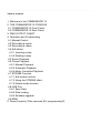
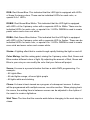
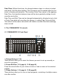
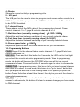
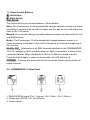
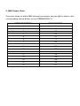
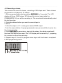
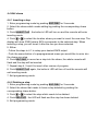
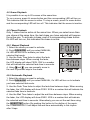
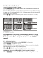
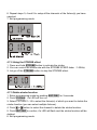
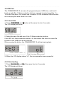
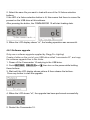
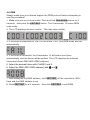
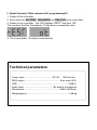
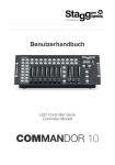
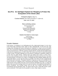
 User Manual
LED Controller Series
Controller Model
COMMANDOR 10
Table of contents
1. Welcome to the COMMANDOR 10
2. THE COMMANDOR 10 CONSOLE
2.1 COMMANDOR 10 Front Panel
2.2 COMMANDOR 10 Rear Panel
3. DMX OUTPUT CHART
4. Operation and Programming
4.1 Manual Control
4.2 Recording a scene
4.3 Recording a chase
4.4 Edit chase
4.4.1 Inserting a step
4.4.2 Deleting a step
4.5 Scene Playback
4.6 Chase Playback
4.6.1 Manual Playback
4.6.2 Automatic Playback
4.6.3 Music Controlled Playback
4.7 STROBE Function
4.7.1 Edit strobe function
4.7.2 Using the STROBE effect
4.7.3 Delete strobe function
4.8 USB Port
4.8.1 Save Data
4.8.2 Data loading
4.8.3 Software upgrade
4.9 RDM
5. Reset Console (!!!this removes ALL programming!!!)
1. Welcome to the COMMANDOR 10
Thank you for purchasing a quality product from Stagg Pro Lighting. Please read
this instruction manual carefully before operating the Commandor 10
Pictures with text in box appeared in this manual are buttons, for example:
EDIT/REC means Edit Program and Record Buttons.
The input of the power adapter supplied with the console is AC100~240V
50/60HZ, the output is DC9V 1.0A; the input of the control console is DC9V 1.0A.
Please check whether the local electrical supply is in the range of
AC100~240V and the output of the power adapter is DCDC9 V1.0A.
Before initial start-up, make sure that there is no damage caused by
transportation. Should there be any, consult your dealer and do not use this
device. To maintain perfect condition and to ensure a safe operation, it is
absolutely necessary for the user to follow the safety instructions and warning
notes in this manual.
Damage caused by user modifications or user-inflicted damage is not covered by
warranty.
This device contains no user-serviceable parts. It requires no regular
maintenance, however you should keep the unit clean. Disconnect the power
supply and then wipe the cover with a damp cloth. Never use any solvents or
alcohol to clean the device.
Terminology Glossary
Fixture: A fixture or luminaire is a product that creates artificial light. In this
manual every device that is controllable by a DMX channel will be viewed as a
fixture. This includes products like our Stagg MiniPar, FlatPar or HeadBanger
series, but also traditional dimmer packs or DJ scanners.
DMX: The digital control protocol used by intelligent lighting to send instructions
to the fixture.
RGB: Red-Green-Blue. This indicated that the LED light is equipped with LED's
of these 3 primary colors. These can be individual LED's for each color, or
special 3-in-1 LED's.
RGBW: Red-Green-Blue-White. This indicated that the LED light is equipped
with LED's of the 3 primary colors with a separate LED for White. These can be
individual LED's for each color, or special 4-in-1 LED's. RGBW is used to create
pastel colors and a true cool white.
RGBA: Red-Green-Blue-Amber. This indicated that the LED light is equipped
with LED's of the 3 primary colors with a separate LED for Amber. These can be
individual LED's for each color, or special 4-in-1 LED's. RGBW is used to create
more vivid and warm colors and a warm white.
Strobe: A lighting effect that is created trough rapidly flashing the light on and off.
Color Mixing: Just like mixing paint, mixing the 3 primary colors Red, Green and
Blue creates different colors of light. By adjusting the amount of Red, Green and
Blue in your mix you can modify the color that your fixture will project.
Scene: A scene is a preset situation that has a static DMX programming. For
example:
- All Lights Blue
- All odd lights orange, all even lights purple
- All lights white and strobing
Chase: A chase is best viewed as a program of subsequent scenes. A chase
will be programmed with multiple scenes, one after another. When playing back
the scene, the waiting time in between scenes can be adjusted to the rhythm of
the music to create a lightshow.
Wait Time: The time that the console waits before changing to the next step in a
chase.
Fade Time: Without fade time, the change between steps in a chase is instant
and harsh. A bit like disco lighting. This is however not the wanted effect for live
music or theater performances. This is where Fade Time comes in. By applying
Fade Time, the transition between steps will be done gradually making it much
smoother and softer.
Fade Time and Wait Time can be changed independently, allowing for just a hint
of Fade Time which will smoothen the change, or setting Fade Time and Wait
Time almost at the same value which will create a constant flow that seemingly
does not wait.
2. The COMMANDOR 10 console
2.1 COMMANDOR 10 Front Panel
1: Fixture Buttons (1-16)
These buttons allow you to select the fixtures you want to set up manually or
record to a program.
2: Scene Buttons (1-10 page A, 11-20 page B)
Press the scene button of your choice to store or load a scene on the selected
number.
3: Chase Buttons (1-10 page A, 11-20 page B)
These buttons allow you to store or load programs, consisting of multiple scenes
one after another.
4: Display
Shows the current activity or programming state.
5: USB port
The USB port can be used to store the programs and scenes on the console to a
USB drive, or load the programs on the USB drive to the console. The drive has
to be FAT32 formatted.
6: 7 channel faders
These faders control the DMX value of the corresponding channel. Page A
controls channels 1 to 7; page B controls channels 8 to 14.
7: Wait time fader (currently running chase) ( 0.1SEC~10MIN)
Adjusts the wait time between each step of your currently selected chase.
8: Fade time fader (currently running chase) (0~30SEC)
Adjusts the fade time between each step of your currently selected chase.
9: Strobe speed fader( 1~20HZ)
Adjusts the speed at which the strobe button will let your fixtures flash
10: Programming Buttons
PAGE: Page A lets the channel faders control channels 1-7; page B lets them
control channels 8-14.
EDIT/REC: Press and hold this button for 3 seconds, the LED next to it will light
up red and the console will enter programming mode. When in programming
mode, this button will become the RECORD button and will let you record
scenes and chases. Press and hold for 3 seconds again to return to show mode.
INSERT/TAP: In programming mode, this button let's you insert scenes between
two others in a chase. In show mode, this button is a "tap to tempo" button that
let's you adjust the wait time of the running chase to the speed you press this
button. Press the button at least three times in the rhythm you want the chase to
change between scenes.
DEL/CLR: In programming mode, this button allows you to delete chases or
scenes. In show mode, this button will clear the manual changes you have made
to DMX channels.
11: Show Control Buttons
: Left button:
: Right button:
RUN MODE:
This button will let you choose between 3 Show Modes:
Auto: The Commandor 10 will automatically change between scenes in a chase
according to the fade time set with the fader and the wait time set with either the
fader or the TAP button.
Manual: The user will change manually between scenes in a chase with the Left
and Right buttons.
Music: The Commandor 10 will automatically change between scenes in a
chase according to the beat of the music (sensed by the internal microphone of
the console).
BLACK OUT: Blackout puts all DMX channels attached to the COMMANDOR
10 to "0", creating a full off situation where no light or movement is active in the
connected fixtures. When the Blackout LED is on, Blackout mode is active.
Press the button again to return to show mode, the LED will turn off.
STROBE: Pressing this button will let the connected fixtures strobe at the set
strobe channel.
2.2. COMMANDOR 10 Rear Panel
1: DMX512/RDM output (Pin 1: Ground, Pin 2: Data -, Pin 3: Data +).
2: Power input (DC9V-12V, min 300mA).
3: Power switch.
3. DMX Output Chart
This chart shows at which DMX channel you need to set your light to listen to the
corresponding Fixture Button on the COMMANDOR 10.
FIXTURE BUTTON
1
2
3
4
5
6
7
8
9
10
11
12
13
14
15
16
DMX CHANNEL
1
15
29
43
57
71
85
99
113
127
141
155
169
183
197
211
4. Operation and Programming
4.1 Manual output
1. Select the fixture(s) you would like to control
2. Adjust the channel control faders until you acquire the desired DMX output
It is possible to control multiple fixtures of the same or a different type at the
same time. To do this:
1. Select the first fixture(s) you would like to control
2. Adjust the channel control faders
3. Deselect the fixture(s) you just controlled
4. Put all the channel faders to zero
5. Select the next fixture(s) you would like to control
6. Adjust the channel control faders
etc...
4.2 Recording a scene
This console can save 20 scenes, spread over 2 pages of 10 scenes.
1. Enter programming mode by pushing EDIT/REC for 3 seconds
2. Follow the steps in 4.1 to setup your desired DMX output
3. Push EDIT/REC to prepare for save
4. Push the scene button you want to save to, the whole console will flash and
the scene has been saved.
5. Repeat steps 2, 3 and 4 to program more scenes.
6. Exit programming mode.
Note: if you had programmed a scene on the selected scene button before, the
newly recorded scene will replace it.
4.3 Recording a chase
This console can save 20 chases, consisting of 200 steps each. These chases
are spread over 2 pages of 10 chases.
1. Enter programming mode by pushing EDIT/REC for 3 seconds. The LCD
display will show SXXX where XXX shows the current step inside the
COMMANDOR 10 you will be recording to. The console will automatically select
the last free step.
2. Push the chases button you want to record steps to.
3. Either:
- Follow the steps in 4.1 to setup your desired DMX output
- Push the scene button of a preprogrammed scene you would like to enter into
the chase as a step
4. Push EDIT/REC to record as a step into the chase, the whole console will
flash and the step will be saved. The LCD display will increment by 1, preparing
the console to record the next step.
5. Repeat steps 2, 3 and 4 to program more steps until the chase is completed.
6. Exit programming mode.
4.4 Edit chase
4.4.1 Inserting a step
1. Enter programming mode by pushing EDIT/REC for 3 seconds.
2. Select the chase which needs editing by pushing the corresponding chase
button.
3. Push INSERT/TAP , the button's LED will turn on and the console will enter
inserting mode.
4. Push or to select the location where you want to insert the new step. The
display will show SXXX where XXX corresponds to the selected step. When
inserting a step, you will insert it after the one you have selected.
5. Either:
- Follow the steps in 4.1 to setup your desired DMX output
- Push the scene button of a preprogrammed scene you would like to enter into
the chase as a step
6. Push EDIT/REC to record as a step into the chase, the whole console will
flash and the step will be inserted.
7. Repeat step 4, 5 and 6 to insert other scenes of program;
8. Push INSERT/TAP again, the button's LED will turn off and the console will
exit inserting mode.
7. Exit programming mode.
4.4.2 Deleting a step
1. Enter programming mode by pushing EDIT/REC for 3 seconds.
2. Select the chase that needs to have a step deleted by pushing the
corresponding chase button.
3. Push or to select the step which needs to be deleted.
4. Push DEL/CLR,the LED will flash and the step has been deleted.
5. Exit programming mode.
4.5 Scene Playback
It is possible to run up to 20 scenes at the same time.
To run a scene, press it's scene button and the corresponding LED will turn on.
This indicates that the scene is active. To stop a scene, press it's scene button
and the corresponding LED will turn off. This indicates that the scene is inactive.
4.6 Chase Playback
Only 1 chase can be active at the same time. When you select more than
one chase at the same time, the last chase you have selected will become
the active one. To activate a chase, push it's corresponding chase button.
It's LED will turn on, this indicates the chase is active.
4.6.1 Manual Playback
1. Select the chase you want to activate.
2. Push RUN MODE until you select MANUAL,
it's LED will turn on to indicate you have
selected that mode.
3. Use the Fade Time fader to adjust the fade
time between steps. When moving the fader,
the LCD display will show FXXX. XXX is a number
that will indicate the selected fade time in seconds.
4. Using and , you can manually move to
the next or previous step in the chase.
4.6.2 Automatic Playback
1. Select the chase you want to activate.
2. Push RUN MODE until you select MANUAL, it's LED will turn on to indicate
you have selected that mode.
3. Use the Fade Time fader to adjust the fade time between steps. When moving
the fader, the LCD display will show FXXX. XXX is a number that will indicate the
selected fade time in seconds.
4. Use the Wait Time fader to adjust the wait time between steps. When moving
the fader, the LCD display will show SXXX. XXX is a number that will indicate
the selected wait time in seconds. Alternatively you can set the wait time using
the INSERT/TAP button. By pushing this button to the rhythm of the music,
the COMMANDOR 10 will adjust the wait time automatically to this rhythm
after 3 taps.
4.6.3 Music Controlled Playback
1. Select the chase you want to activate.
2. Push RUN MODE until you select MUSIC, it's LED will turn on to indicate you
have selected that mode.
3. Use the Fade Time fader to adjust the fade time between steps. When moving
the fader, the LCD display will show FXXX. XXX is a number that will indicate the
selected fade time in seconds.
4. Push or to adjust the sensitivity of the internal microphone(0~100%).
4.7 STROBE Function
The COMMANDOR 10 can strobe a preprogrammed channel at a rate of
0-20Hz. This makes the channel flash on and off at the speed set with the
Strobe Speed fader. This is ideally either the dimmer or the R/G/B/W
channels.
4.7.1 Edit strobe function
1. Enter programming mode by pushing EDIT/REC for 3 seconds.
2. Push STROBE,it's LED will turn on.
3. Select FIXTURE 1~16 to select the fixture(s) of which you want to setup the
channel to strobe (you can select multiple fixtures).
4. Push or button to select the channel to strobe.
6. Set the channel to Yes (upper image) if you want to strobe it with the
strobe button. Set it to No (lower image) if you do not want to strobe it.
5. Push EDIT/REC to confirm, it's LED will flash and the setting will be saved.
6. Repeat steps 3, 4 and 5 to setup all the channels of the fixture(s) you have
selected.
7. Exit programming mode.
4.7.2 Using the STROBE effect
1. Press and hold STROBE button to activate the strobe.
2. You can control the strobe rate with the STROBE SPEED fader(1-20Hz).
3. Let go off the STROBE button to stop the STROBE effect.
4.7.3 Delete strobe function
1. Enter programming mode by pushing EDIT/REC for 3 seconds.
2. Push STROBE,it's LED will turn on.
3. Select FIXTURE 1~16 to select the fixture(s) of which you want to delete the
strobe function (you can select multiple fixtures).
4. Push or button to select the channel to delete the strobe function.
5. Push EDIT/REC to confirm, it's LED will flash and the strobe function will be
deleted.
6. Exit programming mode.
4.8 USB Port
The COMMANDOR 10 can save it's programming to a USB drive, and load it
back as well. The 16 fixture selection buttons are used to select save files 1 to
16 on the USB drive. For correct use, choose a FAT32 formatted USB drive and
do not unplug the drive when it is in use.
4.8.1 Save Data
1. Press RUN MODE and
The LCD display will show
button at the same time for 3 seconds
2. Select the save file with one of the 16 fixture selection buttons.
If the LED of a fixture selection button is lit, this means that there is a save file
present on the USB drive at this address.
After pressing the button, the COMMANDOR 10 will start saving data.
3. When the LCD display shows "ot", the save operation was successful.
4.8.2 Data loading
1. Press RUN MODE and
The LCD display will show
at the same time for 3 seconds
2. Select the save file you want to load with one of the 16 fixture selection
buttons.
If the LED of a fixture selection button is lit, this means that there is a save file
present on the USB drive at this address.
After pressing the button, the COMMANDOR 10 will start loading data.
3. When the LCD display shows "ot", the loading operation was successful.
4.8.3 Software upgrade
Only use a software upgrade supplied by Stagg Pro Lighting!
Create a folder on the root of your USB drive called "commandor10", and copy
the software upgrade files to this folder.
1. Power off the Commandor 10 and plug in the USB drive.
2. Push EDIT/REC, DEL/CLR and , then turn on the power while holding
these buttons.
3. Wait until the LCD display shows picture A then release the buttons.
Press any button to start the upgrade.
4. When the LCD shows "ot", the upgrade has been performed successfully.
5. Restart the Commandor 10.
4.9 RDM
Always make sure your fixtures support the RDM protocol before attempting to
use this procedure!
1. Make sure you are in show mode. Push and hold RUN MODE button for 3
seconds,then push the EDIT/REC button. The Commandor 10 enters RDM
scan mode.
2. The LCD displays the scan results(This may take a while).
3. If the scan is unsuccessful, the LCD will show "FAIL" and RDM mode will exit
automatically.
4. If the scan is successful, the Commandor 10 will select one fixture
automatically, and the fixture will be verified. The LCD displays the selected
fixture and shows DMX ADD (DMX address).
5. Select the desired fixture with CHASE1 and 2.
6. Adjust the DMX ADD (DMX address) with and
7. After setting up the DMX address, click EDIT/REC, all the controller's LEDʼs
flash and the DMX address is set.
8. Push EDIT/REC for a 3 seconds,then click EDIT/REC to exit RDM.
5. Reset Console (!!!this removes ALL programming!!!)
1. Power off the controller;
2. Push and hold EDIT/REC, RUN MODE and DEL/CLR at the same time
3. Power on the controller,the LCD displays “REST” and then “OK”.
This confirms that the Commandor 10 has been successfully reset.
4. The Commandor 10 restarts automatically.
Technical parameters:
Power Input ...................................…….DC 9V , 300 mA min.
DMX output .......................................................3 pin male XLR
USB …………..................................................................USB-A
Audio Input ..............................................By built-in microphone
Dimensions ...................................................... 346x142x74mm
Weight(appro.) ................................................................1,88 kg
IMPORTANT SAFETY INSTRUCTIONS
READ AND KEEP THESE INSTRUCTIONS. HEED ALL WARNINGS.
• If, after you have followed the instructions outlined above, this device fails to function, please
contact your dealer. Under no circumstances should this device be opened. Leave all servicing to
qualified personnel.
•Electrical appliances must never be used in conditions of high humidity or heat. To prevent any risk
of fire or electric shock, never spill or splash liquids on this device. Should this happen, unplug the
power cable from the mains outlet and switch off the mixer immediately.
MARKING & CONFORMITY
1. The CE mark on this product means it conforms to the EMC Directive (2004/108/CE), CE marking
Directive (93/68/EEC) and Low Voltage Directive (2006/95/EC).
2. The «Crossed-out Wheeled Bin» is to draw your attention to the WEEE (Waste Electric &
Electronic Equipment) Directive (2002/96/EC). It means this apparatus must be collected separately
for recycling.
3. «RoHS compliant» means this device conforms to the Directive (2002/95EC) on the restriction of
the use of certain hazardous substances in electrical and electronic equipments, such as: Mercury,
Lead, Cadmium, Hexavalent Chromium, Polybrominated Buphenyl (PBB) and Polybrominated
Diphenyl Ethers (PBDE).