1
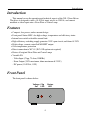
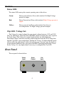
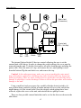
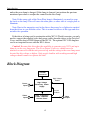
Neon Lamp Driver
Model NE-1
User and Technical
Manual
Copyright 2008-9 Aurora Design LLC.
Revision 1.2
10 February, 2009
All specifications subject to change
www.tech-retro.com
Introduction
Introduction
This manual covers the operation and technical aspects of the NE-1 Neon Driver.
The driver is designed to take a 10-20Vdc input, raise it to 350Vdc, and current
modulate a video input onto a Neon Plate or Crater Lamp.
Features
• Compact, low power, surface mount design
• Front panel Status LED’s for high voltage, temperature and efficiency status
• Internal user switch selectable current limit
• High efficiency switching supply generates 350V open circuit, and 66ma @ 250V
• High voltage, current controlled MOSFET output
• Over-temperature protection
• Direct connection to WC-01 (WC-01D option not required)
• Drives all original Neon Plate and Crater Lamps
• Versatile I/O:
- Video Input (1Vpp, 75 ohm, 500KHz)
- Neon Output (350V maximum, 66ma maximum @ 250V)
- DC power (10-20Vdc, 19W)
Front Panel
The front panel is shown below:
Voltage Clip
Set
LED
Status
LED
3
Introduction
Status LED:
The status LED conveys the current operating state of the driver.
Green:
Driver powered but no Neon cable attached. No High Voltage
present at output.
Red:
Driver Powered and Neon cable attached. High Voltage present at
output!
Yellow:
Driver powered and Neon cable attached, but driver is
over temperature. No High Voltage present at output.
Clip LED / Voltage Set:
The Voltage Set control adjusts the open circuit voltage between 115V and 350V.
The Clip LED shows when the Power MOSFET output is clipping the video signal to
the Neon Lamp. The Voltage Set control should always be set to minimum
(maximum counter clockwise) and then adjusted upwards until the Neon Lamp fires,
and the Clip LED is just extinguished. Turning the Voltage Set higher than this point
will not affect the performance of the driver in any way, but may cause the driver to
go into thermal shutdown due to the power MOSFET operating inefficiently. Never
set the Voltage Set any higher than is necessary to extinguish the Clip LED.
Rear Panel
The rear panel is shown below:
Video
Input
Neon
Output
4
Vdc
Input
Introduction
Video Input:
This RCA or BNC connector provides the video input to the driver. This input is
terminated into a 75 ohm load. The input accepts a 1Vpp video signal. This signal
should be DC coupled, and contain only the luminance information. This means there
should not be any sync or chroma information in this signal. Black should be at 0.0V
and peak white should be at 1.0V. For complete information about the characteristics
of this output, please refer to the Specifications section found later in this manual.
Neon Output:
The 3 pin Mini-DIN Neon Output connector connects the driver to the neon lamp.
One pin has the high voltage signal on it, one pin has the grounding current signal,
and one pin is ground. The high voltage and current signal are wired to the neon
lamp using wire rated for at least 350V. The ground signal is supplied only if a
shielded cable is used, but is normally left unconnected. Since the cable will be
carrying a high voltage, high frequency signal, it should be of a low capacitance type.
While a higher capacitance cable can be used, a fair amount of power will be wasted
in this capacitance and not make it to the neon lamp.
Caution! Because this driver has the capability to generate up to 350V and up to
66ma it can be very dangerous. The Neon Output Connector should never be
attached or removed with the unit powered up, and the wiring to the neon lamp must
be rated for this voltage or higher. Only people familiar with working around high
voltages should connect or operate this unit!
Power:
The driver requires a power source of between 10 and 20 volts DC at 19W
maximum. The exact amount of power required depends on the internal current limit
settings, and the operating voltage of the Neon Lamp. This power can be supplied by
an optional cable connected to the Switched Power Output on the WC-01 World
Converter. The unit has a fused input, so it will not be damaged by reversal of
polarity, or over voltage, but it will blow the fuse. The unit uses a standard 2.1mm X
5.5mm, center positive, coaxial power connector as found on most consumer
electronic equipment.
Internal Options
The internal Options switch is shown below:
5
Introduction
Back of unit
(Connectors)
Front of unit
(LEDʼs, Volt Set)
S1
Clip
LED
ON
1 2
Volt
Set
Option
Switch Status
LED
The internal Option Switch S1 has two controls allowing the user to set the
current limit of the driver. In order to change the switch settings, the cover must be
removed from the unit. To do this, first remove all cables from the unit, including the
power cable. Place the unit on it’s top, and remove the two, small phillips screws
from the bottom. Flip the unit back over, and remove the top.
Caution! In the subsequent steps, make sure you are touching the outer metal
ring on the phono connector to discharge any static electricity that may be present
before proceeding. There are static sensitive devices inside the converter that can be
damage if subjected to a static discharge. Failure to follow this procedure will result in
damage to the unit!
Using a small tool such as a paper clip, carefully slide the desired switch to it’s
new position being careful to not put an undue amount of force on the switch that
might damage it or the circuit board. Once the desired switch settings have been
achieved, replace the cover on the unit, and reinstall the two phillips screws.
There are four possible current limits that can be set for the driver as shown in the
table below:
6
Introduction
SW1
SW2
Switch position
OFF
OFF
ON
ON
OFF
ON
OFF
ON
25ma current limit
40ma current limit
50ma current limit
66ma current limit
These switches should be set to the current rating of the neon lamp being used. If
the rating of the lamp is unknown, it’s better to use a lower setting although this will
create a dimmer image.
Operating Modes
The video supplied to the driver is of a standard 1Vpp signal driving into a 75 ohm
load. It does differ however from normal composite video as it should only contain
the luminance information, and not contain any sync or chroma data. This data would
end up in the neon image and spoil the quality. The video should be DC coupled to
the driver with 0.0V representing black, and 1.0V representing peak white. The input
is automatically clamped at 1.2V and will not allow a higher level signal through. This
is required to limit the current, and potential damage to the neon lamp.
Before powering the unit up, the Voltage Set control should be turned maximum
counter clockwise. This will force the high voltage supply to a minimum voltage.
When power is applied to the driver and no neon cable is attached, the Status LED
will show green. This signifies that the unit is powered, but no high voltage is being
generated. When a neon cable is attached, the driver will sense this, and enable the
high voltage supply. The Status LED will then show red to signify that high voltage is
being generated, and care must be taken. If at anytime during operation the neon
cable is removed, the Status LED will return to green, and the high voltage supply
will be disabled.
With the unit powered, a neon lamp attached, and a video source that meets the
requirements as described in the Specifications section of this manual, the Voltage Set
control can be adjusted for normal operation. Starting with the control maximum
counter clockwise, the neon lamp may or may not be lit. Slowly turn the control
clockwise until the neon lamp is lit, and the Clip LED is completely turned off. This
will set the operating point of the current driver to it’s most efficient.
While no harm will come to the driver or the neon lamp if the Voltage Set control
is advanced to far, it will waste power, and may cause the driver to go into thermal
shutdown. If the driver does go into thermal shutdown, the Status LED will show
yellow, the high voltage supply will be disabled, and you will need to wait for the
driver to cool off before it will resume normal operation. (If this happens, the Voltage
Set control should be readjusted as described above.) You do not need to remove
power or the neon cable during a thermal overload as the driver will protect itself and
will automatically return to normal operation when the internal temperature drops.
Once the Voltage Set, control is adjusted, it should not need to be readjusted again
7
Introduction
unless the neon lamp is changed. If the lamp is changed, just perform the previous
mentioned procedure to readjust the control for the new lamp.
Note: If the wrong side of the Neon Plate lamp is illuminated, you need to swap
the leads on the lamp. This will cause the other plate, or other side of a single plate to
illuminate.
Note: Due to the magnetics used in the driver, there may be a slight noise emitted
from the driver in sync with the video. This is normal in drivers of this type and does
not affect its operation.
If the driver is being used in conjunction with a WC-01 World converter, you only
need to connect the supplied video and power cables from the driver to the Switched
Power and Mechanical RGB Output of the WC-01. The optional WC-01D daughter
card is not required for use with the NE-1 driver.
Caution! Because this driver has the capability to generate up to 350V and up to
66ma it can be very dangerous. The Neon Output Connector should never be
attached or removed with the unit powered up, and the wiring to the neon lamp must
be rated for this voltage or higher. Only people familiar with working around high
voltages should connect or operate this unit!
Block Diagram
Thermal
Protection
High Voltage
Enable
Po wer
Input
High Voltage
Switching Power
Supply
Current
Foldback
Video
Input
High Frequency
Power MOSFET
Current Driver
8
Neon
Output
Introduction
Pinouts
Neon Output:
3
2
1
1 - High Voltage Power
2 - Current Output
3 - Ground
Specifications
Video Input:
Video Input:
1Vpp, 75 ohm impedance
Video Bandwidth:
500KHz -3dB
Neon Output:
Output Voltage:
adjustable from 115V to 350V open circuit
Output Current:
adjustable limit of 25ma, 40ma, 50ma and 66ma
Output Power:
16.6W (66ma @ 250V) maximum
General:
Dimensions:
2.60” X 2.60” X 1.00” (66mm X 66mm X 25mm)
Weight:
3.0oz (85g)
Power Requirements:
18Vdc typical, 10-20Vdc maximum
19 watts typical (full load)
Temperature Limit:
75°C rising trip point, 65°C falling reset point
Humidity:
20% - 80% non-condensing
Temperature:
10C - 40C ambient (50F - 104F)
9
Revision History
Revision History
Revision 1.2, 10 February, 2009:
1) Initial release.
Note: Hardware revision level can be found on bottom label of unit.
10