1
USERS MANUAL
LC24-300 COLOUR
QBF
80825595
VDE Statement
This device carries the VDE RFI protection mark to certify that it meets the radio interference requirements of the Postal Ordinance No. 243/ 1991. The additional marking
Wfg. 243/P” expresses in short form that this is a peripheral,device (not operable alone)
which only individually meets the Class B RFI requirements in accordance with the DIN
VDE 0878 part 3/ 11.89 and the Postal Ordinance 243/ 1991.
If this device is operated in conjunction with other devices within a set-up, in order to
take advantage of a “’General (Operating Authorization” in accordance with the Postal
Ordinance 243/ 1991. the complete set-up must comply with the Class B limits in accor
dance with the DIN VDE 0878 part 3/11.89, as well as satisfy the preconditions in
accordance with 52 and the prerequisites in accordance with 53 of the Postal Ordinance
243/ 1991.
As a rule. this is only fulfilled when the device is operated in a set-up which has been
type-tested and provided with a VDE RFI protection mark with the additional marking
“Vfg 243”.
Machine Noise Information Ordinance 3. GSGV. January 18, 1991: The sound pressure
level at the operator position is equal or less than 70 dB(A) according to 1S0 7779.
Bescheinigung
des Importers
Hiermit wfrd bescheinigt. dafi cfer
COMPUTER DRUCRER Q24260
in Ubereinstimmung mit den Bestimmungen der
VDE 0878 3/22.89. EN 55022; 1987, BMPT Vfg. 243/1991 und 46/ 1992
funk-entstort ist
Dem Zcntralamt fur Zulassungen im Femmeldewesen wurde das hwerkehrbringen
dieses Gerates angezeigt und die Berechtigung zur Uberpfifung der Serie auf die Einhal
tung der Bestimmungen eingeraumt.
Star Micronics Deutschland, GmbH
WesterbachstraJe 59. D-60489
Frankfurt, Germany
The aboue statements apply only to printers marketed in Germany
Trademark acknowledgments
LC24-300 Colour, LC24-200 Colour, LC24-200, SF-1ODW, SPC-8K: Star Micronics Co
Ltd.
L9S5fY, L9S60, LQ105O, L9106O: Seiko Epson Corporation
IBM PC, IBM Proprinter X24E, IBM Froprinter XL24E, IBM Proprinter X24, IBM
Proprinter XL24: International Business Macbines Corporation.
TrueType Macintosh: Apple Computer Inc.
PostScript: Adobe Systems Incorporated.
MS-DOS, Microsoft Windows, Windows 3.1: Microsoft Corporation
Grappler: Orange Micro lnc
Notice
●
.
.
.
All rights reserved. Reproduction of any part of this manual in any form whatsoever.
without STAR’s express permission, is strictly forbidden.
The contents of this manual are subject to change without notice
Afl efforts have been made to ensure the accuracy of the contents of this manual at
the time of printing. However, should any errors be found. STAR would greatly
appreciate being informed of them,
The above notwithstanding, STAR can assume no responsibility for any errors in
this manual,
@ Copyright 1993 Star Micmnics Co., Ltd
I
Guide to this manual
Even though the LC24-300 Colour is basically a very
simple printer to use, it is also capable of many complex
functions. We have grouped this manual into two main
sections, divided into seven chapters and an appendix.
For normal everyday use, you may never need to refer to
Section II at all. We strongly recommend however that
you read through Section I (Chapters 1, 2 and 3) before
connecting and using the printer for the first time.
Guide tothismanuai....
..........................................................................
iii
Introduction
1
Features ......................................................................................................... I
Parts ................................................................................................................4
7
Choosing a place for the printer ......................................................... T
Unpacking the printer ............................................................................ 8
Setting up your printer ..................................................................
9
Unpacking and setting up
Fitting the platen knob. ............................................................................ 9
Removing the front cover ...................................................................... 7~
Installing the ribbon cartridge .............................................................. 70
Removing the ribbon cartridge ............................................................ 72
Installing the roller unit. ......................................................................... 72
Removing the roller unit ........................................................................ 73
Replacing the front cover ......................................................................73
Installing the paper guide ...................................................................... 74
Installing the mute cover ....................................................................... 74
Connecting the printer to the computer .......................................75
Setting up your printer with your computer .............................. IT
Setting up with MS-DOS ........................................................... ...........77
MS-DOS ..................................................................................................... 17
MS-DOS application software ................................................................ 17
Setting up the printer in Windows ..................................................... 79
Installing TrueType fonts (for Windows) ............................................... 27
Selecting different fonts .......................................................................... .22
Using your printer
Loading paper ...........................................................................
23
......23
Adjusting the print gap ..........................................................................24
Loading cut sheet paper ............................................ ...........................26
Loading and parking fanfold paper ...........................................,.........27
Loading paper from the rear of the printer .............................................28
Loading paper from the bottom of the printer ......................................30
Parking paper ............................................................................................ 31
Unparking the paper ................................................................................32
Using the control panel
33
Ready and not-ready modes ................................................................. 33
Pageiv
Pausing printing ....................................................................................... 33
Feeding paper through the printer .....................................................34
One line or several lines at a time. ............................... ......................... 34
A page at a time ....,.... L................................... ......................................... 34
Individual form tear-off ...........................................................................34
Loading paper ..........................................................................................35
Micro-feeding paper (backwards and forwards) ...................................35
Setting the top of a form ....................................................................... 35
Changing the autoloading position ....................................................36
Eject and park ........................................................................................... 37
Quiet printing ........................................................................................... 37
Changing the way your printout looks ............................................. 38
Selecting
Changing
Changing
Selecting
the
the
the
the
different fonts ................................................................... 38
pitch of the font ............................................................... 39
zoom size .......................................................................... 40
print color .......................................................................... 41
Controlling the printer’s memory ....................................................... 42
Saving Macros .......................................................................................... 42
Re-moving the macro ............................................................................... 43
Clearing the buffer ...................................................................................43
Setting the printer back to default settings ..........................................44
Locking the printer .................................................................................. 45
Font
Font
Pitch
Pitch
Pitch
Pitch
lock ................................................................................. .................45
unlock ............................................................................................... 45
lock. ................................................................................................. 45
unlock .............................................................................................. 46
and font lock ...................................................................................46
and font unlock...............,, ...............................................................46
Test printing .............................................................................................47
Short test. ................................................................................................. 47
Long test. .................................................................................................. 47
print area test mode ................................................................................ 48
Hexadecimal dump mode ....................................................................... 49
Adjusting the dot alignment ................................................................50
Electronic DIP switches ........................................................................ 5.2
Using the Electronic DIP switches ......................................................53
Banks and numbers .................................................................................53
Selecting the switch bank. ...................................................................... 53
Selecting the switch number .................................................................. 54
Changing a switch’s value ...................................................................... 54
An example..., ........................................................................................... 54
Exiting Electronic DIP Switch mode ......................................................54
What you can change with the Electronic DIP Switch mode ...... 55
Meanings of the switches ..................................................................... 56
A 1- Emulation ..........................................................................................56
Pagev
I
A2-Auto
Emulation Change (AEC) mode. ............................................ 56
A3-RAM
usage .......................................................................................57
A4-Colorand
zoom ..........................................................................,.....57
A5-Auto
LF with CR.. ............................................................................. 57
A6 - Auto sheet feeder. ........................................................................... 57
B1 - Graphics direction ............................................................................57
B2 - Paper-out . . . .. ... . . .. .. . .. . . .. .. ...................................................58
B3 - Tear-o if............. ................................................................................. 58
B4 - Reserved ...........................................................................................58
B5 and B6 - Multi-part mode .................................................................. 58
Cl and C2 - Print mode ........................................................................... 59
C3 through C5 - Page length ................................................................... 59
DI - Character table .................................................................................59
D2 through D4 - character code tables ..................................................60
D5 -CR centering .....................................................................................61
El through E5 - LQ Font selection ........................................................ 61
FI - Electronic DIP switch settings ......................................................... 62
Optional accessories
63
Accessories available............................,..,............................................. 63
The SF-IODW ............................................................................................ 63
Unpacking ................................................................................................. 63
Installing the SF-1 ODWASF......... ...........................................................64
Using the SF- IODW........... ................... . .. . . . ..... .. . . ..... . .. . .............65
The SPC-8K serial/parallel converter .................................................. 67
Baud rate. ............................... ... . .. . .. . . . .... .... .. . .... .. .... . .. . ...... 68
Number of bits in a word ........................................................................ 68
Parity .............................................:.. .................................... ..................... 68
Handshaking ........................................ ....................................................69
Connecting the SPC-8K converter ..........................................................69
Using the SPC-8K......... ............................................................................70
The serial connector on the SPC-8K......... .............................................. 71
Setting up an MS-DOS computer ........................................................... 72
Setting up a Windows computer...........,.........,...
................................... 73
Troubleshooting
75
Common problems and solutions ................................................... 76
Power switch is on, but POWER indicator is neither lit nor flashing.. 76
Printer sounds as if it is printing, but is not . . . . .. . . .. . . . .... . . ......76
Printing is weak.,.....,.......,......,.............
.....................................................76
Printer tests work, but printer will not print out data from attached
computer ... . . . .. .. . . . . . . .................................... . .... .. . . . . . . .. 77
Font selection changes unexpectedly ...................... . . .. . .... . .. .. .. . 77
Printer will not feed paper properly .......................................................78
Pagevi
The printer will not print in color ........................................................... 78
Line spacing is incorrect.... ...................................................................... 79
Over-printing occurs ................................................................... .........79
Incorrect number of lines per page ........................................................80
Malformed text or graphics . .................................................................80
Poor printing quality.... ............................................................................ 80
Forms are smudged ....................... .......................................................... 81
Printing is too dark.. ................................................................................
:!
Printer case is hot. .................................................................
............. ................................... 82
Printer makes excessive noise..............,
Printer prints beyond the edge of the paper .........................................82
Left margin moves towards the right during printing ......................... 83
Some incorrect characters are being printed ........................................84
Printer behaves erratically ........................ .............................................85
Printing ceases.... ..................................................................................... 85
Display messages (non-error) ..............................................................85
Display messages (error) . .................................................................... 87
Beep tones ................................................................................................. 88
Checking system so fiware settings ............................................. W
In Windows ............................................................................................... 89
In MS. DOS.. ............................................................................................... 90
Software commands
91
Introduction ................................................................................................ 91
Font control commands ........................................................................ 93
Character set commands ...................................................................... 98
Character size and pitch commands ................................................ 702
Vertical position commands .............................................................. ~70
Horizontal position commands .......................................................... 777
Graphics commands.... ......................................................................... 127
Download character commands ....................................................... 725
Other printer commands ... ................................................................. 729
Appendix
Specifications
135
.. ..................................................................................... 135
Parallel interface.. .................................................................................. 140
Character sets. ........................................................................................ 147
Standard character set #2... ................................................................ 742
International’ character sets. ............................................................... 744
IBM character set #2 ............................................................................. 745
Code page #437 (U. SEA.).......... ..........................................................
145
Code page #’850 (Multi.lingual) ............................................................. 747
Pagevii
Code
Code
Code
Code
page
page
page
page
#860
#861
#863
#865
(Portuguese) ............................................................... 148
(Icelandic) .............................................’. ...................... 149
(Canadian French) ...................................................... 150
(Nordic) ....................................................................... 151
Character set #l ..................................................................................... 752
IBM special character set................................,..... ............................... 753
Pageviii
Glossary
155
Index
167
Costumer service information
171
I
Chapter1
Introduction
Thank you for buying a STAR LC24-300 Colour printer.
We are confident that it will provide you with years of
reliable, high-quality printing. We think we have made
the LC24-300 Colour one of the fastest, quietest, and
easiest to use dot matrix printers ever. We hope you
agree with us.
Features
color
You only need to add a color ribbon cartridge
to print vibrant, full-color documents. You
can choose from up to 256 colors, depending
on your computer software.
Fu&:
The LC24-300 Colour speeds through drafts
at 360 characters per second (15 pitch).
When printing in its 360 dpi letter-quality
mode (that’s more dots per inch than some
laser printers!), it turns out beautifully-finished work atup to 100 characters per
second.
Easy to use: With clearly labeled buttons, an informative
LCD screen, and easy paper loading, the
LC24-300 Colour can be used by anyone,
even without previous computer or printer
experience.
With the LC24-300 Colour’s Electronic DIP
Switch feature, you can change the printer’s
default power-on settings from the front
panel.
Page1
LCD screen: You can see your printer’s settings at a glance
by looking at the informative LCD screen. It
shows what font you are using, how big it is
(the font pitch) and other useful information
(this feature does not apply when you use the
printer with Windows 3.1 or later).
Fonts:
The LC24-300 Colour is a multi-font printer,
which means that it can print text in a variety
of different type styles (fonts)—10 in all.
These include:
Draft
Samerif
Prestige
Roman
Courier
ORATOR
Sdpk
Orator-2
H-Go t h i c
SLQ Roman
You can print these fonts in different styles,
such as emphasized, bold, shadow, and outline, as well as being able to change the size
of the font.
Graphics:
The advanced 24-pin print head can print up
to 360 dots per inch (and in color too!) making it an ideal printer for graphics programs,
and for programs running under Windows
3.1 and later.
Zooming:
You can print documents at 50V0or 67V0of
their actual size. As a result, you need only
use a single sheet of paper to print large documents, such as spreadsheets.
Paper t~pes: You can print on a wide variety of different
paper types and sizes; from fanfold computer
paper, to single sheets and stationery, to
multi-part forms. Even when fanfold paper is
loaded, the LC24-300 Colour allows you to
print on single sheets, saving you time and
Page2
effort. A tear-off function allows you to tear
off single printed fanfold paper sheets from
the printer without wasting paper. You can
feed fanfold paper from either the rear or the
bottom of the printer.
An optional automatic sheet feeder is also
available, which holds up to 50 sheets of
paper.
Compatibility By emulating the industry-standard Epson
and IBM printers, the LC24-300 Colour
allows you to print just about anything your
computer software can generate. The NEC
graphics command set is also supportted for
even better graphics compatibility.
The Automatic Emulation Change feature
means that the printer can automatically
change to the appropriate printer emulation
for the application software, depending on
the data received.
Special drivers and scalable fonts are
included to allow you to produce high-quality
printout from Windows 3.1 and later applications.
Page3
Parts
This is what your new printer looks like. These diagrams
may be useful in the next few sections to identi& the different parts mentioned.
front
er
b
power
h)
The printer (with interface cable connected)
peperkh
edjustm
ribbon
ver
The printer with the front and rear covers removed and no interface
cable connected
Page4
Parts - an explanation
The paper guides hold single sheets and sets their position so that they are fed into the printer correctly.
The paper entrances are where paper feeds into the
printer. There is one for single sheets, and two for computer (fanfold) paper—rear and bottom.
The release lever grips single sheets as they are fed in.
The lever should be pushed towards the back of the
printer to hold single sheets properly, and released
(pulled forward) when fanfold paper is in use.
The platen knob lets you feed paper through the printer
manually. Usually, though, you will find that the
[PAPER FEED] button (see “Feeding paper through the
printer” on page 34) is the most efficient way of doing
this.
The front cover protects internal components and
reduces printing noise.
The mute cover further reduces printing noise.
The display screen shows information about the printer’s current setting.
The control panel has buttons to control the printer.
The power switch turns the printer on and off.
The interface connector accepts the cable connector
that links the printer to the host computer.
The print head transfers the image to the paper.
The ribbon cartridge contains the ribbon which the
head uses to mark the paper.
The paper thickness adjustment lever lets you adjust
the position of the print head for different paper thicknesses and for multi-part forms.
The roller unit helps to grip paper and pull it through
the printer.
Page5
The tractor unit grips the sides of fanfold computer
paper. When you use the tractor unit, the tractor covers must be closed.
Page6
I
Chapter2
Unpacking and
setting up
Choosing a place for the printer
Before you start unpacking and setting up your printer,
make sure that you have a suitable place to put it. By a
“suitable place”, we mean:
●
A firm, level surface where the printer will be stable,
and vibration-free.
●
Away from any heaters.
●
Away from direct sunlight.
●
Not in an excessively humid area.
●
Somewhere that is clean, dry and dust-free. Basically, computer equipment works best in the same
kind of temperature and humidity as you do.
●
Allow 6“ (15cm) of free space either side of the
printer and adequate space for paper behind the
printer, if you want to use fanfold (computer) paper.
●
If you want to use the bottom feed for fanfold (computer) paper, you should locate the pile of paper at
least one page length (about 12” (30cm)) below the
printer.
●
Make sure the printer is connected to a steady
power supply. It should not be on the same electric
circuit as appliances like copiers or refrigerators
that cause power spikes and surges.
●
Use a power supply of the correct voltage as specified on the printer’s identification plate.
Page7
I
Unpacking the printer
As you unpack the printer from the box, make sure that
you have all the following items:
-4
2 Printer driver
and font disk
m
A’
\\&2\
guide
If any of these are missing, please contact your supplier.
Optional accessories that you may have purchased are:
●
Serial-Parallel converter (SPC-8K)
●
Automatic sheet feeder (SF-10DWI
For details of how to install these optional accessories,
see Chapter 5.
You will also need a cable to connect the printer to your
computer (available separately). For IBM or IBM-compatible computers, this will generally be a parallel cable,
with a 25-pin,‘D’ connector at one end and a 36-pin
Arnphenol-type (Centronics) connector at the other end
(a “Centronics” printer cable). This cable should be no
longer than about 6’ (2m].
Page8
If your computer has no parallel port available, you will
need to use the Serial-Parallel converter (SPC-8K) and a
cable to connect your computer to the printer. See “The
SPC-8K serial/parallel converter” on page 67 for full
details.
Setting up your printer
Remove the printer and all supplied parts from the
packing material. Put the printer on the place you have
prepared for it. Save the packing material and carton in
case you need to move the printer in the future.
Fitting the platen knob
This knob is packed into a recess of the packaging material in the printer box.
To. fit the knob, rotate the knob on the shaft (lining up
the flattened side of the shaft with the flattened part of
the hole on the knob). After you have lined up these flattened sides, push the knob firmly onto the shaft.
Page9
I
Removing the front cover
You will need to remove the front cover (the smoked
plastic cover on the top of the printer) to install and
change ribbon cartridges. Lift the cover from the rear
using the grips on the sides, then lift up to remove the
cover from the body of the printer.
Installing the ribbon cartridge
You have the choice of using a color or a black ribbon
with the LC24-300 Colour. Both ribbons are installed
and removed in the same way.
●
Take the slack out of the ribbon by turning the knob
on the ribbon cartridge clockwise (as shown by the
arrow).
Page10
Place the cartridge on the cartridge carrier inside
the printer. Make sure that the ribbon is between
the print head and the print head shield. Press the
cartridge so that it “clicks” into place. If the cartridge does not “click” into position on both sides,
you may need to turn the cartridge knob about 1/4
of a turn clockwise.
●
Once the cartridge is in the carrier, tighten the ribbonagain by turning the cartridge knob clockwise
(about 1/2 a turn). Check once more to make sure
that the ribbon is between the print head and print
head shield (if it isn’t, take the cartridge out, and try
again).
Page11
Removing the ribbon cartridge
●
To remove the ribbon cartridge, press the cartridge
grips inward and lift the cartridge upward out of the
printer.
Installing the roller unit
●
Open the rear cover by pushing the cover grips
backward and upward.
●
●
Pick up the roller unit so that the small illustration
is on top of the roller unit, and the smoked plastic
side (with six small black rollers) is facing you.
Hold the roller unit so that the top is tilted slightly
away from you.. Slide the hooks on either side of the
back of the roller unit over the platen (the large
black roller) and under the silver bar behind and
above the platen. The hooks should both be between
the metal plates at either end of the silver bar.
Page12
●
Push the front of the roller unit down firmly, so that
the unit “clicks” into place. If it does not fit properly,
remove it and try again.
Removing the roller unit
●
Pull both gray locking tabs towards you and lift the
front of the roller unit slightly to remove the roller
unit. Pull the roller unit out of the printer towards
you.
Replacing the front cover
Once you have fitted the ribbon and roller unit, you
should replace the front cover.
Note:
●
Even though you can operate the printer with the front cover
removed, we do not suggest that YOUdo this. The Printer will
be noisy and it is also possible to drop things into the printer,
which may damage the mechanism.
Hold the cover by the grips, so that the griPs are on
the side of the cover furthest from you. Tilt the top
of the cover towards you a little.
●
Insert the tabs into the slots in the case.
●
Lower the rear of the cover into position.
Page13
1’
Installing the paper guide
You can set the paper guide on the LC24-300 Colour in
one of two positions: horizontal for fanfold paper and
vertical for single sheets.
●
●
●
Hold the paper guide, either horizontally, or vertically, depending on the type of paper used.
Fit the tabs into the slots on the printer body to
install the paper guide.
Make sure the guide is firmly in position.
Installing the mute cover
The mute cover helps reduce the noise from your printer
when you are printing.
Page14
●
Hold the mute cover upright so that the ridges on
the cover are towards you and at the top.
,0
●
Slide the left tab on the mute cover into the left hole
on the front cover.
●
Drop the right tab on the mute cover into the right
slot on the front cover. Close the mute cover by
swinging it down.
Connecting the printer to the computer
We assume here that you are connecting the printer to
an IBM or IBM-compatible computer, using the parallel
interface. If you are connecting using a serial interface,
or connecting to any other type of computer, read Chapter 5.
Note:
Before connecting or disconnecting the printer and the computer, make surethatthe powerto boththe printerandthe
computeristurnedOFF.Ifthe poweris on whenyou makeor
breaktheseconnections,
thereis a riskthatyou will damage
thecircuitryof the computerand/or the printer.Repairscan
be expensive!
Page.15
●
Press the cable plug into the printer socket:
●
Clip the cable into the socket using the wire clips on
either side of the socket.
●
Connect the ‘D’ connector on the other end of the
cable to the parallel (printer) port on your computer.
This will probably be labelled Printer, Parallel,
PRN, LPT1 or something similar. Refer to your computer’s instruction manual for details of how to
secure the cable.
●
Now you can turn on your printer and computer.
Page16
I
Setting up your printer with your computer
In this section, you will learn to set up your printer with
two different computer environments: MS-DOS or
Microsoft Windows 3.1 (or a later version of Windows). If
your computer uses a different operating system, you
should refer to Chapter 5 for details of setting up your
printer. Refer to your computer operating system manuals for details of configuring the operating system.
Setting up with MS-DOS
Every program that you use with MS-DOS must be
“told” separately what printer is connected to your computer. This is usually done in an INSTALL or SETUP program or menu option within your application software
(word-processor, spreadsheet, or whatever).
Look for an option called “Add printer”, “Install printer”
or “Configure printer” in your application software. If
you can’t find this option easily, read your software
manual to find out how to do it.
MS-DOS
MS-DOS needs no specific commands to make it work.
To test that the printer is connected properly to the
computer, try entering the following command from the
c> prompt:
PRINT \AuTOExEC.BAT (lZ?RR)
If the computer answers with:
Name of list device [PRN]:
hit [~]
again. The printer should then print the
contents of the file AUTOEXEC. BAT. If the file
AUTOEXEC. BAT does not exist, you will get an error message on your computer. Most MS-DOS computers do
have a file called AUTOEXEC. BAT,however.
MS-DOS application soiltware
The LC24-300 Colour can emulate (pretend to be) a
member of one of two printer families: Epson or IBM.
Page17
I
When you open the box containing your LC24-300
Colour, the printer is set to Epson emulation. This is
commonly supported by most software. If your software
package gives you a list of printers to choose from,
choose one printer from the following list (in order of
preference):
Star LC24-300 Colour
Star LC24-200 Colour
The shaded printers are not color printers, so if you
select one, you will not be able to print in color.
If none of the printers above is listed, choose one of the
following, in order of preference:
These two printers are not color printers, so if you select
either, you will not be able to print in color.
Note:
Theprintersin shadedboxesdo not supportcolor. If you
selectthem,alloutputwill be in blackonly,regardless
of the
ribboninstalledor the softwaresettings.
If you select either of these IBM Proprinter models, you
may need to change your printer emulation.The Auto
Emulation feature (page 56) of the LC24-300 Colour
should take care of this for you. See “Al- Emulation” on
page 56 on how to change the emulation if you have
trouble with your printer.
Page18
If your software doesn’t list printer names, but asks you
questions about your printer, you should answer “Yes”
to the following two questions:
●
“Can your printer perform a backspace?”
●
“Can your printer do a hardware form feed?”
The answers to any other questions are not so important. Answer these using the default settings in the
software.
When you’ve set up your software, try a few test prints,
using features like bold, italic, etc. to see how it works. If
you find you have problems making your software work
with your hardware, the best source of help is usually
your software supplier.
Setting up the printer in Windows
The LC24-300 Colour is ideally suited for use with computers running Microsoft Windows system software. It
works best with Windows version 3.1 or later. If you are
running an earlier version of Windows, we recommend
you upgrade your computer to the latest version. In particular, this will allow you to use the 15 TrueType fonts
included on the floppy disk packaged with this printer.
To use the printer with Windows, you need to install a
file known as the printer driver file onto your computer.
This file is supplied on the floppy disk packaged with the
printer.
The following description assumes that you are using a
mouse. (Click and doubZe-cZick
refer to the action of
using the mouse to point at an item with the on-screen
pointer, and then pressing the left mouse button either
once, or twice in quick succession.)
If you are not using a mouse, you can still carry out the
installation. Refer to the Microsoft Windows User’s Guide
to find out how to use the keyboard instead of a mouse
to operate Windows.
Page19
I
To install the printer driver under Windows 3.1, do the
following:
●
Turn on the printer and start up your computer.
●
If Windows does not start up automatically, type
WIN and then press [ZN7EY]or [~).
●
Double-click the Control Panel icon in the Main window.
●
Double-click the Printers icon
●
If you have never previously installed a printer on
your system under Windows, a list of supported
printers is displayed. (If you have already installed
one or more printers, select the Add button to display the list of supported printers.)
●
Click on InstaZl Unlisted or Updated Printer in the
list, so that this option is highlighted.
●
Click Install. A window prompts you to put in the
floppy disk supplied with the printer.
Insert the disk with the printer driver file on it and
click OK. A new list of printers appears.
(If you have inserted the disk into a drive other than
drive A, you must type in the drive letter followed by
.a colon and a backslash, e.g. “B:\“before selecting
OK.)
●
Select LC24-300 Colour from the new list of printers.
●
Click OK. The ,list of installed printers appears,
including the LC24-300’ Colour.
Click on Set As Default Printer.
Click on CZoseto return to the Control Panel window.
For instructions on how to configure the printer, see the
section of the Microsoft Windows User’s Guide called
Control Panel.
Page20
If you cannot print from your applications programs
after installing the driver, refer to the section “In Windows” on page 89.
Note:
Unlessthe userchoosesa differentprinterfrom withinthe
application,
Windowsapplications
alwaysprintto the currentlyselecteddefaultprinter.
Installing TrueType fonts (for Windows)
To install the TrueType fonts that are on the floppy disk
accompanying this printer, follow the procedure below.
Double click the Control Panet in Windows.
Double click on Fonts. The Fonts dialog box appears.
Click Add. The Add Fonts dialog box appears.
Insert the disk in your computer’s floppy disk drive.
Select the drive by letter (this is usually “A:”, sometimes “B:”). The names of the fonts stored on the
disk are displayed in the List of Fonts window. Each
font name is followed by the word “TrueType”
Select the fonts you wish to install. If you want to
install all of them, click SelectAll.
Click OK. The Fonts dialog box reappears and installation is earned out. The names of the newly
installed fonts are automatically added to the
Installed Fonts list.
Within your applicationprogram, select Printer Setup
from the application’sIWe menu, and reselect the
printer.The applicationcan now display text on-screen
and print text on your printer using the new fonts.
Note:
TheTrueType
fontsthataresuppliedcanonlybe usedon IBM
PCcompatiblecomputersrunningWindows3.1or higher.
Page21
I
Selecting different fonts
If you are running applications software under
Windows, you will select fonts from within your application (refer to your application’s manual for details).
Your application software manual will tell you the various ways in which you can type-set your text on-screen
so ‘that it is ready to print out on the printer.
Your Windows system already includes several fonts,
such as Arial, Times New Roman and Symbol. You can
also use the 15 True~pe fonts included with the
printer. If you have installed Adobe me Manager software on your computer, you can also display and print
Adobe PostScript fonts.
Page22
Chapter3
Using your printer
Loading paper
The LC24-300 Colour can print on a variety of paper
types, as explained below:
Cut sheet paper
The LC24-300 Colour can use single sheets of paper (cut
sheets) or letterheaded stationery. Use the friction feed or
the optional SF-1ODWautomatic sheet feeder.
Fanfald paper
It can also accept fanfold (continuous) computer stationery. Fanfold stationery has the sheets joined together,
with perforations between sheets, and holes (“sprocket
holes”) along each edge to help the printer grip the
paper. You should not print too close to the sprocket
holes. Otherwise, you run the risk of jamming the paper
in the printer.
Multi-part
forms
You can print continuous multi-part forms which are
either carbon backed or pressure-sensitive carbonless
(NCR), with up to five copies (including the top copy). If
you use multi-part forms, we suggest that you feed them
through the bottom paper feed slot, as this will help to
prevent premature separation of the forms. There
should be a difference in thickness of not more than
0.05mm between the side edges.
Note:
Ifyou usemulti-partsets,setup the Multi-Partsettingusing
theElectronic
DIPswitchesasdescribedin “B5andB6- Multipartmode”on page58.
Page23
Where you can print on each kind of paper
Single sheets
Fanfoldforms
5 mm
5 mm
18 mm
5 mm
Perforation
Bottom of
Form
.
0
81 mm
o
0
If you print outside these limits, you run the risk of
damaging the printer mechanism (and tearing the paper
or jamming it as it goes through the printer).
Adjusting the print gap
Note:
Important.Ifyou do not adjustthe printgapproperly,you run
the riskof shorteningthe lifeof the printhead.
Different paper thicknesses need a different gap
between the print head and the paper. The LC24-300
Colour allows you to make six different settings, using
the adjustment lever at the left of the printer. If you
push this lever towards the back of the printer, the gap
Page24
is narrowed (thin paper), and if you pull it towards the
front, the gap is widened (thick paper).
As you move the lever, you can feel it click between the
six different positions. Position number 2 (starting from
the rearmost position) is the one you will generally use
for single sheets of paper (fanfold or cut sheet). Here is a
table for the adjustment lever when you use multi-part
sets.
Thickness
Recommended
lever position
(1 = rearmost)
Paper
type
Weightof each
sheet
Sincjle
14 to 24 Ibs (52 to 90 gsm)
007to 0.12
2 or 3
2-part
11 to 14 Ibs (40 to 52 gsm)
0.12 to 0.14
2 or 3
3-part
11 to 14 Ibs (40 to 52 gsm)
0.18 to 0.21
3 or 4
4-part
11 to 14 Ibs (40 to 52 gsm)
0.24 to 0.28
4 or 5
5-part
11 to 14 Ibs (40 to 52 gsm)
0.30 to 0.35
5 or 6
Note:
Ifyou usemulti-partsets,setup the Multi-Partsettingusing
the Electronic
DIPswitchesasdescribedin “B5andB6- Multipartmode”on page58.
‘total‘n ‘m)
Page25
Loading cut sheet paper
This procedure shows you how to load cut sheet paper
using the paper guide. If you are using the SF- 10DW
automatic sheet feeder, please refer to “Using the SF10DW” on page 65.
. This is how cut sheet paper is fed through the printer:
. Make sure that the paper guide is in the vertical position. See “Installing the paper guide” on page 14.
. If no fanfold paper has been loaded, and no cut sheet
paper has been loaded, the display will show “PE”
alternating with the character pitch when the printer
is turned on. The printer will also beep.
. Make sure that the release lever is at the back position ( ? ).
. Adjust the left and right paper guides to the position
you want. Allow the paper to feed through the guides
smoothly, but without allowing it to move from side to
side while feeding through. A gap of less than a millimeter (0.04”) is ideal.
. Place a sheet of paper in the guides (upside down,
and printing side towards the rear of the printer), and
gently push it down between the guides until you feel
it stop.
Page26
●
Press the (SET/EJECT) button. This should make the
printer feed the paper round the platen until it is in a
position suitable for printing. The ON LINE indicator
should come on. If this does not happen, you have
probably not loaded the paper correctly. Take the
sheet out and try loading it again.
●
If the paper is at the wrong place to start printing (for
instance, if the address printed on the top of your letterhead takes up a lot of space), put the printer notready mode (press the [~]
button) and use the
micro-feed function, as described in Chapter 4.
●
You can now start printing.
Loading and parking fanfold paper
You can use fanfold paper up to 25cm (10”) wide with
this printer. You can feed this paper from the bottom or
the rear of the printer.
These are the ways in which fanfold paper is fed through
the printer:
Page27
I
Loading paper from the rear of the printer
Always load fanfold paper with the printer’s power
turned OFF.
●
Place the stack of fanfold paper behind and below the
printer.
●
Pull the release lever at the right of the printer
towards you ( n ). This releases the paper from the
platen and allows it to feed through the tractor rollers.
●
Open the mute cover and the rear cover
●
Grip the gray tractor position locking levers on both
sides of the tractor unit and rotate the tractor unit as
far as it will go (about 20 degrees) so that the top is
tilted slightly towards you:
●
Open the tractor pin covers and align the holes in the
fanfold paper with the pins on the tractor unit. You
will probably need to slide the tractor pin units left
and right to align the paper properly. Use the gray
locking levers on each tractor pin unit to allow the
unit to slide left and right along the rail. Remember to
Page28
lock each tractor pin unit in place again when you
have finished moving it.
“ “Close the pin unit covers after you have made sure
that the paper holes are properly lined up with the
tractor pins. If the holes and pins are not correctly
lined up, you may find that the paper tears and jams.
Note:
Ifthe paperistoo tightlystretchedor too loosebetweenthe
pin holders,the paperwilltearor jam asit isfedthroughthe
printer.Youmayneedto experimentto find the idealtension.
“ Close the rear and mute covers, and insert the paper
guide in the horizontal position. See “Installing the
paper guide” on page 14.
. When you turn on the printer (using the switch at the
front), the display will show “PE” alternating with the
character pitch. The printer will also beep.
●
Press the ISETIEJECT] button to load the paper into the
printer. The printer will go into ready mode.
. If you want to adjust the paper position, put the
printer into not-ready mode (use the [~]
button)
and use the micro-feed function (described in Chapter 4).
Page29
Loading paper from the bottom of the printer
Always load fanfold paper into the printer with the printer’spower turned OFF.
. Remove the front cover and the roller unit. See
“Removing the front cover” on page 10 and “Removing
the roller unit” on page 13 for details.
“ Grip the gray tractor position locking levers on both
sides of the tractor unit. Rotate the front of the tractor unit upward so that the top is horizontal.
s With a stack of fanfold paper below the printer, feed
the top sheet of the stack through the feed slot at the
bottom of the printer and pass it over the platen.
●
Open the tractor pin covers and align the holes in the
fanfold paper with the pins on the tractor unit. You
will probably need to slide the tractor pin units left
and right to align the paper properly. Use the gray
locking levers on each tractor pin unit to allow the
unit to slide left and right along the rail. Remember to
lock each tractor pin unit in place again when you
have finished moving it.
“ Close the pin unit covers after you have made sure
that the paper holes are properly lined up with the
Page30
tractor pins. If the holes and pins are not correctly
lined up, you may find that the paper tears and jams.
Note:
Ifthe paperistoo tightlystretchedor too loosebetweenthe
pin holders,the paperwilltearor jam asit isfedthroughthe
printer.Youmayneedto experimentto findthe idealtension.
●
Replace the roller unit (see “Installing the roller unit”
on page 12).
●
Replace all the covers that you have removed.
●
Turn on the printer.
●
Put the printer into not-ready mode (use the [~]
button) ‘ad use the [PAPER FEED] button to advance
‘the paper so that the print head is just below a perforation. Put the printer into ready mode again.
Parking paper
Paper parking allows you to print single cut sheets even
when fanfold paper is loaded. The fanfold paper is temporarily “parked” out of the way while the cut sheet is
fed through the printer.
Note:
Youcanonly usethe paper@rking functionwhenfanfold
paperis loadedfrom the rear.Youcannotuseit whenyou are
feedingfanfoldpaperfromthe bottomslot.
. The power should be ON. The release leaver should be
pulled forward ( ~ ) and the fanfold paper loaded.
. Put the printer into not-ready mode (use the [~]
button).
. Tear off the last page of the fanfold paper. If the paper
is not in a suitable position to be torn off, use the
[PAPER FEED) button to feed the paper forwards to a
suitable position.
Page31
●
●
Press the [SET/EJECT] button. The printer will feed the
fanfold paper back until it is out of the way.
Move the release lever to the back ( N ) position.
“ Place the paper guide in the upright position.
Load single sheets as described in “Loading cut sheet
paper” on page 26.
Unparking the paper
When you have finished printing on cut sheet paper and
you want to start printing again on fanfold paper, here’s
how you do it:
●
Remove any cut sheets which may still be in the
printer.
●
Place the paper guide in the horizontal position.
●
Move the release lever to the front ( D ) position. The
printer will beep if you move the lever while paper is
still loaded ready for printing.
●
Press the [SET/EJECT] button. The parked fanfold paper
will be fed into the correct position ready for printing
again.
Page32
I
Using the control
panel
Chapter4
The LC24-300 Colour control panel has five buttons,
which have white labels above them to indicate their primary functions. Other functions are available as alternative functions (labelled in brown) or by pressing
combinations of buttons (labelled in yellow).
ALT
MACRO
cOLOR
ZOOM
CLEAR
There are two indicators: the POWER indicator shows
that power is supplied to the printer. When steadily lit, it
means that paper is correctly positioned for printing.
When flashing, it means that paper is not correctly positioned for printing.
Ready and not-ready modes
When the ON LINE indicator is lit, it means that the
printer is ready to accept data to be printed from the
computer. If it is not lit, the printer is in not-ready
mode, and it will not be able to accept data from the
computer. You can usually only make changes to the
printer’s settings using the front panel when this indicator is not lit. You set the printer ready and not-ready
with the [~]
button.
Pausing printing
You can make the printer not-ready if you want to
pause in the middle of a printing job. Printing will
Page33
restart from the point where it left off when you make
the printer ready again.
Feeding paper through the printer
There are a number of ways in which you can feed paper
through the printer.
One line or several lines at a time
Make the printer not-ready, and press the [PAPER FEED)
button. This will feed the paper farward one line. If you
continue to hold down the (PAPER FEED] button, the
printer will continue to feed the paper one line at a time.
Make the printer ready again to continue printing.
A page at a time
This will either eject a cut sheet or feed fanfold paper to
the top of the next sheet. To determine where the top of
a sheet should be, see “Setting the top of a form” on
page 35.
. If you want to feed a page of paper through the
printer, make the printer not-ready. Press and hold
down the [PAPER FEED] button.
. While holding down the [PAPER FEED] button, press the
button.
. Release both buttons at the same time. The paper will
feed through.
Individual form tear-off
You can tear off individual sheets (for instance, sales
invoices) from fanfold paper.’
●
While the printer is in ready mode, press and hold
down the [~]
button.
c Press the [PAPER FEED) button. The paper will move
forward about 2 inches (50mm), so that you can tear
off the sheet.
Page34
1’
●
When you press the [~]
button again, the paper
will move back to its original position.
Loading paper
For the most part, paper loading is described in Chapter
3. However, one important point to note is that if paper
has not been loaded, the printer will indicate that it is
not-ready. Pressing the [SET/EJECT] button will start
loading paper, and automatically enter the ready mode.
Micro-feeding
paper (backwards and forwards)
It is often useful to be able to feed the paper backwards
or forwards in the printer by very small amounts. For
example, to get the correct printing position on preprinted stationery.
●
Put the printer in not-ready mode.
. Press and hold down the (~]
●
●
●
●
button.
While holding down the [~]
button, press the
[PAPER FEED] button to advance the paper in a series of
small steps.
While holding down the [~]
button, press the
[SET/EJECT] button to move the paper backwards in a
series of small steps.
Release both buttons (the [~]
and the
[PAPER FEED] or [SET/EJECT] buttons) when the paper
reaches the place you want.
Put the printer back into ready mode.
Setting the top of a form
Very often, when feeding fanfold paper through a page at
a time (see “A page at a time” on page 34), the printer’s
top of a page’does not correspond with the actual top of
a page. This is how you “tell” the printer about the top of
a page:
. Put the printer in not-ready mode.
Page35
I
●
Set the paper position to the top of a page (where you
want the printing to start on each page) using the
micro-feed functions (page 35).
●
Press and hold down the [~]
●
While holding down the [~]
m
button.
●
Release both buttons. The display will show “--”,
which means that the top of the form has been set.
●
Put the printer back into ready mode.
Note:
button.
button, press the
Theprinternow “knows”thetop of a page,but it doesn’t
knowthe exactpageunlessyoutell it, whichmeansthat
whenyou do a pagefeed,the printerwill not necessarily
moveto the correctpositionon the nextpage.Youmustset
the pagelengthusingthe Electronic
DIPSwitchmode
describedon page53.
Changing the autoloading position
When you load cut sheet paper, the printer automatically loads the paper so that printing starts one line
from the top of the paper, unless you tell it otherwise.
This is how you tell it otherwise (for example, if you’re
printing a lot of letters on letterhead paper):
●
●
With the printer in not-ready mode, load cut sheet
paper using the [SET/EJECT] button.
Use the micro-feed functions (page 35) to alter the
print position. Notice that a number will appear in
the LCD window. This means you can remember that,
for instance, “we should print starting from 67 steps
down on headed invoices”. If the value goes over 99
steps, the display changes from “9S” to “--”.
. Set the printer back in ready mode.
. All cut sheet paper loaded from now on will be loaded
so that printing starts at this position, until you
Page36
change the position again using this procedure, or
until the power to the printer is turned off.
. If you want to save this value for future use (after the
printer has been turned off and on again), you must
save it as a macro. See “Saving Macros” on page 42.
Note:
Thisfunctionwillonlyworkifyou useit immediately
afteryou
haveloadedpaperasdescribedabove.If paperhasalready
beenfed intothe printer,thisfunctionwill notwork.
Eject and park
If paper has already been loaded, and the printer is notready, the [SET/EJECT] button has two different functions,
depending on the setting of the release lever.
. If the release lever is set to the back position for cut
sheet paper ( p ), pressing the [SET/EJECT] button will
eject the sheet.
. If the release lever is set to the forward position for
fanfold paper ( 3 ), pressing the [SET/EJECT] button will
park the fanfold paper to allow you to print on cut
sheets. See “Parking paper” on page 31.
Note:
Ifyouarefeedingfanfoldpaperthroughthebottomslotofthe
printer,thisbuttonwill haveno effect.
Quiet printing
Even though the LC24-300 Colour is a quiet printer, it
also has a “quiet” mode, which allows it to print at a
reduced noise level. Setting the quiet mode requires that
the printer is in ready mode. This is an exception to the
general rule that settings are made when the printer is
in not-ready mode.
Page37
●
●
Press the [PAPER FEED] button. The printer will beep
once and ~
will appear on the display.
To cancel quiet mode, the printer must be in the
ready mode. Press the [PAPER FEED] button. The
printer will beep twice and ~
will disappear from
the display.
Changing the way your printout looks
The following section described how you can change the
look of the printout from your printer.
Selecting the different fonts
The LC24-300 Colour has a range of different fonts,
which can be selected using the front panel controls.
The display highlights the currently-selected font by
enclosing the font name with lines:
The Prestige font
has been selected
SLQi DRAFT Sc.d.ok
Roman
ORATOR
PITCH
:%:::
OPTION
m
,Prestigej
“’=&=f
●
Set the printer to not-ready.
●
Press the [F61JT]
button. The printer will highlight the
font names in the display in the following order:
I
Font name
I
I
Draft
I
Roman
Courier
Prestige
Orator
Orator-2
Page38
m
I
/Roman
I
I
~Sanserifj
Saris-serif
I
I
Display highlights
I
~Courier /
I
I
~Prestige [
I
I ORATOR
f
~Oratar-2
]
Font name
Display highlights
H-Gothic
[H-Gothic ~
+ ~Roman
~
Super Letter Quality Roman
I
. If you are using an optional font, the word “Option”
will be added to this list. This means that you have
selected the font contained in the optional font.
. When you have highlighted the font you want to use,
press [~]
again to make the printer in ready
mode again.
Changing the pitch of the font
The font “pitch” means “how many characters can be
printed in one inch”. 10-pitch, for instance, means “10
characters can be printed in one inch across the page. ”
There are two special modes on the LC24-300 Colour:
Proportional and Condensed proportional. In these
modes, you cannot say exactly how many characters will
fit into one inch, because each character takes up a different amount of space. The opposite of “proportional” is
“fixed-pitch” or “monospaced”. Look at these two
examples:
Proportional
MMMMMMMMMM
1111111111
Fixed-pitch
MMMMMMMMMM
1111111111
Even though there are 10 characters in each line, the
“M”S in the proportional column take up more space
overall than the “1”s.The space between letters is proportional to the letter itself.
However, in the fixed-pitch column, although each “M”
also takes up more space than each “I”, the space
between letters is fixed, no matter what the letter, so
Page39
that a row of 10 “1”stakes up the same amount of space
as 10 “M”s.
Usually, it is easier to read proportional text than text
which is fixed-pitch.However, if you are trying to
line up columns of figures, fixed-pitch has definite
advantages.
To change the pitch:
. Put the printer into the not-ready mode.
. When you press the [FR5iT]button, the pitch will
change in the following way:
I
Pitch
I
Display
Pica (1Ocpi)
I
IL?
Elite (12 cpi)
1.?
I
15
Semi-condensed (15 cpi)
1
17
Condensed pica (17 cpi)
Condensed elite (20 cpi)
20
=
*. Only available in
IBM emulation
mode
. Make the printer ready again.
Changing the zoom size
The zoom feature allows you to print at 100Yo(full-size),
67yo (two-thirds size) or 50Y0(half-size) of the normal
size. The “normal size” is the size that the computer
“thinks” the printout will be.
Page40
I
This is a useful way of printing, for example, wide
spreadsheet results on a narrow piece of paper. To
change the zoom level:
. Put the printer into not-ready mode.
“ Press and hold down the [~]
. While holding down the (~]
[PAPER FEED] button.
button.
button, press the
. Each time you press the [PAPER FEED] button, the display will change:
Zoomsize
50~o
100?’0
●
Display
m
w~o
so
ON
OFF
When you’ve selected the zoom scale you want, make
the printer ready again.
Note:
Changingthe zoomsizewill resetthe printer.
Selecting the print color
The LC24-300 Colour will always print in black, unless
you tell it otherwise, even if the multi-color ribbon is
installed. Here’s how you set the print color from the
front panel:
●
Put the printer into not-ready mode.
. Press and hold down the [~]
●
button.
While holding down the [F6Wl button, press the
(SET/EJECT] button.
Page41
. With each press of the
color will change:
I
Color
I
cl
Magenta
Cz
I
Violet
I
Yellow
button, the print
I
C3
CY
I
Orange
C5
I
C6
Green
I
●
Display
Black
Cyan
t
(SET/EJECT]
C7
I
When you make the printer ready again, printing will
restart in the color you have just chosen.
Controlling the printer’s memory
The following two functions allow you to change the
memory in the printer.
Saving Macros
It is obviously a nuisance to have to set up a particular
font, color, etc. every time you turn on the printer. If you
want the printer to remember and recall these settings
every time you turn it on, you can use a “macro” to store
them.
This what you store when you make a macro:
●
Current font. See “Selecting the different fonts” on
page 38.
. Current pitch. See “Changing the pitch of the font” on
page 39.
●
Current zoom size. See “Changing the zoom size” on
page 40.
Page42
●
Current color. See “Selecting the print color” on
page 41.
●
The current auto-load position for cut sheets, fanfold
paper and use with the automatic sheet feeder. See
“Changing the autoloading position” on page 36. Also
see the section on the automatic sheet feeder on page
63.
This is how you store a macro:
●
Put the printer in not-ready mode.
●
Press and hold down the [~]
●
While holding down the [~]
button, press the
m
button$and hold them both down until
“m”
aPPears on the disPlaY. The Printer will beeP
twice.
●
Release both buttons after the “=”
appears.
●
Make the printer ready again.
button.
message
Removing the macro
If the “-”
message is shown on the display and you
want to remove it, do the following:
●
Put the printer in not-ready mode.
●
Press and hold down the [T5ii7]button.
●
While holding down the [~]
button, press the
m
button! and hold them both down until
“-”
disappears from the display. The printer will
beep three times.
●
Release both buttons after the “-”
away.
●
Make the printer ready again.
message goes
Clearing the buffer
When the printer takes data from the computer, it stores
the data in a buffer before it prints it. This means that it
Page43
can accept data from the computer faster than it can
print it. This allows the computer to finish sending data
before the print job is finished, freeing up the computer
for the next job.
This is usually useful, but there maybe times when you
want to stop the print job halfivay through (e.g. you’re
printing the wrong file, or printing on the wrong kind of
paper). In this case, halting the print job on the computer may not be enough – the printer may still continue
to print the data stored in its buffer.
You can clear the buffer by switching the printer off and
on again, but that’s a bit drastic. Here’s a better way:
●
Put the printer in not-ready mode.
●
Press and hold down the [~]
●
While holding down the (T6NT]button, press, and hold
down the [~]
button. Continue holding both buttons down for about one second, until the printer
beeps.
●
The display will show “be” (buffer cleared). Release
both buttons. If you hold them down for a little
longer, the printer will beep three times and will be
reset to default settings (not necessarily what you
want!).
●
If you need to make any control setting changes
(maybe you were printing in the wrong font or the
wrong color), make them now.
“
●
If you haven’t already stopped the computer print job,
stop it now. Otherwise you’ll continue the print job
where it was interrupted, not from the beginning.
●
Now make the printer ready again.
button.
Setting the printer back to default settings
As mentioned above (“Clearing the buffer” on page 43), if
you clear the buffer and continue to hold down the
m
and buttons together for about three secPage44
ends after you clear the buffer, the printer will beep
three times. The printer’s default settings will be
restored.
Locking the printer
It’s sometimes useful to be able to lock settings using
the front panel. If your computer sends unwanted commands, they won’t accidentally change settings. Here’s
how.
Font lock
This stops you from accidentally changing the font with
software commands.
●
Turn the printer OFF (front switch).
●
Press and hold down the [T6NT]button.
●
While holding down the [~]
printer on again.
●
Keep holding down the [~]
button until the printer
beeps, and the display shows m.
button, turn the
You can make the printer not-ready and change fonts
using the [T5iF) button (“Selecting the different fonts” on
page 38), but any software commands from your computer that try to change the font will be ignored by the
printer.
Font unlock
Reset the printer. See “Setting the printer back to
default settings” on page 44. This will also reset the
pitch lock (see below).
‘Pitch lock
This stops you from accidentally changing the pitch with
software commands.
●
Turn the printer OFF (front switch).
. Press and hold down the [TREK)button.
Page45
●
While holding down the [~]
printer on again.
button, turn the
. Keep holding down the [~)
button until the printer
beeps, and the display shows m.
You can put the printer in not-ready mode and change
the pitch using the [FE@ button (“Changing the pitch of
the font” on page 39). Any software commands from
your computer that try to change the pitch will be
ignored by the printer.
Pitch unlock
Reset the printer. See “Setting the printer back to
default settings” on page 44. This will also reset the font
lock (see above).
Pitch and font lock
This stops you from accidentally changing the font and/
or the pitch with software commands.
. Turn the printer OFF (front switch).
. Press and hold down the [T6NY]button and the [~]
button.
●
●
While holding down the [~)
button and the (~]
button, turn the printer on again.
Keep holding down the [*]
and [7%EK’buttons until
the printer beeps, and the display shows both _
and _
You can put the printer in not-ready mode and change
fonts and pitch using the [m)
button and the [~]
button (“Selecting the different fonts” on page 38). Any
software commands from your computer that try to
change the pitch or font will be ignored by the printer.
Pitch and font unlock
Reset the printer. See “Setting the printer back to
default settings” on page 44. This will reset the pitch
lock and the font lock.
Page46
I
Test printing
The following modes allow you to produce test prints
which show off the capabilities of your printer, and also
confirm that it is in good working order.
Short test
To print the short test, first make sure there is paper in
the printer:
. Turn off the printer.
. Press and hold down the [~]
button. Turn the
printer on while holding down the button.
Release the [~)
button. The display will show “Pi”.
The printer will print the ROM version number (the version of its own built-in software), followed by 7 lines of
ch-aracters(this is a greatly reduced example).
. If you have a color ribbon cartridge fitted, each line of
characters will be printed in a different color (the
order will be the same as in “Selecting the print color”
on page 41).
Long test
Note:
Thistestproducesa lot of printout.We suggestthatyou load
fanfoldpaperif you wantto runthistest.
This test produces a list of all the current Electronic DIP
switch settings (see page 56), and then prints out samples of all the fonts available.
Page47
. Make sure the printer is loaded with fanfold paper,
and that it is turned OFF.
. Press and hold down the
. While holding down the
the printer.
(PAPER FEED]
(PAPER FEED]
button.
button, turn on
. Release the [PAPER FEED) button. The test pattern will
start printing. The display will show “P2”. When the
pattern comes to the end, it will start from the beginning again.
. To stop the test pattern, turn off the printer, wait a
few seconds, and then turn it on again.
Print area test mode
This function allows you to see how long the printer
“thirrks” the paper is. This works best with cut sheet
paper.
. Make sure that there is paper in the printer and turn
the printer OFF.
●
Press and hold down the
[SET/EJECT]
button.
. While holding down the button, turn the printer on
again.
. The display will show “P3!’,and will print
* * * Th 1s
“ 1s fIrst 1Ine***
at the top of the paper.
. If you are using cut sheet paper, the paper will feed to
the bottom of the paper (or where the printer “thinks”
is the bottom of the paper) and print (for example):
*‘* This is line 068. ***
. This number of lines is based on the figure of 6 lines
to the inch, In this case:
lengthof paper =
Page48
number of lines — 68
— = 11,333
6
‘6
●
We can guess from this that the paper is probably
international A4 size.
-
. If you use this feature with fanfold paper, only the top
message will be printed.
●
The printer is ready to start printing normally after it
has printed the bottom message.
Hexadecimal
dump mode
This feature is most useful for programmers and support staff who need to check that the printer is really
receiving the expected data. In this mode, the printer
does not act on so-called “control codes”; codes which
cause the printer to perform an action such as feeding
paper. Characters are printed in the following way:
A space is printed with its hexadeci
mal value (20).
. .
72
6F
73
65
77
65
20
6E
6E
77
20
64
72
70
20
69
72
6F
7
6F
75
67
74
70 75 74
65 72 2C 20 69 74 20 69
68 65 20 70 72 69 6E 74
73 20 73 6F 6D 65 74 69
60
69
64
69
6E
75
74
74
2.0
20
6C
68
20
72
79
20
65
74
65
6F
74
20
68
63
75
6F
72
65
65
20
20 70
61 77
20 70
69 76
70 65
72
20
72
69
72
6E
72
67
61
65
6E
61
6E
67
20 79
6D 73
73
74
74
74
2E
20
20
61
65
OA
6F
75
6F
20
72
57
73 65
75 74
74 68
20 69
68 65
66
20
61
73
6E
If
YOU a re wr i t-i
own prog
send out
er , i t i
mes usef
Int
out
data th#
inter
is
ng .When
s someti
U1 to pr
the raw
t the pr
receivi
you per
‘i;;T[v$::;i
Non-printable (con%l) characters are
sh&vn as periods, and printed with their
hexadecimal values.
Printable characters are printed with their hexadecimal
values on the left, and the characters on the right. This
kind of format is familiar to anyone who has used the
MS-DOS DEBUG command.
Page49
To enter the hexadecimal dump mode, make sure paper
is loaded into the printer.
●
●
Turn the printer OFF.
Press and hold down the
buttons.
and the
L
●
While holding down the
and the
I
buttons, turn on the printer.
●
Release the buttons. The display will show “W” (hexadecimal dump -- d the pnn_ter-willcontinue to print
in hexadem&pmodeuntilyouturnitoff
and
on again in the usual way.
A
t
Note:
d
a
d
Youmayneverneedto usethisfunction.
it onlyif graphicsprintoutsappearstrange(asinthe illustrations
below).
After you have owned and been using your printer for
some time, you may find that when you print graphics,
the printed dots are slightly out of line with each other.
For instance, what you intend to look like this:
11111
may come out like this:
or like this:
This is due to the mechanical parts of the printer working slightly out of alignment. It happens very rarely –
you may never see this symptom. However, if it does
occur, it is nothing to worry about, and you can cure it
in the following way:
. Load a sheet of paper (or load fanfold paper) into the
printer, and turn the printer OFF.
Page50
.
●
Press and hold down both the
●
Turn on the printer.
●
After a few seconds. release the buttons.
●
The display will show “d/?”(dot adjustment). The
printer will then print something like
* * * DOT ADJUSTMENT SETTING * * *
LQ
-3
and the
: 1’1’1’1’1’1 1’1’1’1’1’1’1’1’1’1’1’1’1’1’1’
●
The number before the vertical bars may not be “-3”,
but whatever its value, it will be also shown in the
display: “
After the bars have been printed, the
printer will feed the paper so that you can see the
printout
clearly.
.
●
Each vertical bar is actually two bars. You can use
the [
button to move the bottom row of bars
to the left, and the
button to move them
to the right.
* * * DOT ADJUSTMENT SETTING * * *
LQ
-3
: ,~,,~,~,~,~,~,~,,~&~%~@~,&,~&d~%~a,
~@ET/EJEcTl
[PAPER FEED
●
Before printing the test pattern again, the printer will
reverse-feed the paper. After printing the pattern, the
printer will feed the paper up for you to see it clearly.
●
In the illustration above, you would want to move the
bottom row to the right, so pressing the
button will give you the following printout:
* * * DOT ADJUSTMENT SETTING * * *
LQ
-2
: /1’ I I / / / / I / / / / / I / / / I / /
Page51
c The display will now show “-I?”.The bars are more
aligned now. Keep using the
button and
[
button until the two rows are aligned.
You have now aligned the printer in Letter Quality (LQ)
mode. By pressing the [~]
button, you can now correct the dot alignment of the draft mode.
There are five modes where the dot alignment may need
to be corrected: LQ, DRAFT, DRAFT COND (condensed),
GRAPHICS A and GRAPHICS B. Cycle around these
modes by pressing [~]
(“cycling” here means that if
you are in the last mode; GRAPHICS B, and you press
[~],
the printer will go back to LQ). The different
modes may have different alignments because of the
way that the printer’s electronics drive the moving parts.
. When you have adjusted all the dot alignments, exit
from the mode by pressing [TR15iT].
The printer will
print “*** END ***” and go into r
mode.
. Eject the paper and continue with normal printing.
Electronic DIP switches
Conventional printers have a set of small 2-way
switches (Dual In-line Package, hence “DIP”) which you
use to set up various features of the printer which you
want to use every time you turn on the printer. The list
of settings that you can change is given on page 55.
Although the LC24-300 Colour has a Macro function to
allow you to set up some of these “power-on default settings”, (see “Saving Macros” on page 42). However, when
it comes to DIP switches, it is not a conventional printer
. it makes your life much easier.
Instead of poking around with small switches and a
screwdriver, all “switch” settings are made from the
front panel – hence “Electronic DIP switches”. Here’s
how they work:
Page52
I
U
●
t
E
D s
To use the Electronic DIP Switch mode, turn the
printer OFF.
●
Press and hold down the I
and the (@RTiNE]buttons.
●
Turn the printer on while holding down these buttons. Wait a few seconds and release them.
●
The display will show:
the
R]. 0“
EDS
●
This means that we are in Electronic DIP Switch
mode, that switch number 1 of bank A (switch “Al”)
has been selected, and it is now ON.
Banks and numbers
Conventional DIP switches are arranged in banks. Each
bank contains a number of different switches. If the
LC24-300 Colour had conventional DIP switches, this is
how they would look:
A
B
C
D
E
F
As it is, the LC24-300 Colour switches are represented
on the front panel.
Selecting the switch bank
To select a switch bank in Electronic DIP Switch mode,
press the [T6FR_]
button. With each press of the [~]
button, the display will change from “A” to “B”, through
“F”, and back to “A” again. If you have selected a switch
number other than “ l“, the number will be changed to
“1“ when you go to the next bank.
Page53
l
Selecting the switch number
To select a switch number, press the [FRi5K)button. With
each press of the [FRET]button, the display will change
from “l”, round the number of switches in the currentlyselected bank (only one switch in bank F).
Changing a switch’s value
When you have chosen the bank and switch you want to
change, press the [
button to toggle the
switch’s value from ON to OFF or OFF to Oh’ (as the display shows you).
An example
Suppose you have just turned on the printer in Electronic DIP Switch mode and you want to change switch
5 in bank C from “ON” to “OFF”. Here’s how you do it:
●
Press the [~]
button twice. You are now in bank C.
. Press the [~]
button four times. You have now
selected switch 5 of bank C.
●
Press the [
show:
button once. The display should
[5
OFF
EDS
And that’s it!
Exiting Electronic DIP Switch mode
Press the [ZXTFE_]button to save the “switch” settings
and exit the Electronic DIP Switch mode. The printer
will now operate in the mode you have just set up with
the Electronic DIP Switch mode.
Page54
W
m
y
c
c
w
t
E
D
S
*
Y
c
~
“~
$
Function
Meaning
Meaning
when ON
when OFF
A
1
Emulation
Standard (Epson)
IBM
A
2
AEC mode
Enabled
Disabled
A
3
RAM usage
Input buffer
Download buffer
A
4
Color and zoom
Enabled
Disabled
A
5
Auto LF with CR
Disabled
Enabled
A
6
Auto sheet feeder
Not installed
Installed
B-
1
Graphics direction
B-directional
Uni-directional
B
2
Paper-out
Enabled
Disabled
B
3
Tear-off
Disabled
Enabled
B
4
Reserved
Leave this switch ON
B
5
Multi-part mode
See page 58
B
6
c
1
Print mode
See page 59
c,
2
c
3
c
4
Page length
See page 59
c
5
Character table
D
1
D
2
D
3
D
4
In standard mode
Graphics
Italics
In IBM mode
IBM #1
IBM #2
Code page (international character set)
See page 60
*
Y
c
~
“g
to
D
5
E
1
E
2
E
3
E
4
E
5
F
1
Function
Meaning
when ON
Meaning
when OFF
CR centering
Disabled
Enabled
LQ font selection
See “El through E5 - LQ Font selection”
on page 61.
Electronic DIP
Switch setting
User settings
Default (factory)
settings
Note that:
. All “switches” are ON when they leave the factory
except for A5 (Auto CR-LF). Setting F1 to OFF will set
all switches to ON, except for A5.
●
If switch F1 is set to OFF, the changes made to other
switches will have no effect. All switches will be reset
to factory settings.
. You should not change the setting of switch B4.
M
o t
s
A 1- Emulation
k
This switch determines what printer the LC24-300
Colour emulates (pretends to be). When ON, the LC24300 Colour emulates an Epson LQ-860, and when OFF,
the LC24-300 Colour emulates an IBM Propnnter X24E.
A2 - Auto Emulation Change(
m
If this switch is ON, the LC24-300 Colour will automatically change between the two emulations above,
depending on the data received. If this switch is OFF,
the printer will stay in whatever emulation you have
selected with Al.
Page56
e
I
A3 - RAM usage’
The printer’s internal memory can be set as either buffer
memory (ON) – the printer accepts data from the computer faster than it can print it, or download memory
(OFF) - you can invent your own character symbols and
download them using software into the printer.
A4 - Color and zoom
If this switch is ON, both color printing and zooming
(page 40) are enabled. If OFF, you can do neither color
printing nor zoom printing. If you have set a zoom level
and stored it as a macro (page 42), and turn this switch
OFF, the zoom size will be cancelled.
A5 - Auto LF with CR
If A5 is ON, your computer needs to send both a line
feed code and a carriage return code at the end of each
line. If A5 is set to OFF, the printer will automatically
perform a line feed each time it receives a carriage
return. As a result, your software only needs to send a
carriage return at the end of a line.
●
If your output is double-spaced when it should not
be, you may need to set this setting to ON.
●
If the lines of your output are being printed on top of
one another, you should set this s~tting to OFF. -
A6 - Auto sheet feeder
If you have installed the optional automatic sheet feeder
(SF- 1ODW),you should turn this switch OFF. Otherwise, simply leave it ON.
B1 - Graphics direction
When you are printing graphics, you can print bi-directionally (left-to-right and right-to-left) for speed (ON).
Uni-directional graphics printing (OFF) means that the
print head prints from left-to-right, returns to the left
without printing, and prints from left-to-right again.
This is a little more accurate than bi-directional pnntPage57
I
ing, but for most purposes, you’ll probably find that bidirectional printing is accurate enough.
B2 - Paper-out
When ON, the printer takes note of its internal paper
sensor. It prints to the bottom edge of the paper and
then stops, waiting for a new sheet. If this switch is OFF,
the printer ignores its sensor and will continue printing,
even if there is no paper to print on.
B3 - Tear-off
If you set this switch to OFF, this allows you to use the
fanfold tear-off function (page 34). If you this switch is
ON, the function is disabled.
B4 - Reserved
Leave this switch on.
B5 and B6 - Multi-part
mode
When using multi-part forms, there are three settings
you can make, depending on the number of sheets you
are feeding through the printer at one time:
Multi-part mode
\
B5
I
B6
Normal mode (one sheet)
ON
ON
Multi-part 1 (up to 3 sheets)
ON
OFF
Multi-part 2 (up to 5 sheets)
OFF
ON
Page58
I
Cl and C2 - Print mode
You choose the default pitch and font settings with these
switches:
cl
Print mode
C2
10 cpI draft
ON
ON
17 cpi draft
OFF
ON
10 cpi LQ
OFF
OFF
Note:
Any pitchandfont settingsyou havestoredin a macro(page
beerasedif you changetheseswitchsettings.
C3 through C5 - Page length
If you are using US letter paper or 1l-inch fanfold paper,
leave all these switches ON. You should set the switches
as follows for different sizes of paper:
C3
Page Length
C4
C5
7.25 inches (sideways US executive)
OFF
OFF
OFF
8 inches
OFF
ON
ON
8.5 inches (sideways US letter)
ON
ON
OFF
10.5 inches (US executive)
ON
OFF
OFF
11 inches (US letter)
ON
ON
ON
11.7 inches (international A4)
ON
OFF
ON
12 inches
OFF
OFF
ON
14 inches (US legal)
OFF
ON
OFF
DI - Character table
In each emulation mode, the LC24-300 Colour can use
one of two character tables. The character table which
Page59
you select with this switch depends on the emulation set
at the time (“Al- Emulation” on page 56).
When the printer is in standard (Epson) emulation, setting C 1 to ON selects the IBM Character Set #2 (confusing, but true). When OFF, this switch selects an italic
character table.
When the printer is in IBM emulation, setting this
switch ON selects IBM Character set #2 (box-drawing
graphic characters, international accented characters
(for example “e”, “n” and “U”), as well as common mathematical and technical symbols such as “Q” and “p”). Setting this switch to OFF selects a smaller set of
characters for use if your computer only sends 7-bit
data to the printer. If you’re not sure what this means,
you probably won’t need to use this setting.
D2 through D4 - character code tables
Again, these switches perform different functions,
depending on the emulation (“Al- Emulation” on
page 56) and the character table selected (’<Dl – Character table” on page 59). Use these switches to pick a character code table which contains the characters you
need.
In all modes except Standard (Epson) emulation (Al ON)
with the Italic character set selected (Dl OFF), the
switches select the following code pages (character
tables):
Code page
D2
D3
D4
#437
U.S.A.
ON
ON
ON
#850
Multi-l lngual
OFF
ON
ON
#860
Portuguese
ON
OFF
ON
#861
Icelandic
OFF
OFF
ON
#863
Canadian French
ON
ON
OFF
#865
Nordic
OFF
ON
OFF
Page60
In the following mode ordg: Standard (Epson) emulation
(Al ON) with the Italic character set selected (DI OFF),
the switches select the following:
D2
Country
D3
D4
U.S.A.
ON
ON
ON
France
OFF
ON
ON
Germany
ON
OFF
ON
/ OFF
I OFF
Denmark I
ON
ON
OFF
Sweden
OFF
ON
OFF
Italy
ON
OFF
OFF
I Sp7ainI
I OFF
I OFF
I OFF
I England
ION
I
I
D5 -CR centering
With this switch OFF, when the printer feeds fanfold
paper past the perforations, the print head moves to the
center of the paper. This will improve print quality. Obviously, for this function to work, you must set the page
length to work with the actual length of each fanfold
page (page 59).
When this switch is ON, the print head does not move
when fanfold paper is being fed.
El through E5 - LO Font selection
These switches allow you to set the default font used
when you select LQ mode. Note that some of these fonts
(shaded boxes) are optional fonts which must be purchased separately.
Font name
El
E2
E3
E4
E5
Roman
ON
ON
ON
ON
ON
Sanserlf
OFF
ON
ON
ON
ON
Page61
Font name
El
E2
E3
E4
E5
Courier
ON
OFF
ON
ON
ON
Prestige
OFF
OFF
ON
ON
ON
Script
ON
ON
OFF
ON
ON
ION
ION
I OFF
I OFF
] SLQ Roman
Note:
ION
Ifyou haveselectedan optional(shaded)font, Romanwill be
selectedifthe selected
font hasnot beeninstalled,.
F1 - Electronic DIP switch settings
If you set this switch OFF, all switch settings will be set
to factory settings (all ON except for A5).
Page62
I
Chapter 5
Optional
accessories
Accessories available
The LC24-300 Colour has two optional accessories
available for it: the SF- 10DW Automatic sheet feeder,
and the SPC-8K Serial/Parallel converter.
T
S
The SF- 10DW allows you to load cut sheet paper, which
will be automatically fed, one sheet at a time, for
printing.
Unpacking
Make sure that you have the following when you unpack
the SF-1ODW:
●
Sheet feeder
●
Hopper attachment
●
Stacker attachment
●
Printer cover
●
SF- 10DW User’s manual
Page63
If any of these items is missing, contact your supplier.
The SF-1ODW is protected by packing material and tape
when it is shipped from the factory. Make sure that you
remove all packing material and tape before you start to
use the SF- 10DW.
Installing the SF-1 ODWASF
●
Use the EDS function to set the Automatic sheet
feeder to “Installed”. See the section on “Using the
Electronic DIP switches” on page 53, especially “A6 –
Auto sheet feeder” on page 57.
●
Open and remove the front cover of the printer. Lift
the cover from the rear using the grips on the sides.
Lift up to remove the cover from the body of the
printer (see page 10).
●
Remove the roller unit (see page 13).
●
Tip the SF- 10DW forward slightly, and put it into
place behind the printer platen roller (o).
●
Lower the back of the SF-1ODW, and attach it to the
holder shaft (@j):
Page64
●
Make sure that the mounting brackets on both sides
of the SF- 10DW are properly mounted on the printer.
If they have been properly mounted, you can use the
platen knob to turn the ejection roller on the SF10DW.
●
Install the printer cover supplied with the SF- 10DW .
●
Install the hopper attachment on top of the SF- 10DW
hopper support section.
●
Fit the stacker attachment into the fixing groove in
the front of the sheet feeder. You may need to squeeze
the stacker attachment a little to fit it.
●
Keep the printer’s front cover, mute cover, roller unit
and paper guide together for possible future use.
Using the SF-70DW
. If you have already loaded fanfold paper, park the
paper (page 31).
Page65
Push the paper release lever to the back position ( ~).
Pull the SF- 10DW paper loading lever forward to pull
the hopper forward.
●
Adjust the left paper guide to the position at which
you want the left edge of the paper.
●
Take about 50 sheets of paper (about 20 lb weight),
fan them and square them off before putting them
into the SF- 10DW. By doing this, you separate the
sheets. This stops the sheets from sticking together
and jamming as they are fed through the feeder into
the printer.
Page66
●
Insert the paper into the SF- 10DW. Do not attempt to
force sheets into the feeder. If the stack of paper does
not fit easily into the feeder, remove some sheets and
try again.
●
Adjust the right paper guide to allow the paper to go
through the feeder smoothly, without allowing it to
move from side to side. A gap of less than a millimeter
(0.04”) is ideal.
●
●
T
Push the paper loading lever towards the rear of the
printer.
You are now ready to start printing with the SF- 10DW
Automatic sheet feeder.
S
s
c
e
The SPC-8K serial/parallel converter takes serial signals
from your computer, and converts them to parallel signals which can be understood by the printer.
The SPC-8K has one bank of eight DIP switches which
must be set beforeyou connect the SPC-8K to the
printer and computer.
Page67
These switches control the way in which the SPC-8K
expects the data to come from your computer, and will
return data to your computer when necessary. You
must also make sure your computer’s serial ports match
the settings you make on the SPC-8K.
You will need a serial cable in addition to the SPC-8K
(see page 71).
Baud rate
You must “tell” the SPC-8K the baud rate of your computer’s serial port (how fast it can expect to receive data
from your computer).
Use switches 6 through 8 for this purpose. Set them as
described in the table below:
Baud rate
150
Sw 8
Sw 6 I Sw 7
I
I OFF
I
I OFF
I
I OFF
I
I
I
300
OFF
OFF
ON
600
OFF
ON
OFF
1200
OFF
ON
ON
2400
ON
OFF
OFF
4800
ON
OFF
9600.
ON
ON
OFF
19200
ON
ON
ON
~~̇
ON
Number of bits in a word
Set switch 1 to ON for 8 data bits in a serial word (this
will be the most commonly-used setting). Set Switch 1 to
OFF for 7-bit use.
Parity
A “parity bit” can be added to each word to make the
total value of bits to be odd or even. This allows for error
checking of the data as it is transmitted over the serial
line. Use switches 2 and 5 to set this.
Page68
Set switch 2 ON if you don’t want parity checking, and
set it to OFF if you want parity checking.
If you have set switch 2 to OFF, you must choose
whether you are going to use even or odd parity. IF
switch 5 is ON, the SPC-8K will use odd parity, and if
this switch is OFF, the SPC-8K will use even parity. If
switch 2 is ON, switch 5 will have no effect.
Handshaking
“Handshaking” is the term used to describe the way in
which serial devices “say” to each other:
“Are you ready for me to give you more data?”
“No, I’m not – wait a moment. ” (thinks and processes
data) “OK – I’m ready now. More data, please.”
Obviously, computer devices don’t use these words –
there are two ways in which they have these “conversations”. One way is by changing the voltage along one of
the serial lines (hardware or DTR handshaking). The
other way is by special codes which cannot be printed,
but are interpreted by computer devices along the lines
of the conversation above (software handshaking). An
older, less frequently-used method is called ETX/ACK,
and the other main method (more common than ETX/
ACK) is called XON/XOFF (sometimes called DC1/DC3).
Use switches 3 and 4 to set the handshaking method
(usually called “protocol”):
Protocol
Sw 3
Sw 4
DTR (hardware) handshake
ON
ON
XON/XOFF
ON
OFF
ETX/ACK
OFF
ON
Connecting the SPC-8K converter
. Turn the printer and the computer OFF using their
power switches.
Page69
I
. Disconnect the parallel interface cable from the
printer (if connected).
. Connect the parallel connector of the SPC-8K (the
connector on the cable) to the printer’s parallel conecctor. Move both clips on the printer connector inside
the clips on the SPC-8K connector until they click
into place.
“ Connect the 25-pin ‘D’ connector on the SPC-8K to
the 25-pin end of a suitable serial cable. See “The
serial connector on the SPC-8K” on page 71 for
details of the kind of cable you will need.
●
Connect the other end of cable to the computer’s
serial port (often labeled COM1 or COM2).
Note:
Somecomputersusea 9-pinratherthana 25-pinserialconnector.Ifthisisthecasewithyourcomputer,you will haveto
makeor buya 25-to-9-pinadaptor.Seepage71for details.
. Make sure that the main body of the SPC-8K is resting on a table or flat surface. If it is left hanging in
mid-air, this will put strain on the cables, possibly
resulting in damage.
c Make that the computer’s serial port settings match
the settings you have made with the SPC-8K’S DIP
switches (see below).
Using the SPC-8K
When you use the SPC-8K with your computer and
printer, you must remember that you are printing
through the serial, not the parallel port on your computer.
Page70
The only other thing to remember is the buffer memory.
The LC24-300 Colour contains memory which can be
used as a print buffer (page 57) which must be cleared
(“Clearing the buffer” on page 43) if a print job is to be
halted. The SPC-8K also contains a buffer, which must
also be cleared if you are to halt a print job successfully.
You clear the SPC-8K’S print buffer by pressing the button recessed in the body of the SPC-8K.
Buffer reset
button
The serial connector on the SPC-8K
The following information is provided for use if your
computer does not have a standard 25-pin serial
connector. If you computer does have a standard 25-pin
serial connector, you can use a “straight-through” 25pin cable.
If you need to use the SPC-8K with any other computer,
you will either have to buy or make your own cable. If
you are in doubt, show the chart below to your computer supplier or to friends who have experience with
serial cables.
~in
#
Signal
name
[n or
out
Function
1
GND
-
Printer chassis ground
2
TXD
OUT
Data from the printer
3
RXD
IN
Data to the printer
Page71
pin#
Signal
name
In or
Function
out
4
RTS
OUT
Always space
5
CTS
—
Space when computer is ready to send
data. The printer does not check this pin.
6
NC
7
(3ND
8-10
NC
11
RCH
12
NC
13
GND
14-19
NC
20
DTR
21-25
NC
Unused
-
Signal ground
Unused
OUT
Turned to Space when printer ready to
receive (echoes DTR (20)).
Unused
-
Signal ground
Unused
OUT
Turned to Space when printer ready to
receive.
Unused
Setting up an MS-DOS computer
If you are using an IBM PC or compatible running
MS-DOS, edit the AUTOEXEC.BAT file to include a line
that reads:
MODE LPT1: =COMn:
(n
is the number of the serial port; either 1 or 2).
The line above will send printer output to the COMn
serial port. Next, include the line:
MODE COMn: baud,pari ty,data
length,stopbits,p
to set up the COMn port to match the DIP switch settings on the serial-to-parallel converter. For example
I
MODE COM2 : 9600,N, 8, l,p
will set up COM2 to run at 9600 baud, with no parity, a
data length of 8 bits, and 1 stop bit (an MS-DOS byteterminating convention). The ‘p’ indicates that the
printer will continually try to re-transmit data, should
an error occur.
Setting up a Windows computer
●
Double-click the Control Panel icon in the Main window.
●
Double-click the Printers icon
●
Make sure that LC24-300 C
hstaUed Printers list.
is selected in the
Click on Connect
Click on the serial port (COMn) to which the serialto-parallel converter is connected.
●
Click OK to return to the Printers window.
●
Click Close to return to the Con@ol PaneZwindow.
●
Double-click on Ports. The Ports dialog box appears.
●
Click on the name of the port to which the serial-toparallel converter is connected.
●
Click on Settings.
●
For each setting (Baud Rate, Data Bits, Paritg, Stop
Bits and Flow ControZ(protocol)) select the appropriate setting from the pull-down menu (alternatively,
you can fie in your selections directly).
Click OK to return to the Ports window.
Click Close to return to the ControZPanel window.
Page73
Page74
Chapter 6
Troubleshooting
Your LC24-300 Colour printer
any problem most of the time.
wrong from time to time. A list
corresponding suggestions for
below.
should perform without
However, things will go
of common problems and
solving them is given
A further section, Checking sgstem software settings,
suggests ways for you to check whether your system
software (MS-DOS or Windows) is correctly set up for
printing.
If the suggested remedies do not cure the problem, consult the store where you purchased your printer for
assistance.
Note:
Theprintercontainshighvoltages.Do nottry anyrepairoperationotherthanthosedescribedin thischapter.Youcould
receivean electricshockor ceusedamageto the printer.This
will alsoinvalidatethe’warranty.
Page75
Common problems and solutions
Possible cause
Printer is not receiving
power.
Action
Check whether the power
cord is correctly connected.
If it is, try a different power
cord.
t Check whether the power
source is working by
I unplugging the printer and
plugging in another device.
Possible causes
Action
The ribbon is jammed,
I Make sure that the ribbon
twisted or not set properly
cartridge is correctly
between the print head and installed. See “Installing
the print head shield.
~the ribbon cartridge” on
page 10.
The print gap is not set
correctly.
Page76
Use the adjustment lever to
set the print gap. Move the
lever to a lower (darker)
setting. See “Adjusting the
print gap” on page 24.
Possible causes
Action
The wrong emulation is
selected.
Check the emulation
selection. See “AlEmulation” on page 56.
Change it if necessary.
The wrong printer has been
selected by your
application program or
system software.
Check the printer selection
in your application or
system software. See
“Checking system software
settings” on page 89.
The computer system
software is not set up
properly for the printer or
for the type of interface
cable that you are using.
Check the system software
settings. See “Checking
system software settings”
on page 89.
The interface cable is
incorrectly connected, or
damaged.
Check that the printer
interface cable is correctly
connected. If it is, try a
different cable.
P
A
c
Your application software
is overriding the control
panel font selection. This
does not apply to systems
running Windows.
Use the control panel to
lock font selection by
application software. See
“Font lock” on page 45.
Page77
I
P
c
The release lever is in the
wrong position.
r--
A
Make sure that the lever is
pushed back if you are
printing on single sheets,
or pulled forward if you are
using fanfold stationery.
Remove paper from the
printer. Reload paper. Refer
to page 26 and page 27.
The print gap is not set
correctly.
Check the print gap. If
necessary, use the
adjustment lever to set the
print gap. See “Adjusting
the print gap” on page 24.
P
A
c
A monochrome ribbon
cartridge is installed.
Install a color ribbon
cartridge.
A printer that does not .
support color has been
selected (either in Windows
or in your application
program).
Select a different printer
driver. See “Setting up the
printer in Windows” on
page 19.
Electronic DIP Switch
settings prevent use of
color.
Check the settings. See “A4
– Color and zoom” on
page 57.
Page78
P
c
A
Paper is jamming.
Check the print gap. If
necessary, use the
adjustment lever to set the
print gap. See “Adjusting
the print gap” on page 24.
The wrong line spacing or
leading has been selected
from your application
program.
Choose a different setting
in your application.
Auto line feed with carriage
return is selected.
Th= CR/LF setting is
wrong. See “A5 – Auto LF
with CR” on page 57.
P
A
c
I
Auto line feed with carriage
return is not selected.
The CR/LF setting is
wrong. See “A5 – Auto LF
with CR” on page 57.
Paper is jamming.
Check the print gap. If
necessa~, use the
adjustment lever to set the
print gap. See “Adjusting
the print gap” on page 24.
Page79
IP
c
IA
Printing is starting from the
wrong place on the page.
Adjust the auto load
position. See “Setting the
top of a form” on page 35.
Auto line feed with carriage
return is selected.
The CR/LF setting is
wrong. See “A5 – Auto LF
with CR” on page 57.
The wrong line spacing or
leading has been selected
from your application
program.
Choose a different setting
in your application.
P
A
c
The print gap is not set
correctly.
Use the adjustment lever to
alter the print gap. See
“Adjusting the print gap”
on page 24.
The print head is damaged.
Return the printer to your
dealer for repair.
Page80
I
Possible causes
Action
The print gap is not set
correctly.
Use the adjustment lever to
set the print gap. Move the
lever to a higher (lighter)
setting. See “Adjusting the
print gap” on page 24.
The ribbon is jammed,
twisted or not set properly
between the print head and
the print head shield.
Make sure that the ribbon
cartridge is correctly
installed. See “Installing
the ribbon cartridge” on
page 10.
Print head shield is
damaged or missing.
Return the printer to your
dealer for repair.
A
a
Switch off the printer and
allow it to cool down. Check
the air vents on the
underside of the printer to
see if they are clogged or
obstructed in any way.
Remove the obstruction or
clogging material if
possible.
If the problem persists,
return the printer to your
dealer for repair.
Page81
I
Possible causes
The front cover and mute
covers are off.
The printer is vibrating.
Action
1
Move any unrelated objects
that are touching the
printer.
Make sure that the printer
is on a level, steady
surface.
Possible causes
Action
The paper guides are
positioned incorrectly.
Remove the paper, adjust
the position of the paper
guides. Reload the paper.
The ribbon is jammed,
causing the print head to
jam.
Make sure that the ribbon
cartridge is correctly
installed. See “Installing
the ribbon cartridge” on
page 10.
Page82
I
I Replace the covers.
I
“
.$
,..
,.
.
.
“
‘
<, .,,
~ ,’
. ..
~~. “~
“, “ ‘
,>
,,:;H :;:,:;,;;;,’j:e;.:;::;;;;{
,%
”
,,
.
The paper is jamming,
causing the print head to
jam.
Remove all paper from the
printer, Reload paper.
Check the print gap. If
necessary, use the
adjustment lever to set the
print gap. See “Adjusting
the print gap” on page 24.
Inappropriate margin
settings have been selected
from your application
program.
Choose different margin
settings in your
application.
P
A
c
The ribbon cartridge is
incorrectly installed,
causing the print head to
jam.
Make sure that the ribbon
cartridge is correctly
installed. See “Installing
the ribbon cartridge” on
page 10.
The paper is not loaded
properly, causing the print
head to jam.
Remove all paper from the
printer. Reload paper.
The print gap is not set
correctly.
Use the adjustment lever to
set the print gap. See
“Adjusting the print gap”
on page 24.
Page83
interference from nearby
electrical devices or by a
low level of humidity is
affecting the printer’s
operation.
Make sure the printer is
not too close to any devices
with electric motors, or
raise the humidity level.
Inappropriate settings have
been selected from your
application program.
Choose different settings in
your application.
P
Action
c
The wrong emulation is
selected.
Check the emulation
selection. See “AIL
Emulation” on page 56.
The wrong character table,
code page or international
character set is selected.
Check Electronic DIP
Switch settings. See “D2
through D4 – character
code tables” on page 60.
Static electricity caused by
interference from nearby
electrical devices or by a
low level of humidity is
affecting the printer’s
operation.
Make sure”~hatthe printer
is not too close to any
devices with electric
motors, or raise the
humidity level.
Inappropriate settings have
been selected from your
application program.
Choose different settings in
your application.
There are wires missing
from the print head.
Return the printer to your
dealer for repair.
Page84
Possible causes
Action
The interface cable is
incorrectly connected, or
damaged
Check that the printer
interface cable is correctly
connected. If it is, try a
different cable.
Static electricity caused by
interference from nearby
electrical devices or by a
low level of humidity is
affecting the printer’s
operation.
Make sure that the printer
is not too close to any
devices with electric
motors, or raise the
humidity level.
D
m
(
The following messages do not indicate an error in the
printer, but this table provides a quick lookup to determine the meaning of messages:
Meaning
Message
m
Draft mode has been selected. You cannot select proportional pitch
I ~Romin;
\Roman LClfonthas
been selected
I
IRoman 1 p-izJRoman SLQ font has been selected
~Sanserif~
Saris-serif LQ font has been selected
/Courier ]
Courier LO font has been selected
[Prestige ~
Prestige LO font has been selected
1:.s(Apt
:
I Script LQfonttms been selected
/ORATOR I
Orator LQ font has been selected
IOratar-2[
Orator-2 LQ font has been selected
I
Page85
n
Message
Meaning
I H-Gothic LO fonlhasbeenselecled
1
;
The optional cartridge LQ font has been selected
The zoom mode has been selected. The message
below indicates the current size.
P
The current pitch size. The message below indicates
the current size.
E
The electronic DIP switch mode is selected (see
page 53)
~
Font changes cannot be made from application programs. See “Font lock” on page 45.
Changes to the font pitch cannot be made from application programs. See “ Pitch lock” on page 45.
ON
OFF
El!IEa
Displayed in Electronic DIP Switch mode to show the
status of the currently-selected switch. See “Changing
a switch’s value” on page 54.
The quiet print mode is selected. See “Quiet printing”
on page 37.
The front panel settings have been saved as a macro.
See “Saving Macros” on page 42.
The short test mode has been selected. See “Short
test” on page 47..
PI?
The long test mode has been selected. See “Long
test” on page 47.
P
The print area test mode has been selected. See “Print
area test mode” on page 48.
lid
The hexadecimal test dump mode has been selected.
See “Hexadecimal dump mode” on page 49.
-.
Top of form is being set manually with the control
panel. See “Setting the top of a form” on page 35.
bc
The buffer has been cleared manually wilh the control
panel. See “Clearing the buffer” on page 43.
d&!
Dot adjustment mode has been selected. See “Adjusting the dot alignment” on page 50.
Page86
D
m
(
The following messages all show that some error has
occurred in the printer
Message
Meaning
PE
No paper loaded in the printer. Load paper (“Loading
cut sheet paper” on page 26 and “ Loading and parking
fanfold paper” on page 27)
El-
The release lever has been moved while the paper is in
printing position. Park the paper and try again (“ Parking
paper” on page 31)
The amount of memory available for Electronic DIP
Switch settings has been exceeded. Reset to factory
s
( F –E
DIP switch settings” on
page 62) and try again.
El.
Print head error. Turn off the printer, wait a few seconds
and try printing again.
Ei’
Carriage home position error. Turn off the printer, wait a
few seconds and try printing again
E3
Paper handling error. Turn off the printer, wait a few
seconds and try printing again
S.W.I error. Turn off the printer, wait a few seconds and
try printing again
ES
EEPROM or RAM (memory) error. Turn off the printer,
wait a few seconds and try printing again
E7
“Watchdog” (internal software error). Turn off the
printer, wait a few seconds and try printing again
I
If any of these errors persist, consult your supplier.
Page87
Beeptones
In addition to the display, the printer also uses its internal beeper to alert you of problems and internal conditions. Here’s a summary of the different tones:
Beep tones
Meaning
2-second tone
The printer has detected an error condition. Turn off the printer, wait a few seconds and try printing again.
One long tone
The printer has detected an error Gondition. Turn off the printer, wait a few sec
ends and try printing again.
Four short tones, repeated twice
The printer is out of paper,
One short tone
The buffer has been cleared. See “Clearing the buffer” on page 43.
The top of form has been set. See “Setting the top of a form” on page 35.
The quiet mode has been selected, See
“Quiet printing” on page 37.
The zoom size has been changed. See
“Changing the zoom size” on page 40.
The Electronic DIP Switch mode has been
selected. See “Using the Electronic DIP
switches” on page 53.
Two short tones
The macro definition has been selected,
See “’Saving Macros” on page 42.
The quiet mode has been cancelled. See
“Quiet printing” on page 37.
Three short tones
The macro definition has been cancelled.
See “Removing the macro” on page 43.
The printer has been reset. See “Setting
the printer back to default settings” on
page 44.
One shorter tone
Hexadecimal dump mode has been
selected. See “Hexadecimal dump mode”
on page 49.
Pitch lock mode has been selected, See
“ Pitch lock” on page 45.
Font lock mode has been selected. See
“Font lock” on page 45,
Page8
I
B
t
ne M
eo
ee
p a s
Two shorter tones
Pitch and font lock have been selected
together. See “ Pitch and font lock” on
page 46.
Intermittent tone
The release lever has been moved while
the fanfold paper is not parked. See “Parking paper” on page 31.
n
Checking system software settings
In Windows
If you cannot print from your Windows application,
there are three things that you can check. You may also
wish to refer to the Microso$ Windows User’s Guide.
Firstly, check that the printer has been set as the
Default Printer.
●
Double-click the Control Panel icon in the Main window.
●
Double-click the Printers icon
●
Click on LC24-300 C
printers.
●
Make sure that Set As Default Printer is checked. If it
is not, click on the check box, and try printing from
your application again.
●
Click on Close to return to the Control Panel window.
in the list of installed
Secondly, check that the printer is correctly selected in
your application.
●
Select Print from the application’s File menu. A dialog box appears listing available printers.
●
Make sure that LC24-300 C
is highlighted. If
it is not, click on it and try printing again.
Thirdly, check that the correct port is selected.
●
Double-clickthe ControZPanel icon in the Main window.
●
Double-click the Printers icon
PageW
i
n
I
●
Click on LC24-300 C
printers.
●
Click Connect.
●
Make sure that your. cable is connected to the port
highlighted in the list of ports. If you are using a
parallel cable, you will probably be using LPT1. If
you are using the SPC-8K serial-to-parallel converter, you will be using COM1 or COM2. Click on
the appropriate port name.
●
Click OK.
●
Click on Close to return to the ControZPaneZwindow.
in the list of installed
If you still cannot print successfully, consult your software dealer for assistance.
In MS-DOS
If you cannot print a text file using the MS-DOS PRINT
command, check the AUTOEXEC. BAT file to see
whether it contains any of the following statements:
MODELPT1 :=COM1:
or
MODELPT1 :=COM2:
These indicate that the computer is set up to print to a
printer via a serial cable, not a parallel cable. So, if you
are using a parallel cable, delete the line from
AUTOEXEC.BAT. Resave AUTOEXEC.BAT, and restart
your computer. Try printing again.
Conversely, if you are using the SPC-8K serial-to-parallel converter, make sure that a statement is included in
AUTOEXEC.BAT. See “Setting up an MS-DOS computer” on page 72.If you still cannot print, refer to the
MS-DOS User’s Guide, or consult your software dealer.
If you can print from MS-DOS but cannot print from
your application, check to see which printer driver is
selected in the application. Check the application’s
manual for details of printer selection.
If you still cannot print, consult your software dealer.
Page9
Chapter 7
Softwarecommands
Introduction
The LC24-300 Colour has two emulation modes:
Standard/Epson mode and IBM mode.
In the Standard/Epson mode, the printer emulates the
Epson LQ-860/850, and can also recognize the graphics
commands of NEC 24-wire printers. In IBM mode, the
printer emulates the IBM Proprinter X24E. Some additional command codes, which are a superset of these
emulations, are also supported.
The emulation can be changed by changing Electronic
DIP Switch (EDS) setting Al. When Al is ON, the printer
is in Standard/Epson mode; when it is OFF, the printer
is in IBM mode (see Chapter 4).
In addition, when EDS switch A2 is ON, the printer can
automatically sense which emulation is required and
will change emulation as necessary.
This chapter describes the printer’s control commands.
Some commands are common to both Standard and
IBM modes. All commands will grouped by function. The
name of each command is followed by a table like the
one below:
MODE
Std.
A
<E SC>
S
D
27 120
C e
1
.
IB
cH
I
e i x I am d
78 01
MODE:
Indicates the mode in which the command is
recognized.
Std.
Standard/Epson mode (EDS switch Al is ON)
IBM
IBM mode (EDS switch Al is OFF)
Page91
ea
c
Both
Both Standard/Epson and IBM modes
ASCII:
Indicates the ASCII coding of the command.
Control characters are enclosed in angle
brackets: For example, <1> means character
code 1.
Decimal: Gives the command in decimal character
codes.
Hexadecimal: Gives the command in hexadecimal character codes.
Parameters for which values must be supplied are indicated by letters such as n, m or d.
Page92
Font controlcommands
S
pe
q
lr u
e ai
cl
I
ASCII
\ MODE
I
\ Std.
I <ESC> “x” n
n it
Decimal
I27 120 n
tt
I
y
I-lexadecirnalI
I IB 78 n
I
Changes the print quality according to the value of n, as
shown below:
I
I
n
P
q
I
ru
1D
I
l
ni
Ir
/Letter
“
a i
q
a
Iu
a
Ignored if the FONT LOCK mode was selected during
power-up.
S
pe
MODE
q
I
IBpd
lr u
e ai
cl
I
ASCII
<E SC> “ [ “
<1>
<o>
n it
Decimal
27 91 100
1 O
“d”
n
tt
I
y
Hexadecimal
iB
5B 64
01 00
n
Changes the print quality according to the value of n, as
shown below:
Inl
P
1
I
IU
255
R
q
ru
n
t
E
I
c
se
a i
l
I
I
ni
h
e
Ignored if the FONT LOCK mode was selected during
power-up.
Page9
a
t
t
S
Le f
l
M
oe
O A
Both
c
n
D
SD
<E SC> “k”
n
t
Q
C eE
27 107 n
t
H cI e
xi
aI
md
e a c
IB 6B n
Selects an LQ font according to the value of n. In draft
mode, this command remains dormant and takes effect
later when LQ is selected. Ignored if the FONT LOCK
mode was selected during power-up or the corresponding font is not installed.
F
n
on
F
n
o
t
o
Roman
11
Blippo (Option)
1
Sanserif
12
H-Gothic
2
Courier
13
Orane (Option)
3
Prestige
14
Cinema (Option)
4
Script
15
Code 39 (Option)
5
OCR-B (Option)
16
UPC/EAN(Option)
6
OCR-A (Option)
17
Old Style (Option)
7
Orator
18
Firenze (Option)
8
Orator 2
32
SLQ Roman
9
TW-Light (Option)
33
SLQ TW-Light (Option)
10
L-Gothic (Option)
34
SLQ Script (Option)
,.
S
i e
M
Std
c t lh
aa e r
O A
<E SC> “
al c c
SD
it t
D
2
54
e
cr
C eE
s
H cI e
I
3
Causes subsequent characters (except IBM block
graphic characters) to be printed in italics.
Page94
n
xi
aI
”
md
e a c
7
I
S
ue
pc l
hr
a
e
i r
cag
Std.
<
h
t t
D
ASCII
MODE
c
et
e
Ei~
L ;,!3
“
r
s
H c e
I
3
xi
S
a
md
e a
md
e a
5
Cancels italic printing and causes subsequent characters to be printed upright.
E
m
p
ph
ar
si
i
O A
M
Both
nz
et
D
SD
<E SC> ‘:E”
di
n
C eE
27 69
g
H cI e
IB
xi
aI
45
Causes subsequent characters to be emphasized by
adding extra thickness to horizontal strokes.
C
ea
m
np
M
ph
c ar
O A
Both
s ie i
D
SD
<E SC> “F”
n z l et
C eE
27 70
di
n
H cI e
IB
g
xi
aI
md
e a
xi
aI
md
e a
md
e a
46
Cancels emphasized printing.
D
o
u
b
M
pl
e r-
s i t
O A
Both
rn i
kt
SD
D
<ESC> “G”
e i
n
C eE
27 71
g
H cI e
IB
47
Causes subsequent characters to be printed in doublestrike mode with a slight horizontal motion in between,
causing a thickening of vertical strokes.
For bold print, use of double-strike is recommended in
LQ mode, and combined use of emphasized and doublestrike is recommended in draft mode.
C
da o
M
Both
u nb
pl
O A
<E SC> “H”
e
c r-
s ei t
rn il
D
SD
27 72
kt
C eE
e i
H cI e
IB
n
xi
g
aI
48
Cancels double-strike printing.
Page9
U
n
d
e
r
l
i
n
O A
M
Both
<Esc>
“-”
i
n
SD
g
D
n
C eE
27 45 n
H cI e
xi
aI
md
e a c
IB 2D n
Causes subsequent characters to be underlined when n
is 1, and cancels underlining when n is O. Block graphics characters and spaces skipped by horizontal tabulation are not underlined.
O
v
[
e
r
l
MODE I
n
i
A
[
IBM
i
n
S /
g
Decimal
C
I
<E SC> “-”
n
I
Hexadecimal
I
I I
I
27 95 n
1B 5F n
Causes subsequent characters to be overlined when n is
1, and cancels-overlining when n is O. Spaces skipped by
horizontal tabulation are not overlined.
S
se
M
Std.
lc
I
e o
c
O A
r
SD I
<ESC> “ (“ “-” <3)
<O> <1> nl
n
t
C
‘ecima’
e
EI
I
Hexadecimal
I I
27 40 45 3 IB 28 2D 03
o
1 nl
00 01 nl
~
n
i
Start score according to the values of nl and n2, as
shown below.
n
Page9
F
u
n
c
t
Fil
uo
1
Underlining
o
Cancel score
2
Strike-through
1
Single continuous line
3
Overlining
2
Double continuous line
5
Single broken line
6
Double broken line
nn
c
t
i
S
oe
r
l cn
a m cr
] <E SC> “ q“
e a t nc
S I
I
A
I
Std.
h ae
n
Decimal
C
tt
I
I
e
r
Hexadecimal
I
I
IB 71 n
27 113 n
Selects an ornament character according to the value of
n, as shown below.
C
h
a
I
N
o
S
u
p
e
r
M
s
c
a
c
o
r
O A
Both
Ir
i
p
t
SD
D
C eE
27 83 0
<E SC> “S “ <0>
t
e
r
H cI e
IB
xi
aI
md
e a
a
md
e a
53 00
Causes subsequent characters to be printed as superscripts. Does not change the character pitch.
S
u
b
s
M
c
r
O ASCII
Both
<ESC> “ S“
i
“
p
D
<1>
t
D
eE
27 83 1
H c e
IB
xi
53 01
Causes subsequent characters to be printed as subscripts. Does not change the character pitch.
C
sa
M
Both
u
pn oe s rc us
O A
<E SC> “T”
cb
e
SD
r s i l cp
tr
D
H cI e
27 84
C eE
IB
i
p r
xi
aI
54
Cancels printing superscripts or subscripts and returns
to normal printing.
Page97
t
md
e a
I
Characterset commands
S
ce
h
lta
r e aa
cc
O A
M
b
t
SD
D
te
rl
e
H cI e
C eE
Both
<E SC> “t”
n
27 116 n
IB 74 n
Std.
<FS>
n
28 73 n
IC
“1“
xi
aI
md
e a c
49 n
Selects a character table according to the value of n as
shown below:
C
n
o
S
1
I
2
S
a
h t
a
c t
c
r a
hs
a
hs
a
a
c o h
S
m
o
d
(
a
c b
t
n
r
r
h w
tr
e
d
B
a
a
l
r
a
a
in
no
r
n
S e l e c t c h a r a c t e r s e t # l
O A
M
Both
SD
<ESC> “7”
D
C eE
H cI e
xi
aI
md
e a c
xi
aI
md
e a c
19 37
27 55
Selects character set#l.
S
ce h
M
Both
a
lr
a
cet
O A
<ESC> “6”
Selects character set#2.
Page98
e
rc s
SD
e tt
D
27 54
#
C eE
2
H cI e
IB
36
l
S
i en
t
e
l
rc ne ha
O A
M
Std.
< S
“
tsa ci
ro
nta a c l
SD
D
C eE
27 82 n
n
e
t
H cI e
e
r
xi
IB 52 n C
aI
t
md
e a
R
Selects an international character set according to the
value of n.
C
n
h s
a
r
n a
c eC t
o
U.S.A
8
Japan
1
France
9
Norway
2
Germany
10
Denmark II
3
England
11
Spain II
4
Denmark I
12
Latin America
5
Sweden
13
Korea
6
Italy
14
Irish
7
Spain I
64
Legal
h es
ar
r
-.
Any one of the first eight of these character sets (from
U.S.A. to Spain I) can be selected as the power-up
default using EDS switches D2 to D4.
International character set variations are shown in the
Appendix.
Page9
ta
c
S
I e
c
lp
M
Both
eo B
O A
a c
d t
SD
<ESC> “ [ “ “T”
<4>
<o> <o>
n] n2
<O>
g M
C eE
D
e
H cI e
27 91 84
400
IB 5B 54
04 00 00
O nl n2
00 n] n2
e
xi
aI
md
e a c
Changes the code page of the current IBM character set
according to the values of nl and n2, as shown below.
C
1
181
#437 U.S.A.
3
82
#850 Multi-Lingual
3
92
#860 Portuguese
3
93
#861 Icelandic
3
95
#863 Canadian French
3
97
#865 Nordic
p
o
a
One of these code pages can be selected as the power-up
default using EDS switches D2 to D4.
The various code pages are shown in the Appendix.
d
g
I
E
pn
r
o
a ai
c n
b h
O A
M
t cal
i r l e no
a
SD
D
cg
C eE
dt
H cI e
fe l re
xi
Std.
<FS>
“/”
n
n
28 92 nl n2 IC 5C nl n2
IBM
<E SC> ‘“\”
nl
n
27 92 nl n2 IB 5C nl
aI
s
md
e a c
n2
Enables printing of all characters in the IBM character
set, including those characters which are normally considered control codes. This command remains in effect
for the next nl + n2 x 256 characters, where n] and n2
are between O and 255. During this time no control
functions are executed. If a code with no assigned character is received, the printer prints a space.
E
pn
r
o
a ai
c b
n h
A
I MODE \
1
std.
IBM
I <FS>
t cal
i r ol e”no
a
S I
I
C
‘ecimal
ccg
I
,
nh
dt
fea l erer
I
Hexadecimal
I I
“A“ n
28 94 n
IC 5E n
<ESC> “ A“ n
27 94 n
IB 5E n
This command operates like the previous command,
Enable printing of all character codes, except that it
remains in effect for only one character.
Page101
a
xs
c
Charactersizeand pitchcommands
P
p
ii
M
t c
O. A
c
SD
a
C eE
D
Std.
<E SC> “P”
2
IBM
<DC2 >
18
h
8
H cI e
I
xi
aI
md
e a c
md
e a c
md
e a c
5
12
In Standard mode, changes from either elite or semicondensed to pica pitch (10 cpi) or from condensed elite
to condensed pica (17 cpi). In IBM mode, changes from
elite or condensed to pica (10 cpi).
Ignored if the PITCH LOCK mode was selected during
power-up.
E
p
l
M
i
i
t
t
c
e
(
A
3
S
OD
h
C eE
H cI e
Std.
<E SC> “M”
27 77
IB
4D
IBM
<ESC> “ : “
27 58
IB
3A
xi
aI
In Standard mode, changes from either pica or semicondensed to elite pitch (12 cpi) or from condensed pica
to condensed elite (20 cpi). In IBM mode, changes from
pica or condensed to elite (12 cpi).
Ignored if the PITCH LOCK mode was selected during
power-up.
S
e
m
M
Std.
i
-
c po
n
O A
<E SC> “g”
d
ei
n
SD
s
et d
c
D
H cI e
27 103
C eE
IB
h
xi
67
Changes from either pica or elite to semi-condensed
pitch (15 cpi).
Ignored if the PITCH LOCK mode was selected during
power-up.
Page102
aI
I
C
o
np
d r e
i n
ns
O A
M
te
di
D
SD
<
1
<E SC> <S1>
27 15
Both
n
g
H cI e
C eE
xi
aI
md
O
S
e a c
1
IB
OF
In Standard mode, changes from pica to condensed pica
(17 cpi) or from elite to condensed elite (20 cpi). In IBM
mode, changes from pica to condensed pica.
Ignored if the PITCH LOCK mode was selected during
power-up.
C
ca
o
nn p
d cr e i n
e
O A
M
Both
SD
ns
l te
id
D
C eE
H cI e
18
<DC2 >
n
g
xi
aI
md
e a c
md
e a c
12
In Standard mode, changes from condensed pica to normal pica or from condensed elite to normal elite. In IBM
mode, always changes to normal pica.
Ignored if the PITCH LOCK mode was selected during
power-up.
P
r
M
o
p s o
rp t
O A
ia o
nc
SD
a
D
il
C eE
n
g
H cI e
Std.
<ESC> “p”
n
27 112 n
IB 70 n
IBM
<E SC> “P”
n
27 80 n
IB 50 n
xi
aI
Causes subsequent characters to be proportionally
spaced when n is 1, and cancels it when n is 0.
Ignored if the PITCH LOCK mode was selected during
power-up.
Page103
S
f e
a
pl
o
e i
nc n t
O A
M
IBM
<E SC> “1“
SD
D
t
ct
C eE
27 73 n
n
d
h
H cI e
xi
aI
md
e a c
IB 49 n
Changes the print font and pitch according to the value
of n, as shown below:
F
n
o
P
o
D
2
L
Q
e
uP
t a
3
L
Q
e
uP
r t a
4
D
6
L
l
Q
L
l
Q
7
8
D
10
L
12
Draft
1
L
l
1
D
1
L
20
D
2
L
l
n
r P
De
f
lti
o
w
uP
t
i
a
o r P
D
t
i
p
lt
i
an
t ao
o
l
uP
w
a
r t a oo
p
lt
o
o
D
o
Q
De
l
t a
E
lt
n l
w
uE
f
ot a
l
l
l’t
o
Q
e
Q
r P
c
uP
c
o r P
D
De
uP
Ignored ifthe PITCH LOCKmodewas
power-up.
r
a l
uE
e
w
a
r E
Q
f
lti
o
De
r
a
t a
cw
c
o
o a
ni
d f
o
nti
l
d
o an
ni
t ao o
d
l
l
nti
w d
a
selected during
f
S
pe
m
lr
e oi
M
O A
IBM
<E SC> “ [ “
<O>
nl
c
n dt
D
SD
“I “
C eE
27 91 73 2
<2>
n2
t
O nl n2
e
H cI e
IB
xi
aI
md
e a
5B 49 02
00 nl n2
Changes the print mode according to the values of n]
and n2, as shown below:
oM
F
\
no P
Normal
Pica
Normal
Pica
Italic
Pica
o
4
Courier
Emphasized
Pica
9.
5
Courier
Italic emphasized
Pica
Emphasized
Pica
Normal
Elite
86 I Prestige
Normal
Elite
o
92
Courier
Italic
Elite
o
108
Courier
Emphasized
Elite
Emphasized
Elite
Italic
Elite
Italic emphasized
Elite
tjormal
Proportional
O
I o
I
I 164 IPrestige
o
171
Courier
Normal
Proportional
o
172
Courier
Italic
Proportional
o
184
Courier
Emphasized
Proportional
o
185
Courier
Italic emphasized
Proportional
o
221
Prestige
Normal
Semi-condensed
o
253
Courier
Emphasized
Pica condensed
o
254
Courier
Normal
Pica condensed
—
ti d
t
E
no P
oM
F
ti d
1
1
Prestige
Normal
Pica condensed
1
201
Prestige
Normal
Pica condensed
1
202
Prestige
Normal
Ellte condensed
1
235
Courier
Normal
Ellte
1
236
Courier
Normal
Semi-condensed
1
237
Courier
Normal
Pica condensed
1
238
Courier
Normal
Elite condensed
1
239
Prestige
Normal
Elite
1
240
Prestige
Normal
Semi-condensed
pp
ra
x
nd
O A
M
Both
in
te
D
SD
<E SC> “W”
id
n
g
H cI e
C eE
27 87 n
n
t
xi
aI
md
e a c
IB 57 n
Causes subsequent characters to be expanded to double
width when n is 1, and cancels it when n is O.
E
x
pp
M
Both’
ra f
in
o
O ASCII
lnd
te
iodi
D
,.D
nn
g n
eE
H c e
<so>
1
O
<ESC> <SO>
27 14
IB
xi
r
e
a
md
OE
Causes subsequent characters in the current line to be
expanded to double width. Characters return to normal
width after the next line feed (cLF>). The <DC4>, cVb,
cFF>, and <ESC> “W” O commands also cancel
expanded printing.
Page106
e
e a c
C
oa
n en e x c- pp
M
l e
ra i i n l n nd e t e
OA
Both
SD
C eE
D
<DC4>
20
id
H cI e
xi
n
g
aI
md
e a c
aI
md
e a c
14
Cancels one-line expanded printing set with <S0> or
cESC> <S0>. Does not cancel expanded printing set
with <ESC> “W” 1.
S
ce
h
lw
a
r e ai
c
O A
M
Std.
<FS> “E”
d
t
SD
n
te
D
28
rt
C eE
n
69
h
H cI e
IC
xi
n
45
Selects a character width according to the value of n as
shown below.
I
I
n
o
S
me
pal
M
C
N
m ser
Std.
w
et
D
SD
r
a
c d
C eE
t
e
t
r
r i
n dr
27 33 n
<E SC> “ ! “ n
i
1o
t c oi
O A
I
h w a
t
H cI e
IB
e
xi
aI
md
e a c
n
21
Selects a combined print mode according to the value of
n. The value of n is the sum of the values given below for
the desired characteristics.
F
u
nn v
c
t aF
i
u
ol
n n vn
128
Emphasized
8
Italic
64
Condensed
4
Expanded
32
Proportional
2
Double strike
16
Elite
1
Underline
c u
ta
Page107
ie
ol
I
I
n
c c h r sa
M
e r p aa
O A
Std.
as
c
SD
<E SC> <SP> n
c
te
r
C eE
D
27
e i
32
n
n
H cI e
g
xi
aI
md
e a c
md
e a c
IB 20 n
Increases the space between characters by n dots, where
n is a number from O to 127. Used in micro-justification.
P
d
or u
M
b
lc
i e hO A
<
“
han e r i
SD
ag t hc t t
D
C eE
E 27 119 1
<
S
e
H cI e
r
s
xi
aI
S
IB 77 01
C
t
<
“v”
d
<1>
86F 1
28
IC
56
S
01
Prints subsequent characters double height without
moving the base line and without changing the line
spacing.
R
te n
t ho
M
u er
O A
r m
i
SD
<
“
<
<
“v”
<o>
S
n ga
D
C eE
E 27 119 0
o hl
t
H cI e
xi
aI
IB 77 00
S
t
e a c
O
C
d
2
F 0
86
IC 56
00
Cancels double-height printing and prints subsequent
characters normal height.
Page108
md
S
S
ce
h
lh
a
r eew a
M
O A
IBM
<E SC> “ [ “
<4>
<0>
n
<O>
iacc il g
t st e hd pr i tn a t ,
SD
D
27 91 64
400
“@”
<0>
m
H cI e
C eE
xi
cn h i
aI
md
d
e a c
IB 5B 40
04 00 00
O
00
n
m
Selects a combination of character height, width and
line spacing according to the values of-n and m, as
shown below. Does not move the base line.
L
n
s
p
i
Ca
h ch n
a
o
Unchanged
Unchanged
1
Unchanged
Single height
2
Unchanged
Double height
16
Single line
Unchanged
17
Single line
Single height
18
Single line
Double height
32
Double Ilne
Unchanged
33
Double line
Single height
34
Double line
Double height
C
m
h w a
r
o
Unchanged
1
Single width (same as <ESC> “W” O)
2
Double width (same as zESC> “W” 1)
i re
i a
a
n
c d
i c g
e
t
Page109
tg
e
t
e
r
Verticalpositioncommands
S
l
s
p ti
1e a i
M
OA
Both
<E SC> “ O“
cn
in
SD
/t n e
gc
C eE
D
27 48
H cI e
IB
o 8
xi
aI
h
md
e a c
30
Sets the distance the paper advances or reverses in subsequent line feeds to 1/8 inch.
S
l
s
p ti
1e a i
cn
O A
M
Std
< S
in
SD
“
D
2
/t n e
gc
H cI e
C eE
I
5
3
o 6
xi
C
aI
h
md
e a c
2
Sets the distance the paper advances or reverses in subsequent line feeds to 1/6 inch.
Set l
s
p ti n a
O A
M
Std.
i
c /n
i
SD
n3 n e
D
g6 c
C eE
<
“
n
E 27 43 n
<FS>
“
n
28 51 n
H cI e
IB 2B nS
o 0
xi
aI
+
’IC 33 n
Sets the distance the paper advances or reverses in subsequent line feeds to n/360 inch, where n is between O
and 255.
Page110
h
md
e a c
C
3
I
..
S
b
u
f
a
l esn
p is
O A
M
IBM
oa i
SD
t c ne
Q
it
C eE
27 91 92
4
o“ o
<E SC> “ [ “ “ \ “
<4>
<0> <0>
nl n2
<O>
rn e
H cI e
xi
g
aI
md
e a
IB 5B 5C
04 00 00
O nl n2
0
n
n
Sets the base unit for the line spacing commands,
<ESC> “3” and <ESC> “J”, as shown below:
L
s
up
i
a
nc
n
i
o
1
1/1
i
8
o
2
1/
i
1
2
1
104
1 / 360
i
This command becomes effective only after <ESC> “3” or
cESC> “J” is received. The default base unit is set to
1/216”.
S
l
s
M
Both
p i
ea
O A
<ESC> “3”
cn
SD
n
i
tn e
D
C eE
27 51 n
g
H cI e
xi
aI
IB 33 n
Sets the distance the paper advances or reverses in subsequent line feeds to n/180 inch. n/216 inch (IBM
mode) or n/360 inch (IBM mode) according to the preceding base unit.
The value of n is between O and 255. If n = O, in Standard mode the line-feed distance is set to O, but in IBM
mode the command is ignored.
Page111
md
e a
I
S
l
s
p ti ne a i
M
con n/ i in t n e /6 g nc
OA
Both
<ESC> “A”
SD
n
C eE
D
H cI e
,
o 70
xi
IB 41 n
27 65 n
aI
ch
r 2
md
e a c
md
e a c
md
e a c
1
In Standard mode, sets the distance the paper advances
or reverses in subsequent line feeds to n/60 inch, where
n is between O and 255. If n = O, the line spacing is set to
o.
In IBM mode, this command defines the distance the
paper advances or reverses in subsequent line feeds to
n/72 inch, where n is between 1 and 85. The new line
spacing does not take effect until the next cESC> “2”
command.
E
xc
e “ Ec
M
IBM
uS
O A
t A Ce
SD
<E SC> “2“
D
>
C eE
H cI e
IB
27 50
”
xi
aI
32
Sets the line spacing to the value defined by the last preceding <ESC> “A” command. Sets the line spacing to
1/6 inch if there is no preceding cESC> “A” command.
L
f
i
M
Both
e
O
<
n
A
t
e
e
SI D
1
d
e E (H c e
L
xi
O
Prints the current line and advances the paper to the
next line. The line spacing is set by one of the commands listed previously.
Page112
a
N
F
I
R
el
fv
ei
er
O A
M
sn
SD
ee
D
Std.
<E SC> <
2
IBM
<E SC> “] “
27 93
e
H cI e
C eE
1
d
LI
xi
aI
md
e a c
md
e a c
O
IB
5D
Prints the current line and moves the paper in the
reverse direction to the preceding line. Ignored when the
printer is in friction feed mode.
The line spacing is set by one of the commands listed
previously.
S
f e
o fl
rm
e we
O A
M
Std.
<
c ao
rt e
D
SD
2
“
dd
H cI e
C eE
70 F
d
e
xi
IC 46
aI
F
S
Cancels the reverse feed mode and selects forward feed
mode. This is the default setting at power-on.
Selectr
ef
M
m
v
ee
O A
Std.
o
r
D
SD
2
<FS> “R”
se
d
e
H cI e
C eE
8
d
I
e
xi
aI
md
e a c
5
Selects reverse feed mode. Reverses the direction of all
vertical movements. Ignored when fi-iction feed is used.
P
e o
M
Both
rn
l fe f
O A
<ESC> “J”
o-
it r
SD
n
ei m m n
D
C eE
27 74 n
ee
H cI e
e
xi
d
aI
IB 4A n
Feeds the paper once by n times the defined base unit
(n/180 inches in Standard mode). The value of n is
between O and 255. If n = O, the line-feed distance is set
to O. Does not move the print position right or left. Does
not change the line-spacing setting.
Page113
md
e a c
P
e o
M
nr
/ f 1 r o8 n e
0 lr - f v m
i
O A
Std.
SD
D
<E SC> “j “ n
ne i
cee r h
C eE
27 106 n
H cI e
sn
xi
ee
aI
e
md
e a c
md
e a c
md
e a c
IB 6A n
Feeds the paper once by n/ 180 inches in the reverse
direction, where n is between O and 255. If n = O, the
line-feed distance is set to O. Does not move the print
position right or left. Does not change the line-spacing
setting.
S
p
l
M
te
a nel
n
O A
Both
<ESC> “C”
gi g
SD
n
tnt e
D
he
C eE
o
H cI e
s
xi
aI
IB 43 n
27 67 n
Sets the page length to n lines at the current line spacing, where n is between 1 and 127.
Changing the line spacing later does not alter the physical page length. The current line becomes the first line of
a new page.
S
p
l
M
te
a
ei
n
O A
Both
<E SC> “C”
n g g oc
SD
<O> n
D
t t eh
h
C eE
H cI e
e
n
s
xi
aI
IB 43 00 n
27 67 0 n
Sets the page length to n inches, where n is between 1
and 32 in Standard mode or between 1 and 64 in IBM
mode. The current line becomes the first line of a new
page.
S
t
o p
M
IBM
a ce
O A
<E SC> “4”
o
a up
ro
SD
g sr t
D
27 52
pi e
C eE
f te n i t
H cI e
IB
xi
to
aI
34
Sets the current position as the top-of-page (top-of-form)
position.
Page114
n
md
e a c
I
S
b
o
m
tea
tr
O A
M
Both
og
SD
<ESC> “N”
t
D
n
mi
n
H cI e
C eE
27 78 n
xi
aI
md
e a c
md
e a c
IB 4E n
Sets the bottom margin to n lines, where n is between 1
and 127 in Standard mode or between 1 and 255 in IBM
mode. The bottom margin is reset when you change the
page length.
C
ba
/
o
mn
t ac
A
MODE I
I Both
t re
o gl
S I
Decimal
C
I <ESC> “O”
I 2779
mi
I
n
Hexadecimal
I
I I
I IB
4F
I
Cancels the bottom margin.
F
f
o
e
M
Both
r
O A
e
m
D
SD
<
1
d
H cI e
C eE
xi
aI
Oc
F
F
Feeds the paper to the top of the next page according to
the current page length, and moves the print position to
the left margin. When the automatic sheet feeder (ASF)
is selected with EDS switch A6, this command ejects the
current page.
S
v
M
Both
e t
s
r
et
O A
<E SC> “B”
n2 .
ti
ac o a t
SD
n
<0>
D
lp
C eE
27 66 nl
n2 . . 0
b
s
H cI e
xi
aI
md
IB 42 nl
n2 ...00
Cancels all current vertical tab stops and sets new vertical tab stops at lines rd, n2, etc., where nl, n2, etc. are
numbers between 1 and 255. A maximum of 16 vertical
tab stops can be set. The tab stops must be specified in
ascending order; any violation of ascending order terminates the tab stop list. Standard termination is by the
<0> control code. The vertical tab stops are set in terms
of the current line spacing and do not move if the line
spacing is changed later.
Page115
e a c
S
v
e t
sr
M
e ti
ct i
hac o aa t
O A
Std.
<E SC> “b”
n
n2
SD
n
.. <O>
D
lnp
C eE
nb
H cI e
s e
xi
n
aI
l
md
e a c
md
e a c
md
e a c
27 98 nO
IB 62 nO
nl n2 ... 0 n 1 n2 .. 00
Cancels all current vertical tab stops in channel nO,
(where nOis between O and 7) and sets new vertical tab
stops in this channel. (A channel is a set of vertical tab
stops selected with the <ESC> “/” command.) See the
<ESC> “B” command for parameters nl, n2, ... <0>.
S
ve
e t l c
r
M
et h
i c
a ac
O A
Std.
<E SC> “I”
SD
nt a
D
C eE
27 47 nO
n
nl
e b
H cI e
I
2
xi
l
aI
n
Selects a set of vertical tab stops designated by a channel number (nO)from O to 7. The tab stops in each channel are set by <ESC> “b”.
V
e t
r
M
Both
t
O A
<
i
ac
a
SD
l
D
1
b
C eE
V
H cI e
xi
aI
O
Feeds the paper to the next vertical tab stop and moves
the print position to the left margin. Performs a line feed
if no vertical tabs are set, such as at power-up. Feeds to
the top of the next page if vertical tabs are set but the
current line is at or below the last vertical tab stop.
Page116
T
I
Horizontalpositioncommands
S
I
m
ae e
r
O A
M
Std.
<E SC> “1“
ig
it
D
SD
n
l
n
C eE
27 108 n
H cI e
xi
aI
md
e a
IB 6C n
Sets the left margin at column n (where n is between O
and 255) at the current character pitch (pica pitch if
proportional spacing is selected). The left margin does
not move if the character pitch is changed later. The left
margin must be at least two columns to the left of the
right margin and within the limits given below:
S
Pica
O < n < 76
Expanded pica
O < n < 38
Elite
o < ~ < 91
Expanded elite
O < n < 45
Se-ii-condensed
O 5 n 5 114 E
Condensed pica
O < n < 130
Expanded condensed pica
O < n < 64
Condensed elite
O ~ n < 152
Expanded condensed elite
O < n < 76
r
m
i
g r
O A
M
Std.
a e
<E SC> “Q”
s
g
h
SD
n
x e
mO
t i t
D
57 - a
c
n
C eE
27 81 n
S pn i
S
H cI e
xi
aI
md
IB 51 n
Sets the right margin at column n in the current character pitch (pica pitch if proportional spacing is currently
selected). Column n becomes the last character position
in the line. The right margin does not move if the character pitch is changed later. The right margin must be
within the limits below:
Pica
4 s n s 813
Expanded pica
2< n <40
Elite
5< n <96
Expanded elite
3 s n <48
Semi-condensed
6< n <120
Expanded semi-condensed
3< n s 60
Condensed pica
7< n < I 37
Expanded condensed pica
4< n <68
Condensed elite
8 s n <160
Expanded condensed elite
4 s n <80
Page117
e a
I
S
I
a
r
em e i
M
a n
O A
IBM
<ESC> “X”
frg
g t h li
SD
n
D
d
C eE
nt
H cI e
s
xi
aI
md
e a c
md
e a c
md
e a c
27 88 nl n2 IB 58 nl n2
n
Sets the left margin at column nl and the right margin
at column n2. See the preceding commands for margin
restrictions and other notes.
C
a r
r
er
M
i t
a
O A
Both
ug
SD
<CR>
er
D
n
C eE
13
H cI e
xi
aI
OD
Prints the current line and sets the pri@ position to the
left margin. If EDS switch A5 is set to OFF, this command also performs a line feed.
Set a
u
tl
M
of
m
i a e t
O A
IBM
<ESC> “5“
D
SD
<1>
i n c e
C eE
27 53 1
e
H cI e
IB
d
xi
aI
35 01
Causes the printer to perform both a carriage return
and line feed each time it receives a cCIb code. This
command overrides EDS switch A5.
C
aa
u
nt l
M
of c m
O A
IBM
<E SC> “5“
i ea e t
D
SD
<O>
l i n c e
C eE
27 53 0
H cI e
IB
e
xi
d
aI
md
e a c
md
e a c
35 00
.Causes the printer to perform only a carriage return
when it receives a cC- code. This command takes priority over EDS switch A5.
B
a
c
k
M
Both
s
O A
<BS>
p
a
c
e
D
SD
8
C eE
H cI e
xi
aI
08
Moves the print position one column to the left. Ignored
if the print position is at the left margin. This command
can be used to overstrike or combine characters.
Page118
S
h
I
o
r t
isez
MODE I
Both
o t n
\
Ascll
<E SC> “D”
n
<O>
n2
at
o at
l
Detjmal
p
I
27 68 n]
n2 ... 0
b
s
Hexadecimal I
.
IB 44 nl
nz
.00
Cancels all current horizontal tab stops and sets new
tab stops at columns nl, n2, etc. in the current character pitch (pica pitch if proportional spacing is currently
selected), where nl, n..Z,etc. are numbers between 1 and
255. The maximum number of horizontal tab stops
allowed is 32 in Standard mode and 28 in IBM mode.
The tab stops must be specified in ascending order; any
violation of ascending order terminates the tab stop list.
Standard termination is by the <0> control code. To
clear all tab stops, speci~ <ESC> “D” cO>.
R
e
M
ts s e
-
aa o l
O A
,
IBM
t t
D
SD
<E SC> “R”
l
p
C eE
27 82
b
s
H cI e
IB
xi
aI
md
e a c
md
e a c
52
Resets the horizontal tab stops to their power-up values
in which a tab stop is set every 8 columns starting at
column 9. ASO clears all vertical tab stops.
H
o
r t
i
O A
M
Both
z
<
o
n
at
a
SD
l
D
9
C eE
H
b
H cI e
xi
aI
09
T
Moves the print position to the next horizontal tab stop.
Ignored if there is no next horizontal tab stop on the
current line. Note that when underlining is selected,
spaces skipped by horizontal tabulation are not underlined.
Page119
I
R
e h
l o
M
ar t
it
z i o vn
O A
Std.
SD
<E SC> “ \ “ nl n2
D
aet
a
l
C eE
b
H cI e
xi
aI
md
e a c
27 92 nl n2 IB 5C nl n2
Moves the print position right or left a specified distance. Ignored if the resulting position is beyond the
right or left margin. The formula for the distance and
direction are as follows:
If n2 is between O and 63, the print head moves right by
(nl + rL2X 256) dots.
If you want to move the print head to the left, nl and n2
are obtained by subtracting the value from 65536, and
dividing the result into high and low bytes.
The unit of movement is fixed at 1/120 inch in draft
mode and 1/180 inch in LQ mode.
R
e h
l o
M
IBM
ar tab
i ti
iz i o nv n
et c a
lh
SD
C eE
H cI e
O A
<ESC> “
n
n
D
2 1
n n
e
xi
n s
aI
md
e a c
IB 64 nl n2 d
Sets the next print position to (nl + n2 x 256)/120
inches from the cu;ent position.
Ignored if this position is beyond the right margin.
The’ maximum tab position is 8 inches.
A
b
h s o or t
M
Std.
li i
iz u
O A
< S
“
o tn n eat c a
SD
n
n
D
C eE
lh
H cI e
eb
xi
27 36 nl n2 IB 24 nl Cn2
aI
$
Sets the next print position to (nl + n2 x 256)/60 inches
from the left margin on the current line. Ignored if this
position is beyond the right margin.
Page120
n s
md
e a c
Graphics commands
Print normal-density
MODE
Both
8-bit graphics
Decimal
ASCII
<ESC> “K”
n2
ml
27 75 nl
n2 ml m2
nl
m2
Hexadecimal
IB 4B nl
n2 ml m2
. .
a 6
i 8
+n x
i 8
a
...
O
8
a
b n +n x
O
o
Print double-density
MODE
Both
8-bit graphics
ASCII
<ESC> “L”
n2
ml
Decimal
nl
27 76 nl
n2 ml m2
.
m2
Hexadecimal
IB 4C nl
n2 ml m2
.
a
Print double-densit~
MODE
Both
double-speed 8-bit graphics
Decimal
ASCII
<ESC> “Y”
n2
...
ml
27 89 nl
n2 ml m2
.
nl
m2
a
Hexadecimal
IB 59 nl
n2 ml m2
I
Print quadruple-density
MODE
8-bit graphics
Decimal
ASCII
Both
<ESC> “Z”
n2
ml
Hexadecimal
27 90 nl
nl
m2
IB 5A nl
n2 ml m2
n2 ml m2
a
Print hex-density 24-bit graphics
I
MODE
Std.
I
ASCII
<FS> “Z”
n2
ml
m3
...
/
Decimal
28 90 nl
n2 ml m2
m3
.
nl
m2
I
Hexadecimal
I
IC 5A nl
n2 ml m2
m3
a
i 2
n +n x
i 8
m ...
2
o
o m
i
o
o
3x
+n x
o
t
Select graphics mode
MODE
ASCII
<ESC> ,,.! nO
Std.
●
nl
m2
n2
. .
Hexadecimal
Decimal
27 42 nO
nl n2 ml
m2 ...
ml
IB 2A nO
nl n2 ml
m2 . .
o
i
o
nO
Graphics mode
o
8-bit Normal-density
(60 dots per inch)
1
8-bit Double-density
(120 dots per inch)
2
8-bit Double-density, double-speed
(120 dots per inch)
3
8-bit Quadruple-density
(Z40 dots per inch)
4
8-bit CRTgraphics, mode I
(80 dots per inch)
I
6
18-bitCRTgraphics, modell
(90 dots per inch)
I
I
32
I 24-bit Normal-density
(60 dots per inch)
I
33
24-bit ‘Double-density
(120 dots per inch)
38
24-bit CRTgraphics
(90 dots per inch)
39
24-bit Triple-density
(180 dots per inch)
40
24-bit Hex-density
(360 dots per inch)
I
Select graphics mode
MODE
<E~c>
IBM
Decimal
ASCII
nl
ml
“ “ ,’g!,
[
n2 mO
m2
Hexadecimal
27 91 103
IB 5B 67
n] n2
ml m2
nl n2 mO
ml m2 .
m(l
o
i
i
+n x
– 1
o
o
mO
I
o
8-bit Normal-density
(60 dots per inch)
1
8-bit Double-density
(120 dots per inch)
2
I
Graphics mode
(120 dots per inch)
I 8-bit Double-density, double-speed
3
8-bit Quadruple-density
(240 dots per inch)
8
24-bit Normal-density
(60 dots per inch)
9
I 24-bitDouble-dens0
(120 dots per inch)
24-bit Triple-density
(180 dots per inch)
24-bit Hex-density
(360 dots per inch)
12
Convert graphics density
MODE
Std.
Decimal
ASCII
27 63 n m
<ESC> “?“ n m
Hexadecimal
IB 3F n’ m
b
o
b
t a
o
ni
t b
mi a
o
o
I
I
I
Download character commands
Define download characters
MODE
Std.
<ESC> “&“ <0>
nl
ml
n2
m2
d2
...
Hexadecimal
Decimal
ASCII
mO
dl
dx
27 38 0
IB 26 00
nl n2 mO
ml m2 dl
d2 ... dx
nl n2 mO
ml m2 dl
d2
dx
i
A
i
b
t
a a
i
o
t b
i
n
o
t o
b
o
o
ml
mO+ ml + m2
9
12
LQ pica
31
36
LO elite
27
30
Character mode
Draft
I LO.semi-condensed
LO proportional
I
,9
I
24
37
42
7
12
LQ super/subscript
19
36
LQ prop super/subscript
37
42
Draft super/subscript
I
I
i 2
b 3xm
o
s
I
b 2xm
o
Define download characters
MODE
IBM
ASCII
I
Decimal
I
<E SC> “=” nl
n2 “{/” n3 n4
<O> n5 ml m2 ..
m9 dl d2 ... dx
27 61 nl
n2 35 n3 n4
0 n5 ml m2 .
m9 dl d2 . dx
Hexadecimal
I
IB 3D nl
n2 23 n3 n4
00 n5 ml m2 ...
m9 dl d2 ... dx
i
A
b
i
i
i
a
i
i
a
o
i
i
o
+
x
o
i t b
t b
n
b 1
t b
n5
a
Character width
Character mode
o
Draft
9
1
LO pica
35
2
LQ proportional
3
LQ elite
17 to 41
29
i
m
i
m
o
i
o
i
b
i
t
o
t
...
i
Copy character set from ROM into RAM
MODE
Std.
ASCII
Decimal
Hexadecimal
<ESC> “ :“ <O> n <O> 27 58 0 n O IB 3A 00 n 00
b n a
“
A
n
i
Font
t
n
Font
o
Roman
11
Blippo (Option)
1-
Sanserif
12
H-Gothic
2
Courier
13
Orane (Op~ion)
3
Prestige
14
Cinema (Option)
4
Script
15
Code 39 (Option)
5
OCR-B (Option)
16
UPC/EAN(Option)
6
OCR-A (Option)
17
Old Style”(Option)
7
Orator
18
Firenze (Option)
8
Orator 2
32
SLQ Roman
9
TW-Light (Option)
33
SLQ TW-Light (Option)
10
L-Gothic (Option)
34
SLQ Script (Option)
Select download character set
MODE
Std
ASCII
<ESC> “%” <1>
Decimal
27 37 1
Hexadecimal
IB 25 01
Select ROM character set
MODE
Std.
ASCII
<ESC> “7,”<O>
Decimal
27 37 0
Hexadecimal
IB 25 00
t
Other printer commands
Select print color
MODE
Both
Decimal
ASCII
<ESC> “r“ n
Hexadecimal
IB 72 n
27 114 n
t
A
i
o na
o i a
i
i
-.
n
Color
n
Color
o
Black
4
Yellow
1
Magenta
5
Orange
2
Cyan
6
Green
3
Violet
Set MSB to 1
ASCII
MODE
Std.
Decimal
27 62
<ESC> “>”
Hexadecimal
IB 3E
o
a
t
Set MSB to O
ASCII
MODE
Std.
Decimal
=.,
<ESC> ‘,
27 61
Hexadecimal
IB 3D
o
Accept MSB as is
MODE
Std.
Decimal
ASCII
<Esc)
“{/”
a i i
27 35
i i
Hexadecimal
IB 23
t
Delete last character sent
I
MODE
I
ASCII
/
Decimal
I
Hexadecimal
I
i
o i
o a
Cancel last line
MODE
Both
ASCII
Decimal
<cAN>
Hexadecimal
24
18
i
Set printer off-line
MODJ
ASCII
Std.
<DC3>
IBM
<E SC> “Q”
Decimal
“ $“
Hexadecimal
19
13
27 81 36
IB
51 24
i
O
g
Set printer on-line
MODE
Both
ASCII
<DC1 >
Decimal
Hexad~cimal
17
11
i
i
b
m
130
Stop printing
IBM
Decimal
ASCII
MODE
Hexadecimal
27 106
<ESC> “j“
IB 6A
o
O
g
Bell
Both
Decimal
ASCII
MODE
Hexadecimal
07
7
<BEL>
a
o
Bi-directional printing
MODE
.
Both
Decimal
ASCII
Hexadecimal
27 85 0
<ESC> “U” <O>
IB 55 00
t b
i
Uni-directional
MODE
Both
i
printing
Decimal
ASCII
<E SC> “U” <1>
Hexadecimal
27 85 1
‘“
IB 55 01
t b
One-1ine uni-directional
MODE
Std.
printing
Decimal
ASCII
Hexadecimal
27 60
<ESC> “<”
IB 3C
t
o
t
o
I
Manual feed
I
MODE
Both
/
ASCII
I
I
Decimal
I
I <ESC> <EM> <o>
I
I
27 25 0
i
A
Hexadecimal
I
IB 19 00
i O
i
Auto feed
ASCII
MODE
Both
Decimal
<ESC> <EM> <4>
Hexadecimal
27 25 4
IB 19 04
i
i
Eject paper
ASCII
MODE
<ESC> <EM>
Both
Decimal
“R”
Hexadecimal
27 25 82
IB 19 52
i
A
i O
Set print start position on ASF
I
MODE
I Both
ASCII
I
I
I <ESC> <EM> -T
a
1
n
‘ecimal
1272584
\
Hexadecimal
n I113,954
o
i
A
n
ni
i O
Reset printer
Decimal
ASCII
MODE
Hexadecimal
Both
<ESC> “@”
27 64
IB 40
Std.
<FS>
28 64
IC 40
“@”
t
o
I
/
Set initial conditions
IBM
Decimal
ASCII
MODE
<ESC> “ [“ “K” <3>
<O> <O> <3> n
27 91 75 3
O
0
3n
Hexadecimal
IB 5B 4B 03
00 00 03 n
t
o n
ni
Function
o
n value
Function
n
Disable alarm
32
12-inch forms
4
Auto CR with LF
16
Slashed zero
2
AUIOLF with CR
8
Character set #2
1
Appendix
1
1
6
8
2
1
9
1
5
6
*
I
I
8
9
2
2
1
2
2
X9
X9
X7
X9
X9
L
2 X3
2 X2
1 X2
2 X1
2 X1
2 xn
I
8X
8X
8X
8X
8X
8X
2 X
2 X
2 X
2 X
2 X
I
I
t
i
o
o
m
k
-
m
m
k
+4
k
I
2
4
1
m
m
m
k
H
t
o
Parallel interface
Name
Pin
1
I Function
1
1
Goeslow for 2 0.5vs when active
I STROBE
I
1
2
DATAO
Highwhen active
3
DATA1
Highwhen active
4
DATA2
Highwhen active
5
DATA3
Highwhen active
6
DATA4
Highwhen active
7
DATA5
Highwhen active
8
9
I
Highwhen active
DATA6
1
Highwhen active
/ DATA7
I
I
\ACK
0.5wsto acknowledgereceiptof data
I
I
11
BUSY
Printersets line low whenreadyto
receivedata.
12
PAPER
Highwhen paperruns out. Canbe
disabledwith EDS setting.
D
18
Whenthissignalis setlow,theprinter
is reset.
31
32
ERROR
LOWwhenprintercannotcontinuedue
I
o
o
i
o
a
a
b
o
o
i i
4
i
i
6 ( x 1 + 1=
i
b
i
i
Standard characterset#2
P
Standard character set #2 (continued)
International character sets
i
I
u.a.n.
II
—
I GERMANY
IENGLAND
11!
—
IBM character set #2
Code page
(U. S.A.)
o
t
1
0‘
o
1
1
L--t
2
2
3
4
5
~
7
1
ml..I-fJ3ii@-’pJ‘“d
E
3V
+
4
4
5
4
L
l-a(LEL)
7
8
r-i
(6$)
~ m
n
* m —
2-I
(
C
(
E
——
Code page
(U. S.A.) - continued
8
n
9
A
A
B
c
D
E
F
.
I 1 I ti
I
t
I
91 ““[2151 (tiil
1
—
wH
1
E181
d-
I
1
0
C Id
1172111031
““
1234112%]
[2191 12351 h]
p
2
l~m
))
7
■
2
n
b-l““la la
I
I
Code page #850 (Multi-lingual)
a i
—
I
9
F
o
1
2
.
3
4
—
5
6
—
7
—
8
—
9
—
A
—
1}
c
—
.
D
1
K
F
i?
+3EE
m’
B
—
.
2
n
A —
/
A
I
=
lid
I
f
ml
[
B
k
[2
W
l
m
235
Y
3
I
I
221
■
H
,
u’
219
‘
k
237
1
%
2s3
1
Code page #860 (Portuguese)
a i
Code page #861 (Icelandic)
a i
Code page #863 (Canadian French)
The other characters are the same as in code page #437.
Page150
.
Code page #865 (Nordic)
a i
Character set #1
a i
o
0
0
i
m
(IE1}
b
r-i
(DE?)
1
2
2
3
4
4
(
9
A
*
(
l
l
8
(
l
9
i
~ {LF)
w
G
l
(
(
m>
B
(VT)
b
~ (
(
c
l
,
F
(ESC)
F
(
I
~
D
E
m
7
(
m
i
6
(9EI.}
8
m
l
5
~
7
(WJ)
p
E
1
3
6
9
8
1
In
o
h
l
{
~ (
l
E
~
(so)
m
F
m
m
(s1)
IBM special character set
b
I
!
Glossary
a
o
o
.
t
o
a a
i
a
i
a
o
i
t
o
t
i
t b
I
Automatic
i
o
h
a
o
t b
a
a a
i
t
t
Bit
o
-
o
o
b
a
a
f
i
e
e
i
o
t
i
i i
o
Carriage
h
t
t
o
o
C
aA
ch
r
o
o
a
a
A
c
t
a
ec
t
a
bc
t
t
i
o
C
aA
sh
ro
A
o
C
C
th
a
ar
A
p
oa
o
d
g
a
o
C
o
C
C
m
po
c
p
m
o
A
a
a
n
t
p
o
t
i
u
p
t
t
r
a
a
t
i
C
p
o
1
na o
t
t
2
t
a
n
r
d
C
s
D
o e
h
P
e
r
f
u
e
i
i a
n
u
t
t
a
i n t
u
i
b
D
D
s
e
a
e
d m
f
j
u
i
so o
t
m
i
D
o
D
u
o
b
l
w
-a
e
n
s
l
p
a
o
o
c
a
d
t
i
D
i
r
a
f
i
i
i
E
lD
e
c
t
r
I o
n
o
E
E
m
L
u
o
o
p $
bl
ao
t
i
o
- s
8
o
I
E
m
e
m
F
s
a
F
p
a
p
u
o
e
l
s
a
t
o
d
c
t
t t
nao
oi
f b
p
o
a
F
p
f
i
A
F
F
i
l
F
o
o
o
o
m
t
n
o
n
er
of
e
o a
oi
b
m
f
F
o x
c
x
r i
we
c
e o
h c
e
a
i
G
d r
H
a
H
e
i
d
a
r
p
i t
n
S d
s
h
a
k
x
A a
od
ue
a
c
i
b
I
e
m
m
u i
a
l
B o
a
t
I
c
o
Am
p
Ba
t
i
a a
I
P
B
b
o
I
P
rX
o
I
p
Br 2
c
i
i
n
o
o
a
o
o a
o
I
n
I
c
n
t
t
e
e
a
sh
t
r
r o
n
a
a
o
r
a
L
a
n
d
s
i
i
f
t
Q
e
f
A
i
o
t
c
a
a
a
t ai
u
i
L
ec
o
o
L
a
lt
i
t
i
e
n
t
b
e
L
t
o
M
a
e
c
n
i
n
t
s
o
t
T
a
M
a
a
c
r
c
er
t
i
M
M
iS
f
s
t
e
aO
i
a t
e
D m
t
M
o
f
io
n
s
o
p
a
o
M
S
-
D
P
M
uf
l
a io
t
-
p
o
ar
o
o
t b
N
s
e
C -
t
t
N
m
o
t
-
o
i
r
e
a
i
O
r
O
i
v
ni
e
e
r
o
p
-
or
b
P
f
a
ia
t
i
t
n
t
b a
e
t
p
ee
a a
P
g
a u
s
P
o
a
P
c
a
P
i
a
n
i p
p
r
a
Ar
t
a
t a
a e
8
a a
d
e
u
e
l b
l
lr
lf
P
c
A
ah
oe
r
c
i
k
a
P
p
a
ra
t
P
P
k
o
o
i
l
m
P
p
i
o
i
b
i
l
i
t
o
a
c
o t
cc
a
t
a
a
P
k
l
o
tt
an
oi
P
o a
o
r
a
a
P
o
it
r
a
i
r
o
P
of
s
ot
b
a
o
So
i
o
a
c t
r
P
g
r
i
b
a
n
t
o
P
h
r
e
i
e
i
an
t
P
h
P
p
s
ar
P
r
i
i
i
d
r
os
P
Q
h
r
P
P
f
r A
n
o
r
r
m
u
t
n
a
in
b e
t v
t
pr
b o
t
i a
t
o
i
o
n
ca
n
o
o
ea n
to
r
i
o
t a
oi
o
p
i
o
c
i
de
a
d
.
R
m
e
oi
R
l
e
le
e
va
a
R
m
ef
vi
e
ct
r
i
R
c
ia
r
b
t
rb
i
t
S
S
f
c
a
i
A
ne
o
aa n
l
t
r
e
b
r i
f
a a
S
e
r
i
a
l
-
t
o
-
p
t a
t
a
r
a
o
S
t
ie
h
o
sr
o
I
a
b
S
S
mt
i
a
a
s
y
i
o
a
n o
d
o t
fs
a
t
w
t
.
T
f
e
u
a
n
r
c
-
t
o
t
o
T
T
oa
r
f r
u
c
o
e o
o
o
o
t
T
y
T
U
y
n
p
i
p -
d
i i r
e o a
f
r
ci
e
a
t
i
t
V
a
e
l
W
Sr
i
e
t g
i
in
m
c
e
g
o
u a
“
W
i
n
d
P
o
t
o
a
Z
m
o
o
t
o
d
Index
A“
graphics 121
Adjusting dot alignment 50
Adjusting the print gap 24, 79,
80
Adobe Type Manager 22
Auto LF 57, 79, 80
Auto LF with CR 55
Auto sheet feeder 55, 57
Autoloading position 36
Automatic emulation
horizontal position 117
2
B
c
Changing an Electronic DIP
switch value 54
Changing the zoom size 40
Character code tables 60
Character set commands 98
Character size and pitch
commands 102
Character table 55, 59, 84
Clearing the buffer 43
Code page 55, 84
Color printing 41
Commands
character set 98
character size and pitch
other 129
vertical position 110
Control panel 5
CR centering 56, 61
Cut sheet paper 23, 26
D
Default Printer 89
Default settings 44, 62
Display screen 5
Dot alignment adjustment 50
Download character
commands 125
E
Ejecting paper 37
Electronic DIP switches 52
Emulation 17,55, 56, 84
Epson emulation mode 91
Epson LQ-860/ 106018
F
Factcry settings 44
Fanfold paper 23, 27
Fixed-pitch fonts 39
Font control commands 93
Font lock 45
Font pitches 40
Font selection 38, 56, 61
Font selection in Windows 22
Front cover 5, 10, 13
G
Graphics commands 121
Graphics print direction 55, 57
H
Handshaking 69
Hardware handshaking 69
Hexadecimal dump mode 49
Horizontal position commands
117
I
IBM Proprinter 18
Individual form tear-off 34
Interface connector 5
International character set 55
L
Line feed 34
Loading cut sheet paper 26
Loading fanfold paper 27
Loading paper 23
Locking font selection 45
Locking pitch and font 46
Locking the pitch 45
Long test print 47
M
Macros’ 42
Memory usage 55, 57
Micro-feeding paper 35
Microsoft Windows software 19
Monospaced fonts 39
MS-DOS 17, 72, 90
MS-DOS application software
17
Multi-part forms 23, 55, 58
Mute cover 5, 14
Paper guide 14, 26
Paper length test 48
Paper release lever 66
Paper tear-off 55
Paper thickness adjustment
lever 5
Paper-out 55, 58
Parallel cable 8, 15
Parity 68
Parking paper 31, 37
Pausing printing 33
Pitch and font lock 46
Pitch lock 45
Pitch selection 39
Platen knob 5, 9
PostScript fonts 22
Power switch 5
Print area test mode 48
Print buffer 43
Print gap adjustment lever 24
Print head 5
Print mode 55, 59
Printer driver (Windows) 20
Printer environment 7
Printer parts 4
Proportional fonts 39
Proportional pitch fonts 39
Q
Quiet printing 37
R
P
RAM usage 55, 57
Ready and not-ready modes 33
Ready mode 33
Reducing printout size 40
Release lever 5, 78
Ribbon cartridge 5, 10
Roller unit 5, 12
Page feed 34
Page length 55, 59
Paper entrances 5
Saving macros 42
s
Selecting Electronic DIP
Switch bank 53
Selecting Electronic DIP
Switch number 54
Selecting fonts in Windows 22
Selecting the print color 41
Serial cable 71
Serial-Parallel converter (SPC8K) 9, 67
Setting the top of a form 35
Short test print 47
Software handshaking 69
SPC-8K serial/parallel
converter 9, 67
9
Storing settings 42
T
Tear-off 58
Tensioning the ribbon I I
Test printing 47
Tractor covers 6
Tractor unit 6
TrueType fonts 21
u
8
3
v
w
Windows 21, 73, 89
Word length 68
I
Customer service information
t
t
I
a
S
M
Ti
Hec t
o
cor
ho t
ann l
1-908-572-3300
852-2795-2335
61-2-748-4300
64-9-570-1470
S
M
Fi
(
c at
DR r
xSystem:
eo o
t c Ban
Requires access to a facsimile machine or board with receive
capability
1-908-572-4004
North America:
North America:
Hong Kong:
Australia:
New Zealand:
S
M
Bi
B
Requires a computer modem
North America:
United Kingdom:
France:
Germany:
Netherlands:
Australia and New Zealand:
cuSt
r le
o
1-908-572-5010
44-494-461395
33-1-305807
49-69-780929
31-73-424485
61-2-748-2960
o
l r
an
r
e
I
C
r
u
e
s
s t
p o
o m
S
Micronics Co., Ltd. invites your suggestions and comments on your printer and this manual. Please address your
correspondence to:
W
Ho
e
r
a
l d
qd
u
w
a
i
STAR MICRONICS CO,, LTD.
536 Nanatsushinya, Shimizu,
Shizuoka, 424, Japan
Attn. Product Manager
N
a
S
A
o M
mo
a
r e
n
ur
r
t
STAR
D
5
U
A
9
uM
s
at
r
r
a
l
k
PRINTED IN JAPAN
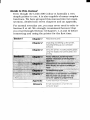


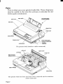
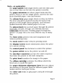

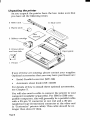


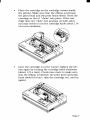
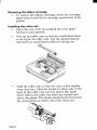
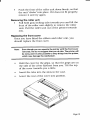


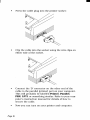
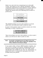
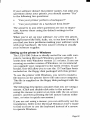


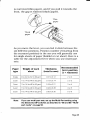
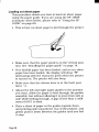

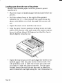

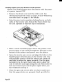
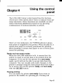
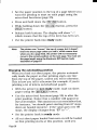

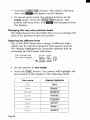


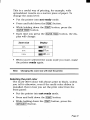
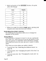


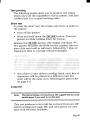
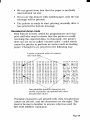
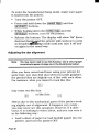
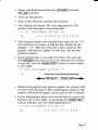
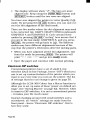


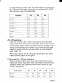
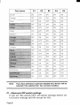

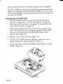
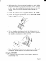
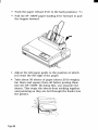
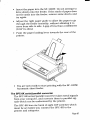
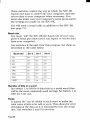
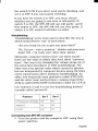
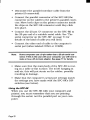


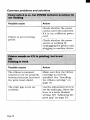


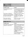
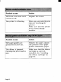
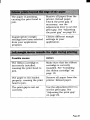
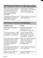
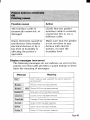
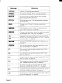

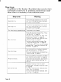
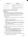
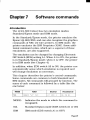

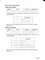
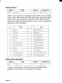
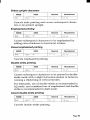
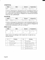

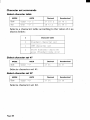
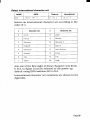

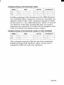
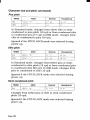

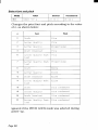
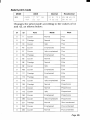
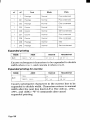
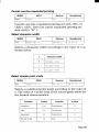
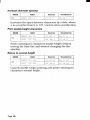
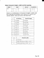
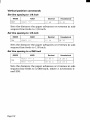
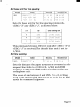

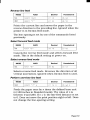
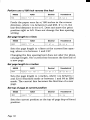


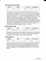
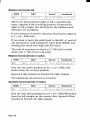
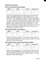
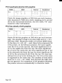
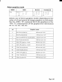
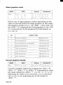

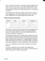
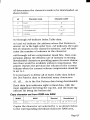
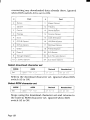
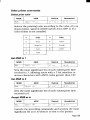
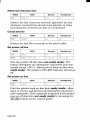
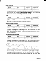

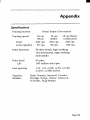
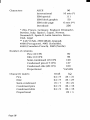

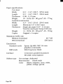
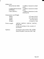
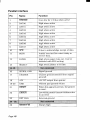

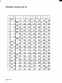
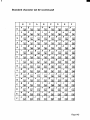
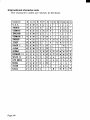


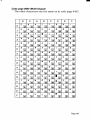
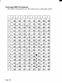
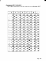
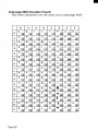
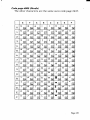
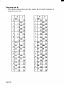

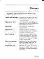
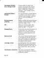

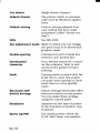


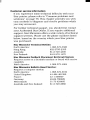
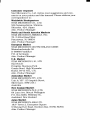


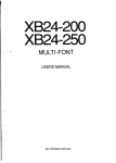

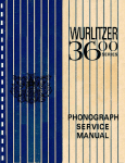


![Terms of Reference [ 462 KB]](http://vs1.manualzilla.com/store/data/005818895_1-55ed04ecdfa99aee80736235a8d4f256-150x150.png)