1
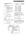
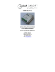
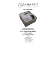
Gardasoft Vision Ltd
Units 1 and 2, Castle Acres, Elsworth
Cambridge, CB23 4JQ, UK.
Tel: +44 1954 200343
Fax: +44 1954 204343
Web: www.gardasoft.com
LC200 LED Lighting Controller
User Manual
Revision 03
3
Getting Started
Read the section on Safety.
Check “Lighting Types” to ensure that you have the correct
model of LC200 for your light.
Connect your light as described in “Connections.” Connect a
24V DC power supply and switch it on.
When the LC200 powers up it should automatically sense the
lighting unit. The light will flash for a while and then go to
50% intensity.
Output
Brightness
Allowed Pulse Width
Allowed Duty Cycle
0 to 100%
99ms
100%
Read the “Operation” section and use the buttons to vary the
brightness of your lighting unit.
101% to 200%
30ms
30%
201% to 300%
10ms
20%
Mount the LC200 as described in “Mechanical Fixing” using
a DIN rail.
301% to 400%
1ms
10%
401% to 500%
0.5ms
5%
Set up the LC200 for the continuous or pulsed operation and
test as described in the “Operation” section.
If an error occurs at any time refer to the “Error Code”
section.
Visit www.gardasoft.com for Application Notes on the
LC200.
4
Disclaimer
Except as prohibited by law:
All hardware, software and documentation is provided
on an “as is” basis.
It is essential that the user ensures that the operation of
the product is suitable for their application.
The user must ensure that incorrect functioning of this
equipment cannot cause any dangerous situation or
significant financial loss to occur.
Gardasoft Vision Ltd and Gardasoft Products Ltd will
not accept any liability for consequential loss of any
kind.
The LC200 is set up using three push buttons and a two digit
seven-segment display. Configurations are saved in nonvolatile memory so that the LC200 will resume operation
after a power cycle.
4.1
2.1.1
Safety - English
LC200 – Safety
Please read this before using the LC200. If in doubt, contact
your distributor or Gardasoft Vision.
Where this symbol appears in the manual, refer to
the text for precautions to be taken.
2.1.2
Electrical
The user must ensure that the potential difference between
any combination of applied signals does not exceed the
supply voltage. WARNING: Higher voltages may cause a
danger to personal health.
The LC200 does not have complete tracking isolation of
inputs and outputs.
Transients caused by inductive loads must be suppressed
external to the LC200.
2.1.3
General
The LC200 must not be used in an application where its
failure could cause a danger to personal health or damage to
other equipment.
If the equipment is used in a manner not specified by the
manufacturer, the protection provided by the equipment may
be impaired.
Specifications
Parameter
Value
Supply Voltage
Supply Current
30mA
This figure excludes the
current needed to drive
the output. The current
requirements may be up
to 2A at maximum
output.
Maximum Load
Voltage
32V DC
This can be higher than
the Supply Voltage.
Output Current
Up to 1.2A
continuous or 2A
pulsed
Input Logic High
5V to 24V
The LC200 comes in four versions:
Input Logic Low
<1 V
Ambient
Temperature
During Operation
5oc to 40oc
LC200-12V
For 12V lighting
LC200-24V
For 24V lighting
LC200-350
For 350mA lighting
LC200-700
For 700mA lighting
LEDs should be driven using a constant current source, not a
constant voltage. This is because small variations in
temperature or voltage can cause a large change in brightness
in LEDs. The brightness is approximately linear with current,
so by driving the lighting with a current, intensity control is
linear. Intensity control with voltage is very difficult because
of the extreme non-linearity of brightness with voltage.
Traditionally, many manufacturers have rated their lighting by
voltage, without giving a specification for the current
required. The 12V and 24V types above are designed to
support these legacy lights. When a 12V or 24V light is
connected, the LC200 automatically senses the current rating
of the lighting. It then drives the lighting using a constant
current, allowing all the advantages of current drive for
voltage rated lighting.
4.3
Output
Maximum
Relative
Humidity During
Operation
6
Continuous:
In continuous mode the output is a continuous current.
Pulsed:
In this mode output is pulsed once per trigger. A digital
input is used as a trigger. The delay and pulse duration
can range from 100 microseconds to 1 milliseconds in
100 microsecond steps and from 1 millisecond to 99
milliseconds in 1 millisecond steps.
In continuous mode, the output current can be varied from 0%
to 100% of full brightness.
This is the voltage
applied between the +ve
and –ve of the trigger
input
90%rH noncondensing
Maximum Unit
Power
Dissipation
3W
Mechanical Fixing
The LC200 can be fixed onto a standard 35mm DIN rail.
The LC200 does not have an IP rating and should be mounted
so that moisture and dirt cannot enter the unit.
An enclosure may also be required for other parts of the
system such as power supplies and will provide mechanical
and environmental protection in industrial applications.
7
Two modes of operation are provided:
Notes
24V DC ±5%
regulated
Lighting Types
All trademarks acknowledged. Hardware, software and
documentation are Copyright 2002 – 2005 Gardasoft Products
Ltd. Hardware manufactured by Gardasoft Vision Ltd under
licence.
2
5
Safe-Sense™ Technology
The LC200 provides automatic, fool-proof operation for
voltage rated lighting. Select the LC200-12V or LC200-24V
as appropriate for your light. The LC200 will detect the
connection and disconnection of the light and on connection
will automatically sense the current rating of the light.
4.2
So for example, if the brightness is set to 350%, then the
LC200 will not allow pulses greater than 1millisecond long. If
the trigger pulses are too close together so that the lights are
on for more than 10% of the time, the LC200 will stop the
output and flag an error.
General Description
The LC200 current controller provides repeatable control of
LED lighting for machine vision applications including power
supply, intensity control, timing and triggering functions.
1
In pulsed mode, the brightness can be set up to 500% of its
rating, but only for short periods and at low duty cycles, so
that the lighting does not overheat and get damaged. This is
also limited by the maximum allowable pulse current of 2A
(e.g. if a lamp takes 1A continuously, then the maximum
output brightness would be 200% regardless of pulse width
and duty cycle)
7.1
Connections
General
All connections are made via screw terminations on the side
of the unit.
Ensure that the wire gauge used for these connections is
appropriate for the current to be drawn. Ideally, wires should
be secured to ensure they cannot come loose. Route low
voltage and mains wiring separately. If they must be loomed
together ensure that low voltage insulation rating is sufficient
or that supplementary insulation is used.
Gardasoft Vision Ltd
Units 1 and 2, Castle Acres, Elsworth
Cambridge, CB23 4JQ, UK.
Tel: +44 1954 200343
Fax: +44 1954 204343
Web: www.gardasoft.com
7.1.1
Power Connections
The LC200 should be powered from a single +24V DC
supply.
The power is connected on the V+ and GD (ground) screw
terminals.
7.1.2
Signal Connections
See the Specifications Section for the electrical limits on these
connections. Check all connections carefully before switching
on.
Ensure that the polarity of V+ and
GD is correct.
The digital trigger input is marked T+ and T-, and should be
connected to a suitable +5 to +24V trigger source, or left
unconnected when not used.
8.3
Current Sensing
When no light is connected, the LC200 displays “nc” and
continually checks for a light being connected. When it
detects a light, it will display “SN”.
For the LC200-350 and LC200-700 the controller knows what
the current rating of the light is so no further sensing is
required.
For the LC200-12V and LC200-24V, the controller will
automatically sense the current rating of the light by
increasing the output current until the voltage rating is
reached.
Once the LC200 has detected the light and is ready to operate,
two alternating bars are shown on the display. By default the
output is set to continuous at 50% of full brightness.
millisecond and the time is adjustable in 0.1 millisecond
steps. From 1 millisecond upwards, the display will show “1.”
to “99.” and the time will be adjustable in 1 millisecond steps.
Note, if at any time a mistake is made, it will be necessary to
go through the menu again.
Triggers occur on the leading edge of the trigger input, that is
on the transition from 0V to (for example) 5V input.
When setting up lighting, the user can press the DOWN
button on the LC200 to simulate a trigger and generate an
output pulse.
When a trigger is received, the display shows “PL” briefly to
show that the light is being pulsed.
9
The following error messages are displayed on the LC200
display.
Connect the LED lighting to L+ and L-.
8.4
Error
Reason
E1
While sensing the current rating, the
output became open circuit
E2
While sensing the current rating, the
required voltage could not be reached
E3
While sensing the current rating, the
output current was incorrect
EC
Over driving protection in pulse mode.
The pulse trigger rate is too high.
ET
Thermal cutout. Internal temperature is
too high.
SH
Output connection is short circuit
OP
Output connection is open circuit
PO
Internal power protection cut out
Connected State
Once the LC200 has detected that a light is connected and the
current rating has been determined, the user can then set up
the LC200 for Continuous or Pulsed output.
8
Error Codes
Operation
The LC200 is set up using the push buttons and display on the
front of the unit. The set up is non-volatile, so the LC200 will
resume the same operation after a power cycle if a light is
connected.
Gardasoft LED Lighting
Controllers
The overall operation is given below.
The following products are available at the time of writing.
New products will be introduced. See www.gardasoft.com for
details of the current range.
8.4.1
Continuous Output
To set up continuous mode:
Press and hold the SEL button for one second
Select “SC” using the up and down buttons
Press SEL
Set the brightness from 0 to 99 (percent)
Press SEL.
As the brightness setting is changed the brightness of the light
will also change.
8.4.2
Pulsed Output
When pulsing the lighting, three parameters are available:
8.1
Power Up
Brightness
Delay from trigger to pulse
Length of pulse
On power up, the LC200 will display “8.8.” to test the display
is working, then “LC”, “20”, followed by the version number,
eg “01”, and then will be ready for operation. To show that
the unit is operating normally, an alternating pattern is drawn
on the display.
The brightness can be adjusted from 0.1 (10%) to 5.0 (500%)
of the continuous brightness. There are limitations between
the set brightness level, and the maximum allowed pulse
length/duty cycle, refer to the General Description for details.
The unit will initially show “nc” on the display until a light is
connected.
To set up pulse mode:
8.2
Cold Start
In the unlikely event that the non-volatile memory becomes
corrupt the LC200 may not start up properly. In this case the
memory can be cleared by powering up the LC200 while
holding down the SELECT and DOWN buttons. The LC200
will display “CL” for about 5 seconds while the memory is
cleared.
Press and hold the SEL button for one second
Select “SP” using the up and down buttons
Press SEL
Set the brightness from 0.0 to 5.0
Press SEL
Set the pulse delay from 0.1 to 99 milliseconds
Press SEL
Set the pulse width from 0.1 to 99 milliseconds
Press SEL
When the user is setting up the pulse delay and pulse width,
the display will show “0.1” to “0.9” for periods less than 1
LC200 Range
•
•
•
•
1 output channel up to 2A
Models for voltage and current rated lights
1 digital input
SafeSenseTM Technology
PP600 Range
•
•
2 output channels up to 10A each
2 digital inputs
PP600
PP610
Lighting controller
Lighting controller with RS232
PP701
DIN Rail mounting clip for PP600 and PP600F
range
PP600F Range
•
•
•
Same as the PP600 range but with fast pulsing
Pulse delay from 10us to 9.9ms in 1us steps
Pulse width from 1us to 9.9ms in 1us steps
PP600F
PP610F
Lighting controller
Lighting controller with RS232
PP860, PP861
•
•
•
•
High current, high accuracy controller
8 output channels up to 20A each
Pulses accurate to 0.1 microseconds
RS232 configuration