1
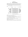
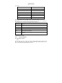
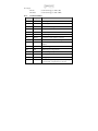
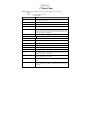
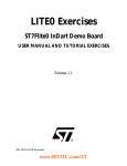
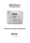
USER MANUAL
PP420, PP420F
LED Lighting Controllers
Revision 06
Gardasoft Vision Ltd
Trinity Court, Swavesey
Cambridge, CB24 4UQ. UK
Tel: +44 1954 234970
Fax: +44 1954 231567
Web: www.gardasoft.com
1
Disclaimer
Except as prohibited by law:
All hardware, software and documentation is provided on an “as is” basis.
It is essential that the user ensures that the operation of the product is suitable for their
application.
The user must ensure that incorrect functioning of this equipment cannot cause any
dangerous situation or significant financial loss to occur.
Gardasoft Vision Ltd and Gardasoft Products Ltd will not accept any liability for
consequential loss of any kind.
All trademarks acknowledged. Hardware, software and documentation are Copyright 2002 –
2010 Gardasoft Products Ltd. Hardware manufactured by Gardasoft Vision Ltd under licence.
2
Getting Started
Read the sections on Safety and Specifications and check the PP420 fulfils your requirements.
See the back cover for other Gardasoft Vision lighting controllers. Connect the PP420 up to a
power supply, Ethernet network and lights as described in Connections.
Mount the PP420 as described in “Mechanical Fixing” using a DIN rail or the mounting holes.
Read the section on Heat Dissipation. Set up the PP420 for the desired operation and test.
Download, install and run the PP420 Configuration Program from www.gardasoft.com. If you
need to use a fixed IP address set this up using the Configuration Program.
Search for the PP420 on the network and then connect to it.
On the Configuration tab, set up the current rating of the lighting and the mode of operation of
each light.
Visit www.gardasoft.com for Application Notes. There is also a Support page which has
information on troubleshooting problems.
Throughout this manual, references to the PP420 refer to all variants in the PP420 range unless
otherwise stated. The symbol “us” is used to denote microseconds.
3
3.1.1
Safety - English
PP420 – Safety
Please read this before using the PP420 family of products. If in doubt, contact your distributor
or Gardasoft Vision.
Where this symbol appears in the manual, refer to the text for precautions to be taken.
3.1.2
Heat
The PP420 can get very hot. It should be positioned where personnel cannot
accidentally touch it and away from flammable materials.
Read the section on Heat Dissipation. Do not exceed the power ratings given in the manual. Note
that at the maximum ratings the case temperature can reach 80oC.
3.1.3
Electrical
The user must ensure that the potential difference between any combination of applied signals
does not exceed the supply voltage. WARNING: Higher voltages may cause a danger to personal
health.
The PP420 does not have complete tracking isolation of inputs and outputs.
Transients caused by inductive loads must be suppressed external to the PP420.
3.1.4
General
The PP420 must not be used in an application where its failure could cause a danger to personal
health or damage to other equipment.
If the equipment is used in a manner not specified by the manufacturer, the protection provided
by the equipment may be impaired.
4
General Description
The PP420 current controller provides repeatable intensity control of LED lighting for machine
vision applications. It includes the power supply, intensity control, timing and triggering
functions required for machine vision systems.
LED lighting needs a constant current supply as small variations in voltage can cause large
variations in light output. Currents can be specified in 2.5mA steps to give very fine control of
intensity.
Three modes of operation are provided separately for each channel:
Continuous
In continuous mode the output is a continuous current.
Pulse (Strobe)
In this mode output is pulsed once per trigger. One trigger input is used as a trigger. The
delay and pulse duration can range from 20us to 1 second in 20us.
Switched
In switched mode a trigger input can be used to switch the output current on and off. The
output is only enabled when the input has a voltage on it.
Configurations are saved in non-volatile memory so that the PP420 will resume operation after a
power cycle.
The PP420 is set up using the push buttons and display on the front of the unit or using Ethernet
commands. The set up is non-volatile, so the PP420 will resume the same operation after a power
cycle.
4.1
Default Configuration
When shipped the PP420 has the following configuration:
Ethernet set to DHCP mode
Each channel set to 0.1A rating, no autosense, continuous output at 50%
4.2
Automatic Light Sensing
When a channel does not have a light connected, the PP420 continually tries to put out a very
small current. Each channel operates independently.
When a light is connected, it will flash for a short time (the light will not be damaged by this)
until the PP420 detects that it is connected.
If the AUTO_SENSE flag is set or a current rating has not been entered for this channel then the
PP420 will wait for the current rating to be set. This flag can be set using the Configuration
Program, Channel Configuration webpage or using the RR command from an application
program.
If Ethernet messages are enabled, when a light is connected and the user is being prompted to
enter the current rating, the PP420 will send one of these two messages:
Evt c,129
A light has been detected and the current rating needs to be
input
Evt c,128
A light has been detected and the current rating is not needed
Where “c” is the output channel number. An application can send an RR command back in reply,
which will cancel the user prompt.
Once the PP420 has detected the light and has a current rating for it, the light will start its
configured operating mode.
The RE Ethernet command can be used to enable/disable the current rating request. The PP420
will then use the previously entered current rating.
If the PP420 is turned off and on again, without an error occurring, then the PP420 will autosense the light and assume it is the same light and so will not prompt for the current rating again.
Once an error has occurred, the user will be prompted next time a light is detected.
When a light has not been detected the following reasons can be displayed on the webpage:
Error
Reason
Reset
No connect – (reason)
Light not detected
Detecting
Light is currently being detected.
Waiting for current rating
The current rating needs to be entered. The light has been
detected, but the AUTO_SENSE flag is set and the controller is
waiting for the current rating to be entered.
Connected
Light operating normally
Error – nn
The light was operating but has been turned off due to an error
(see appendix C)
The user must press SEL to cancel the error (or send command “GR” using the Ethernet
connection) and the PP420 will then re-sense the light and ask for confirmation of the current
rating.
4.3
Output Modes
There are four trigger inputs. The sense of these signals can be active high or active low, as set
by the “P” flag.
The trigger inputs are used as follows:
Mode
Trigger Input
Output
Continuous
Don’t care
Output is on.
Switched
Trigger = 0V
Output is off
Trigger = 4.5V to 24V
Output is on
Trigger goes from 0V to 4.5V
Pulse is
triggered
Trigger goes from 4.5V to 0V
No action
Pulsed
4.3.1
Continuous Output and Switched Output
In continuous mode the output current is fixed and continuous. Switched mode uses a trigger
input to switch the output on or off.
In continuous and switched modes, the output current can be varied from 0% to 100% of full
brightness.
4.3.2
Pulsed Output
The output is off by default. When a trigger is the PP420 will wait for a delay and then pulse the
output. The delay, pulse width and pulse intensity are all configurable.
If the “P” flag is set triggers occur on the leading edge of the input, that is on the transition from
0V to (for example) 5V.
In pulsed mode, the brightness can be set up to 999% of its rating, but only for short periods and
at low duty cycles, so that the lighting does not overheat and get damaged. The default limits are
as follows. Other limits are available.
Output Brightness
Allowed Pulse
Width
PP420, PP420
Allowed Pulse
Width
PP420F, PP420F
Allowed Duty Cycle
0 to 100%
999ms
10ms
100%
101% to 200%
30ms
1ms
30%
201% to 300%
10ms
1ms
20%
301% to 500%
2ms
1ms
10%
501% to 999%
1ms
0.5ms
5%
So for example, if the brightness is set to 350%, then the PP420 will not allow pulses greater than
2ms long. If the trigger pulses are too close together so that the lights are on for more than 10%
of the time, the PP420 will stop the output and flag an error.
4.3.3
Current Protection
The PP420 monitors the output current and voltage and ensures it is within acceptable limits. The
RE Ethernet command can be used to disable error checking.
This is not absolute protection but does provide some safety when setting up the PP420.
4.3.4
Channel Flags
Each channel has some configuration flags.
S Flag enables or disables autosensing. When this flag is set, the PP420 will autosense - when a
light is connected for the first time, the PP420 will wait for the current rating to be entered (using
the webpage, Config program or UDP message) before continuing. When this flag is not set, the
PP420 will use the previously set current rating.
E flag enables or disables error checking. When this flag is not set, the PP420 will not detect
lighting errors.
P flag inverts the trigger signal. In pulse mode, when set the PP420 triggers from the rising edge
of the trigger. When not set, the PP420 triggers from the falling edge. The falling edge may give
a slower response time. In Switch mode, when the flag is set, the output is on when the input is
on. Clearing the P flag inverts this operation.
5
Parameter
Specifications
Value
Notes
Digital supply
voltage (PSU+)
12V DC to
48V DC
regulated
Must be at least 1V greater than
the load potential difference at
maximum required current
Supply current
with no lights
connected
120mA
This is with a 12V supply. The
current is lower at 24V.
Input enable level
From 3V to
24V
Input disable
level
<1 V
Typical trigger
input current
required
3mA at 3V to
24V
Maximum output
current per
channel
2A continuous
or 10A pulsed
Ambient
temperature
during operation
5oc to 50oc
The ambient temperature may
need to be lower if the PP420 is
dissipating a lot of heat
Total allowed
power dissipation
without
heatsinking (PD)
PD=8 Watts
(max)
See Section 7 for information on
heat dissipation
This is the voltage applied
between the positive and
negative of each trigger input
6
Mechanical Fixing
The PP420 can be mounted onto a flat surface using the mounting holes in the corners, see
diagram. The PP420 should only be mounted either vertically or with its base horizontal. It
should be mounted at least 15mm away from the sides of plastic enclosures. Likewise leave a
similar space between the PP420 and any parts which could be affected by high temperatures.
The enclosure of the PP420 is used to dissipate power in the form of heat. See the
section on Heat Dissipation.
The PP420 can be mounted from above using the corner holes, or from beneath using the M4
tapped holes (maximum screw length inside is 6mm).
The PP701 kit is available for mounting the PP420 on a DIN rail.
To avoid a fire hazard consider the implications of overheating in the unlikely event of a
fault in the PP420. The power dissipation in a fault condition is approximately given by
the sum of the following for the four channels:
(<Power supply voltage> - <rated voltage for lighting>) * <max current delivered by Power supply>
Either limit the power supply output current(s) so that not more than 30W can be dissipated in
the PP420, or mount the unit in an enclosure.
To limit the power, set the power supply output voltages to the minimum value required by the
LED light and the PP420 together. Chose a PSU that limits its output current by design, by
setting the current limit on the supply (if this feature exists) or use fuses. Remember to derate the
fuse, if mounted in an enclosure, as the temperature will be higher than ambient.
The PP420 enclosure is a fire enclosure as long as the following conditions are met:
•
The Ethernet connector must not be facing downwards
•
The mounting holes on the underside must be covered or have a screw fitted.
If an enclosure is used, the enclosure should be metal or plastic (with a flammability rating of
UL94 V1 or better); with no holes below or to the sides of the PP420 when mounted. Cable
entries below the PP420 should be via glands that have a flammability rating as before. Observe
the specified gap between the PP420 and any other part or side of the enclosure.
The PP420 does not have an IP rating and should be mounted so that moisture and dirt cannot
enter the unit.
7
Heat Dissipation
The PP420 has a linear circuit to produce the constant current output. This means that it
generates heat which needs to be dissipated.
See application note APP926 for more information on heat dissipation and a spreadsheet There is
a spreadsheet available (APP939) which gives an easy way to work out the heat dissipation of the
PP420.
7.1.1
Heat Output Per Channel
For a continuous output current the heat output is given by:
<heat output (W)> = <output current (A)> * ( <supply voltage (V)> - <voltage across lighting (V)> )
where:
Output current
Set by the user
Supply voltage
Voltage across PSU+ and PSU-
Voltage across lighting Voltage across LD1+ and LD1- (for channel 1)
This is usually easy to calculate as the voltage across the lighting is usually the voltage rating of
the light given in its specification or can be measured using a voltmeter.
For a pulsed output the heat output is given by:
<heat output (W)> = <output current (A)> * <duty cycle>
* ( <supply voltage (V)> - <voltage across lighting when pulsing (V)> )
<duty cycle> = <pulse width in seconds> * <trigger frequency in Hertz>
When overdriving, the voltage across the lighting is more difficult to find out. In most cases it is
reasonable to use the voltage rating of the light.
7.1.2
Total Heat Output
The heat output for the PP420 is given by adding the heat output for both channels, as calculated
above.
There are several ways to reduce the heat output from the PP420:
•
Use pulse mode. If the output is only on when you need it then you can dramatically reduce
the heat output. Feed the camera trigger into the PP420 and pulse the lights.
•
Turn the light off when not needed. If you don't have precise timing of when the camera
will trigger, you can use Switched mode to switch the output off or on depending on the
trigger input (or use the PP420 and use Ethernet commands to turn the output on and off).
•
Reduce the output current if possible
•
Reduce the supply voltage. Most PSUs have some adjustment in their output voltage.
•
Connect lights in series instead of parallel. If you have an array of lights or LEDs in
parallel then changing the arrangement to serial will increase the voltage across them but
reduce the overall current.
•
Use two PP420s and use one channel from each. For high power applications this may be
the easiest solution. Even with one light, it is possible to parallel up two output channels
from different PP420s.
•
Use a PP820. These controllers can dissipate much more heat.
With no heatsinking and no airflow, the PP420 can dissipate approximately the following:
8W at 30OC ambient
6W at 40OC ambient
4W at 50OC ambient
If the heat output is no greater than these limits, then no heatsinking is required. If the heat output
is above but less than 24W then the PP420 needs to be bolted to a solid piece of metal to
dissipate the heat. Above 24W, it is necessary to have a large heatsink with fan cooling.
LED1LED1+
POWER/LOAD
LED2+
LED2-
PSU-
Power Supply –
ve (GND)
LED4+
LED4TRIG A
- see
illustration
to right
Operating Conditions
Channel 2
output to lighting
Power Supply
+ve
LED3+
TRIG1-
Channel 3
output to lighting
Channel 4
output to lighting
Trigger input 1
TRIG1+
TRIG2TRIG2+
TRIG3-
Trigger input 2
Trigger input 3
TRIG3+
TRIG4TRIG4+
Opto-Coupled Trigger Input Details
Channel 1
output to lighting
PSU+
LED3-
TRIG B
- see
illustration to
right
Connections
Function
Screw
Terminal
ID
Connector
8
Trigger input 4
3V ∗ VTRIG ∗ 24V
Logic 1
VTRIG ∗ 1V
Logic 0
VF
1.5V typ
Ensure that the wire gauge used for these
connections is appropriate for the current to
be drawn. Ideally, wires should be double
crimped or independently secured to ensure
they cannot come loose. Route low voltage
and mains wiring separately. If they must be
loomed together ensure that low voltage
insulation rating is sufficient or that
supplementary insulation is used.
The PP420 has a single power input
connection (which is different from the
PP600).
Power supplies should be regulated with
SELV compliant outputs (fault tolerant).
Consideration should be given to fusing
PSU+. The fuse value can be based on the
average current output. Note that in Europe
fuses are designed to conduct at their rated
current, while in the USA fuses are designed
to blow at their rated current.
The RJ45 Ethernet connector requires a
straight through cable to connect into a
network switch, hub or router. It runs at
10Mbits per second.
9
Ethernet Setup
You may need to ask your network administrator for advice about setting up the Ethernet
connection.
Ethernet set up is not affected by cold booting the PP420.
9.1
Connection
The Ethernet link uses a 10 base-T connection on an RJ45 connector. The PP420 will usually be
connected to a network switch (or hub or router). It is also possible to connect it direct into the
network port on a PC by using a swapover cable.
9.2
MAC Address
The PP420 MAC address is:
0x00.0x0B.0x75.0x01.0xNN.0xNN.
9.3
IP Address
The PP420 needs an IP address to communicate over Ethernet. There are two ways to get an IP
address; either programmed into the unit or using DHCP.
Most networks use a DHCP server. If there is a PC on the network, You may be able to find out
whether a PC on the same network uses DCHP as follows:
•
Go to Control Panel
•
Select Network Connections
•
Right click on Local Area Connection. Select Properties
•
From the list, select Internet Protocol (TCP/IP), press Properties
If “Obtain an IP address automatically” is set, then DHCP is probably used. However, there may
be an alternative fixed IP address on the “Alternative Configuration” tab.
You can find out what IP address is being used by a PC at any time by:
•
Go to Control Panel
•
Select Network Connections
•
Right click on Local Area Connection. Select Status
•
Select the Support tab. The IP address is displayed
When using a fixed IP address, you must ensure that you use an IP address that is not being used
by any other device on the network. It is usual to keep the first three numbers of the IP address
the same as other devices and to change only the last number. For example, if you have a
network consisting of a PC (IP address 192.168.1.35) and two PP420s, you might give them
addresses 192.168.1.201 and 192.168.1.202.
9.3.1
Programmed IP Address and DHCP
For DHCP mode, the PP420 acquires its IP address, subnet mask and gateway address from a
DHCP server. Otherwise the PP420 has a fixed IP address, subnet mask and gateway address.
DHCP mode or a fixed IP Address can be set up using the PP420 Configuration Program. This
will work on any network, as the Configuration Program broadcasts the network setup message
to the PP420. The message includes the serial number to ensure that other Gardasoft products
ignore the message.
The default configuration is DHCP mode. The IP address can also be detected using the
Configuration Program.
The Configuration Program is available for download at www.gardasoft.com.
10
Communication
All the features below are implemented in a Configuration Program available from
www.gardasoft.com.
10.1.1
Automatic Sensing
The PP420 will send out a message on three events:
•
On power up
•
When an IP address is received or renewed by DHCP
•
When an enquiry message is received
On the first two events, the message is broadcast. On the third it is a reply to a single IP address.
An enquiry message is a UDP packet from source port 30310, destination port 30311 with the
message body “Gardasoft Search” (8-bit ASCII, 13 characters).
The message output by the PP420 is a UDP packet from source port 30311, destination port
30310. It is formatted as:
Gardasoft,PP420,000000,111111111111,22222222
(8-bit ASCII, 44 characters), where
000000
the serial number of the unit
111111111111
the MAC address in 6 HEX bytes
22222222
the IP address in 4 HEX bytes
For example for PP420 serial number 12345, IP address 192.168.1.103, MAC address
00.0B.75.01.80.99 the packet will contain
Gardasoft,PP420,012345,000B75018099,C0A80167
11
Webpage Configuration
The PP420 has a small webserver inside, so that it can be configured from a standard web
browser, such as Internet Explorer.
The IP address of the PP420 must be known (see the section on “Ethernet Setup.” Open a web
browser window and type the IP address (for example 192.168.1.71) of the PP420 into the URL
box at the top. The main page of the PP420 webserver should be shown.
The configuration pages can be protected using a password.
11.1
Index Page
The index page shows general information about the PP420. Links are provided to the configuration pages.
11.2
General Configuration Page
The General Configuration page allows the webpage protection password to be set or cleared and
the internal trigger to be set up. Also any Ethernet command from Section 12 can be entered.
“Test Mode” referred to on this page is the internal trigger timer.
11.3
Channel Configuration Pages
There is one Channel Configuration Page for each output channel. All the parameters for each
output channel can be set up. Press the Submit button to update the PP420 and save the changes
to non-volatile memory.
12
12.1
Ethernet Configuration
Communication
The PP420 can be configured via the Ethernet connection using UDP or TCP/IP. A
Configuration Program with source code can be downloaded from www.gardasoft.com.
Communication consists of commands sent by the host (controlling PC). All output generated by
the command is returned in reply UDP or TCP/IP packets. The last character sent is “>” (“greater
than” symbol). Once this is received, the host knows that the command has been completed.
It is recommended that the host waits for the “>” symbol before sending the next command. UDP
communications are not guaranteed to arrive, so the host software must be able to cope with lost
messages.
Using the GT command, a host can request that a message is sent to it whenever an error occurs.
For TCP and UDP, commands from a host should be sent to destination port 30313. Replies will
be to destination port 30312.
A TCP/IP connection will timeout and close if it is idle for more than 10 seconds. The host must
send regular “heartbeat” commands (eg “VR”) to keep the link open.
12.2
Configuration Program
A Configuration Program is available from www.gardasoft.com which allows the PP420 to be
configured using the commands below.
12.3
Command Structure
Several commands can be put into one command line by separating them by a semi-colon (“;”).
A carriage return character should be sent to terminate the command line. The PP420 will send
any replies to the commands and then send a ‘>’ character to indicate that the command line has
been completed.
Commands comprise a code of two letters followed by the parameters (if any) needed for the
command. Spaces in the commands are ignored.
Numeric parameters are separated by a comma (“,”). For a parameter which is a time period the
default units are milliseconds. “s”, “ms” or “us” can be added to the end of the number to
indicate seconds, milliseconds or microseconds. For currents, “a” or “ma” can be added to
indicate “amps” or milliamps”. The default is amps.
For example:
Parameter
Meaning
0.1
0.1 milliseconds
200us
200 microseconds
0.1s
0.1 seconds
100ma
100mA
2.45A
2.45A
2.3
2300mA or 2.3A
Note that parameters are in “USA/UK” format so that a half is written “0.5” not “0,5”
The command codes and their meaning are described below. The upper case commands are
shown, followed by lower case letters denoting the numeric argument.
Error number
Reason
Err 1
A parameter value is invalid
Err 2
Command not recognised
Err 3
Numeric value is wrong format
Err 4
Wrong number of parameters
Err 5
(Warning only) A timing parameter was out of range and has been
adjusted.
Any changes made using Ethernet commands are not saved permanently until the AW
command has been issued.
12.3.1
General Commands
Save the settings to memory.
AW
Once the settings are saved to memory they are then retained when the unit is switched off. If
this is not done, changes to the settings are volatile, and if the unit is switched off they revert to
those in force when the last AW command was issued.
Report the configuration
ST
Typical output is:
CH 1, MD 2, IP 4, CS 0.100A, SE 75.0, DL 2.0us, PU 300.0us, RT 500.0us, FL 1
CH 2, MD 0, IP 2, CS 0.100A, SE 25.8, DL 1.000ms, PU 1.000ms, RT 0.0us, FL 0
CH 3, MD 0, IP 1, CS 0.100A, SE 50.0, DL 1.000ms, PU 1.000ms, RT 6.000ms, FL 4
CH 4, MD 1, IP 4, CS 0.100A, SE 100.0, DL 100.0us, PU 1.000ms, RT 0.0us, FL 5
Where the numeric values are:
CH
Channel number
MD
Mode: 0 = continuous, 1 = pulse, 2 = switched
IP
Trigger input: 1, 2, 3, 4
CS
Current rating of the light
SE
Brightness percentage setting
DL
Pulse delay
PU
Pulse width
RT
Retrigger delay
ST0
Reports the general settings. Typical output is:
TM 1, TP 20.00ms
STc
Where
c
channel number (1 or 2)
Reports settings for a single channel.
Enable Ethernet Messages
GTm
m
= 0 to disable Ethernet messages
= 1 to enable Ethernet messages
When Ethernet messages are enabled, any error reports are sent to the most recent UDP or TCP
address from which a command has been received.
Messages are of the form:
Evtc,e
Where
c
zero for no channel or channel number (1 or 2)
v
event value:
32 to 47 Lighting error code
128
Light detected and waiting for current rating
129
Light detected and not waiting for current rating
Clear any Errors
GR
If Ethernet messages are not enabled, the last event or error number can be read by this
command. Any error displayed on the unit is cleared, so if there was a lighting error, the PP420
will resume auto-sensing on that channel.
The reply will be in he same form as the GT command above. If ther are no outstanding events or
errors, then only the prompt “>” is returned.
Report the version of firmware running in the PP420
VR
This command returns the firmware version. For example:
PP420 (HW001) V002
Clear Settings
CL
Clears the output channel configuration. This excludes the Ethernet settings. For each channel, if
the AUTO_SENSE flag is set, then the flag and the current rating are preserved.
Set/Clear the Webpage Password
EY
EY asc1, asc2, asc3, asc4, asc5, asc6
This command sets the password required to access the webpages. If EY is entered on its own
then the password is cleared. There are six optional parameters, which are ASCII values for a
password from one to six letters. A value of 65 is ‘A’, 66 is ‘B’, etc to 90 is ‘Z’.
Set the Channel Flags
REc,m
Where:
c = output channel (1, 2, 3, 4)
m = Flags, where
bit 0
1 = No autosense (current rating is fixed)
0 = Autosense (current rating needs to be entered on connection)
bit 1
1 = No error detect
0 = Error detect. The PP420 continually monitors the output current and
voltage
bit 2
1 = Negative trigger. In pulse mode the trigger is the falling edge. In
switched mode a low input turns the light on.
0 = Positive trigger. In pulse mode the trigger is the leading edge. In
switched mode a high input turns the light on.
Set the trigger input
This command changes which input is used when in switched or pulsed modes.
RPc,t
Where:
c = output channel (1, 2, 3, 4)
t = trigger input (1, 2, 3, 4)
Set the output current rating
This command changes the current rating for a light.
RRc,v
Where:
c = output channel (1, 2, 3, 4)
v = rated current (10mA to 2A)
Set continuous mode
The output is set to continuous mode at a percentage of full brightness.
RSc,s
Where:
c = output channel (1, 2, 3, 4)
s = setting in percent (s = 0 to 100)
Set switched mode
The output is set to switched mode at a percentage of full brightness.
RWc,s
Where:
c = output channel (1, 2, 3, 4)
s = setting in percent (s = 0 to 100)
Set pulse mode
The output can be set up to pulse on a trigger input. The delay from trigger to the start of the
pulse, the length of the pulse and the brightness are configurable.
An error is generated if the brightness setting requires a current greater than 10A or if the
combination of pulse width and setting is not allowed.
RTc,p,d,s
RTc,p,d,s,r
Where:
c = output channel (1, 2, 3, 4)
p = pulse width in milliseconds (0.02 to 999)
d = delay from trigger to pulse in milliseconds (0.02 to 999)
s = setting in percent (s = 0 to 999)
r = retrigger delay. This parameter is optional
Simulate an Input Trigger
TRc
c which input channel (1, 2, 3, 4)
Simulates a trigger pulse. If the channel is in pulse mode it will pulse and show “PUL” on the
display.
Set Internal Trigger
Enable or disable the internal trigger. When enabled, all outputs are triggered simultaneously
using an internal trigger signal. This setting can be saved to non-volatile memory using the AW
command.
TT0
Disable internal trigger
TT1
Enable internal trigger (uses previously set period)
TT1,p
Enable internal trigger and set the period
Where:
p= period of the triggers in microseconds
For example:
TT1,200
TT1,500US
12.3.2
Set the internal trigger to 200ms (5Hz)
Set the internal trigger to 500us (2KHz)
Command Summary
Command
Example
Effect
AW
AW
Save changes
ST
ST
Show configuration
GT
GT1
Enable Ethernet messages
GR
GR
Get any error codes
VR
VR
Red the firmware version
RR
RR1,0.2
Set the rating of channel 1 to 0.2A
RS
RS2,65
Set channel 2 to 65% brightness continuous
RW
RW1,50
Set channel 1 to 50%, switched by Trig 1
RT
RT2,3,4,50
Set channel 2 to 3ms pulses, delayed by 4ms, at 50%
brightness
TT
TT1,1ms
Set internal triggers every 1ms
TR
TR2
Simulate trigger on trigger input 2
CL
CL
Clear all settings, except Ethernet
EY
EY80,87
Set webpage password to “PW”
RP
RP2,3
Use trigger input 3 for Channel 2
RE
RE1,3
Set channel 1 to ignore lighting errors and not prompt for
the current rating of a light when it is connected.
A. Timing
The following timings apply for firmware revision V014.
A.1 Switched Mode
The maximum delay from a trigger input changing to the output current being turned on or off is
10us.
A.2 Pulse Mode
For the PP420F the minimum pulse delay is about 4us.
B. Firmware Upgrade
On the PP420 and PP420F the firmware can be upgraded using the Ethernet interface. Contact
your distributor for more information.
C. Error Codes
If Ethernet message are enabled, these errors cause a message to be sent of the form:
Err c,e
Where:
c = output channel (1, 2, 3, 4)
e = error number
Error number
Reason
Err 1
A parameter value is invalid
Err 2
Command not recognised
Err 3
Numeric value is wrong format
Err 4
Wrong number of parameters
Err 5
One of the parameters is out of range. The value of the parameter has been
adjusted. For example, sending an RT command with a delay of 0 will get
a reply of “Err 5”. When the settings are viewed the delay will have been
set to 20us (PP420) or 4us (PP420F).
Err 8, 12
EEPROM corrupt. The configuration has been cleared.
Err 20
Couldn’t save settings to EEPROM.
Err 27
Can’t read Ethernet settings from EEPROM, so these may be incorrect.
Err 34
Internal power dissipation is too high. Output turned off
Err 35
Output current to lighting is too low.
Err 39
There is not enough supply voltage for the requested output current.
Err 36
The output is short circuit.
Err 42
The output current is too high.
Err 37
The voltage required for the lighting has increased too much. Check for
ageing of the lighting or a failed LED.
Err 38
The voltage required for the lighting has decreased too much. Check for
ageing of the lighting or a failed LED.
Err 44
Temperature error. The PP420 is too hot and has switched off to protect
itself.
Err 40, 41, 45
More current is being output than should be, so the PP420 has turned off
the outputs. This may be caused by a hardware error. Check with your
distributor.
Any other errors are internal errors.
Gardasoft LED Lighting Controllers
The products available at the time of writing include the following. Other products are also
available. See www.gardasoft.com for details of the current range.
RT Range
•
•
•
•
•
2, 4 or 8 output channels up to 20A each
2, 4 or 8 trigger inputs
SafePowerTM and SafeSenseTM
Front panel, RS232 or Ethernet configuration
Fast pulsing option
RT200-20
RT220-20
RT260-20
RT200F-20
RT220F-20
RT260F-20
RT420-20
RT420F-20
RT820F-20
RT860F-20
PP704
Lighting controller: 2 channels up to 20A pulsing, front panel
Lighting controller: 2 channels up to 20A pulsing, Ethernet
Lighting controller: 2 channels up to 20A pulsing, RS232
Lighting controller: 2 channels up to 20A fast pulsing, front panel
Lighting controller: 2 channels up to 20A fast pulsing, Ethernet
Lighting controller: 2 channels up to 20A fast pulsing, RS232
Lighting controller: 4 channels up to 20A pulsing, Ethernet
Lighting controller: 4 channels up to 20A fast pulsing, Ethernet
Lighting controller: 8 channels up to 20A fast pulsing, Ethernet
Lighting controller: 8 channels up to 20A fast pulsing, RS232
DIN Rail mounting clip for RT range
PP Range
•
•
•
•
•
2, 4 or 8 output channels up to 20A each
2, 4 or 8 trigger inputs
SafeSenseTM option
Front panel, RS232 or Ethernet configuration
Fast pulsing option
The PP range will continue to be available for many years.
Machine Vision Timing Controller
CC320 Controller
•
•
•
•
•
•
8 digital inputs
8 digital outputs
1 or 2 wire Encoder input
Very flexible operation
Ethernet control
Front panel configuration
PP703
DIN Rail mounting clip for CC320