
1
MultiUAV2 Simulation
User’s Manual
Version 2.0
Copyright © by SIAM.
Unauthorized reproduction of this article is prohibited.
Copyright © by SIAM.
Unauthorized reproduction of this article is prohibited.
Contents
List of Figures
vii
List of Tables
ix
1
Background
1.1
Overview . . . . . . . . . . . . . . . . . . . . . . . . . . . . . . . . .
1.2
Implementation . . . . . . . . . . . . . . . . . . . . . . . . . . . . .
1.3
Using This Manual . . . . . . . . . . . . . . . . . . . . . . . . . . .
1
1
2
3
2
Getting Started
2.1
Setting Up the Simulation . .
2.2
Running the Simulation . . .
2.3
The Graphical User Interface
2.4
Simulation Output . . . . . .
2.5
Simulation Data Plot Window
7
7
7
8
9
9
3
.
.
.
.
.
.
.
.
.
.
.
.
.
.
.
.
.
.
.
.
.
.
.
.
.
.
.
.
.
.
.
.
.
.
.
.
.
.
.
.
.
.
.
.
.
.
.
.
.
.
.
.
.
.
.
.
.
.
.
.
.
.
.
.
.
.
.
.
.
.
.
.
.
.
.
.
.
.
.
.
.
.
.
.
.
.
.
.
.
.
.
.
.
.
.
.
.
.
.
.
.
.
.
.
.
.
.
.
.
.
Embedded Flight Software (Managers)
13
3.1
Overview . . . . . . . . . . . . . . . . . . . . . . . . . . . . . . . . . 13
3.1.1
Redundant Central Optimization . . . . . . . . . . . . . 13
3.1.2
Sequence of Events . . . . . . . . . . . . . . . . . . . . 13
3.2
Tactical Maneuvering Manager . . . . . . . . . . . . . . . . . . . . . 15
3.3
Sensor Manager . . . . . . . . . . . . . . . . . . . . . . . . . . . . . 16
3.4
Target Manager . . . . . . . . . . . . . . . . . . . . . . . . . . . . . 18
3.5
Cooperation Manager (Assignment Algorithms) . . . . . . . . . . . . 19
3.5.1
Single Assignment Tour versus Multiple Tour Assignment 20
3.5.2
Capacitated Transshipment Network (Network Flow) (SingleTask Tours) . . . . . . . . . . . . . . . . . . . . . . . . . 20
3.5.3
Iterative Network Flow (Multiple-Task Tours) . . . . . . 21
3.5.4
Iterative Auction (Multiple-Task Tours) . . . . . . . . . . 21
3.5.5
Relative Benefits (Multiple-Task Tours) . . . . . . . . . . 21
3.5.6
Distributed Iterative Network Flow (Multiple-Task Tours) 21
3.5.7
Distributed Iterative Auction (Multiple-Task Tours) . . . 22
3.6
Route Manager . . . . . . . . . . . . . . . . . . . . . . . . . . . . . . 22
3.7
Weapons Manager . . . . . . . . . . . . . . . . . . . . . . . . . . . . 24
iii
Copyright © by SIAM.
Unauthorized reproduction of this article is prohibited.
iv
4
5
6
Contents
Intervehicle/Simulation Truth Communications
4.1
Overview . . . . . . . . . . . . . . . . . .
4.2
Communication Requirements . . . . . .
4.3
Implementation . . . . . . . . . . . . . .
4.3.1
Sending Messages . . . . . .
4.3.2
Receiving Messages . . . . .
4.4
Message Exchange Example . . . . . . .
.
.
.
.
.
.
.
.
.
.
.
.
.
.
.
.
.
.
.
.
.
.
.
.
.
.
.
.
.
.
.
.
.
.
.
.
.
.
.
.
.
.
.
.
.
.
.
.
.
.
.
.
.
.
.
.
.
.
.
.
.
.
.
.
.
.
.
.
.
.
.
.
.
.
.
.
.
.
.
.
.
.
.
.
.
.
.
.
.
.
25
25
25
26
32
35
35
Vehicle Dynamics Simulation
5.1
Overview . . . . . . . . . . . . . . . . . .
5.2
Tactical Vehicle . . . . . . . . . . . . . .
5.3
Variable Configuration Vehicle Simulation
5.4
Sensor Footprint . . . . . . . . . . . . . .
.
.
.
.
.
.
.
.
.
.
.
.
.
.
.
.
.
.
.
.
.
.
.
.
.
.
.
.
.
.
.
.
.
.
.
.
.
.
.
.
.
.
.
.
.
.
.
.
.
.
.
.
.
.
.
.
.
.
.
.
37
37
37
38
40
Modifications to the Simulation
6.1
Modifying Simulation Blocks . . . . . . . . . . . .
6.2
Compiling the Simulation . . . . . . . . . . . . . .
6.2.1
Microsoft Visual C++ for Windows . .
6.2.2
UNIX-Like . . . . . . . . . . . . . . .
6.3
Debugging the Simulation . . . . . . . . . . . . . .
6.4
Memory Types and Usage . . . . . . . . . . . . . .
6.4.1
Output of Blocks . . . . . . . . . . . .
6.4.2
Data Store Blocks . . . . . . . . . . .
6.4.3
Global Memory . . . . . . . . . . . .
6.5
Directory Structure . . . . . . . . . . . . . . . . .
6.6
Procedures for Common Modifications . . . . . . .
6.6.1
Changing Number of Targets . . . . .
6.6.2
Changing Number of Vehicles . . . . .
6.6.3
Adding New Types of Vehicles/Targets
6.6.4
Changing Targets Dynamics . . . . . .
6.6.5
Adding a New Assignment Algorithm
6.6.6
Changing Sensor Simulation . . . . .
6.6.7
Changing Sensor Footprint . . . . . .
6.6.8
Changing Vehicle Dynamics . . . . . .
6.6.9
Changing Initial Search Pattern . . . .
6.6.10
Changing Simulation Sample Time . .
6.6.11
Adding Communication Messages . .
.
.
.
.
.
.
.
.
.
.
.
.
.
.
.
.
.
.
.
.
.
.
.
.
.
.
.
.
.
.
.
.
.
.
.
.
.
.
.
.
.
.
.
.
.
.
.
.
.
.
.
.
.
.
.
.
.
.
.
.
.
.
.
.
.
.
.
.
.
.
.
.
.
.
.
.
.
.
.
.
.
.
.
.
.
.
.
.
.
.
.
.
.
.
.
.
.
.
.
.
.
.
.
.
.
.
.
.
.
.
.
.
.
.
.
.
.
.
.
.
.
.
.
.
.
.
.
.
.
.
.
.
.
.
.
.
.
.
.
.
.
.
.
.
.
.
.
.
.
.
.
.
.
.
.
.
.
.
.
.
.
.
.
.
.
.
.
.
.
.
.
.
.
.
.
.
.
.
.
.
.
.
.
.
.
.
.
.
.
.
.
.
.
.
.
.
.
.
.
.
.
.
.
.
.
.
.
.
.
.
.
.
.
.
.
.
.
.
.
.
41
41
41
42
42
43
46
46
46
46
46
46
46
47
47
47
47
48
48
48
48
48
49
A
M-Function Reference
51
B
Global Variables Reference
55
C
Global Structures Reference
C.1
Vehicle Memory (g_VehicleMemory) . . .
C.1.1
Dynamics Structure . . . . . .
C.1.2
Weapons Manager Structure .
C.1.3
Target Manager Structure . . .
C.1.4
Cooperation Manager Structure
.
.
.
.
.
.
.
.
.
.
.
.
.
.
.
.
.
.
.
.
.
.
.
.
.
.
.
.
.
.
.
.
.
.
.
.
.
.
.
.
.
.
.
.
.
.
.
.
.
.
.
.
.
.
.
.
.
.
.
.
.
.
.
.
.
.
.
.
.
.
61
61
61
62
62
62
Copyright © by SIAM.
Unauthorized reproduction of this article is prohibited.
Contents
C.2
C.3
C.4
C.5
C.6
C.7
C.8
C.9
C.10
Bibliography
v
C.1.5
Route Manager Structure . . . . . . . . . . . . . . . .
C.1.6
Sensor Manager Structure . . . . . . . . . . . . . . . .
Vehicle Input Files Structures . . . . . . . . . . . . . . . . . . . . .
C.2.1
g_VehicleInputFiles . . . . . . . . . . . . . . . . . . .
C.2.2
DATCOM Input Parameters . . . . . . . . . . . . . . .
C.2.3
Parameter Inputs . . . . . . . . . . . . . . . . . . . . .
Monte Carlo Metrics (g_MonteCarloMetrics) . . . . . . . . . . . . .
Entity Types (g_EntityTypes) . . . . . . . . . . . . . . . . . . . . .
Color Structures . . . . . . . . . . . . . . . . . . . . . . . . . . . .
C.5.1
g_Colors . . . . . . . . . . . . . . . . . . . . . . . . .
C.5.2
g_VehicleColors . . . . . . . . . . . . . . . . . . . . .
Target Structures . . . . . . . . . . . . . . . . . . . . . . . . . . .
C.6.1
Global Target Position Definitions (g_TargetPositionDefinitions) . . . . . . . . . . . . . . . . . . . . . . . . .
C.6.2
Target Main Memory . . . . . . . . . . . . . . . . . .
C.6.3
Target Memory . . . . . . . . . . . . . . . . . . . . .
C.6.4
Target States . . . . . . . . . . . . . . . . . . . . . . .
C.6.5
Target Types . . . . . . . . . . . . . . . . . . . . . . .
Assignment Algorithm Structures . . . . . . . . . . . . . . . . . .
C.7.1
g_Tasks . . . . . . . . . . . . . . . . . . . . . . . . .
C.7.2
g_TypeAssignment . . . . . . . . . . . . . . . . . . .
C.7.3
g_AssignmentTypes . . . . . . . . . . . . . . . . . . .
Waypoint Structures . . . . . . . . . . . . . . . . . . . . . . . . . .
C.8.1
g_WaypointDefinitions . . . . . . . . . . . . . . . . .
C.8.2
g_WaypointTypes . . . . . . . . . . . . . . . . . . . .
Communication Message Structures . . . . . . . . . . . . . . . . .
C.9.1
g_CommunicationMemory . . . . . . . . . . . . . . .
C.9.2
In-Boxes . . . . . . . . . . . . . . . . . . . . . . . . .
C.9.3
Message Transport Type . . . . . . . . . . . . . . . .
C.9.4
Communication Message Indices . . . . . . . . . . . .
C.9.5
Communication Messages . . . . . . . . . . . . . . .
Simulation Truth Message Structures . . . . . . . . . . . . . . . . .
C.10.1
g_TruthMemory . . . . . . . . . . . . . . . . . . . . .
C.10.2
In-Boxes . . . . . . . . . . . . . . . . . . . . . . . . .
C.10.3
Message Transport Type . . . . . . . . . . . . . . . . .
C.10.4
Simulation Truth Message Indices . . . . . . . . . . .
C.10.5
Simulation Truth Messages . . . . . . . . . . . . . . .
.
.
.
.
.
.
.
.
.
.
.
.
62
63
63
63
63
63
63
64
64
64
65
65
.
.
.
.
.
.
.
.
.
.
.
.
.
.
.
.
.
.
.
.
.
.
.
.
65
65
66
66
66
67
67
67
68
68
68
68
69
69
69
70
70
70
75
75
75
76
76
76
80
Copyright © by SIAM.
Unauthorized reproduction of this article is prohibited.
Copyright © by SIAM.
Unauthorized reproduction of this article is prohibited.
List of Figures
1.1
1.2
1.3
1.4
1.5
Top-level block layout. . . . . . . .
Layout of vehicle blocks. . . . . . .
Layout of target blocks. . . . . . .
Layout of blocks inside the vehicle.
Layout of blocks inside the target. .
.
.
.
.
.
2.1
2.2
2.3
MultiUAV2 directories. . . . . . . . . . . . . . . . . . . . . . . . . . . . 8
Graphical user interface. . . . . . . . . . . . . . . . . . . . . . . . . . . 9
MultiUAV2 plot window. . . . . . . . . . . . . . . . . . . . . . . . . . . 12
3.1
3.2
3.3
3.4
3.5
3.6
MultiUAV2 managers. . . . . . . . .
UAV team. . . . . . . . . . . . . .
Angle definitions for ATR. . . . . .
ATR template. . . . . . . . . . . .
Target state transition diagram. . . .
Geometry for trajectory calculation.
.
.
.
.
.
.
.
.
.
.
.
.
.
.
.
.
.
.
.
.
.
.
.
.
.
.
.
.
.
.
.
.
.
.
.
.
.
.
.
.
.
.
14
14
17
17
19
23
4.1
4.2
4.3
4.4
4.5
4.6
4.7
Overview of the message passing mechanisms. . . . . . . . .
Blocks used by the vehicles to send communication messages.
Block used to receive communication messages. . . . . . . .
Blocks used by the vehicles to send simulation truth messages.
Block used to receive simulation truth messages. . . . . . . .
Parameter selection for send truth messages block. . . . . . .
Parameter selection for send communication messages block.
.
.
.
.
.
.
.
.
.
.
.
.
.
.
.
.
.
.
.
.
.
.
.
.
.
.
.
.
.
.
.
.
.
.
.
.
.
.
.
.
.
.
26
27
28
29
30
32
32
5.1
VCVS schematic. . . . . . . . . . . . . . . . . . . . . . . . . . . . . . . 40
6.1
Cooperation library. . . . . . . . . . . . . . . . . . . . . . . . . . . . . 50
.
.
.
.
.
.
.
.
.
.
.
.
.
.
.
.
.
.
.
.
.
.
.
.
.
.
.
.
.
.
.
.
.
.
.
.
.
.
.
.
.
.
.
.
.
.
.
.
.
.
.
.
.
.
.
.
.
.
.
.
.
.
.
.
.
.
.
.
.
.
.
.
.
.
.
.
.
.
.
.
.
.
.
.
.
.
.
.
.
.
.
.
.
.
.
.
.
.
.
.
.
.
.
.
.
.
.
.
.
.
.
.
.
.
.
.
.
.
.
.
.
.
.
.
.
.
.
.
.
.
.
.
.
.
.
.
.
.
.
.
.
.
.
.
.
.
.
.
.
.
.
.
.
.
.
.
.
.
.
.
.
.
.
.
.
.
.
.
.
.
.
.
.
2
3
4
5
6
vii
Copyright © by SIAM.
Unauthorized reproduction of this article is prohibited.
Copyright © by SIAM.
Unauthorized reproduction of this article is prohibited.
List of Tables
2.1
2.2
2.3
GUI buttons and their associated actions. . . . . . . . . . . . . . . . . . 10
Simulation output, vehicle data. . . . . . . . . . . . . . . . . . . . . . . 11
Simulation output, target data. . . . . . . . . . . . . . . . . . . . . . . . 11
4.1
4.2
4.3
Communication messages and their unique identifiers. . . . . . . . . . . 31
Truth messages and their unique identifiers. . . . . . . . . . . . . . . . . 31
InBoxes field description. . . . . . . . . . . . . . . . . . . . . . . . . 34
5.1
5.2
5.3
5.4
Parameters to the TacticalVehiclDLL S-function. . . . .
Simulink inputs to the TacticalVehiclDLL S-function. .
MATLAB inputs to the TacticalVehiclDLL S-function.
Outputs from the TacticalVehiclDLL S-function. . . . .
.
.
.
.
.
.
.
.
.
.
.
.
.
.
.
.
.
.
.
.
.
.
.
.
38
38
38
39
ix
Copyright © by SIAM.
Unauthorized reproduction of this article is prohibited.
Copyright © by SIAM.
Unauthorized reproduction of this article is prohibited.
Chapter 1
Background
1.1
Overview
The MultiUAV2 simulation is a S IMULINK/MATLAB/C++-based simulation that is capable of simulating multiple unmanned aerospace vehicles which cooperate to accomplish a
predefined mission. The simulation is organized using the Mathworks S IMULINK simulation software, but most of the functionality is in MATLAB script functions. MultiUAV2
is a non-real-time simulation that contains six-degree-of-freedom (6DOF) vehicle dynamics models, simple target models, and user-defined cooperative control algorithms. The
nominal simulated scenario consists of searching an area and prosecuting the targets found
there. Construction of the simulation satisfied the need for a simulation environment that
researchers can use to implement and analyze cooperative control algorithms. The simulation is implemented in a hierarchical manner with intervehicle communications explicitly modeled. During construction of MultiUAV2, issues concerning memory usage and
functional encapsulation were addressed. MultiUAV2 includes plotting tools and links to
an external program for postsimulation analysis. Each of the vehicle simulations include
6DOF dynamics and embedded flight software. The embedded flight software consists of
a collection of managers (agents) that control situational awareness and responses of the
vehicles. Managers included in the simulation are Tactical Maneuvering, Sensor, Target,
Cooperation, Route, and Weapons.
During the simulation, vehicles fly predefined search trajectories until a target is encountered. Each vehicle has a sensor footprint that defines its field of view. Target positions
either are set randomly or can be specified by the user. When a target position is inside a
vehicle’s sensor footprint, that vehicle runs a sensor simulation and sends the results to the
other vehicles. With actions based on the selected cooperative control algorithm, the vehicles prosecute the known targets. For the nominal simulation, the vehicles are destroyed
when they attack a target. During prosecution of the targets the vehicles generate their
own minimum-time trajectories to accomplish tasks. The simulation takes place in a threedimensional environment, but all of the trajectory planning is for a constant altitude, i.e.,
two dimensions. Once each vehicle has finished its assigned tasks it returns to its predefined search pattern trajectory. The simulation continues until it is stopped or the preset
simulation run time has elapsed.
1
Copyright © by SIAM.
Unauthorized reproduction of this article is prohibited.
2
1.2
Chapter 1. Background
Implementation
MultiUAV2 is organized into two major top-level blocks, Vehicles and Targets; see Figures 1.1–1.3. The other two blocks at the top level, Initialization and DataForPlotting,
call functions to initialize the simulation and save simulation data for plotting. Nominally,
the top-level blocks contain the subblocks and connections required to implement simulation of 8 vehicles and 10 targets; see Figures 1.2–1.5. Information flow between the
vehicles is facilitated with a communication simulation; see Chapter 4. Information flow
between blocks within each vehicle is implemented using S IMULINK wires and, sparingly,
global MATLAB memory. To facilitate simulation truth data flow between the objects in
the simulation a truth message passing mechanism is used; see Chapter 4.
Nominally there are 8 vehicles and 10 targets implemented in MultiUAV2. By changing global parameters, the number of targets and vehicle used in a simulation can be decreased. The number of vehicles and targets can be increased by adding mode blocks and
making changes to global parameters. All of the vehicles in this simulation have the same
simulation structure. The same is true for the targets. Therefore, to implement the simulation, only one vehicle block and one target block need to be built, and then copies of these
blocks can be used to represent the rest of the vehicles and targets. To simplify simulation
model modifications, a vehicle and a target block were implemented and then saved in a
S IMULINK block library. This Cooperation block library was used to instantiate the vehicle and target blocks. When one uses a block from a block library, a link from the block
Figure 1.1. Top-level block layout.
Copyright © by SIAM.
Unauthorized reproduction of this article is prohibited.
1.3. Using This Manual
3
Figure 1.2. Layout of vehicle blocks.
to the library is created, so when the library is updated the linked blocks are also updated.
Therefore the first vehicle or target block is the real block and the rest of the blocks are
links to a copy of the real blocks in the cooperation block library.
1.3
Using This Manual
Chapters 2 and 6 of this manual, “Getting Started” and “Modifications to the Simulation” contain step-by-step instructions for operating and changing the MultiUAV2 simulation. Background information on major functions can be found in Chapter 3, “Embedded
Flight Software,” Chapter 4 “Intervehicle/Simulation Truth Communications,” and Chapter 5 “Vehicle Dynamics Simulation.” References for M-functions, global variables, and
global structures are located in Appendices A, B, and C.
Copyright © by SIAM.
Unauthorized reproduction of this article is prohibited.
4
Chapter 1. Background
Figure 1.3. Layout of target blocks.
Copyright © by SIAM.
Unauthorized reproduction of this article is prohibited.
1.3. Using This Manual
5
Figure 1.4. Layout of blocks inside the vehicle.
Copyright © by SIAM.
Unauthorized reproduction of this article is prohibited.
6
Chapter 1. Background
Figure 1.5. Layout of blocks inside the target.
Copyright © by SIAM.
Unauthorized reproduction of this article is prohibited.
Chapter 2
Getting Started
2.1
Setting Up the Simulation
The files for the MultiUAV2 simulation are in and below the directory MultiUAV2; see
Figure 2.1. If these directories and files are present, no other setup is required. The contents
of the MultiUAV2 directory are
startup.m
AVDSData
Documents
InputFiles
m-file
MonteCarloData
s-model
src
tool
2.2
Script to set up the simulation environment.
Data directory for AVDS visualization of sim results.
Directory for highest level documentation, i.e., manual.
Directory for various input files needed by the simulation. Typically
used only by s-function files.
Directory for all the m-file scripts/functions.
Data directory for Monte Carlo simulation data.
Directory for all of the S IMULINK models.
Directory for compiled and source C++ material for mex-/s-func,
and additional libraries; makefile(s) and MSVC++ project files.
Directory to hold little tools/scripts, mostly useful for development
rather than simulation use.
Running the Simulation
To run the simulation, do the following:
1. Start MATLAB in the MultiUAV2 directory. It will initialize the needed paths,
change to the m-file directory, and bring up the graphical user interface (GUI). Alternatively, start MATLAB, change to the MultiUAV2 directory, and run the script
Startup.m.
2. Many (but not all) simulation parameters are specified in the file: m-file/
InitializeGlobals.m. There is a GUI button to open this file for editing.
7
Copyright © by SIAM.
Unauthorized reproduction of this article is prohibited.
8
Chapter 2. Getting Started
Figure 2.1. MultiUAV2 directories.
3. Open the S IMULINK model, MultiUAV.mdl, by pressing the GUI button marked
Open MultiUAV Main (Simulink).
4. Start the Simulation using the S IMULINK controls.
2.3
The Graphical User Interface
Running the m-file GUIMultiUAV.m opens the GUI. Note: InitializeGlobals
calls GUIMultiUAV. The GUI contains buttons, that perform various functions; see Figure 2.2. The functions performed by pressing these buttons are commonly used functions
or open commonly used files; see Table 2.1.
To add/remove buttons from the GUI do the following:
1. Open the file GUIMultiUAV.m.
2. Add/subtract a line to the ButtonsStrings cell array. Each line has three cells:
button label, command string, and button color string.
3. Create a function to handle the command. Note this can be done by adding and new
case to the switch action function below the definition of the ButtonStrings.
Copyright © by SIAM.
Unauthorized reproduction of this article is prohibited.
2.4. Simulation Output
9
Figure 2.2. Graphical user interface.
2.4
Simulation Output
During the simulation, all vehicle positions, rotations, alive/dead flags, and target assignments are saved for later analysis. The vehicle data is saved to the file SimPositions
Out.mat in the MATLAB matrix XYPositions, with the columns corresponding to
elapsed time and the rows defined as shown in Table 2.2. During the simulation, all target
positions and states are saved to the file SimTargetsOut.mat in the MATLAB matrix,
TargetPositions, with the columns corresponding to elapsed time and the rows defined as
shown in Table 2.3.
2.5
Simulation Data Plot Window
After running the simulation, the saved data can be plotted using the PlotOutput function. This function can be invoked directly or by pressing the Plot Results button on the
GUI. The resulting plot (Figure 2.3) shows a top-down plan-view plot of the simulation
data. The plot shows the vehicle positions (numbers), sensor footprints (large colored rectangles), targets (small rectangles), markers (small colored squares near the targets) indicating vehicle to target assignment, and the paths of the vehicles (colored lines). Included on
Copyright © by SIAM.
Unauthorized reproduction of this article is prohibited.
10
Chapter 2. Getting Started
Table 2.1. GUI buttons and their associated actions.
Button Name
Run Simulation
Run MonteCarlo
Stop MonteCarlo
Plot Simulation Results
Print Simulation Settings
Plot Comm History
Save AVDS Data
Edit Globals
Edit MonteCarlo
Edit Simulation Functions
Edit Create Structure
Run VehicleTest
Open MultiUAV2 (Simulink)
Xtreme Reinitialization
Edit GUI
Message: ...
Action
Starts the MultiUAV2 simulation.
Starts the Monte Carlo simulation.
Stops the Monte Carlo simulation when the current
simulation run completes.
Opens the Simulation Data Plot window; see section
2.5. Note: OptionSaveDataPlot must be set to 1
before running the simulation to save data for plotting.
Prints the values of the global constants in the MATLAB window.
Opens a plot of the communication history of last simulation.
Saves simulation data for playback in AVDS. Note:
OptionSaveDataAVDS must be set to 1 before running the simulation to save AVDS data.
Opens the file InitializeGlobals.m for editing.
This file is used to set up the global constants for the
simulation.
Opens the file MonteCarlo.m for editing. This file
is used to set up and run Monte Carlo simulations.
Opens the file SimulationFunctions.m for editing. This file is used to initialize the simulation. It is
the best place to put break points for debugging.
Opens the file CreateStructure.m for editing.
This file is used to create most of the data structures
in the simulation. It is a good place to find out what
elements are defined for a particular structure.
Runs
the
single
vehicle
test
simulation
VehicleTest.mdl.
Opens the MultiUAV2 simulation in S IMULINK.
Clears all memory and the console and reinitializes the
simulation.
Opens the file GUIMultiUAV.m for editing. This
makes it easy to add or remove buttons from the user
interface window.
Each one of these buttons prints out the stored messages of the indicated type.
the plot are the following controls:
Graphics Toolbar This is MATLAB’s standard toolbar that can used to zoom,
print, annotate, and save the plot.
Pull-Down Menu Options These menus offer the following options:
Copyright © by SIAM.
Unauthorized reproduction of this article is prohibited.
2.5. Simulation Data Plot Window
11
Table 2.2. Simulation output, vehicle data.
Beginning Row Numbers
XYPositions(1,:)
XYPositions(2,:)
XYPositions(3,:)
XYPositions(4,:)
XYPositions(5,:)
XYPositions(6,:)
...
XYPositions(37,:)
XYPositions(38,:)
XYPositions(39,:)
XYPositions(40,:)
XYPositions(41,:)
Saved Data
Simulation time in seconds
UAV1 position x-direction
UAV1 position y-direction
UAV1 heading
UAV1 vehicle dead flag
UAV1 target assignment
UAV8 position x-direction
UAV8 position y-direction
UAV8 heading
UAV8 vehicle dead flag
UAV8 target assignment
Table 2.3. Simulation output, target data.
Beginning Row Numbers
TargetPositions(1,:)
TargetPositions(2,:)
TargetPositions(3,:)
TargetPositions(4,:)
TargetPositions(5,:)
TargetPositions(6,:)
TargetPositions(7,:)
...
TargetPositions(56,:)
TargetPositions(57,:)
TargetPositions(58,:)
TargetPositions(59,:)
TargetPositions(60,:)
TargetPositions(61,:)
Saved Data
Simulation time in seconds
Target1 position x-direction
Target1 position y-direction
Target1 position z-direction
Target1 type
Target1 status (state)
Target1 heading
Target10 position x-direction
Target10 position y-direction
Target10 position z-direction
Target10 type
Target10 status (state)
Target10 heading
Trajectory/Trail Selections include
Trajectory Plot the full path at the start of the animation.
Trail Plot the path behind the moving vehicle.
None Do not plot the path.
Miles/Feet Selections include
Feet Use feet for display units.
Miles Use miles for display units.
Waypoint Display Show/hide last set of waypoints used by each vehicle.
Rabbit Display Show/hide the control system rabbit for each vehicle.
Copyright © by SIAM.
Unauthorized reproduction of this article is prohibited.
12
Chapter 2. Getting Started
Figure 2.3. MultiUAV2 plot window.
Time Delay Amount of time to delay between plot updates during animation.
Line Width Width of lines in the plot.
Data Increment Number of data points to skip between animation updates.
Background Color Set the background color of the plot.
Simulation Time
Pause Button
Animate Button
Elapsed-Time Slider
Stop Button
Copy Plot
Display of simulation time in seconds.
Pause the animation.
Start the animation and redraw the plot.
Position of this slider represents simulation time.
Stop the simulation.
Copies the vehicle trajectory plot into a new plot window that
does not have the GUI buttons. This is used to generate figures
for documentation.
Copyright © by SIAM.
Unauthorized reproduction of this article is prohibited.
Chapter 3
Embedded Flight Software
(Managers)
3.1
Overview
The MultiUAV2 simulation contains the embedded flight software (EFS) blocks necessary
to implement cooperative control of the vehicles. EFS is a collection of software managers
that cause the vehicle to perform the desired tasks; see Figure 3.1. The following managers
have been implemented: Tactical Maneuvering, Sensor, Target, Cooperation, Route, and
Weapons. These managers are described in the following sections.
3.1.1
Redundant Central Optimization
Many of the cooperative control algorithms are implemented in a redundant central optimization (RCO) manner to control the cooperation of vehicles while they carry out their
mission to find, classify, kill, and verify the targets in the simulation. RCO consists of vehicles that are formed into a team that contains team members and a team agent, as shown
in Figure 3.2. The team agent makes and coordinates team member assignments through
the use of a centralized optimal assignment selection algorithm that is based on partial information. The redundant portion of the RCO structure comes about because each team
member implements a local copy of the team agent. Because of this, each team member
calculates assignments for the entire team and then implements the assignment for itself.
3.1.2
Sequence of Events
During the progress of the simulation, the EFS managers cause the vehicle to react to
changes in target states, vehicle tasks, and task assignments. As an example of the information flow between EFS managers during the simulation, when the CapTransShip algorithm
is selected, the following sequence of events occurs when a previously undetected target is
discovered:
1. Vehicle Dynamics block senses target:
• Makes vehicle heading and target ID available to local vehicle.
13
Copyright © by SIAM.
Unauthorized reproduction of this article is prohibited.
14
Chapter 3. Embedded Flight Software (Managers)
Figure 3.1. MultiUAV2 managers.
Figure 3.2. UAV team.
2. The local Sensor Manager calculates single ATR based on information from the Vehicle Dynamics block:
• Makes single ATR available to all vehicles.
3. Sensor Managers on all vehicles calculate combined ATR value based on information
from all vehicles:
• Makes combined ATR available to local vehicle.
4. Target Managers on all vehicles update the target state based on the combined ATR
value from the local vehicle:
Copyright © by SIAM.
Unauthorized reproduction of this article is prohibited.
3.2. Tactical Maneuvering Manager
15
• Makes target state available to all vehicles.
If any of the targets change state:
5. Route Managers on all vehicles calculate optimal route and cost to the target based
on its new state:
• Makes cost to service target available to all of the vehicles.
6. Cooperation Managers on all vehicles calculate optimal assignment of vehicles to
targets based on the optimal costs:
• Makes assignment for local vehicle available to the local vehicle.
7. Route Managers on all vehicles implement assigned routes:
• Makes assigned waypoints available to the local vehicle.
8. Tactical Maneuvering Managers on all vehicles read assigned waypoints and calculate commands that will cause the autopilot to cause the vehicle to fly to the waypoints:
• Makes autopilot commands available to the local vehicle.
9. Vehicle Dynamics reads autopilot commands and runs vehicle dynamics simulation:
• Makes vehicle position and heading available to local vehicle.
3.2
Tactical Maneuvering Manager
The Tactical Maneuvering Manager is used to perform all of the functions necessary for
near-term guidance of the vehicle. At this time the Tactical Maneuvering Manager is being
used only to generate autopilot commands to cause the vehicle to follow given waypoints.
To remove timing differences between the Tactical Maneuvering Manager and the vehicle dynamics, the interface to both of these functions was combined in one S-function in
the Aircraft Dynamics block; see Chapter 5. Tactical Maneuvering uses the inputs to the
block Aircraft Dynamics as well as the global variables WaypointFlags and WaypointCells to generate autopilot commands. The array, WaypointFlags, is used as a
check to see if the cell for this vehicle in WaypointCells contains new waypoints.
• Manager responsibilities:
Generates autopilot commands to cause the vehicle to follow given waypoints.
• Data required by this manager:
waypoints to follow
current state of the vehicle, i.e., position, velocity.
• Data generated by this manager:
autopilot commands
current waypoint count
Copyright © by SIAM.
Unauthorized reproduction of this article is prohibited.
16
Chapter 3. Embedded Flight Software (Managers)
3.3
Sensor Manager
The sensor manager is used to perform all of the functions necessary to monitor the sensors
and process sensed data.
• Manager responsibilities:
keeping track of which targets have been detected
automatic target recognition (ATR) based on sensed data from this vehicle
combination of ATR values for each target from data communication from this
and other vehicles
calculation of a battle damage assessment (BDA) value; see the ATR Single
block
• Data required by this manager:
sensed target value and heading from the current vehicle
combined ATR values for the other vehicles
• Data generated by this manager:
single ATR value
combined ATR value
BDA value
• Description of functions:
Calculation of single ATR value. Given the targets length (L), width (W ), and aspect angle1 (θ ) the single ATR value (ATRs ) is calculated with the following
equations. A representative plot of ATRs versus θ is shown in Figure 3.4.
⎧
π
W arccos(θ) + L arcsin(θ )
⎪
⎪
× SF
for 0 ≤ θ ≤ ,
⎪
⎪
L
+
W
2
⎪
⎪
⎪
⎪ −W arccos(θ ) + L arcsin(θ )
π
⎪
⎪
× SF for < θ ≤ π ,
⎨
L +W
2
ATRs =
(3.1a)
3π
−W arccos(θ) − L arcsin(θ )
⎪
⎪
⎪
×
SF
for
π
<
θ
≤
,
⎪
⎪
L +W
2
⎪
⎪
⎪
W arccos(θ) − L arcsin(θ )
3π
⎪
⎪
⎩
× SF
for
< θ < 2π ,
L +W
2
SF = 0.8 √
1 Angle
L +W
W 2 + L2
.
(3.1b)
definitions are shown in Figure 3.3.
Copyright © by SIAM.
Unauthorized reproduction of this article is prohibited.
3.3. Sensor Manager
17
Figure 3.3. Angle definitions for ATR.
Figure 3.4. ATR template.
Copyright © by SIAM.
Unauthorized reproduction of this article is prohibited.
18
Chapter 3. Embedded Flight Software (Managers)
Calculation of combined ATR value. Given the values for ATRs and the respective
angles θ , two single ATR values for a target can be combined into to one (ATRc )
with the following equations:
ATRc = (ATR1 + ρ × ATR2 ) − (ATR1 × ρ × ATR2 ),
ρ = 1.0 − e
−0.3|θ2 −θ1 |
.
(3.2a)
(3.2b)
If more than two single ATR values exist for a target, combined ATR values are
calculated for all pairwise combinations of the single values. The largest value
from the set of combined values is used for that target.
Calculation of BDA value. At this time there is no calculation for BDA values.
There is only a check to see if the target is sensed during the time it is ready for
BDA.
3.4
Target Manager
The Target Manager creates and manages a list of known and potential targets.
• Manager responsibilities:
Perform target classification.
Send target information requests based on data needed for high level of confidence in classification.
Manage six target states (see Figure 3.5):
D
D/C
C/A
A/K
K /V
V
Not Detected
Detected/Not Classified
Classified/Not Attacked
Attacked/Not Killed
Killed/Not Verified
Verified
Account for moving targets and target registration issues.
• Data required by this manager:
truth model for any sensed target
angle target was sensed from
sensed target information from other vehicles
• Data generated by this manager:
new target/change in targets state
state of targets (includes mode, sensed position, ATR values, etc.)
data requirements to feed into the ATR algorithms, i.e., target location, estimated priority, estimated aspect angles
Copyright © by SIAM.
Unauthorized reproduction of this article is prohibited.
3.5. Cooperation Manager (Assignment Algorithms)
19
Figure 3.5. Target state transition diagram.
• Description of functions:
Target state determination
Assume other vehicles target states are correct. Use other vehicle target
states to upgrade state this vehicles target states. That is, if any of the other
vehicles have a particular target in a higher state, then this vehicle will
change that target’s state to match.
Implement a state machine to run state transition functions to see if the
state of a target needs to be changed.
Output current state for each target. This state implies the action that needs
to be taken with respect to the target, i.e., observation, attack, or BDA.
3.5
Cooperation Manager (Assignment Algorithms)
The Cooperation Manager calculates assignments for the vehicle based on information
gathered from all the vehicles.
• Manager responsibilities:
Perform assignment calculations to assign each vehicle to a task. Tasks include
continue to search, observation of a potential target, attack of a target, and battle
damage assessment of an attacked target.
Copyright © by SIAM.
Unauthorized reproduction of this article is prohibited.
20
Chapter 3. Embedded Flight Software (Managers)
• Data required by this manager:
state of each target
benefit of each vehicle performing each available task plus the benefit of each
vehicle continuing to search.
• Data generated by this manager:
3.5.1
vehicle assignment for each vehicle
Single Assignment Tour versus Multiple Tour Assignment
A single-task tour assignment algorithm is an algorithm that assigns each UAV to a target to
accomplish one task, i.e., classification, attack, or verification. To make single assignments,
both trajectory planning and assignment algorithms must be considered. While trajectory
planning for single assignment tours is not trivial, it is possible to use computational geometry to generate optimal trajectories. During the assignment process, trajectories are
generated from all the UAVs to all the known targets based on the tasks that need to be
accomplished on those targets. For task assignment, a capacitated transshipment algorithm
can be used to assign the UAVs to the targets, based on the cost of traversing the candidate
paths. Assigning UAVs based on a single tour can be very inefficient, as it doesn’t take
into account coupling that occurs between performing tasks on targets. That is, when a
UAV plans to accomplish a task on a particular target, such as classification, it is much
more efficient if that UAV also can take into account the next required task for that target,
such as attack. When more than one task is taken into account during the planning and
assignment process, the algorithm can be said to be based on multiple-task tours. The need
to include multiple tours in path planning and assignment algorithms increases the complexity of these algorithms significantly. This complexity is due not only to the possible
combinatorial explosion of possible paths and assignments but also to the requirement that
the tasks for each target be accomplished in a specified order. The following sections describe different algorithms that have been implemented for both single- and multiple-task
tour assignments. For more information see Rasmussen et al. [5].
3.5.2
Capacitated Transshipment Network (Network Flow)
(Single-Task Tours)
A network optimization model is used to calculate the vehicle task assignments. Network
optimization models are typically described in terms of supplies and demands for a commodity, nodes which model transfer points, and arcs that interconnect the nodes and along
which flow can take place. There are typically many feasible choices for flow along arcs,
and costs or values associated with the flows. Arcs can have capacities that limit the flow
along them. An optimal solution is the globally least-cost (or maximum-value) set of flows
for which supplies find their way through the network to meet the demands. To model
weapon system allocation, we treat the individual vehicles as discrete supplies of single
units, tasks being carried out as flows on arcs through the network, and ultimate disposition
of the vehicles as demands. Thus, the flows are 0 or 1. We assume that each vehicle operates independently and makes decisions when new information is received. These decisions
Copyright © by SIAM.
Unauthorized reproduction of this article is prohibited.
3.5. Cooperation Manager (Assignment Algorithms)
21
are determined by the solution of the network optimization model. For more information
on the network flow algorithm see Nygard et al. [4] and Schumacher et al. [6].
3.5.3
Iterative Network Flow (Multiple-Task Tours)
Due to the integrality property, it normally is not possible to simultaneously assign multiple vehicles to a single target or multiple targets to a single vehicle. However, using the
network assignment iteratively, tours of multiple assignments can be determined. This is
done by solving the initial assignment problem once and only finalizing the assignment
with the shortest estimated time of arrival. The assignment problem can then be updated,
assuming that assignment is performed, updating target and vehicle states, and running the
assignment again. This iteration can be repeated until all of the vehicles have been assigned
terminal attack tasks, or until all of the target assignments have been fully distributed. The
target assignments are complete when classification, attack, and battle damage assessment
tasks have been assigned for all known targets. Assignments must be recomputed if a new
target is found or a UAV fails to complete an assigned task. For more information on the
iterative network flow algorithm see Schumacher et al. [7].
3.5.4
Iterative Auction (Multiple-Task Tours)
Using the same strategy as the iterative network flow, the iterative auction builds up multiple task tours of assignments for the vehicles by using a Jacobi auction solver. The auction
is used to find an initial set of assignments, freezes the assignment with the shortest estimated time of arrival, and then repeats this process until all possible tasks have been assigned. For more information, see the explanation of the iterative network flow algorithm
in section 3.5.3.
3.5.5
Relative Benefits (Multiple-Task Tours)
This method requires a relaxation of the optimality requirement but can potentially produce
good paths and assignments quickly. One major problem with this and other resource
allocation methods is the absence of a good metric to judge its efficacy. There are some
possible algorithms that will return results that are very close to optimum, but none of them
have been implemented for this type of problem. The central theme of this algorithm is that
multiple assignment tours can be developed by making single assignment tours and then
trading assignments between the UAVs based on the relative benefit of one UAV taking
on the assignment of another. For more information on the network flow algorithm see
Rasmussen et al. [5].
3.5.6
Distributed Iterative Network Flow (Multiple-Task Tours)
The iterative network flow algorithm was initially implemented in an RCO manner; see
section 3.1.1. For the distributed iterative network flow, the original iterative network flow
algorithms were implemented in a distributed manner, i.e., each vehicle calculates benefits
for its self to complete the required tasks at each iteration and then sends these benefits to
the other vehicles. All the vehicle run the network flow algorithms and then move on to the
next iteration.
Copyright © by SIAM.
Unauthorized reproduction of this article is prohibited.
22
Chapter 3. Embedded Flight Software (Managers)
3.5.7
Distributed Iterative Auction (Multiple-Task Tours)
The iterative auction algorithm was initially implemented in an RCO manner; see section 3.1.1. For the distributed iterative auction, the original iterative auction algorithms
were implemented in a distributed manner, i.e., each vehicle calculates bids for the required
tasks at each iteration and sends these bids to the other vehicles for use in an asynchronous
distributed auction.
3.6
Route Manager
The Route Manager is used to plan and select the route for the vehicle to fly. Part of the
functionality is calculation of the lowest-cost route to all known targets, based on each
target’s state. The status of the vehicle’s assigned task is also calculated. For assignment
algorithms that find multiple-task tours, many of the functions of the Route Manager are
implemented in the Cooperation Manager.
• Manager responsibilities:
Maintain arrays of waypoints that describe primary and alternate flight trajectories for the vehicle.
Calculate new flight trajectories for the vehicle based on mission requirements.
Output parameters describing costs of using alternative flight trajectories.
• Data required by this manager:
position and ingress headings to all known objects/targets
current vehicle position and heading
• Data generated by this manager:
cost of each of the alternative flight trajectories
• Description of functions:
Replans—uses simple geometry to calculate flight trajectory from vehicles current position and heading to object/target with a specified stand-off along a
specified ingress heading.
Outputs waypoints that are calculated based on a specified turn radius.
Waypoints for each alternative flight trajectory are saved in a MATLAB cell
array.
Calculates the ETA, cost and waypoint trajectory for the lowest cost flyable
path to each of the targets, to accomplish the appropriate task, and stores the
data for later use.
The ReplanRoutes block calls the M-function, ReplanRoutes, to do the calculations.
The lowest-cost set of waypoints for each known target is stored in the appropriate location in the global structure VehicleMemory.RouteManager. The function MinimumDistance is used to calculate the minimum time route from the vehicle’s current
Copyright © by SIAM.
Unauthorized reproduction of this article is prohibited.
3.6. Route Manager
23
Figure 3.6. Geometry for trajectory calculation.
position to a target given the vehicle’s position, velocity vector, commanded turn radius,
the desired ingress heading to the target, and the required sensor stand-off distance; see
Figure 3.6. To do this, MinimumDistance uses the following steps:
1. Calculates the centers, Ov1 and Ov2 , of the turn circles that are connected to the
vehicle using the vehicle’s position, velocity, and commanded turn radius.
2. Calculates the point SO, based on T, desired heading and stand-off distance.
3. Uses SO, T, and the commanded turn radius to calculate the centers of the turn circles
Ot1 and Ot2 .
4. Determines the relative turn directions for both Ot1 and Ot2 (clockwise or counterclockwise).
Note: At this point there are two circles tangent to the vehicle and two turn circles
tangent to the line between SO and T at SO. The trajectories for all the combinations
of vehicle turn circles and stand-off turn circles are calculated, and the trajectory
that produces the shortest time to the target is considered the optimal trajectory. The
following steps are used to calculate each trajectory. (Calculations for the circles Ov2
and Ot1 are shown for convenience.)
5. The coordinates of all the points are transformed to the coordinate system where the
center of the vehicle turn circle (Ov2 ) is at the origin and the x-axis is along the line
that intersects the Ov2 and the stand-off turn circle (Ot1 ).
6. Based on the relative turn directions of the two circles, tangent points for a line
tangent to both turn circles are calculated. Because of the turn directions there is
only one trajectory, tangent to both circles, that that vehicle will be able to use to
Copyright © by SIAM.
Unauthorized reproduction of this article is prohibited.
24
Chapter 3. Embedded Flight Software (Managers)
fly to the target. If the turn directions are the same sign, e.g., both clockwise, then
the tangent line will be parallel to the transformed x-axis. If the turn directions
are opposite, as in the example, the tangent line, line Tv2 − Tt1 , will be transverse
between the circles.
7. The coordinates of the tangent points are transformed back to the original coordinates
system.
8. Finally, the length of this trajectory is calculated for comparison with trajectories
from the other turn circle combinations.
3.7
Weapons Manager
The Weapons Manager selects a weapon and then simulates its deployment. It calls the
function WeaponsRelease.m, which returns a unique BombID number, the type of
bomb dropped, and the bomb’s impact coordinates.
Copyright © by SIAM.
Unauthorized reproduction of this article is prohibited.
Chapter 4
Intervehicle/Simulation Truth
Communications
4.1
Overview
The MultiUAV2 simulation has two mechanisms for passing messages between objects in the
simulation, one for communication messages and one for simulation truth messages. Previous releases of the MultiUAV2 simulation provided vehicle-to-vehicle communication via a
signal bus denoted by CommBus, while a second aggregated signal bus, labeled SimBus,
contained the truth information for the simulation. The combination of these two data buses
represented the complete information state of the simulation. This perfect information state
was available to all vehicles at every simulation time step. From many perspectives, perfect
information access is unacceptable, particularly when considering communication and processing delays. Thus, to incorporate communication and processing delays into MultiUAV2,
a new communication framework was introduced; see Figure 4.1. To make it possible to
distribute the MultiUAV2 over many computers, a similar framework was introduced for
passing truth information between objects in the simulation.
4.2
Communication Requirements
Maximum design flexibility is a significant and yet vague requirement that must be met
by any potential communication design. By maintaining genericity, we ensure that the resulting solution will accommodate the simulation of specific communication requirements,
e.g., protocol-specific, theater-specific, or hardware-specific, while providing a simple and
general framework to quantify vehicle-to-vehicle communication needs, e.g., peak or average data rate.
To provide flexibility in implementation of communication simulations that contain
varying levels of detail, a generic message passing scheme was chosen as the virtual communication representation (VCR). In this design, specific message types and their format
are defined centrally in the VCR and made globally available to the various embedded
flight software managers (EFSMs) as context requires,2 Minimally, a message definition
must contain a unique message identifier, time stamps, message layout enumeration, and
2 The message structure discussed here refers to the format dictated by the MultiU V2 package, rather
A
than to messages related to a specific communication system model.
25
Copyright © by SIAM.
Unauthorized reproduction of this article is prohibited.
26
Chapter 4. Intervehicle/Simulation Truth Communications
Figure 4.1. Overview of the message passing mechanisms.
data field to be written by the EFSM context. Particular messages may be selected by
the EFSM context as output resulting from a computation that must be remotely communicated. Outgoing messages, which include data, from each vehicle are stored centrally,
and pointers to these messages are distributed to an individual input queue for each vehicle. These pointers are composed of the original message header and should minimally
inform the receiver of the message type, time sent, quality or priority of the message, and
which central repository contains the associated message data. A user-defined rule component controls the distribution of incoming messages to all vehicles based on the message
headers.
We avoid adhering to a specific communication model in MultiUAV2 by isolating the
message delivery rules in user controlled components. Thus, end users are free to choose
any preferred communication model. Moreover, the genericity of the VCR specification
provides for easy extension. For more information on the communications design, see
Mitchell and Sparks [1] and Mitchell et al. [2, 3].
4.3
Implementation
Since the MultiUAV2 simulation is implemented as a combination of MATLAB and S IMU LINK using m-files and s-functions written in C++ and MATLAB script, it is most convenient to use these existing tools. In the parlance of MultiUAV2, the design abstraction
outlined in section 4.2 is encompassed in a communications manager that is divided into
separate send and receive blocks contained within the vehicle model.
The autologically named S IMULINK blocks that manage simulation, SendMessage, RecieveCommunications, SendTruth, and RecieveTruth, can be see
in Figures 4.2, 4.3, 4.4, and 4.5. Two global MATLAB structures are used to organize and
store data for message passing, g_CommunicationMemory and g_TruthMemory.
g_CommunicationMemory is used for communication messages and g_TruthMemory is used for simulation truth messages. The required entries for both structures are
identical, i.e.,
NewStructure = struct( ...
’InBoxes’,[], ...
Copyright © by SIAM.
Unauthorized reproduction of this article is prohibited.
4.3. Implementation
27
Figure 4.2. Blocks used by the vehicles to send communication messages.
Copyright © by SIAM.
Unauthorized reproduction of this article is prohibited.
28
Chapter 4. Intervehicle/Simulation Truth Communications
Figure 4.3. Block used to receive communication messages.
Copyright © by SIAM.
Unauthorized reproduction of this article is prohibited.
4.3. Implementation
29
Figure 4.4. Blocks used by the vehicles to send simulation truth messages.
Copyright © by SIAM.
Unauthorized reproduction of this article is prohibited.
30
Chapter 4. Intervehicle/Simulation Truth Communications
Figure 4.5. Block used to receive simulation truth messages.
Copyright © by SIAM.
Unauthorized reproduction of this article is prohibited.
4.3. Implementation
31
Table 4.1. Communication messages and their unique identifiers.
1:ETACostToSearch
4:TriggerReplan
7:TargetStatus
10:SendPositionsFlag
2:PositionID
5:ATRSingle
8:TargetAttacked
11:TaskBenefits
3:WaypointIndex
6:ATRTime
9:ChangedStatus
12:AuctionData
Table 4.2. Truth messages and their unique identifiers.
1:VehicleState
3:ChangeVehicleStatus
5:TargetStatus
7:VehicleStateSaveData
9:ChangeAssignmentFlagSelf
2:VehicleIsDead
4:WeaponsRelease
6:TargetState
8:TrackList
’Messages’,[], ...
’DelayMatrix’,zeros(MaxNumberVehicles),...
’NumberMessages’,0, ...
’MemoryAllocationMetric’,[], ...
’InBoxAllocationMetric’,[], ...
’MsgIndicies’,[], ...
’Transport’,CreateStructure(’MSG_TransportType’) ...
);
The following is a list of the required entries for both of the message structures:
InBoxes Storage for the in-boxes. There must an in-box for each
object using the message structure.
Messages Storage for message structures.
DelayMatrix A matrix of times that represent communication delays
from each object to every other object in the simulation
including the delay from one object to itself.
NumberMessages Total number of messages in the Messages storage.
MemoryAllocationMetric Keeps track of number of time memory is allocated for
messages.
InBoxAllocationMetric Keeps track of number of time memory is allocated for
in-boxes.
MsgIndicies Enumerations of the messages; see Tables 4.1 and 4.2.
Transport This is storage for a structure that manages how the messages are delivered, i.e., through MATLAB global memory or externally.
For more information on message structures see Appendices C.9 and C.10.
Copyright © by SIAM.
Unauthorized reproduction of this article is prohibited.
32
Chapter 4. Intervehicle/Simulation Truth Communications
Figure 4.6. Parameter selection for send truth messages block.
Figure 4.7. Parameter selection for send communication messages block.
4.3.1
Sending Messages
From Figures 4.6 and 4.7 we see the currently specified remote message lists, which are
composed of the uniquely enumerated messages seen in Tables 4.1 and 4.2. These messages
are defined in and created by calling the m-file script CreateScturcture.m. Defining messages in this framework is straightforward and is clearly illustrated by consider a
sample message.
The ATRSingle signal is generated when the SensorManager detects a target
and produces an ATR observation. The signal itself contains the time the ATR observation
was made and the ATR values for all targets currently known by the observing vehicle.
Additional signal data, again for currently known targets, are the vehicle headings for each
ATR value, estimated target pose angle, and estimated target type. The corresponding
message is generated by aggregating the vehicle identifier, time the message was generated,
and the number of entries in the data signal. Thus, the ATRSingle message is defined as
Copyright © by SIAM.
Unauthorized reproduction of this article is prohibited.
4.3. Implementation
33
case ’MSG_ATRSingle’
NewStructure = struct( ...
’Title’,’ATRSingle’,...
’ID’,0, ...
’Enabled’,1, ...
’NumberSenders’,MaxNumberVehicles, ...
’Data’,{[]}, ...
... %%%%%%%% Message Storage Enumeration %%%%%%%%%%
’IndexStorageID’,[1], ...
’IndexStorageTimeStamp’,[2], ...
... %%%%%%%% Message Content Enumeration %%%%%%%%%%
’VehicleID’,[1], ...
’IndexSinglATR’,[2:(1+MaxNumberTargets)], ...
’IndexSensedHeading’,[(2+MaxNumberTargets):(1+2*MaxNumberTargets)], ...
’IndexEstimatedPoseAngle’,[(2+2*MaxNumberTargets):(1+3*MaxNumberTargets)], ...
’IndexEstimatedType’,[(2+3*MaxNumberTargets):(1+4*MaxNumberTargets)], ...
’NumberEntries’,(1+4*MaxNumberTargets), ...
’SizeToPreAllocate’,(AllocationsPer100Sec*2*g_ActiveVehicles), ...
’TotalNumberMessagesAllocated’,0, ...
’LastMessageIndex’,0, ...
’DefaultMessage’,[], ...
’MessageDelay’,0 ...
);
where the constant value MaxNumberTargets is autological. In the message definition,
the fields are defined as follows:
Title The message title of the corresponding signal
name.
ID Unique identifier for the message type. A zero
indicates that the ID is uninitialized.
NumberSenders Number of object in the simulation that can send
this message. This is used to size the output
ports on the receive blocks.
Data This is where the message data is stored.
IndexStorageID The index of the ID entry. Used when working
with the Data matrix.
IndexStorageTimeStamp The index of the time that the message was sent.
Used when working with the Data matrix.
Index... The indices of the data elements of the message. Used after message has been received.
NumberEntries Total number of data element indices.
SizeToPreAllocate Size of matrix to preallocate/grow a growing
matrix. Ideally this number is equal to the required size of the Data matrix at the end of the
simulation run. Choosing a number too small
causes memory to be allocated more often, slow-
Copyright © by SIAM.
Unauthorized reproduction of this article is prohibited.
34
Chapter 4. Intervehicle/Simulation Truth Communications
Table 4.3. InBoxes field description.
Field Name
MessageHeaders
IndexTimeStamp
IndexTimeActivate
IndexMessageID
IndexMessagePointer
IndexMessageEvaluated
NumberEntries
TotalNumberMessagesAllocated
LastMessageIndex
DefaultMessage
MessageDelay
Default Value
[ ]
[1]
[2]
[3]
[4]
[5]
(6)
ing down the simulation. Choosing a number
too large wastes memory.
Used to track amount of memory allocated.
Used to track message index number of addressing as well as memory allocation.
Not used at this time.
Amount of time to add to the message delivery
delay for all messages of this type.
During a simulation, messages are accumulated in individual message queues, i.e.,
the Data element of the message structure, that are stored in the Messages structure
array in the communication/truth message structure. Separate message headers are distributed to the input queues, i.e., InBoxes, of the vehicles pointing to the specific message. The message headers that appear in an input queue for each vehicle are stored
in the communication/truth structure under the InBoxes structure array identifier,
containing the fields with default values seen in Table 4.3. Both the communication,
g_CommunicationMemory, and truth, g_TruthMemory, structures contain
storage for in-boxes. Pointers in the in-boxes can only refer to messages that are a part of
the main message structure that they are a part of, i.e., g_CommunicationMemory or
g_TruthMemory.
As an example scenario, let vehicle:1 generate the first simulation ATRSingle
message at time t = 30 s. At t = 30.50 s, the message will be processed and available to
vehicle:2, thus t = 0.5 s. Then, the message header entry contains
[30.00
30.50
5.00
1.00
0.00]
and is stored as a single column in
g_CommunicationMemory.InBoxes(2).MessageHeaders.
Reading from left to right above, the header indicates that the message arrived at t = 30 s,
should not be known to vehicle:2 until t = 30.5 s, and is of type 5:ATRSingle. The
next field is the index pointer into the ATRSingle message queue. Thus, the message
data is accessed through
g_CommunicationMemory.Messages5.Data(:,1).
Copyright © by SIAM.
Unauthorized reproduction of this article is prohibited.
4.4. Message Exchange Example
35
The last field in the MessageHeaders indicates the process status of the message. Currently, a value of 0 indicates the message has not been evaluated, while 1 indicates a
processed status. This mechanism for representing message status could also be used to
implement a quality of service or priority message structure.
4.3.2
Receiving Messages
The Receive Messages blocks, seen in Figure 4.3 and 4.5, represent the S IMULINK interface to the end-user component that specifies how messages should be delivered. This
block is an s-function that reads the current vehicle’s message queue via mex access at
every major model update, processes messages, and constructs an output list of signals
to be fed by to the S IMULINK simulation. The individual signals are aggregated onto
a bus denoted by ExternalComm, where they can be retrieved as needed by the vehicle simulations. For algorithm specifics, the s-function associated with the CommunicationsDLL block is defined in the C++ file CommunicationsDLL.cpp located in
the MultiUAVDLLs/CommunicationsDLL directory. The required parameter for
the CommunicationsDLL block is the name of the message structure to use, i.e., either
g_CommunicationMemory or g_TruthMemory.
4.4
Message Exchange Example
When one simulation object sends a message to another simulation object, the following
events occur:
1. The simulation object changes the time stamp of the message in the appropriate Send
Message block. (S IMULINK)
2. The changed time stamp causes the Send Message block to call the MATLAB function, SendMessageS. (S IMULINK)
3. SendMessageS appends the data for the message to the end of the appropriate
.Data matrix for the message, i.e., for ATRSingle the data matrix is
g_CommunicationMemory.Messages5.Data(:,1). (MATLAB)
4. For communication messages, SendMessageS calculates delivery times for the
message for each of the messages based on the global matrix,
g_CommunicationMemory.DelayMatrix. (MATLAB)
5. SendMessageS appends entries to the InBoxes of the intended message receivers. This includes setting the IndexMessageEvaluated flag equal to zero.
(MATLAB)
6. At each model update, each of the simulation object’s Receive Message blocks is
evaluated and they call the s-function CommunicationsDLL. (S IMULINK)
Copyright © by SIAM.
Unauthorized reproduction of this article is prohibited.
36
Chapter 4. Intervehicle/Simulation Truth Communications
7. The CommunicationsDLL function retrieves the simulation object’s InBoxes
and checks the IndexMessageEvaluated flags for unevaluated messages, i.e.,
those with a zero value. (C++)
8. If unevaluated messages are found, their delivery time is checked against the simulation time. If the delivery time is less than the simulation time, the message is inserted
into the appropriate output of the Receive Message block. (C++)
9. The time stamp output of the Receive Message block for the appropriate message
type is updated to signal a new message. (C++)
Copyright © by SIAM.
Unauthorized reproduction of this article is prohibited.
Chapter 5
Vehicle Dynamics Simulation
5.1
Overview
The vehicle dynamics, sensor footprint, and Tactical Maneuvering Manager are aggregated
in a single s-function, TacticalVehicleDLL. For more information on the Tactical
Maneuvering Manager, see section 3.2. The vehicle dynamics are based on inputs from a
file of aerodynamic forces, moments, and damping derivatives. The aerodynamic parameters are used, along with physical parameters, in a nonlinear 6DOF equation of motion
simulation to generate the vehicle dynamics; see section 5.3. The sensor footprint is implemented as a fixed area that is positioned relative to the vehicle. Using supplied true
positions of targets, the sensor footprint algorithm reports any targets that are inside the
sensor footprint area; see section 5.4.
5.2
Tactical Vehicle
TacticalVehicleDLL is an S-function that aggregates vehicle dynamics simulation
with the Tactical Maneuvering Manager and the sensor footprint simulation. This
S-function calls the TacticalVehicle update function every major model update.
The TacticalVehicle update function executes the vehicle model, tactical maneuvering manager, and sensor footprint at 100 Hz. There are three sources for inputs to the
TacticalVehicleDLL s-function; block parameters, block inputs, and global memory.
The block parameters (see Table 5.1) are used to set up constants to configure the function.
The s-function block inputs are used for simulation-generated signals that do not change
dimension during the simulation; see Table 5.2. MATLAB global memory is mainly used
for information generated during the simulation that changes dimensions, i.e., waypoints;
see Table 5.3. See Table 5.4 for a list of the outputs from the TacticalVehicleDLL
s-function. The vehicle state is initialized using entries in the structure, VehicleMemory
(-).Dynamics. The elements of this structure are
VTrueFPSInit:
PsiDegInit:
PositionXFeetInit:
PositionYFeetInit:
370
0
-4.593175853000000e+003
-9.842519685000001e+002
37
Copyright © by SIAM.
Unauthorized reproduction of this article is prohibited.
38
Chapter 5. Vehicle Dynamics Simulation
Table 5.1. Parameters to the TacticalVehiclDLL S-function.
StandAloneFlag
NumberTargets
SensorRollTolerance
WaypointNumberEntries
Flag is set to zero for this application.
Maximum number of targets in the simulation.
Maximum roll angle, in degrees, for sensor operation.
Number of entries per waypoint.
Table 5.2. Simulink inputs to the TacticalVehiclDLL S-function.
VehicleID
CmdTurnRadius
Target(1).Position
Target(1).Type
Target(1).Heading
Target(1).Alive
...
Target(MaxNumberTargets).Position
Target(MaxNumberTargets).Type
Target(MaxNumberTargets).Heading
Target(MaxNumberTargets).Alive
Vehicle ID index.
Commanded turn radius (feet).
x, y, z position of target 1 (feet).
Type of target 1.
Heading of target 1 (deg).
Alive flag for target 1.
...
x, y, z position of target MaxNumberTargets (feet).
Type of target MaxNumberTargets.
Heading of target MaxNumberTargets (deg).
Alive flag for target MaxNumberTargets.
Table 5.3. MATLAB inputs to the TacticalVehiclDLL S-function.
WaypointFlags
WaypointCells
WaypointStartingIndex
VehicleMemory().Dynamics
Array of flags to trigger reloading waypoints.
Cell array of waypoints.
Array of waypoint starting indices.
Vehicle initialization parameters.
PositionZFeetInit: 675
NumberBombsInit: 1
FuelLB: 15000
During the simulation, the vehicles use waypoints, contained in the array of cell arrays
WaypointCells, for navigation. Each vehicle is assigned a waypoint cell array and
these waypoint cells are stored in the WaypointCells array. The array WaypointFlags
is used to force TacticalVehicleDLL to reread the waypoint cells, i.e., to change
the vehicle’s waypoints, change the waypoint cell, and set the vehicle’s WaypointFlag
equal to 1.
Initial search waypoints are generated in the MATLAB function
CalculateWaypoints.
5.3
Variable Configuration Vehicle Simulation
Vehicle dynamics in MultiUAV2 are generated using a simulation called variable configuration vehicle simulation (VCVS). VCVS is a nonlinear 6DOF vehicle simulation that
includes a control system which reconfigures the simulation for new aerodynamic and
physical vehicle descriptions. Vehicle dynamics are based on two configuration files, one
containing aerodynamic data and the other physical and control system parameters. The
aerodynamic configuration file contains tables of nondimensional forces, moments, and
damping derivatives. The vehicle model calculates aerodynamic forces and moments by
Copyright © by SIAM.
Unauthorized reproduction of this article is prohibited.
5.3. Variable Configuration Vehicle Simulation
39
Table 5.4. Outputs from the TacticalVehiclDLL S-function.
Position_x, Position_y, Altitude
V_true_kts
V_true_fps
Phi, Theta, Psi
Alpha, Beta
Mach
VNorth
VEast
VDown
PsiFiltered
Thrust
SensorOn
CommandHeading
CommandAltitude
CommandVelocity
WayPointNumber
WayPointTypeCurrent
WayPointTypeLast
WayPointTargetHandleCurrent
WayPointTargetHandleLast
RabbitNpos, RabbitEpos, RabbitHdg
TotalSearchTimeSeconds
AssignedTarget
AssignedTask
SensedTargets(MaxNumberTargets)
Vehicle position in feet.
True velocity in knots.
True velocity in feet per second.
Angular orientation in degrees.
Angle of attack and sideslip angle in degrees.
Mach number.
North velocity in feet per seconds.
East velocity in feet per seconds.
Down velocity in feet per seconds.
Filtered vehicle heading, filter not used.
Thrust in pounds (not used).
Is the sensor on, based on the roll angle.
Commanded heading in degrees.
Commanded altitude in feet.
Commanded velocity in feet per second.
The current waypoint the vehicle is traveling toward.
Type of the current waypoint.
Type of the last waypoint.
ID of the next target assigned.
ID of the last target assigned.
State of the trajectory reference.
Total search time in seconds.
ID of currently assigned target.
Type of currently assigned task.
IDs of targets found in the sensor footprint.
using the vehicle’s state and control deflections as independent variables to look up values
from the aerodynamic tables. During the look-up process, linear interpolation is used for
states and deflections not found in the tables. The nondimensional values obtained from
the tables are combined with vehicle state data to calculate forces and moments acting on
the center of gravity of the vehicle. These forces and moments are combined with external
forces and moments, i.e., forces and moments from an engine. The forces and moments
are used, along with the physical parameters, to calculate the equations of motion. Included in the model are first-order actuator dynamics, including rate and position limits,
and first-order engine dynamics.
VCVS uses a dynamic inversion control system with control allocation as its inner
loop control system; see Figure 5.1. A rate control system was wrapped around the inner
loop to move from angular acceleration commands to angular rate commands. The outermost loop is an altitude, heading, sideslip, and velocity command control system. Gains
for the rate controllers and the outer-loop controllers can be adjusted by changing parameters in the parameter input file. New vehicle dynamics can be introduced by changing the
physical and aerodynamic parameters. When new parameters are introduced, the control
system uses control allocation to reconfigure for different numbers of control effectors and
the dynamic inversion controller compensates for changes in response to control inputs.
Copyright © by SIAM.
Unauthorized reproduction of this article is prohibited.
40
Chapter 5. Vehicle Dynamics Simulation
Figure 5.1. VCVS schematic.
5.4
Sensor Footprint
The sensor footprint is implemented in a class in C++, i.e., CSensorFootprint. This
class contains functions that can calculate rectangular or circular sensor footprints. To
check if targets are in the circular footprint, the function compares the difference between
each of the target positions and the calculated center of the footprint. If this distance is
less than the sensor radius, then the target is in the footprint. The rectangular footprint
function transforms the coordinates of the targets into a coordinate system aligned with the
rectangular footprint. After transformation the coordinates of each target are compared to
the limits of the sensor and any targets inside the limits are reported.
Copyright © by SIAM.
Unauthorized reproduction of this article is prohibited.
Chapter 6
Modifications to the
Simulation
6.1
Modifying Simulation Blocks
To modify the vehicle blocks in the simulation, do the following:
1. Make changes in the block UAV1.
2. Open the library: MultiUAV/MultiUAVDLLs/cooperative.mdl.
3. Unlock the library, i.e., Edit → Unlock Library.
4. From the library, delete the block UAV1.
5. From MultiUAV2 copy the block UAV1 and paste it into the library.
6. Close and save the library.
7. Update MultiUAV2.
To modify the targets blocks follow the above directions, but modify and copy the
block Target1. To add new connections between the vehicles use the following procedures:
1. Add any new outputs to the block UAV1.
2. Use the above steps to update the blocks.
3. Make the required connections in the block UAV1.
4. Use the above steps to update the blocks.
6.2
Compiling the Simulation
Instructions to compile the simulation code follow. These guides are divided into two
platforms:
1. Microsoft Visual C++ (MSVC++) for Windows, and
2. Any UNIX-like operating system using make and having a C and C++ compiler.
41
Copyright © by SIAM.
Unauthorized reproduction of this article is prohibited.
42
Chapter 6. Modifications to the Simulation
6.2.1
Microsoft Visual C++ for Windows
For MSVC++ version 6 or higher, the process is straightforward:
1. From WindowsExplorer, open the file MultiUAVDLLs.dsw in the src directory.
2. Following the Project menu, select Set Active Project → Master; this may also be
performed through the Build toolbar.
3. Set the output version of the active project to Win32 Release, also via the Build
toolbar.
4. Select Build → Build or type F7 to update the output object code in the event of
changes, or choose Build → Rebuild All to rebuild all of the libraries from scratch.
In many cases, the actions outlined above can be accomplished by use of the appropriate shortcut keys or toolbar buttons.
6.2.2
UNIX-Like
The build system for UNIX-like platforms is a bottom-up composition of subsystem makefiles that is controlled by a top-level Makefile. Environmental settings and compiler/linker
options are managed by the make.env and make.opts include files, respectively. In
general, we expect to be using GCC as the compiler suite, but this can be changed in the environmental configuration options. In general, the steps to build the system are as follows:
1. In make.env:
(a) Set the value of TOP to the full-path to the top-level MultiUAV directory.
(b) Configure the C++ and C compilers in CXX and CC, respectively.
(c) Set the value of TWM_ROOT to the full-path to the top-level of your MATLAB
installation.
(d) Specify the library platform target in LIB_DIR_REL, e.g. LIB_DIR_REL =
/lib/linux.
(e) Generally, these are the only user modifications necessary here.
2. In make.opts:
(a) Set the value of MAT_DEFS to reflect the MATLAB version you are using, as
compared to the required V5 interface.
(b) Configure the compiler options as desired for debug versus optimized, architecture, shared library options, floating-point unit control, and additional link
libraries, compiler defines or include directories.
3. The first time the system is to build, dependency files must be generated. These
subsystem local .depend files are created by typing
$ cd src
$ make dep
Copyright © by SIAM.
Unauthorized reproduction of this article is prohibited.
6.3. Debugging the Simulation
43
4. After which time, the entire system, including testing programs, can be built by
entering
$ make all
or simply
$ make
5. Any further changes to the code will only rebuild and relink material that directly
depended on the altered code.
6. Individual subsystems can be built from the top down as needed, e.g., to only build
the CapTranShip subsystem:
$ cd CapTranShip
$ make
6.3
Debugging the Simulation
Three different debug facilities can be used to debug the MultiUAV2 simulation, one each for
MATLAB, S IMULINK, and compiled MEX/S-functions. The compiled MEX/S-functions3
require platform-specific debuggers usually associated the compiler used, e.g., Microsoft
Visual C++ (MSVC++) Debugger for Windows or GNU gdb for code compiled with GNU
gcc.
MATLAB Debugger. To debug m-file, one can use the built-in debugger in MATLAB. To
use this debugger, open the m-file using the MATLAB menu, i.e., from the MATLAB menu select File → Open and then select the desired m-file. This will open the
m-file in MATLAB’s editor. Break points can be set in the file to stop the simulation
when they are encountered. During the simulation, one can press the pause button
on the S IMULINK interface at a desired time and then set breakpoints in the m-files.
Note: The command clear functions is given during start-up initialization, in
the function SimulationFunctions, every time the S IMULINK simulation is
started. This clears persistent variables in the simulation and any set breakpoints.
Therefore, to stop at a breakpoint during the simulation, one must either set a breakpoint in SimulationFunctions after the clear functions command or
use the S IMULINK debugger to stop S IMULINK so a breakpoint can be set.
S IMULINK Debugger. To debug S IMULINK model connections, the S IMULINK debugger
must be used. To do this, start the S IMULINK debugger on the model MultiUAV2
with the following command: sldebug ’MultiUAV’. The S IMULINK Debugger
commands can be found in the Using SIMULINK Manual, Chapter 11, S IMULINK
Debugger.
3 For additional information about platform-specific debugging of MEX/S-functions, see MathWorks
Technical Note 1819, How Do I Debug C MEX S-functions?, at http://tinyurl.com/2g6k9 (Google
cache link).
Copyright © by SIAM.
Unauthorized reproduction of this article is prohibited.
44
Chapter 6. Modifications to the Simulation
MSVC++ Debugger. To debug compiled S-functions, use the debugger in Microsoft Visual C++ (MSVC++). To do this, follow these steps:
1. In MSVC++, open the workspace containing the project for the desired DLL.
2. Set the DebugDLL version of the desired DLL’s project as the active project.
3. Open the Project Settings dialog window for the desired DLL and make the
following settings:
• Executable for Debug session: C:\MATLAB\bin\matlab.exe
• Working Directory: C:\UAV\MultiUAV (the path to the MultiUAV
directory)
4. Start the debugger. This will start MATLAB in the correct directory, so type
run and then start the simulation as usual. Breakpoints can be set in the DLL
source files to stop the simulation for debugging.
GNU gdb Debugger. Debugging compiled S-functions with GNU gdb from within MATLAB is slightly more complicated than doing so with MSVC++. The following steps
outline the general procedure:
1. Rebuild the required MEX-file(s) and libraries with the -g option; -g3 provides more robust debug information in the object code. This can be done by
setting
COMPILE_FLAGS = ${DEBUG_COMPILE_FLAGS}
in the file src/make.opts line 67.
2. Start MATLAB with the gdb debugger in the m-file directory, rather than
the usual MultiUAV directory,
$ cd m-file
$ matlab -Dgdb
If you are using a debugger other than gdb, substitute that name after the -D
option.
3. Once the debugger has loaded, continue loading MATLAB by typing
(gdb) run
Starting program: /path/to/matlab
.
.
(no debugging symbols found)...[New Thread 1024
(LWP 21412)]
If you do not require use of the Java front end and do not wish to wait for the
splash screen, continue the initial load of MATLAB by instead typing
(gdb) run -nojvm -nosplash
4. After MATLAB starts, enable MEX debugging by typing the following at the
command prompt:
Copyright © by SIAM.
Unauthorized reproduction of this article is prohibited.
6.3. Debugging the Simulation
45
>> InitializeGlobals
>> dbmex on
This will initialize the simulation and enable MEX debugging.
5. Run the simulation as normal, e.g., select Run Simulation from the GUI.
6. Periodically, the process will enter the debugger as shared library entry points
are found, e.g.,
Program received signal SIGUSR1, User defined signal 1.
0x40ccd621 in kill () from /lib/libc.so.6
(gdb) c
Continuing.
MEX FILE: ../src/lib/linux/TacticalVehicle.mexglx
entry point located at address 0x432aa9c2
Load the MEX-file symbol table by issuing the
following command:
share ../src/lib/linux/TacticalVehicle.mexglx
Add breakpoints at the debugger prompt and issue a
"continue" to resume execution of MATLAB.
7. To place a breakpoint in CTacticalVehicle::waypointGetGuidance()
member function, which occurs in src/TacticalVehicleDLL/
TacticalVehicle.cpp at line 35, enter
(gdb) b TacticalVehicle.cpp:86
Breakpoint 1 at 0x4328aa5c: file TacticalVehicle.cpp,
line 35.
If you wish to place a breakpoint by using a function prototype, enter
(gdb) b ’CTacticalVehicle::<TAB>
where <TAB> indicates that you type the TAB key to see a completion list
of currently loaded symbols that begin with the CTacticalVehicle::
namespace. The completed breakpoint is set by typing a few more characters
to disambiguate the function name and TAB-completing again to obtain
(gdb) b ’CTacticalVehicle::waypointGetGuidance()’
Breakpoint 2 at 0x4329c03d: file TacticalVehicle.h,
line 86.
8. At each remaining shared library entry point is discovered, continue the debugger:
(gdb) c
9. Each time the breakpoint is encountered, you will see
Breakpoint 3, 0x4329c03d in CTacticalVehicle::
waypointGetGuidance()
(this=0x82907c8) at TacticalVehicle.h:86
86
CWaypointGuidance& waypointGetGuidance(){...};
Current language: auto; currently c++
(gdb)
where you may enter debugging commands as permitted by gdb.
Copyright © by SIAM.
Unauthorized reproduction of this article is prohibited.
46
Chapter 6. Modifications to the Simulation
6.4
6.4.1
Memory Types and Usage
Output of Blocks
The outputs of blocks can act as memory. The value of the block outputs is held until the
block is updated. If the block is disabled, the output can be set to hold its last updated
value.
6.4.2
Data Store Blocks
Data Store blocks can be used to store data inside of a block which is visible only within
that block and inside subsystems of that block. This is a good way to save data in an
object-oriented fashion.
6.4.3
Global Memory
The use of global memory should be a last choice, since it makes the simulation less modular and thus less flexible. For this simulation, global memory has been used for structured
storage and globally constant variables and structures. Note the term constant is used to
imply that the value of the variable is not intended to change during the simulation. There
is no mechanism to enforce this.
6.5
Directory Structure
The supporting files for the MultiUAV2 simulation are located in various directories under
the MultiUAV directory, see Figure 2.1.
6.6
6.6.1
Procedures for Common Modifications
Changing Number of Targets
1. Change the global variable MaxNumberTargets to the desired value. Note that
MaxNumberTargets is initialized in the function InitializeGlobals.
2. Reinitialize the simulation, i.e., run the script XtremeReinitialize.
3. Open the MultiUAV2 S IMULINK diagram, i.e., s-model/MultiUAV.mdl, and/or
update the diagram.
4. Add a new target block, or a copy of an existing target block, to the Targets block,
i.e., MultiUAV.Targets.
5. Add/change the code in InitializeGlobals required to initialize the new
targets.
Copyright © by SIAM.
Unauthorized reproduction of this article is prohibited.
6.6. Procedures for Common Modifications
6.6.2
47
Changing Number of Vehicles
1. Change the global variable MaxNumberVehicles to the desired value. Note
that MaxNumberVehicles is initialized in the function InitializeGlobals.
Also change the number of active vehicle in the variable g_ActiveVehicles.
2. Reinitialize the simulation, i.e., run the script XtremeReinitialize.
3. Open the MultiUAV2 S IMULINK diagram, i.e., s-model/MultiUAV.mdl, and/or
update the diagram.
4. Add a new vehicle block, or a copy of an existing vehicle block, to the Vehicles
block, i.e., MultiUAV.Vehicles.
5. Add/change the code in InitializeGlobals required to initialize the new
vehicles.
6.6.3
Adding New Types of Vehicles/Targets
Follow the procedures for changing number of vehicles/targets, but add a new/modified
block. It is probably best to make a copy of the existing blocks and then modify the copy.
Make sure to implement any new messages required by the new vehicle/target.
6.6.4
Changing Targets Dynamics
Target dynamics are implemented in the function TargetPostionS. By default the targets are stationary, but this can be changed by adding dynamics to the TargetPostionS
function.
6.6.5
Adding a New Assignment Algorithm
Most of the assignment algorithms implemented in the MultiUAV2 simulation are contained in the Calculate Assignment block of the CooperationManager, i.e., MultiUAV.
Vehicles.UAV1.EmbeddedFlightSoftware.CooperationManager.Calculate
Assignment. This is the best place to add a new assignment algorithm. To add the new
algorithm,
1. Open the file CreateStructure.m and add a new assignment type to the
AssignmentTypeDefinitions structure.
2. Reinitialize the simulation, i.e., run the script XtremeReinitialize.
3. Add a new enabled subsystem containing the new assignment algorithm to the
Calculate Assignment block.
4. Make the connections necessary to enable the new assignment block when the new
assignment type is selected in the AssignmentAlgorithm global variable.
Copyright © by SIAM.
Unauthorized reproduction of this article is prohibited.
48
Chapter 6. Modifications to the Simulation
6.6.6
Changing Sensor Simulation
The sensor simulation consists of a sensor footprint and a simple ATR simulation. To
change the sensor footprint, see the next section. The ATR simulation is contained in the
block ATRSingle, MultiUAV.Vehicles.UAV1.EmdbeddedFlightSoftware.
SensorManager.ATRSingle and is implemented in the function ATRFunctions
SingleS. The ATRSingle block uses the following information: which targets are in the
sensor, the relative heading of the targets and the sensing vehicle, and the truth state of the
target. This configuration can be used by other types of sensor simulations.
6.6.7
Changing Sensor Footprint
The sensor footprint is implemented in C++ as part of the TacticalVehiclDLL
s-function.
It is implemented in the files SensorFootprint.cpp and
SensorFootprint.h These files can be found in the directory MultiUAV2/src/
TacticalVehicleDLL. To change the sensor footprint,
1. Modify an existing sensor case, or add a new sensor case, in the function
CSensorFootprint::Sensor.
2. Add a new sensor type to the enumerated list, i.e., enSensorType in the file
SensorFootprint.h.
3. Change the default sensor in the Sensor class constructor to the new type.
4. Recompile the TacticalDLL s-functions.
6.6.8
Changing Vehicle Dynamics
Vehicle dynamics are governed by two files, DATCOM.dat and Parameters.dat. To
change vehicle dynamics create a new DATCOM.dat file with the aerodynamic forces and
moments and a new Parameters.dat with physical and control gain parameters. Alternatively, the dynamics can be changed by changing the Vehicle & Tactical Maneuvering
Dynamics s-function block, i.e., MultiUAV.Vehicles.UAV1.Aircraftdynamics.
Vehicle & Tactical Maneuvering Dynamics.
6.6.9
Changing Initial Search Pattern
The initial search pattern is generated in the function CalculateWaypoints. A switch
statement in CalculateWaypoints is used to select the initial search pattern. To add
a new search pattern, add a new case to this switch function.
6.6.10
Changing Simulation Sample Time
MultiUAV2 is set up to be a fixed time step simulation with no continuous states. The fixed
time step is set using the global variable GlobalSampleTime. GlobalSampleTime
is nominally set to 0.1 seconds. Changing the value in GlobalSampleTime and reinitializing the simulation will change the sample time. Note that changing the sample time
can cause unexpected results, e.g., targets not being discovered, or vehicles flying in circles.
Copyright © by SIAM.
Unauthorized reproduction of this article is prohibited.
6.6. Procedures for Common Modifications
6.6.11
49
Adding Communication Messages
1. Open the file CreateStructure.m.
2. Decide on the message structure to use, either g_CommunicationsMemory for
simulated communication messages or g_TruthMemory for simulation truth information.
3. Add new message structure as a case in the switch structure:
case ’MSG_PositionID’
% new message structure
NewStructure = struct( ...
’Title’,’PositionID’,...
’ID’,0, ...
’Enabled’,1, ...
’NumberSenders’,MaxNumberVehicles, ...
’Data’,{[]}, ...
’IndexStorageID’,[1], ...
’IndexStorageTimeStamp’,[2], ...
’VehicleIDIncluded’,[1], ...
’IndexNorth’,[2], ...
’IndexEast’,[3], ...
’IndexHeading’,[4], ...
’NumberEntries’,(4), ...
’SizeToPreAllocate’,(AllocationsPer100Sec*5*g_ActiveVehicles), ...
’TotalNumberMessagesAllocated’,0, ...
’LastMessageIndex’,0, ...
’DefaultMessage’,[], ...
’MessageDelay’,0 ...
);
4. Add a call to CreateStructure() with the new case label to the NewStructure.
Messages cell array, for the selected message structure:
NewStructure.Messages = { ...
CreateStructure(’MSG_ETACostToSearch’);
CreateStructure(’MSG_PositionID’);
CreateStructure(’MSG_PositionID’)
};
Note: The last entry in this cell array does not have a semicolon.
5. Save the file CreateStructure.m.
6. Reinitialize the simulation, i.e., run the script XtremeReinitialize.
7. Open and unlock the cooperation library (see Figure 6.1), that is, s-model/
Cooperative.mdl.
8. Edit the mask of the send block coresponding to the target message structure, that is,
SendMessage for g_CommunicationsMemory or SendTruth for
g_TruthMemory.
Copyright © by SIAM.
Unauthorized reproduction of this article is prohibited.
50
Chapter 6. Modifications to the Simulation
Figure 6.1. Cooperation library.
9. Select the Initialization tab. Select Select Message Type: in the prompt window.
Add the new message’s Title string to the Popup strings:, separated by a |, i.e.,
ETACostToSearch|PositionID.
10. Open the MultiUAV2 S IMULINK diagram, i.e., s-model/MultiUAV.mdl, and/or
update the diagram.
11. Disable the library link to one of the receive blocks, for the target structure type, i.e.,
MultiUAV.Vehicles.UAV1.RecieveMessages.RecieveCommunications
for g_CommunicationsMemory,
or MultiUAV.Vehicles.UAV1.
RecieveTruth.RecieveTruth for g_TruthMemory.
12. Edit the receive block to add the new connections and labels.
13. Restore the library link and choose Update Library.
14. Add the new blocks required to send the message. Note that the send blocks can be
configured for a static or growing message queue and a drop-down menu is used to
select the message; see Figures 4.7 and 4.6.
15. Add/change blocks to process the new message.
Copyright © by SIAM.
Unauthorized reproduction of this article is prohibited.
Appendix A
M-Function Reference
ATRFunctions.m Calculates single and multiple ATR values and BDA values.
AVDSData2Workspace.m Function that saves AVDS Playback data from S IMULINK to
the Global Workspace.
CalculateAttackHeading.m Calculate the best heading(s) to attack a target.
CalculateBDAHeading.m Calculate the best heading(s) to BDA a target.
CalculateBenefit.m Called by CapTransShip.m to calculate benefit of assignment.
CalculateDistanceToGo.m Calculates the distance to the assigned target stand-off point;
calculates the distance from the vehicle’s current position to the assigned target standoff point.
CalculateWaypoints.m Calculates and saves waypoints that represent initial search patterns for the vehicles.
CapTransShipIO.m Used to set up the inputs to the CapTransShip s-function.
CreateExplosion.m Function that calculates the vectors necessary to display an explosion
in AVDS.
CreateStructure.m Create a new copy of a structure of the given type. This function is
used to aggregate all the structure creation to make it easier to track memory usage.
CreateVehicleGraphic.m Calculates the points necessary to draw the vehicles.
FindRequiredTask.m Function that returns a task type based on the given target state.
GUIMultiUAV.m Callback function for the GUI.
InitializeGlobals.m Script that sets up the MultiUAV2 global simulation variables and
structures.
InitializeTargets.m Sets the position, orientation, and type of the targets.
51
Copyright © by SIAM.
Unauthorized reproduction of this article is prohibited.
52
Appendix A. M-Function Reference
InitializeTargetTypes.m Sets the target type data in the global target type array.
MinimumDistance.m Calculates the optimal trajectory to cause a vehicle’s sensor to pass
over a target in a given direction.
MinimumDistanceCircle.m Calculates the trajectory for a vehicle between two points,
given direction and stand-off constraints.
ModifySearchWaypoints.m Modifies return to search waypoints to change search scenarios.
PlotOutput.m Animates the vehicle trajectories and target data from the MultiUAV2 simulation.
PlotProbabilityCorrectTarget.m Plots the probability correct target for rectangular targets.
ProbabilityCorrectTarget.m Calculates probability of correct target report given viewing
aspect angle. This is implemented for a rectangular target.
ReplanRoutes.m Calculates and saves the cooperation metrics and trajectories to all of
the known valid targets.
RouteSelection.m Selects waypoints to use for the assigned action.
run.m Script that sets up the MultiUAV2 global simulation parameters/memory and opens
the GUI figure which calls other initialization functions.
RunSimulinkDebugger.m Function that starts the S IMULINK debugger, used to remember the command.
SaveAVDSData.m Saves the AVDS playback from the global workspace to a file and
creates an AVDS playback configuration file.
SearchBenefit.m Calculates value of searching relative to other tasks.
SimulationControl.m Function used to restart the simulation during Monte Carlo runs.
SimulationFunctions.m Used to initialize global simulation structures.
Summary.m Function that writes the final results of each run to a file.
TargetBombed.m Calculates the status of the target, alive or dead.
TargetBombedLog.m Tracks bomb drops.
TargetPositon.m Returns the true position of a target based on its ID number.
TargetStatus.m Monitors the status of the targets. Replan is necessary if any new targets
are discovered.
TargetStatusCheck.m Checks the status of the targets for output.
TargetStatusState.m Calculates the state of a target based on past state and other data.
Copyright © by SIAM.
Unauthorized reproduction of this article is prohibited.
53
TaskBenefit.m Calculates the benefit of the specified vehicle performing a specified task
on the specified target.
TestMinimumDistance.m Simple function used to debug the functions MinimumDistance
& CalculateDistance.
TestTargetAngles.m Simple function used to debug the target angle/template functions
TestVehicleGraphics.m Simple function used to debug the CreateVehicleGraphic
function
TestWaypoints.m Simple function used to debug the functions MinimumDistance &
CalculateDistance.
WaypointsAddMinSeparation.m Adds extra waypoints along the circular segments of
the trajectory. To cause the vehicle to better track the commanded trajectory, extra
waypoints are added to the circular portions of the trajectory.
WeaponsRelease.m Calculates truth results for weapons release.
WritePlaybackInit.m Creates and adds to an AVDS Playback configuration file.
Copyright © by SIAM.
Unauthorized reproduction of this article is prohibited.
Copyright © by SIAM.
Unauthorized reproduction of this article is prohibited.
Appendix B
Global Variables Reference
g_ActiveTargets (constant 1x1) The number of active Targets.
Allows the user to use fewer than the
g_MaxNumberTargets.
g_ActiveVehicles (constant 1x1) The number of active Vehicles.
Allows the user to use fewer than the
g_MaxNumberVehicles.
g_ASSERT_STATUS Controls the operation of assertions. Used for debugging.
g_AssignmentAlgorithm (constant 1x1) The active assignment algorithm; see TypeAssignment for assignment algorithm types.
g_AssignmentDelayEstimate (constant 1x1) Used by distributed algorithms.
Estimate of the time it will take to compute the assignment.
g_AssignmentTimeDelay (constant 1x1) The maximum time difference
allowed between time stamps on assignment data
from the vehicles.
g_AssignToSearchMethod (constant 1x1) Used by distributed algorithms.
g_ATRThreshold (constant 1x1) The threshold to declare a target classified.
g_AVDSTargetCells (cell array g_MaxNumberTargets x1)
Used to store target data for AVDS playback.
g_AVDSVehicleCells (cell array 8x1) Used to store vehicle data
for AVDS playback.
g_BDAFalseReportPercentage (constant 1x1) The percentage of time BDA
sensor will provide a false report [ 0.0, 1.0 ].
g_CommandTurnRadius (constant 1x1) The desired turn radius, in feet.
g_BiddingIncrement (constant 1x1) Used by distributed algorithms.
55
Copyright © by SIAM.
Unauthorized reproduction of this article is prohibited.
56
Appendix B. Global Variables Reference
g_CommDelayDiscHoldOrder (constant 1x1) Discrete hold order to delay
calculation of the cooperation assignment algorithm.
g_CommDelayMajorStepsOther (constant 1x1) Fixed communication delay,
measured in major model updates.
g_CommDelayMajorStepsSelf (constant 1x1) Fixed local communication
processing delay, measured in major model updates.
g_CooperativeATR (constant 1x1) Turns off (0) or on (1) the vehicles’ ability to use other vehicles’ single ATR
values in the combined ATR calculation.
g_CoordinationDelayDen (constant 1x?) Discrete n-order hold, i.e., coefficients of the denominator monomial. Note this
is specified by g_CommDelayDiscHoldOrder.
g_Debug (constant 1x1) A flag used to turn on/off debug printouts.
g_DefaultMach (constant 1x1) If there is no Mach number
chosen for waypoints, this value is used.
g_DefaultWaypointAltitude (constant 1x1) If there is no Altitude chosen
for waypoints, this value is used.
g_EnableTarget (constant 10x1) In this array, the elements correspond to the targets. If the element is set equal
to 0, the target is disabled. To enable the target the
element is set equal to a target ID number.
g_EnableTargetDefault (constant g_MaxNumberTargets x?) IDs
of the targets to enable by default.
g_EnableVehicle (constant 8x1) In this array, the elements correspond to the vehicles. If the element is set equal
to 0, the vehicle is disabled. To enable the threat
the element is set equal to a vehicle ID number.
g_EnableVehicleDefault (constant 8x1) IDs of the vehicles to enable
by default.
g_isMonteCarloRun (constant 1x1) Flag used to set up simulation
for a Monte Carlo simulation.
g_LengthenPaths (constant 1x1) Flag used to enable path lengthening in the trajectory planning algorithm.
g_MaxNumberDesiredHeadings (constant 1x1) Maximum number of desired
headings for target classification.
g_MaxNumberTargets (constant 1x1) Maximum number of targets
allowed in the simulation.
g_MaxNumberVehicles (constant 1x1) Maximum number of vehicles
allowed in the simulation.
g_MaxReassignmentDeltaTime (constant 1x1) Maximum time between reassignments.
Copyright © by SIAM.
Unauthorized reproduction of this article is prohibited.
57
g_MetersToFeet (constant 1x1) Used to convert from meters
to feet.
g_NumberTargetOutputs (constant 1x1) Number of outputs from target blocks.
g_OneTimeInitialization (constant 1x1) Flag used to insure that certain initialization function are executed only once.
g_OptionAssignmentWeight (constant 1x1) Controls how assignment
weights are calculated (CapTransShipIO.m).
g_OptionBackToSearch (constant 1x1) Controls how vehicles return
to search (RouteSelection.m)
g_OptionModifiedWaypoints (constant 1x1) Set to a nonzero value to force
the use of search waypoints that are modified in the
function ModifySearchWaypoints().
g_OptionSaveDataAVDS (constant 1x1) Controls saving of AVDS data.
Turning this off will increase simulation speed.
g_OptionSaveDataPlot (constant 1x1) Controls saving of plot data.
Turning this off will increase simulation speed.
g_PauseAfterEachTimeStep (constant 1x1) Flag the causes S IMULINK to
go into pause mode at the end of each major time
step.
g_PlotAxesLimits (constant 1x4) These are the limits for the axes
in the animated plot.
g_ProbabilityID (constant 5x5) A matrix of probabilities that
an encounter with a target will result in an estimate
of a given target type, i.e., Confusion matrix.
g_ProbabilityOfKill (constant 1x1) Probability that a bomb drop
will kill a target if it is within the bomb’s kill radius
of the target.
g_SampleTime (constant 1x1) The sample time used for all
of the blocks by default.
g_SaveAlgorithmTime (variable 1x1) Storage for time it takes to execute the multiple task tour assignment algorithms.
g_SaveAlgorithmTimeFlag (constant 1x1) Flag to control saving the time
it takes to execute the multiple task tour assignment algorithms.
g_Scenario (constant 1x1) Counter for Monte Carlo scenario number.
g_SearchSpace (constant 1x4) Rectangular area searched by
the vehicles.
g_Seed (constant 1x1) Seed for the random number
generator. With no changes to the simulation, using the same seed in different simulation runs will
produce the same random configuration.
Copyright © by SIAM.
Unauthorized reproduction of this article is prohibited.
58
Appendix B. Global Variables Reference
g_SensorLeadingEdge_ft (constant 1x1) Position of the leading edge
of the sensor footprint, in feet, with respect to the
center of gravity of the vehicles. Note: This value
is used only as a convenience for calculations.
The actual sensor configuration is set in the
TacticalVehicleDLL; see section 5.4.
g_SensorRollLimitDeg (constant 1x1) The amount a vehicle can roll
before the sensor is disabled (degrees).
g_SensorTrailingEdge_ft (constant 1x1) Position of the trailing edge
of the sensor footprint, in feet, with respect to the
center of gravity of the vehicles. Note: This value
is used only as a convenience for calculations.
The actual sensor configuration is set in the
TacticalVehicleDLL; see section 5.4.
g_SensorWidth_ft (constant 1x1) Width of the sensor footprint,
in feet. Note: This value is used only as a convenience for calculations. The actual sensor configuration is set in the TacticalVehicleDLL; see
section 5.4.
g_SensorWidth_m (constant 1x1) Width of the sensor footprint,
in meters. Note: This value is used only as a convenience for calculations. The actual sensor configuration is set in the TacticalVehicleDLL;
see section 5.4.
g_SimulationRunNumber (constant 1x1) Counter to keep track of simulation runs during Monte Carlo simulations.
g_SimulationTime (constant 1x1) Current simulated time, in
seconds, of the simulation run.
S IMULINK
updates this time during calls to the function,
InitFunctionsS.
g_StopTime (constant 1x1) The time to stop the simulation.
g_SummaryFileName (constant char array) The name to use for
the summary file.
g_TargetPositions (g_MaxNumberTarget x g_Target
Positions.Numberentries) Used to predefine positions of the targets. Used during initialization.
g_TargetSpace (constant 1x4) Rectangular region limits for
random target placement.
g_VerificationOn (constant 1x1) Flag to turn on/off verification
in the function, TaskBenefit.
g_WaypointCells (cell 8x1) Cells used to store the current waypoints for each vehicle. The vehicle s-function
reads the waypoints from these cells.
Copyright © by SIAM.
Unauthorized reproduction of this article is prohibited.
59
g_WaypointFlags (constant 8x1) Array of flags used by each
vehicle to signal that new waypoints have been entered in the vehicle’s element of the g_WaypointCells.
g_WaypointStartingIndex (constant 8x1) Waypoint index used when waypoints are reinitialized in TacticalVehicleDLL.
Copyright © by SIAM.
Unauthorized reproduction of this article is prohibited.
Copyright © by SIAM.
Unauthorized reproduction of this article is prohibited.
Appendix C
Global Structures Reference
C.1
Vehicle Memory (g_VehicleMemory)
This is the main memory for the vehicle blocks. It consists of an array of structures. Each
structure in this array is used as memory for a vehicle. The structures contain structures for
each of the managers. This gives each manager a structure for data storage.
g_VehicleMemory(:).
VehicleType:
Dynamics:
WeaponsManager:
TargetManager:
CooperationManager:
RouteManager:
SensorManager:
TacticalManeuveringManager:
MonteCarloMetrics:
C.1.1
2
[1x1
[1x1
[1x1
[1x1
[1x1
[1x1
[]
[1x1
struct], see section C.1.1
struct], see section C.1.2
struct], see section C.1.3
struct], see section C.1.4
struct], see section C.1.5
struct], see section C.1.6
struct], see section C.3
Dynamics Structure
g_VehicleMemory(:).Dynamics.
VTrueFPSInit: 370
PsiDegInit: 0
PositionXFeetInit: -4.593175853000000e+003
PositionYFeetInit: -9.842519685000001e+002
PositionZFeetInit: 675
NumberBombsInit: 1
FuelLB: 15000
61
Copyright © by SIAM.
Unauthorized reproduction of this article is prohibited.
62
C.1.2
Appendix C. Global Structures Reference
Weapons Manager Structure
g_VehicleMemory(:).WeaponsManager.
NumberBombsDropped: 1
C.1.3
Target Manager Structure
g_VehicleMemory(:).TargetManager.
LastCompletedTask: 0
TotalAttacks: [10x1 double]
SensedTargetType: [10x1 double]
LastReportedState: [10x1 double]
C.1.4
Cooperation Manager Structure
g_VehicleMemory(:).CooperationManager.
AssignmentTimeDelay: 4.000000000000000e-001
WaypointMemory: {8x1 cell}
SavedHeading: [8x10x6 double]
TaskList: [10x4 double]
TargetSchedule: []
ReplanRound: [0 0]
LastRoundComplete: [0 0]
AuctionInformation: [1x1 struct]
CurrentBenefits: [1x1 struct]
AuctioneerDuty: []
MessageNumber: 0
PendingWaypoints: [42x12 double]
C.1.5
Route Manager Structure
g_VehicleMemory(:).RouteManager.
TargetIDSaved:
PsiSaved:
CommandTurnRadius:
AssignmentTimeDelay:
SaveWaypoints:
UsingOriginalSearchWaypoints:
AlternateWaypoints:
AlternateWaypointIndex:
OffsetToAlternateIndex:
LastSearchX:
LastSearchY:
LastSearchZ:
LastSearchPsi:
AssignedTarget:
AssignedTask:
[10x1 double]
[10x1 double]
2000
5.000000000000000e-001
[]
0
[32x12 double]
2
11
1.504390255589156e+004
-9.842519719314307e+002
675
1.570796325902963e+000
-1
-1
Copyright © by SIAM.
Unauthorized reproduction of this article is prohibited.
C.2. Vehicle Input Files Structures
C.1.6
63
Sensor Manager Structure
g_VehicleMemory(:).SensorManager.
NumberSightings: [10x8 double]
ATRSingleTime: [10x8x4 double]
ATRSingleMetric: [10x8x4 double]
ATRSingleViewingAngle: [10x8x4 double]
ATRSingleEstPose: [10x8x4 double]
ATREstTargetType: [10x8x4 double]
BDASave: [10x10 double]
C.2
Vehicle Input Files Structures
This structure contains two substructures and is used to configure parameters for the vehicle
dynamics simulation functions.
C.2.1
g_VehicleInputFiles
g_VehicleInputFiles =
datcom: [1x1 struct]
params: [1x1 struct]
C.2.2
DATCOM Input Parameters
g_VehicleInputFiles.datcom.
name: ’..\InputFiles\DATCOM.dat’
version: 1
isSubtractBaseTables: 1
C.2.3
Parameter Inputs
g_VehicleInputFiles.params.
name: ’..\InputFiles\Parameters.dat’
version: 1.400000000000000e+000
C.3
Monte Carlo Metrics (g_MonteCarloMetrics)
This structure is used to save data during Monte Carlo simulations.
g_MonteCarloMetrics =
TotalSearchTimeSeconds:
AliveTimeSeconds:
TargetStateTimes:
Target1PostionHeading:
NumberAuctionCalls:
TotalNumberAuctionBids:
RecalculateTrajectory:
0
0
[]
[10x1 struct]
0
[]
0
Copyright © by SIAM.
Unauthorized reproduction of this article is prohibited.
64
Appendix C. Global Structures Reference
SaveMultipleTaskDataFlag:
LastMultipleTaskSaveTime:
MultipleTaskSaveCount:
MultipleTaskSaveFile:
MultipleTaskSaveFileVersion:
DirectoryName:
C.4
0
0
0
’SaveSingle’
1
’MonteCarloData’
Entity Types (g_EntityTypes)
This structure enumerates all available entity types in the simulation.
g_EntityTypes =
Aircraft:
Munition:
Target:
NumberEntities:
C.5
C.5.1
1
2
3
3
Color Structures
g_Colors
This structure contains color definitions used in the simulation.
g_Colors =
LightGray:
LightRed:
LightGreen:
LightBlue:
LightYellow:
LightMagenta:
LightCyan:
LightOrange:
DarkGray:
DarkRed:
DarkGreen:
DarkBlue:
DarkYellow:
DarkMagenta:
DarkCyan:
DarkOrange:
Black:
WhiteDull:
White:
AVDSLightGray:
AVDSLightRed:
AVDSLightGreen:
AVDSLightBlue:
AVDSLightYellow:
[6.40000000e-001 6.40000000e-001 6.40000000e-001]
[6.40000000e-001 0 0]
[0 6.40000000e-001 0]
[0 0 6.40000000e-001]
[6.40000000e-001 6.40000000e-001 0]
[6.40000000e-001 0 6.40000000e-001]
[0 6.40000000e-001 6.40000000e-001]
[8.00000000e-001 4.00000000e-001 2.00000000e-001]
[4.00000000e-001 4.00000000e-001 4.00000000e-001]
[4.00000000e-001 0 0]
[0 4.00000000e-001 0]
[0 0 4.00000000e-001]
[4.00000000e-001 4.00000000e-001 0]
[4.00000000e-001 0 4.00000000e-001]
[0 4.00000000e-001 4.00000000e-001]
[4.00000000e-001 1.60000000e-001 8.00000000e-002]
[0 0 0]
[9.00000000e-001 9.00000000e-001 9.00000000e-001]
[1 1 1]
4.288914339000000e+009
4.278190243000000e+009
4.278231808000000e+009
4.288872448000000e+009
4.278231971000000e+009
Copyright © by SIAM.
Unauthorized reproduction of this article is prohibited.
C.6. Target Structures
AVDSLightMagenta:
AVDSLightCyan:
AVDSLightOrange:
AVDSDarkGray:
AVDSDarkRed:
AVDSDarkGreen:
AVDSDarkBlue:
AVDSDarkYellow:
AVDSDarkMagenta:
AVDSDarkCyan:
AVDSDarkOrange:
AVDSBlack:
AVDSWhiteDull:
AVDSWhite:
AVDSRed255:
AVDSGreen255:
AVDSBlue255:
AVDSTransparent255:
AVDSRed1:
AVDSGreen1:
AVDSBlue1:
AVDSTransparent1:
ColorsAVDS:
C.5.2
65
4.288872611000000e+009
4.288914176000000e+009
4.281558732000000e+009
4.284900966000000e+009
4.278190182000000e+009
4.278216192000000e+009
4.284874752000000e+009
4.278216294000000e+009
4.284874854000000e+009
4.284900864000000e+009
4.279511142000000e+009
4.27819008e+009
4.293256677000000e+009
4.294967295000000e+009
255
65280
16711680
4.27819008e+009
1
256
65536
16777216
[4x1 double]
g_VehicleColors
This contains definitions for the color of the vehicles in matrix form.
g_VehicleColors =
ColorVehicles: [8x3 double]
ColorVehiclesAVDS: [8x1 double]
C.6
C.6.1
Target Structures
Global Target Position Definitions (g_TargetPositionDefinitions)
This structure defines the indices used in the g_TargetPositions matrix.
g_TargetPositionDefinitions =
PositionX: 1
PositionY: 2
PositionZ: 3
PositionPsi: 4
PositionType: 5
C.6.2
Target Main Memory
This is the memory for simulation events that affect all of the target blocks.
Copyright © by SIAM.
Unauthorized reproduction of this article is prohibited.
66
Appendix C. Global Structures Reference
g_TargetMainMemory =
BombLog: [4x4 double]
C.6.3
Target Memory
This is the main memory for the individual target blocks. Each structure in this array is
used as memory for a target.
g_TargetMemory =
ID:
PositionX:
PositionY:
PositionZ:
Psi:
Type:
Alive:
NumberBombsChecked:
C.6.4
1
1.855757452224400e+004
-2.828167393376042e+003
0
3.895615558219653e-001
1
0
4
Target States
This contains information concerning the target states such as the number of states, state
description strings, and state index definitions.
g_TargetStates =
StateStrings:
IncAttack:
IncReset:
StateUndefined:
StateNotDetected:
StateDetectedNotClassified:
StateClassifiedNotAttacked:
StateAttackedNotKilled:
StateKilledNotConfirmed:
StateConfirmedKill:
StateUnknownTarget:
NumberStates:
ColorTargetStates:
ColorTargetStatesAVDS:
C.6.5
{6x1 cell}
100
10000
-1
0
1
2
3
4
5
6
7
[8x3 double]
[8x1 double]
Target Types
Each of these structures contains the information that defines the attributes of a target type.
These attributes are length, width, height, best viewing angles, a flag to differentiate targets
from nontargets, and a numerical value for the target type.
Copyright © by SIAM.
Unauthorized reproduction of this article is prohibited.
C.7. Assignment Algorithm Structures
67
g_TargetTypes(:) =
Length:
Width:
Height:
BestViewingHeadingsRad:
IsTarget:
TargetValue:
LethalRangeMax:
LethalRangeMin:
ProbKillMax:
ProbKillMin:
C.7
20
10
10
[4x1 double]
1
10
[]
[]
2.000000000000000e-001
0
Assignment Algorithm Structures
C.7.1
g_Tasks
This contains information concerning the tasks, such as the number of tasks, task description strings, and task index definitions.
g_Tasks =
TaskStrings:
Undefined:
ContinueSearching:
Classify:
Attack:
Verify:
TasksComplete:
ClassifyAttack:
NumberTasks:
NotInPlay:
Unassigned:
Assigned:
Completed:
C.7.2
{7x1 cell}
-1
0
1
2
3
4
4
5
-1
0
1
2
g_TypeAssignment
This enumerates the different assignment algorithms implemented in the simulation.
g_TypeAssignment =
CapTransShip:
AuctionJacobi:
ItCapTransShip:
ItAuctionJacobi:
RelativeBenefits:
DistItCapTransShip:
DistAuctItCapTransShip:
NumberEntries:
1
2
3
4
5
6
7
7
Copyright © by SIAM.
Unauthorized reproduction of this article is prohibited.
68
C.7.3
Appendix C. Global Structures Reference
g_AssignmentTypes
This is used by the distributed algorithms.
g_AssignmentTypes =
Individual: 1
Common: 2
C.8
Waypoint Structures
C.8.1
g_WaypointDefinitions
This enumerates the indices of the waypoints.
g_WaypointDefinitions =
PositionX:
PositionY:
PositionZ:
MachCommand:
MachCommandFlag:
SegmentLength:
TurnCenterX:
TurnCenterY:
TurnDirection:
WaypointType:
TargetHandle:
ResetVehiclePosition:
NumberEntries:
C.8.2
1
2
3
4
5
6
7
8
9
10
11
12
12
g_WaypointTypes
This defines the different types of waypoints available. EndTask and EndTaskReplan
are qualifier flags to mark the last waypoint in the assignment. These flags are multiplied
by QualifierMultiple before being added to the waypoint type.
g_WaypointTypes =
Search:
Enroute:
Classify:
Attack:
Verify:
StartPoint:
EndPoint:
Unknown:
EndTask:
EndTaskReplan:
QualifierMultiple:
1
2
3
4
5
6
7
8
100
200
100
Copyright © by SIAM.
Unauthorized reproduction of this article is prohibited.
C.9. Communication Message Structures
C.9
69
Communication Message Structures
These are the structures that implement message passing for communications; see Chapter 4.
C.9.1
g_CommunicationMemory
g_CommunicationMemory =
InBoxes:
Messages:
DelayMatrix:
NumberMessages:
MemoryAllocationMetric:
InBoxAllocationMetric:
MsgIndicies:
Transport:
C.9.2
[11x1 struct]
{12x1 cell}
[11x11 double]
12
[12x1 double]
[11x1 double]
[1x1 struct]
[1x1 struct]
In-Boxes
g_CommunicationMemory.InBoxes(:) =
g_TruthMemory.InBoxes(:) =
MessageHeaders:
IndexTimeStamp:
IndexTimeActivate:
IndexMessageID:
IndexMessagePointer:
IndexMessageEvaluated:
NumberEntries:
SizeToPreAllocate:
TotalNumberMessageHeadersAlloca:
LastMessageHeaderIndex:
C.9.2.1
[]
1
2
3
4
5
5
400
800
439
Simulation Object IDs
g_ObjectMessageIDs =
VehicleIDOffset:
VehicleIDFirst:
VehicleIDLast:
TargetIDOffset:
TargetIDFirst:
TargetIDLast:
MiscIDOffset:
DataSaveID:
VehicleEnableID:
NumberMessageIDs:
TypeMultiplier:
VehicleType:
VehicleTypeShifted:
0
1
8
8
9
9
9
10
11
11
10000
1
10000
Copyright © by SIAM.
Unauthorized reproduction of this article is prohibited.
70
Appendix C. Global Structures Reference
TargetType:
TargetTypeShifted:
MiscType:
MiscTypeShifted:
AllVehiclesType:
AllVehiclesTypeShifted:
AllTargetsType:
AllTargetsTypeShifted:
NumberTypes:
C.9.3
2
20000
3
30000
4
40000
5
50000
5
Message Transport Type
g_CommunicationMemory.Transport =
g_TruthMemory.Transport =
TransportType: 0
MatlabMatrix: 0
External: 1
C.9.4
Communication Message Indices
g_CommunicationMemory.MsgIndicies =
ETACostToSearch: 1
PositionID: 2
WaypointIndex: 3
TriggerReplan: 4
ATRSingle: 5
ATRTime: 6
TargetStatus: 7
TargetAttacked: 8
ChangedStatus: 9
SendPositionsFlag: 10
TaskBenefits: 11
AuctionData: 12
C.9.5
Communication Messages
The following message structures define what information is communicated between vehicles in the simulation.
C.9.5.1
Communication Message: ETACostToSearch
Title:
ID:
Enabled:
NumberSenders:
Data:
IndexStorageID:
’ETACostToSearch’
1
1
8
[]
1
Copyright © by SIAM.
Unauthorized reproduction of this article is prohibited.
C.9. Communication Message Structures
IndexStorageTimeStamp:
IndexETATimeStamp:
IndexETA:
IndexCost:
IndexToSearch:
NumberEntries:
SizeToPreAllocate:
TotalNumberMessagesAllocated:
LastMessageIndex:
DefaultMessage:
MessageDelay:
C.9.5.2
2
1
[2 3 4 5 6 7 8 9 10 11]
[12 13 14 15 16 17 18 19 20 21]
[22 23 24 25 26 27 28 29 30 31]
31
16
0
0
[]
0
Communication Message: PositionID
Title:
ID:
Enabled:
NumberSenders:
Data:
IndexStorageID:
IndexStorageTimeStamp:
VehicleIDIncluded:
IndexNorth:
IndexEast:
IndexHeading:
NumberEntries:
SizeToPreAllocate:
TotalNumberMessagesAllocated:
LastMessageIndex:
DefaultMessage:
MessageDelay:
C.9.5.3
71
’PositionID’
2
1
8
[6x80 double]
1
2
1
2
3
4
4
80
80
70
[]
0
Communication Message: WaypointIndex
Title:
ID:
Enabled:
NumberSenders:
Data:
IndexStorageID:
IndexStorageTimeStamp:
IndexWaypointIndex:
NumberEntries:
SizeToPreAllocate:
TotalNumberMessagesAllocated:
LastMessageIndex:
DefaultMessage:
MessageDelay:
’WaypointIndex’
3
1
8
[3x80 double]
1
2
1
1
80
80
72
[]
0
Copyright © by SIAM.
Unauthorized reproduction of this article is prohibited.
72
Appendix C. Global Structures Reference
C.9.5.4
Communication Message: TriggerReplan
Title:
ID:
Enabled:
NumberSenders:
Data:
IndexStorageID:
IndexStorageTimeStamp:
IndexTriggerReplan:
NumberEntries:
SizeToPreAllocate:
TotalNumberMessagesAllocated:
ReplanNoReset:
ReplanReset:
LastMessageIndex:
DefaultMessage:
MessageDelay:
C.9.5.5
Communication Message: ATRSingle
Title:
ID:
Enabled:
NumberSenders:
Data:
IndexStorageID:
IndexStorageTimeStamp:
ATRTime:
IndexSinglATR:
IndexSensedHeading:
IndexEstimatedPoseAngle:
IndexEstimatedType:
NumberEntries:
SizeToPreAllocate:
TotalNumberMessagesAllocated:
LastMessageIndex:
DefaultMessage:
MessageDelay:
C.9.5.6
’TriggerReplan’
4
1
8
[3x16 double]
1
2
1
1
16
16
1
2
1
[]
0
’ATRSingle’
5
1
8
[43x32 double]
1
2
1
[2 3 4 5 6 7 8 9 10 11]
[12 13 14 15 16 17 18 19 20 21]
[22 23 24 25 26 27 28 29 30 31]
[32 33 34 35 36 37 38 39 40 41]
41
32
32
12
[]
0
Communication Message: ATRTime
Title:
ID:
Enabled:
NumberSenders:
Data:
IndexStorageID:
’ATRTime’
6
1
8
[3x32 double]
1
Copyright © by SIAM.
Unauthorized reproduction of this article is prohibited.
C.9. Communication Message Structures
IndexStorageTimeStamp:
IndexATRTime:
NumberEntries:
SizeToPreAllocate:
TotalNumberMessagesAllocated:
LastMessageIndex:
DefaultMessage:
MessageDelay:
C.9.5.7
’TargetStatus’
7
1
8
[12x256 double]
1
2
[1 2 3 4 5 6 7 8 9 10]
10
256
256
101
[]
0
Communication Message: TargetAttacked
Title:
ID:
Enabled:
NumberSenders:
Data:
IndexStorageID:
IndexStorageTimeStamp:
IndexTargetAttacked:
NumberEntries:
SizeToPreAllocate:
TotalNumberMessagesAllocated:
LastMessageIndex:
DefaultMessage:
MessageDelay:
C.9.5.9
2
1
1
32
32
12
[]
0
Communication Message: TargetStatus
Title:
ID:
Enabled:
NumberSenders:
Data:
IndexStorageID:
IndexStorageTimeStamp:
IndexTargetStatus:
NumberEntries:
SizeToPreAllocate:
TotalNumberMessagesAllocated:
LastMessageIndex:
DefaultMessage:
MessageDelay:
C.9.5.8
73
’TargetAttacked’
8
1
8
[3x16 double]
1
2
1
1
16
16
4
[]
0
Communication Message: ChangedStatus
Title: ’ChangedStatus’
ID: 9
Enabled: 1
Copyright © by SIAM.
Unauthorized reproduction of this article is prohibited.
74
Appendix C. Global Structures Reference
NumberSenders:
Data:
IndexStorageID:
IndexStorageTimeStamp:
IndexChangedStatus:
NumberEntries:
SizeToPreAllocate:
TotalNumberMessagesAllocated:
LastMessageIndex:
DefaultMessage:
MessageDelay:
C.9.5.10
Communication Message: SendPositionsFlag
Title:
ID:
Enabled:
NumberSenders:
Data:
IndexStorageID:
IndexStorageTimeStamp:
IndexSendPositionsFlag:
NumberEntries:
SizeToPreAllocate:
TotalNumberMessagesAllocated:
LastMessageIndex:
DefaultMessage:
MessageDelay:
C.9.5.11
8
[3x256 double]
1
2
1
1
256
256
97
[]
0
’SendPositionsFlag’
10
1
8
[3x256 double]
1
2
1
1
256
256
70
[]
0
Communication Message: TaskBenefits
Title:
ID:
Enabled:
NumberSenders:
Data:
IndexStorageID:
IndexStorageTimeStamp:
ReplanRound:
TargetStates:
TaskBenefits:
TimeToComplete:
SearchBenefit:
NumberEntries:
SizeToPreAllocate:
TotalNumberMessagesAllocated:
LastMessageIndex:
DefaultMessage:
’TaskBenefits’
11
1
8
[]
1
2
[1 2]
[3 4 5 6 7 8 9 10 11 12]
[13 14 15 16 17 18 19 20 21 22]
[23 24 25 26 27 28 29 30 31 32]
33
33
240
0
0
[]
Copyright © by SIAM.
Unauthorized reproduction of this article is prohibited.
C.10. Simulation Truth Message Structures
75
MessageDelay: 0
C.9.5.12
Communication Message: AuctionData
Title:
ID:
Enabled:
NumberSenders:
Data:
IndexStorageID:
IndexStorageTimeStamp:
TimeStamp:
ReplanRound:
BidTarget:
BidPrice:
BidTargetETA:
AssignedTarget:
AssignedPrice:
AssignedTargetETA:
NumberEntries:
SizeToPreAllocate:
TotalNumberMessagesAllocated:
LastMessageIndex:
DefaultMessage:
MessageDelay:
C.10
’AuctionData’
12
1
8
[]
1
2
1
[2 3]
[4 5 6 7 8 9 10
[12 13 14 15 16
[20 21 22 23 24
[28 29 30 31 32
[36 37 38 39 40
[44 45 46 47 48
51
480
0
0
[]
0
11]
17 18
25 26
33 34
41 42
49 50
19]
27]
35]
43]
51]
Simulation Truth Message Structures
These are the structures that implement message passing for simulation truth; see Chapter 4.
C.10.1
g_TruthMemory
g_TruthMemory =
InBoxes:
Messages:
DelayMatrix:
NumberMessages:
MemoryAllocationMetric:
InBoxAllocationMetric:
MsgIndicies:
Transport:
C.10.2
[11x1 struct]
{9x1 cell}
[11x11 double]
9
[9x1 double]
[11x1 double]
[1x1 struct]
[1x1 struct]
In-Boxes
See section C.9.2.
Copyright © by SIAM.
Unauthorized reproduction of this article is prohibited.
76
Appendix C. Global Structures Reference
C.10.3
Message Transport Type
See section C.9.3.
C.10.4
Simulation Truth Message Indices
g_TruthMemory.MsgIndicies =
VehicleState:
VehicleIsDead:
ChangeVehicleStatus:
WeaponsRelease:
TargetStatus:
TargetState:
VehicleStateSaveData:
TrackList:
ChangeAssignmentFlagSelf:
C.10.5
1
2
3
4
5
6
7
8
9
Simulation Truth Messages
The following message structures define the messages that contain simulation truth information.
C.10.5.1
Simulation Truth Message: VehicleState
Title:
ID:
Enabled:
NumberSenders:
Data:
IndexStorageID:
IndexStorageTimeStamp:
VehicleLinearPositions:
VehicleAngularPositions:
VehicleIsDead:
NumberEntries:
SizeToPreAllocate:
TotalNumberMessagesAllocated:
LastMessageIndex:
DefaultMessage:
MessageDelay:
C.10.5.2
’VehicleState’
1
1
8
[9x8 double]
1
2
[1 2 3]
[4 5 6]
7
7
480
8
8
[]
0
Simulation Truth Message: VehicleIsDead
Title:
ID:
Enabled:
NumberSenders:
Data:
’VehicleIsDead’
2
1
8
[3x8 double]
Copyright © by SIAM.
Unauthorized reproduction of this article is prohibited.
C.10. Simulation Truth Message Structures
IndexStorageID:
IndexStorageTimeStamp:
VehicleIsDead:
NumberEntries:
SizeToPreAllocate:
TotalNumberMessagesAllocated:
LastMessageIndex:
DefaultMessage:
MessageDelay:
C.10.5.3
1
2
1
1
480
8
5
[]
0
Simulation Truth Message: ChangeVehicleStatus
Title:
ID:
Enabled:
NumberSenders:
Data:
IndexStorageID:
IndexStorageTimeStamp:
NewVehicleStatus:
NumberEntries:
SizeToPreAllocate:
TotalNumberMessagesAllocated:
LastMessageIndex:
DefaultMessage:
MessageDelay:
C.10.5.4
77
’ChangeVehicleStatus’
3
1
10
[]
1
2
[1 2 3 4 5 6 7 8]
8
480
0
0
[]
0
Simulation Truth Message: WeaponsRelease
Title:
ID:
Enabled:
NumberSenders:
Data:
IndexStorageID:
IndexStorageTimeStamp:
WeaponID:
WeaponType:
WeaponAimPoint:
NumberEntries:
SizeToPreAllocate:
TotalNumberMessagesAllocated:
LastMessageIndex:
DefaultMessage:
MessageDelay:
’WeaponsRelease’
4
1
8
[6x8 double]
1
2
1
2
[3 4]
4
480
8
5
[]
0
Copyright © by SIAM.
Unauthorized reproduction of this article is prohibited.
78
Appendix C. Global Structures Reference
C.10.5.5
Simulation Truth Message: TargetStatus
Title:
ID:
Enabled:
NumberSenders:
Data:
IndexStorageID:
IndexStorageTimeStamp:
TargetStatus:
NumberEntries:
SizeToPreAllocate:
TotalNumberMessagesAllocated:
LastMessageIndex:
DefaultMessage:
MessageDelay:
C.10.5.6
Simulation Truth Message: TargetState
Title:
ID:
Enabled:
NumberSenders:
Data:
IndexStorageID:
IndexStorageTimeStamp:
LinearPosition:
Type:
Psi:
Alive:
NumberEntries:
SizeToPreAllocate:
TotalNumberMessagesAllocated:
LastMessageIndex:
DefaultMessage:
MessageDelay:
C.10.5.7
’TargetStatus’
5
1
8
[12x8 double]
1
2
[1 2 3 4 5 6 7 8 9 10]
10
480
8
8
[]
0
’TargetState’
6
1
10
[8x10 double]
1
2
[1 2 3]
4
5
6
6
480
10
4
[8x1 double]
0
Simulation Truth Message: VehicleStateSaveData
Title:
ID:
Enabled:
NumberSenders:
Data:
IndexStorageID:
IndexStorageTimeStamp:
VehicleLinearPositions:
VehicleAgularPositions:
’VehicleStateSaveData’
7
1
8
[14x8 double]
1
2
[1 2 3]
[4 5 6]
Copyright © by SIAM.
Unauthorized reproduction of this article is prohibited.
C.10. Simulation Truth Message Structures
SensorOn:
RabbitState:
TargetAssignment:
VehicleIsDead:
NumberEntries:
SizeToPreAllocate:
TotalNumberMessagesAllocated:
LastMessageIndex:
DefaultMessage:
MessageDelay:
C.10.5.8
7
[8 9 10]
11
12
12
480
8
8
[]
0
Simulation Truth Message: TrackList
Title:
ID:
Enabled:
NumberSenders:
Data:
IndexStorageID:
IndexStorageTimeStamp:
ObjectID:
ObjectXYZPsiAlive:
ObjectType:
ObjectMode:
NumberEntries:
SizeToPreAllocate:
TotalNumberMessagesAllocated:
LastMessageIndex:
DefaultMessage:
MessageDelay:
C.10.5.9
79
’TrackList’
8
1
8
[74x8 double]
1
2
[1 2 3 4 5 6 7 8 9 10]
[1x60 double]
71
72
72
480
8
8
[]
0
Simulation Truth Message: ChangeAssignmentFlagSelf
Title:
ID:
Enabled:
NumberSenders:
Data:
IndexStorageID:
IndexStorageTimeStamp:
ChangeAssignmentFlagTime:
NumberEntries:
SizeToPreAllocate:
TotalNumberMessagesAllocated:
LastMessageIndex:
DefaultMessage:
MessageDelay:
’ChangeAssignmentFlagSelf’
9
1
8
[3x480 double]
1
2
1
1
480
480
19
[]
0
Copyright © by SIAM.
Unauthorized reproduction of this article is prohibited.
80
Appendix C. Global Structures Reference
Bibliography
[1] J. W. Mitchell and A. G. Sparks. Communication issues in the cooperative control of
unmanned aerial vehicles. In Proceedings of the 41st Annual Allerton Conference on
Communication, Control, & Computing, Monticello, IL, 2003.
[2] J. W. Mitchell, S. J. Rasmussen, and A. G. Sparks. Communication requirements in
the cooperative control of wide area search munitions using iterative network flow. In
Theory and Algorithms for Cooperative Systems, Series on Computer and Operations
Research, Vol. 4, D. Grundel, R. Murphy, and P. Pardalos, eds., World Scientific, Singapore, 2004.
[3] J. W. Mitchell, C. J. Schumacher, P. R. Chandler, and S. J. Rasmussen. Communication
delays in the cooperative control of wide area search munitions via iterative network
flow. In Proceedings of the AIAA Guidance, Navigation, and Control Conference,
Austin, TX, 2003.
[4] K. E. Nygard, P. R. Chandler, and M. Pachter. Dynamic network flow optimization
models for air vehicle resource allocation. In Proceedings of the American Control
Conference, Arlington, VA, 2001.
[5] S. J. Rasmussen, P. R. Chandler, and C. J. Schumacher. Investigation of single vs.
multiple task tour assignments for UAV cooperative control. In Proceedings of the
AIAA Guidance, Navigation, and Control Conference, Monterey, CA, 2002.
[6] C. J. Schumacher, P. R. Chandler, and S. J. Rasmussen. Task allocation for wide area
search munitions via network flow optimization. In Proceedings of the AIAA Guidance,
Navigation, and Control Conference, 2001.
[7] C. J. Schumacher, P. R. Chandler, and S. J. Rasmussen. Task allocation for wide area
search munitions via iterative network flow optimization. In Proceedings of the AIAA
Guidance, Navigation, and Control Conference, Monterey, CA, 2002.
Copyright © by SIAM.
Unauthorized reproduction of this article is prohibited.


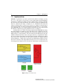
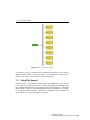
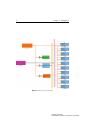
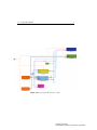
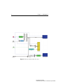
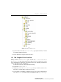
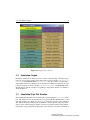
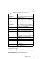
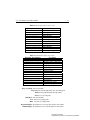
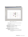
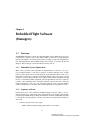
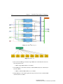
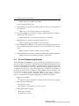
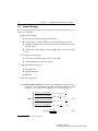
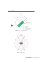
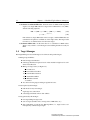
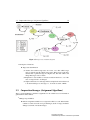
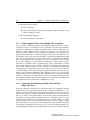
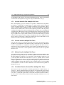
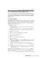
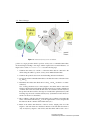
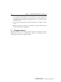
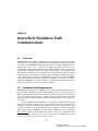
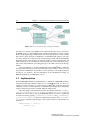
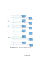
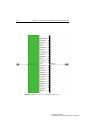
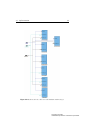
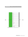
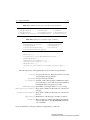
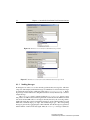
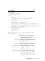
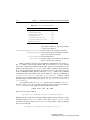
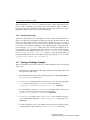

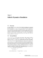
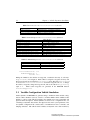
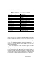
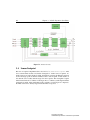
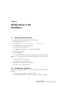
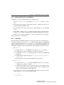
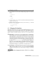
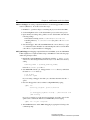
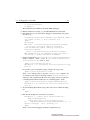
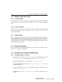
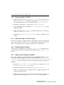
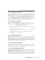
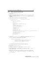
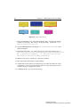

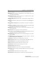
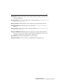


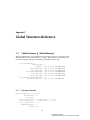
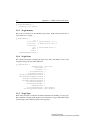
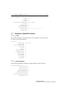
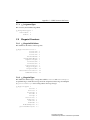
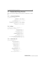


![[U4.42.07] Opérateur DEFI_MATER_GC](http://vs1.manualzilla.com/store/data/006379121_1-bcf03859f7bf5cf9d391bb34e8d8b3a5-150x150.png)