1
20G302-00 E2 – 2013-12-12
User Manual
G302 – 3U CompactPCI®
Serial Industrial Ethernet
Switch
Configuration example
G302 – 3U CompactPCI® Serial Industrial Ethernet Switch
G302 – 3U CompactPCI® Serial Industrial Ethernet Switch
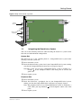
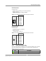
The G302 is a managed 3U Ethernet switch implemented as a CompactPCI® Serial
board. It occupies one system slot or one peripheral slot, using a 4 HP front panel
with 3 Gigabit Ethernet ports on RJ45 or M12 connectors and one service interface
via M12.
The G302 either features three Ethernet ports on the front and up to 13 Ethernet
ports on the rear or alternatively all 16 Ethernet ports on the rear, which is the ideal
solution for conduction cooling.
The G302 supports full-duplex and half-duplex operation with auto-negotiation,
high-speed non-blocking store-and-forward switching, Quality of Service (QoS)
support with four traffic classes IEEE 802.1p and three-level 802.1x security.
The switch is fault tolerant and restores itself on its own: If a link is temporarily
unavailable, frames can be sent via backup/redundant links (spanning tree protocol/
link aggregation) and no data loss occurs. Its built-in test mechanisms make the
G302 an even more reliable component in the communication system.
The railway Ethernet switch is specifically designed for rugged mobile
communication systems and fully compliant with the EN 50155 railway standard,
qualified for a -40 to +85°C operation temperature and ready for coating.
MEN Mikro Elektronik GmbH
20G302-00 E2 – 2013-12-12
2
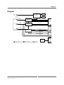
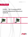
Diagram
Diagram
Service F
Port
DDR2
RGMII
4 x Gb Eth
RGMII
Port 2
F
Switch Device
10/100/
1000Base‐T
Gb Eth
4 x Gb Eth
R
RGMII
Port 3
F
CompactPCI®
Serial P6
Switch Device
10/100/
1000Base‐T
Gb Eth
Gb Eth
4 x Gb Eth
Switch Device
10/100/
1000Base‐T
CompactPCI® Serial P5
F
R
1 x Gb Eth
3 x Gb Eth
CompactPCI® Serial P4
RJ45 or M12 connectors
Port 1
Flash
Management CPU
Power Supply
F
Front connector
MEN Mikro Elektronik GmbH
20G302-00 E2 – 2013-12-12
R
Rear I/O connector
Options
CompactPCI® Serial P1
R
R
3
Technical Data
Technical Data
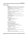
Key Features
• Simple Switch replacement: configuration can be done via external dongle
without any tools
• High-speed non-blocking, store-and-forward switching
• Up to three 10/100/1000Base-T ports at front panel (Electrical isolation:
1500 Vrms)
• Up to sixteen 10/100/1000Base-T ports at rear connector (Electrical isolation:
100 Vrms)
• Port configuration: copper, 10/100 and 1000 Mbit/s
• Auto-negotiation / Auto MDI/MDIX crossover on all ports / manual configuration possible
• Layer2-based Policy Control List
• 8K MAC address lookup table with automatic learning and aging
• Up to 4096 VLANs
• Rapid Spanning Tree Protocol and Multiple Spanning Tree Protocol to ensure
loop free topology formation
• Reducing multicast traffic in the network through multicast snooping – IGS
(IPv4) and MLDS (IPv6)
Management CPU
• Freescale™ PowerPC® MPC8314
- 266 MHz maximum processor core frequency
• 512 MB SDRAM
- DDR2 Management CPU memory
• 32 MB Flash
- Management CPU Flash
Management Firmware System Features
•
•
•
•
•
•
Saving and restoring user configurations
Software upgrades through TFTP
System logs (syslog) and e-mail alerts for critical events
Remote monitoring (RMON) and alarm generation
Displaying the running configuration in the form of CLI commands
Management interfaces through
- CLI (RS232 console, Telnet, SSH)
- SNMP v3
• Switch configuration can be loaded from external dongle
Management Firmware Security Features
• User authentication using 802.1x
• Controlling management access through SNMP and CLI only from authorized
managers
• MAC based access list (ACL) for traffic filtering
• Rate-limiting and storm control to prevent packet flooding from malicious peers
MEN Mikro Elektronik GmbH
20G302-00 E2 – 2013-12-12
4
Technical Data
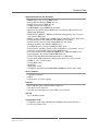
Supported Protocols and Standards
•
•
•
•
•
•
•
•
•
•
•
•
•
•
•
•
•
•
•
•
•
•
DHCP client / server / relay (IEEE 1394)
Energy Efficient Ethernet (IEEE 802.3az)
Ethernet flow control (IEEE 802.3x)
GARP (VLAN-aware bridging)
GVRP/GMRP support (IEEE 802.1D, 2004)
Hypertext Transport Protocol (HTTP) Server for Remote Management and
Monitoring (RFC2626)
HTTP Secure (HTTPS) – HTTP-based Remote Management over encrypted
data channel (RFC2818)
IGMP snooping / IGMP proxy / IGMP Querier / MLD Discovery (RFC 4541)
Link aggregation LACP / EtherChannel (IEEE 802.3ad, 2005)
Link Layer Discovery Protocol LLDP (IEEE 802.1ab, 2005)
Multiple Spanning Tree (MSTP) (IEEE 802.1s)
Path MTU Discovery Protocol (PMTUD) (RFC 1984)
Priority-based switching, Quality of Service/DiffServ, tagged frames, Layer2based 801.1Q VLAN-ID packet routing (IEEE 802.1p)
Port-based authentication with EAP (IEEE 802.1x – REV2004/RFC3748)
Rapid Spanning Tree Protocol (RSTP IEEE 802.1w)
Remote Network Monitoring Information Base v1 (RFC2819)
Secure Shell (SSH) for Remote Configuration (CLI) over secure channel
SNMP v1, v2c, v3 management
Syslog (RFC 5424)
TCP/IP v4
TFTP (RFC 1350)
VLAN/port-based VLANs GVRP/MVRP (IEEE 802.1Q Rev D5.0, 2005)
Service Interface
• 8-pin M12 connector
• RS232
• I2C interface for external dongle
Front I/O
• Three Ethernet ports on RJ45 or M12 connectors
• One M12 service connector
• Six link and activity Ethernet status LEDs (2 per channel)
Rear I/O
• Up to 16 Ethernet links
CompactPCI® Serial
• Compliance with CompactPCI® Serial PICMG CPCI-S.0 Specification
• System or peripheral slot
MEN Mikro Elektronik GmbH
20G302-00 E2 – 2013-12-12
5
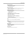
Technical Data
Electrical Specifications
• Supply voltage/power consumption
- +12 V (+/-10%), 15 W max.
Mechanical Specifications
• Dimensions: conforming to CompactPCI® Serial specification for 3U boards
• Front panel: 4HP with ejector
• Weight: 170 g (with RJ45 connectors)/tbd g (with M12 connectors)
Environmental Specifications
• Temperature range (operation):
- -40..+85°C (qualified)
- Airflow: 1.0 m/s
• Temperature range (storage): -40..+85°C
• Relative humidity (operation): max. 95% non-condensing
• Relative humidity (storage): max. 95% non-condensing
• Altitude: -300 m to +3000 m
• Shock: 50 m/s², 30 ms (EN 61373)
• Vibration (function): 1 m/s², 5 Hz – 150 Hz (EN 61373)
• Vibration (lifetime): 7.9 m/s², 5 Hz – 150 Hz (EN 61373)
• Conformal coating on request
• Climatic tests according to EN 68068
• Fully EN 50155-compliant (Power Interruption Class 2, Temperature Class Tx)
MTBF
• 612 519 h @ 40°C according to IEC/TR 62380 (RDF 2000)
Safety
• Flammability
- PCB manufactured with a flammability rating of 94V-0 by UL recognized
manufacturers
EMC Conformity
• EN 55022 (radio disturbance)
• EN61000-4-2 (ESD Immunity)
• IEC 61000-4-4 (burst)
Software Support
• Firmware for configuration and management
MEN Mikro Elektronik GmbH
20G302-00 E2 – 2013-12-12
6
Configuration Options
Configuration Options
Ethernet Switch
• Unmanaged version G303
Front Connectors
• RJ45 connectors or M12 connectors
Front I/O, Rear I/O
• Flexible combination of front and rear ports
- Three ports on front and up to 13 ports on rear
- Up to 16 ports on rear (suitable for conduction cooled version)
- Service port on rear for the conduction cooled version
Environmental specifications
• Conformal coating
Cooling Concept
• Also available with conduction cooling in MEN CCA frame
Please note that some of these options may only be available for large volumes.
Please ask our sales staff for more information.
For available standard configurations see online data sheet.
MEN Mikro Elektronik GmbH
20G302-00 E2 – 2013-12-12
7
Product Safety
Product Safety
!
Electrostatic Discharge (ESD)
Computer boards and components contain electrostatic sensitive devices.
Electrostatic discharge (ESD) can damage components. To protect the board and
other components against damage from static electricity, you should follow some
precautions whenever you work on your computer.
• Power down and unplug your computer system when working on the inside.
• Hold components by the edges and try not to touch the IC chips, leads, or circuitry.
• Use a grounded wrist strap before handling computer components.
• Place components on a grounded antistatic pad or on the bag that came with the
component whenever the components are separated from the system.
• Store the board only in its original ESD-protected packaging. Retain the original
packaging in case you need to return the board to MEN for repair.
MEN Mikro Elektronik GmbH
20G302-00 E2 – 2013-12-12
8
About this Document
About this Document
This user manual is intended only for system developers and integrators, it is not
intended for end users.
It describes the hardware functions of the board, connection of peripheral devices
and integration into a system. It also provides additional information for special
applications and configurations of the board.
The manual does not include detailed information on individual components (data
sheets etc.). A list of literature is given in the appendix.
History
Issue
Comments
Date
E1
First issue
2012-10-06
E2
General update
2013-12-12
Conventions
This sign marks important notes or warnings concerning the use of voltages which
can lead to serious damage to your health and also cause damage or destruction of
the component.
!
italics
bold
monospace
This sign marks important notes or warnings concerning proper functionality of the
product described in this document. You should read them in any case.
Folder, file and function names are printed in italics.
Bold type is used for emphasis.
A monospaced font type is used for hexadecimal numbers, listings, C function
descriptions or wherever appropriate. Hexadecimal numbers are preceded by "0x".
comment
Comments embedded into coding examples are shown in green color.
hyperlink
Hyperlinks are printed in blue color.
The globe will show you where hyperlinks lead directly to the Internet, so you can
look for the latest information online.
IRQ#
/IRQ
Signal names followed by "#" or preceded by a slash ("/") indicate that this signal is
either active low or that it becomes active at a falling edge.
in/out
Signal directions in signal mnemonics tables generally refer to the corresponding
board or component, "in" meaning "to the board or component", "out" meaning
"coming from it".
Vertical lines on the outer margin signal technical changes to the previous issue of
the document.
MEN Mikro Elektronik GmbH
20G302-00 E2 – 2013-12-12
9
About this Document
Legal Information
Changes
MEN Mikro Elektronik GmbH ("MEN") reserves the right to make changes without further notice to any products
herein.
Warranty, Guarantee, Liability
MEN makes no warranty, representation or guarantee of any kind regarding the suitability of its products for any
particular purpose, nor does MEN assume any liability arising out of the application or use of any product or
circuit, and specifically disclaims any and all liability, including, without limitation, consequential or incidental
damages. TO THE EXTENT APPLICABLE, SPECIFICALLY EXCLUDED ARE ANY IMPLIED
WARRANTIES ARISING BY OPERATION OF LAW, CUSTOM OR USAGE, INCLUDING WITHOUT
LIMITATION, THE IMPLIED WARRANTIES OF MERCHANTABILITY AND FITNESS FOR A
PARTICULAR PURPOSE OR USE. In no event shall MEN be liable for more than the contract price for the
products in question. If buyer does not notify MEN in writing within the foregoing warranty period, MEN shall
have no liability or obligation to buyer hereunder.
The publication is provided on the terms and understanding that:
1. MEN is not responsible for the results of any actions taken on the basis of information in the publication, nor
for any error in or omission from the publication; and
2. MEN is not engaged in rendering technical or other advice or services.
MEN expressly disclaims all and any liability and responsibility to any person, whether a reader of the publication
or not, in respect of anything, and of the consequences of anything, done or omitted to be done by any such person
in reliance, whether wholly or partially, on the whole or any part of the contents of the publication.
Conditions for Use, Field of Application
The correct function of MEN products in mission-critical and life-critical applications is limited to the
environmental specification given for each product in the technical user manual. The correct function of MEN
products under extended environmental conditions is limited to the individual requirement specification and
subsequent validation documents for each product for the applicable use case and has to be agreed upon in writing
by MEN and the customer. Should the customer purchase or use MEN products for any unintended or
unauthorized application, the customer shall indemnify and hold MEN and its officers, employees, subsidiaries,
affiliates, and distributors harmless against all claims, costs, damages, and expenses, and reasonable attorney fees
arising out of, directly or indirectly, any claim or personal injury or death associated with such unintended or
unauthorized use, even if such claim alleges that MEN was negligent regarding the design or manufacture of the
part. In no case is MEN liable for the correct function of the technical installation where MEN products are a part
of.
Trademarks
All products or services mentioned in this publication are identified by the trademarks, service marks, or product
names as designated by the companies which market those products. The trademarks and registered trademarks
are held by the companies producing them. Inquiries concerning such trademarks should be made directly to those
companies.
Conformity
MEN products are no ready-made products for end users. They are tested according to the standards given in the
Technical Data and thus enable you to achieve certification of the product according to the standards applicable in
your field of application.
MEN Mikro Elektronik GmbH
20G302-00 E2 – 2013-12-12
10
About this Document
RoHS
Since July 1, 2006 all MEN standard products comply with RoHS legislation.
Since January 2005 the SMD and manual soldering processes at MEN have already been completely lead-free.
Between June 2004 and June 30, 2006 MEN’s selected component suppliers have changed delivery to RoHScompliant parts. During this period any change and status was traceable through the MEN ERP system and the
boards gradually became RoHS-compliant.
WEEE Application
The WEEE directive does not apply to fixed industrial plants and tools. The compliance is the responsibility of the
company which puts the product on the market, as defined in the directive; components and sub-assemblies are
not subject to product compliance.
In other words: Since MEN does not deliver ready-made products to end users, the WEEE directive is not
applicable for MEN. Users are nevertheless recommended to properly recycle all electronic boards which have
passed their life cycle.
Nevertheless, MEN is registered as a manufacturer in Germany. The registration number can be provided on
request.
Copyright © 2013 MEN Mikro Elektronik GmbH. All rights reserved.
Germany
MEN Mikro Elektronik GmbH
Neuwieder Straße 3-7
90411 Nuremberg
Phone +49-911-99 33 5-0
Fax +49-911-99 33 5-901
E-mail [email protected]
www.men.de
MEN Mikro Elektronik GmbH
20G302-00 E2 – 2013-12-12
France
MEN Mikro Elektronik SA
18, rue René Cassin
ZA de la Châtelaine
74240 Gaillard
Phone +33 (0) 450-955-312
Fax +33 (0) 450-955-211
E-mail [email protected]
www.men-france.fr
USA
MEN Micro Inc.
860 Penllyn Blue Bell Pike
Blue Bell, PA 19422
Phone (215) 542-9575
Fax (215) 542-9577
E-mail [email protected]
www.menmicro.com
11
Contents
Contents
1 Getting Started . . . . . . . . . . . . . . . . . . . . . . . . . . . . . . . . . . . . . . . . . . . . . . . .
1.1 Map of the Board. . . . . . . . . . . . . . . . . . . . . . . . . . . . . . . . . . . . . . . . .
1.2 Integrating the Board into a System . . . . . . . . . . . . . . . . . . . . . . . . . .
1.3 Installing Driver Software . . . . . . . . . . . . . . . . . . . . . . . . . . . . . . . . . .
14
14
15
16
2 Functional Description . . . . . . . . . . . . . . . . . . . . . . . . . . . . . . . . . . . . . . . . . .
2.1 Power Supply. . . . . . . . . . . . . . . . . . . . . . . . . . . . . . . . . . . . . . . . . . . .
2.2 Thermal Considerations. . . . . . . . . . . . . . . . . . . . . . . . . . . . . . . . . . . .
2.3 Ethernet Interface . . . . . . . . . . . . . . . . . . . . . . . . . . . . . . . . . . . . . . . .
2.3.1
Front-Panel Connection . . . . . . . . . . . . . . . . . . . . . . . . . . . .
2.3.2
Front Panel Status LEDs . . . . . . . . . . . . . . . . . . . . . . . . . . . .
2.3.3
Ethernet Switch . . . . . . . . . . . . . . . . . . . . . . . . . . . . . . . . . . .
2.3.4
Configuration of the Switch . . . . . . . . . . . . . . . . . . . . . . . . .
2.4 Service Connector . . . . . . . . . . . . . . . . . . . . . . . . . . . . . . . . . . . . . . . .
2.5 CompactPCI Serial Interface . . . . . . . . . . . . . . . . . . . . . . . . . . . . . . . .
17
17
17
17
17
18
19
19
20
21
3 Appendix . . . . . . . . . . . . . . . . . . . . . . . . . . . . . . . . . . . . . . . . . . . . . . . . . . . . .
3.1 Literature and Web Resources . . . . . . . . . . . . . . . . . . . . . . . . . . . . . . .
3.1.1
Ethernet . . . . . . . . . . . . . . . . . . . . . . . . . . . . . . . . . . . . . . . . .
3.1.2
CompactPCI Serial . . . . . . . . . . . . . . . . . . . . . . . . . . . . . . . .
3.2 Finding out the Product’s Article Number, Revision and
Serial Number . . . . . . . . . . . . . . . . . . . . . . . . . . . . . . . . . . . . . . . . . . .
24
24
24
24
MEN Mikro Elektronik GmbH
20G302-00 E2 – 2013-12-12
24
12
Figures
Figure 1. Map of the board – front panels with RJ45 ports (left) or
M12 ports (right) . . . . . . . . . . . . . . . . . . . . . . . . . . . . . . . . . . . . . . . . . 14
Figure 2. Map of the board – top view. . . . . . . . . . . . . . . . . . . . . . . . . . . . . . . . . 15
Figure 3. Labels giving the product’s article number, revision and
serial number . . . . . . . . . . . . . . . . . . . . . . . . . . . . . . . . . . . . . . . . . . . . 24
Tables
Table 1.
Table 2.
Table 3.
Table 4.
Table 5.
Table 6.
Table 7.
Table 8.
Table 9.
Table 10.
Table 11.
MEN Mikro Elektronik GmbH
20G302-00 E2 – 2013-12-12
Signal mnemonics of Ethernet front-panel connectors. . . . . . . . . . . . .
Pin assignment of RJ45 Ethernet front-panel connectors. . . . . . . . . . .
Pin assignment of M12 Ethernet front-panel connectors . . . . . . . . . . .
Ethernet ports status LEDs . . . . . . . . . . . . . . . . . . . . . . . . . . . . . . . . . .
Default switch configuration at startup . . . . . . . . . . . . . . . . . . . . . . . .
Signal mnemonics of front-panel service connector . . . . . . . . . . . . . .
Pin assignment of front-panel service connector . . . . . . . . . . . . . . . . .
Pin assignment of CompactPCI Serial P1 connector . . . . . . . . . . . . . .
Pin assignment of CompactPCI Serial P6 connector . . . . . . . . . . . . . .
Pin assignment of CompactPCI Serial P5 connector . . . . . . . . . . . . . .
Pin assignment of CompactPCI Serial P4 connector . . . . . . . . . . . . . .
18
19
19
19
20
21
21
22
23
23
24
13
Getting Started
1
Getting Started
This chapter gives an overview of the board and some hints for first installation in a
system.
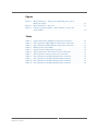
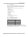
1.1
Map of the Board
Two types of front panels are available, either with three RJ45 Ethernet connectors
or with three M12 Ethernet connectors.
Figure 1. Map of the board – front panels with RJ45 ports (left) or M12 ports (right)
®
®
A
L
A
L
1
1
SERVICE
SERVICE
X1
X1
X2
X2
X3
X3
MEN Mikro Elektronik GmbH
20G302-00 E2 – 2013-12-12
2
3
2
3
G302
G302
14
Getting Started
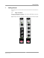
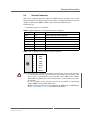
Figure 2. Map of the board – top view
P6
Service connector
1
X1
RJ45 or M12 connectors
X2
X3
1
1.2
P1
Integrating the Board into a System
You can use the following check list when installing the board in a system for the
first time and with minimum configuration.
System Slot
The G302 can act as the switching hub of a CompactPCI Serial system when
inserting it into the system slot.
Power down the system.
Insert the G302 into the system slot of your CompactPCI Serial system, making
sure that the CompactPCI Serial connectors are properly aligned.
Note:The system slot of every CompactPCI Serial system is marked by a
triangle
on the backplane and/or at the front panel. It also has red
guide rails.
Power up the system.
Peripheral Slot
Power down the system.
Insert the G302 into a peripheral slot of your CompactPCI Serial system,
making sure that the CompactPCI Serial connectors are properly aligned.
Note: The peripheral slots of every CompactPCI Serial system are marked by a
circle with a plus sign behind it on the backplane and/or at the front
panel.
Power up the system.
MEN Mikro Elektronik GmbH
20G302-00 E2 – 2013-12-12
15
Getting Started
1.3
Installing Driver Software
For a detailed description on how to install driver software please refer to the
respective documentation.
You can find any driver software available for download in the G302 pages on
MEN’s website.
MEN Mikro Elektronik GmbH
20G302-00 E2 – 2013-12-12
16
Functional Description
2
Functional Description
2.1
Power Supply
The G302 is supplied with +12V (-10%/+10%) via CompactPCI Serial connector P1.
2.2
Thermal Considerations
A suitable heat sink is provided to meet thermal requirements.
!
Please note that if you use any other heat sink than that supplied by MEN, or no heat
sink at all, warranty on functionality and reliability of the G302 may cease. If you
have any questions or problems regarding thermal behavior, please contact MEN.
2.3
Ethernet Interface
Depending on the configuration the G302 has up to 16 Gigabit Ethernet interfaces.
It is either possible to have three Ethernet interfaces at the front and up to 13
Ethernet interfaces on the rear or to have up to 16 Ethernet interfaces on the rear.
The G302 standard model provides three Ethernet ports on the front and eight on the
rear. All channels support 10/100/1000Base-T physical layers, and half-duplex and
full-duplex operation complying with IEEE802.3x.
!
The unique MAC addresses are set at the factory and should not be changed. Any
attempt to change these addresses may create node or bus contention and thereby
render the board inoperable.
2.3.1
Front-Panel Connection
The G302 is available in two versions: one provides three standard RJ45 connectors
(standard version) and one three 8-pin M12 connectors at the front panel.
The pin assignments correspond to the Ethernet specification IEEE802.3
Table 1. Signal mnemonics of Ethernet front-panel connectors
Signal
BI_Dx+/-
MEN Mikro Elektronik GmbH
20G302-00 E2 – 2013-12-12
Direction
in/out
Function
Differential pairs of data lines for 1000Base-T
17
Functional Description
RJ45 Connectors
Connector types:
• Modular 8/8-pin mounting jack according to FCC68
• Mating connector:
Modular 8/8-pin plug according to FCC68
Table 2. Pin assignment of RJ45 Ethernet front-panel connectors
1000Base-T
1
8
1
BI_DA+
2
BI_DA-
3
BI_DB+
4
BI_DC+
5
BI_DC-
6
BI_DB-
7
BI_DD+
8
BI_DD-
M12 Connectors
Connector types:
• 8-pin M12 receptacle A-coded 90°
• Mating connector:
8-pin M12 plug A-coded 90°
Table 3. Pin assignment of M12 Ethernet front-panel connectors
1000Base-T
7
8
1
2
6
5
1
BI_DC-
2
BI_DD+
3
BI_DD-
4
BI_DA-
5
BI_DB+
6
BI_DA+
7
BI_DC+
8
BI_DB-
3
4
2.3.2
Front Panel Status LEDs
The front panel features two LEDs for each of the three Ethernet ports to display
their status (LNK and ACT). The LEDs act as described in the following table.
Table 4. Ethernet ports status LEDs
LED
L
Ethernet link status (on = link established)
A
Ethernet traffic activity status (blink = Ethernet traffic running)
MEN Mikro Elektronik GmbH
20G302-00 E2 – 2013-12-12
Description
18
Functional Description
2.3.3
Ethernet Switch
The G302 uses two 7-port 10/100/1000Base-T switch components Marvell
88E6176. The switch provides 10/100/1000 Mbits/s configuration possibility on
each port. It is possible to configure each port in half-duplex or full-duplex mode.
The device characteristics are:
•
•
•
•
•
•
•
•
•
•
•
•
Three front ports and up to 13 ports on the rear or up to 16 ports on the rear
RGMII interface
High-speed non-blocking
Store-and-forward switching
Auto-negotiation
Quality of Service (QoS) support
Port mirroring
Port monitoring
Flow control
VLAN support
Automatic MDI/MDI-X crossover (all ports)
Port-based frame priorization
2.3.4
Configuration of the Switch
The G302 loads the following standard configuration at startup:
Table 5. Default switch configuration at startup
Setting
Default
Duplex mode
Full Duplex
Port speed
Auto-Negotiate
VLAN (port-based)
Off
QoS (Quality of Service)
Off
Port mirroring and port monitoring
Off
Port trunking
Off
All of the ports are individually configurable using an external dongle, a Telnet or
Secure Shell (SSH) command line interface via the M12 service connector or over
Ethernet via SNMP (Version 3). For further information about configuration options
please refer to the documentation of the G302 firmware.
MEN Mikro Elektronik GmbH
20G302-00 E2 – 2013-12-12
19
Functional Description
2.4
Service Connector
The service connector provides an RS-232 COM interface for direct access to the
management CPU and an I2C interface for reading a configuration from an external
dongle (available from MEN), which can be connected to this interface.
Connector type:
• 8-pin M12 receptacle A-coded 90°
Table 6. Signal mnemonics of front-panel service connector
Signal
Direction
Function
+3.3V
out
Power supply for external dongle
GND
-
Ground
RXD
in
RS232 receive data
TXD
out
RS232 transmit data
SDA
in/out
I2C serial data input/output
SCL
-
I2C data clock
GPIO[1:2]
in/out
General purpose I/O 1/2
Table 7. Pin assignment of front-panel service connector
7
8
1
2
6
5
!
+3.3V
2
RXD
3
TXD
4
GND
5
SDA
6
GPIO1
7
SCL
8
GPIO2
3
4
Note: Do not connect a standard null modem cable directly to the service interface
as it blocks the I2C bus and prevents the switch from correct booting. You
always need a 9-pin D-Sub to 9-pin 2xD-Sub cable (MEN article number
6080-0366) for splitting the service interface into a serial interface and a dongle interface.
In case of an M12 service interface you need an 8-pin M12 to 9-pin D-Sub
adapter (MEN article number 6080-0377).
Both the adapter and the cable are included in the MEN cable set 05RS01-03.
Please contact MEN’s sales team for further information.
MEN Mikro Elektronik GmbH
20G302-00 E2 – 2013-12-12
1
20
Functional Description
2.5
CompactPCI Serial Interface
The G302 uses the rear connectors P1 and P6 according to the CompactPCI Serial
specification (PICMG CPCI-S.0). Optionally the G302 can be supplied with
connector P5 if up to 15 Ethernet ports are required or with connectors P5 and P4 if
16 Ethernet ports are required or if more than 12 ports are required on the rear.
Pin Assignment of Connector P1
Connector type of P1:
• 72-pin Airmax VS 4 pair, right angle header, 6 IMLA with end walls
Table 8. Pin assignment of CompactPCI Serial P1 connector
A
1
PE_
Rx03-
PE_
Rx03+
GND
PE_
Tx03-
PE_
Tx03+
GND
PE_
Rx02-
PE_
Rx02+
GND
PE_
Tx02-
PE_
Tx02+
GND
6
GND
PE_
Rx01-
PE_
Rx01+
GND
PE_
Tx01-
PE_
Tx01+
GND
PE_
Rx00-
PE_
Rx00+
GND
PE_
Tx00-
PE_
Tx00+
5
GND
1_USB2-
1_USB2
+
GND
4
1_SATA_ 1_SATA_
RxRx+
GND
1_SATA_ 1_SATA
Tx_Tx+
GND
SATA_S SATA_
DO
SDI
PE_
PE_
REFCLK- REFCLK+
GA3
SATA_S
L
SATA_
SCL
GA2
SYSEN#
PCIE_
EN#
GND
PE_
WAKE#
RST_
IN#
GND
RST_
OUT#
PS_ON#
GND
IPMB_S
DA
IPMB_
SCL
GND
2
GND
+12V
+12V
GND
+12V
+12V
GND
+12V
+12V
GND
STNDBY
+12V
1
L
K
J
I
H
G
F
E
D
C
B
A
GA1
1_USB3_ 1_USB3_
RxRx+
GA0
1_USB3 1_USB3
_Tx_Tx+
3
Note: The signals in gray font are specified in the CompactPCI Serial specification
but not supported on this board.
MEN Mikro Elektronik GmbH
20G302-00 E2 – 2013-12-12
21
Functional Description
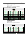
Pin Assignment of Connector P6
Connector type of P6:
96-pin Airmax VS 4 pair, right angle header, 8 rows, 4 walls
Table 9. Pin assignment of CompactPCI Serial P6 connector
1
A
8_ETH_ 8_ETH_
DD+
GND
7_ETH_ 7_ETH_
DD+
6_ETH_ 6_ETH_
DD+
GND
L
GND
3_ETH_ 3_ETH_
DD+
2_ETH_ 2_ETH_
DD+
GND
GND
5_ETH_ 5_ETH_
DD+
4_ETH_ 4_ETH_
DD+
GND
GND
GND
1_ETH_ 1_ETH_
DD+
K
8_ETH_ 8_ETH_
CC+
GND
7_ETH_ 7_ETH_
CC+
6_ETH_ 6_ETH_
CC+
GND
J
I
GND
3_ETH_ 3_ETH_
CC+
2_ETH_ 2_ETH_
CC+
GND
GND
5_ETH_ 5_ETH_
CC+
4_ETH_ 4_ETH_
CC+
GND
GND
GND
1_ETH_ 1_ETH_
CC+
H
G
8_ETH_ 8_ETH_
BB+
GND
7_ETH_ 7_ETH_
BB+
GND
6_ETH_ 6_ETH_
BB+
GND
5_ETH_ 5_ETH_
BB+
GND
4_ETH_ 4_ETH_
BB+
GND
3_ETH_ 3_ETH_
BB+
GND
2_ETH_ 2_ETH_
BB+
GND
1_ETH_ 1_ETH_
BB+
GND
F
E
D
8_ETH_ 8_ETH_
AA+
GND
7_ETH_ 7_ETH_
AA+
6_ETH_ 6_ETH_
AA+
GND
C
GND
3_ETH_ 3_ETH_
AA+
2_ETH_ 2_ETH_
AA+
GND
GND
5_ETH_ 5_ETH_
AA+
4_ETH_ 4_ETH_
AA+
GND
GND
GND
1_ETH_ 1_ETH_
AA+
B
8
7
6
5
4
3
2
1
A
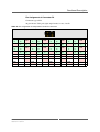
Pin Assignment of Connector P5
Connector type of P5:
96-pin Airmax VS 4 pair, right angle header, 6 rows, 2 walls
Table 10. Pin assignment of CompactPCI Serial P5 connector
1
A
9_ETH_ 9_ETH_
DD+
GND
10_ETH_ 10_ETH_
DD+
11_ETH_ 11_ETH_
DD+
GND
GND
GND
12_ETH_ 12_ETH_
DD+
9_ETH_ 9_ETH_
CC+
GND
-
-
GND
-
GND
GPIO2
+3.3V
GND
L
K
J
I
MEN Mikro Elektronik GmbH
20G302-00 E2 – 2013-12-12
10_ETH_ 10_ETH_
CC+
11_ETH_ 11_ETH_
CC+
GND
GND
GND
12_ETH_ 12_ETH_
CC+
-
GND
I2C_SCL I2C_SDA
H
G
9_ETH_ 9_ETH_
BB+
GND
10_ETH_ 10_ETH_
BB+
11_ETH_ 11_ETH_
BB+
GND
GND
F
GND
GND
12_ETH_ 12_ETH_
BB+
-
GND
COM_RX COM_TX
E
D
9_ETH_ 9_ETH_
AA+
GND
10_ETH_ 10_ETH_
AA+
11_ETH_ 11_ETH_
AA+
GND
GND
GND
12_ETH_ 12_ETH_
AA+
6
5
4
3
-
-
GND
2
GND
+3.3V
GPIO1
1
C
B
A
22
Functional Description
Pin Assignment of Connector P4
Connector type of P4:
96-pin Airmax VS 4 pair, right angle header, 8 rows, 4 walls
Table 11. Pin assignment of CompactPCI Serial P4 connector
1
A
13_ETH_ 13_ETH_
DD+
GND
14_ETH_ 14_ETH_
DD+
15_ETH_ 15_ETH_
DD+
GND
GND
GND
16_ETH_ 16_ETH_
DD+
13_ETH_ 13_ETH_
CC+
GND
14_ETH_ 14_ETH_
CC+
15_ETH_ 15_ETH_
CC+
GND
GND
GND
16_ETH_ 16_ETH_
CC+
13_ETH_ 13_ETH_
BB+
GND
14_ETH_ 14_ETH_
BB+
15_ETH_ 15_ETH_
BB+
GND
GND
GND
16_ETH_ 16_ETH_
BB+
13_ETH_ 13_ETH_
AA+
GND
14_ETH_ 14_ETH_
AA+
15_ETH_ 15_ETH_
AA+
GND
GND
GND
16_ETH_ 16_ETH_
AA+
8
7
6
5
-
-
GND
-
-
GND
-
-
GND
-
-
GND
4
GND
-
-
GND
-
-
GND
-
-
GND
-
-
3
-
-
GND
-
-
GND
-
-
GND
-
-
GND
2
GND
-
-
GND
-
-
GND
-
-
GND
-
-
1
L
K
J
I
H
G
F
E
D
C
B
A
MEN Mikro Elektronik GmbH
20G302-00 E2 – 2013-12-12
23
Appendix
3
Appendix
3.1
Literature and Web Resources
• G302 data sheet with up-to-date information and documentation:
www.men.de/products/02G302-.html
3.1.1
Ethernet
• ANSI/IEEE 802.3-1996, Information Technology - Telecommunications and
Information Exchange between Systems - Local and Metropolitan Area Networks - Specific Requirements - Part 3: Carrier Sense Multiple Access with Collision Detection (CSMA/CD) Access Method and Physical Layer Specifications;
1996; IEEE
www.ieee.org
• Charles Spurgeon's Ethernet Web Site
Extensive information about Ethernet (IEEE 802.3) local area network (LAN)
technology.
www.ethermanage.com/ethernet/
• InterOperability Laboratory, University of New Hampshire
This page covers general Ethernet technology.
www.iol.unh.edu/services/testing/ethernet/training/
3.1.2
CompactPCI Serial
• CompactPCI Serial Specification PICMG CPCI-S.0 Revision 1.0:
2011; PCI Industrial Computers Manufacturers Group (PICMG)
www.picmg.org
• Introduction to CompactPCI Serial on Wikipedia:
en.wikipedia.org/wiki/CompactPCI_Serial
3.2
Finding out the Product’s Article Number, Revision and
Serial Number
MEN user documentation may describe several different models and/or design
revisions of the G302. You can find information on the article number, the design
revision and the serial number on two labels attached to the board.
• Article number: Gives the product’s family and model. This is also MEN’s
ordering number. To be complete it must have 9 characters.
• Revision number: Gives the design revision of the product.
• Serial number: Unique identification assigned during production.
If you need support, you should communicate these numbers to MEN.
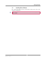
Figure 3. Labels giving the product’s article number, revision and serial number
Complete article number
02G302-00
00.00.00
Revision number
MEN Mikro Elektronik GmbH
20G302-00 E2 – 2013-12-12
Serial number
24