1
Embedded Solutions
20F302-00 E4 – 2010-12-16
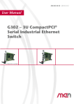
F302 – 3U CompactPCI 8+1-Port
Managed Ethernet Switch
Configuration example
Configuration example
User Manual
®
F302 – 3U CompactPCI® 8+1-Port Managed Ethernet Switch
F302 – 3U CompactPCI® 8+1-Port Managed Ethernet Switch
The F302 is a managed 3U Fast Ethernet switch module that provides eight
channels at the front panel (8 RJ45 or M12 connectors) plus one additional Ethernet
channel that is led to the CompactPCI® J1 connector at the rear.
The F302 is managed by its own PowerPC CPU that integrates the configuration
firmware. A service interface is accessible at the front panel, providing an easy way
to configure the switch. A command line interface is available via the RS232 at the
service port and over Ethernet via Telnet or Secure Shell (SSH). The switch can also
be configured via SNMP (version 3) and through its HTTP web server. Additionally,
the service connector can be used to attach an external dongle to store or update the
switch configuration. This makes it easy to exchange the unit for service purposes.
The F302 supports full-duplex and half-duplex operation with auto-negotiation,
high-speed non-blocking store-and-forward-switching, Quality of Service (QoS)
support with four traffic classes IEEE 802.1p and three-level 802.1x security as well
as the logical segmentation of ports (802.1q VLANs). The switch is fault tolerant
and restores itself on its own: If a link is temporarily unavailable, frames can be sent
via backup/redundant links (spanning tree protocol / link aggregation) and no data
loss occurs. Its built-in test mechanisms make the F302 an even more reliable
component in the communication system.
The F302 was specifically designed for rugged mobile communication systems. It is
thus for example fully compliant with the EN 50155 railway standard. All
components on the board are specified for a -40 to +85°C operation temperature.
There are no socketed components, hardening the card against shock and vibration.
The board is ready for coating (standard with M12 connectors) and has a guaranteed
minimum standard availability of 5 years.
Depending on the connector type, the F302 has a front-panel width of 12 HP (3
slots) with RJ45 or 16 HP (4 slots) with M12 connectors. In either case the card
occupies only one CompactPCI® backplane slot.
MEN Mikro Elektronik GmbH
20F302-00 E4 – 2010-12-16
2
Technical Data
Technical Data
Switch Fabric Key Features
• Eight 10/100Base-T ports at front panel
- Electrical isolation: 1,500 Vrms
• Ninth 10/100Base-T port via CompactPCI® J1 (rear)
• Auto-negotiation
• High-speed non-blocking, store-and-forward switching
• 8K MAC address lookup table with automatic learning and aging
• Layer 2 switching
• Back pressure or IEEE802.3x flow control
• Automatic MDI/MDI-X crossover (all ports)
Management Firmware System Features
•
•
•
•
•
•
•
Saving and restoring user configurations
Software upgrades through TFTP
System logs (syslog) and e-mail alerts for critical events
Remote monitoring (RMON) and alarm generation
Displaying the running configuration in the form of CLI commands
DHCP client, server and relay
Management interfaces through
- CLI (RS232 console, Telnet, SSH)
- SNMP v3
- WebUI (HTTP and HTTPS/SSL)
• Switch configuration can be loaded from external dongle
Management Firmware Layer 2 Features
•
•
•
•
•
•
•
•
•
•
•
•
TCP/IP (IPv4, IPv6)
Transparent bridging
QoS (DiffServ) and 802.1p traffic prioritization queuing, polishing, shaping
VLAN-aware bridging with GARP
Static and dynamic VLANs (through GVRP)
Dynamic learning of multicast groups through GMRP
Rapid Spanning Tree Protocol and Multiple Spanning Tree Protocol to ensure
loop free topology formation
Reducing multicast traffic in the network through multicast snooping – IGS
(IPv4) and MLDS (IPv6)
IGMP proxy
Aggregating physical ports for increasing bandwidth and redundancy through
link aggregation (LACP)
Link Layer Discovery Protocol (LLDP)
SNMP (v1, v2c, v3) agent and MIB support, configuration save/restore
MEN Mikro Elektronik GmbH
20F302-00 E4 – 2010-12-16
3
Technical Data
Management Firmware Security Features
• User authentication using 802.1x
• Controlling management access through SNMP, CLI and web only from
authorized managers
• MAC based access list (ACL) for traffic filtering
• Rate-limiting and storm control to prevent packet flooding from malicious peers
Supported Ethernet Standards
•
•
•
•
•
•
•
•
•
•
•
•
Transparent bridging: IEEE 802.1D, 2004
VLAN: IEEE 802.1Q Rev D5.0, 2005
Port based VLANs: IEEE 802.1Q Rev D5.0, 2005
GVRP/GMRP support: IEEE 802.1D
Rapid Spanning Tree Protocol: IEEE 802.1D
Multiple Spanning Tree: IEEE 802.1s, IEEE 802.1Q Rev D5.0, 2005
IGMP snooping: draft-ietf-magma-snoop-12.txt
MLD snooping: draft-ietf-magma-snoop-12.txt
Link aggregation: IEEE 802.3ad, 2005
Port based authentification with EAP: IEEE 802.1X – REV2004
Link Layer Discovery Protocol: IEEE 802.1AB, 2005
Priority based switching: IEEE 802.1p
Service Interface
• 9-pin D-Sub connector at front
• RS232 / V24
• I2C interface for external dongle
Front I/O
•
•
•
•
8 Ethernet ports via RJ45 or M12 D connectors
1 service interface via 9-pin D-Sub plug connector
16 link and activity Ethernet status LEDs (2 per channel)
Status LEDs for power, reset and error codes
CompactPCI® Bus
•
•
•
•
•
•
Compliance with CompactPCI® Specification 2.0 R3.0
Only one slot required on the 3U CompactPCI® bus
Peripheral slot
Compliance with PCI Specification 2.1
V(I/O): +3.3 V or +5 V
Ninth Fast Ethernet port via CompactPCI® J1
Electrical Specifications
• Supply voltage:
- +3.3 V (-3%/+5%)
- +5 V (-3%/+5%)
• Power consumption: 5 W (max.)
• MTBF: Approx. 200,000 h @ 40°C according to IEC/TR 62380 (RDF 2000)
MEN Mikro Elektronik GmbH
20F302-00 E4 – 2010-12-16
4
Technical Data
Mechanical Specifications
• Dimensions: conforming to CompactPCI® specification for 3U boards
• Weight: 316 g (16HP model with M12 connectors)
Environmental Specifications
• Temperature range (operation):
- -40..+85°C (qualified components)
- Airflow: min. 10 m³/h
• Temperature range (storage): -40..+85°C
• Relative humidity (operation): max. 95% non-condensing
• Relative humidity (storage): max. 95% non-condensing
• Altitude: -300 m to + 3,000 m
• Shock: according to EN 60068-2-27
• Bump: according to EN 60068-2-29
• Vibration (sinusoidal): according to EN 60068-2-6
• Conformal coating on request (standard with M12 connectors)
Safety
• PCB manufactured with a flammability rating of 94V-0 by UL recognized manufacturers
EMC
• Tested according to EN 55022 (radio disturbance), IEC1000-4-2 (ESD) and
IEC1000-4-4 (burst)
Firmware
• Firmware for configuration and management included
• For more information on supported operating system versions and drivers see
online data sheet.
MEN Mikro Elektronik GmbH
20F302-00 E4 – 2010-12-16
5
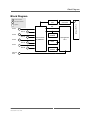
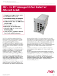
Block Diagram
Block Diagram
F
Front connector
R
Rear I/O connector
Port 9
Ethernet
PHY
PCI‐Ethernet
Controller
CompactPCI® J1
Options
MII
Port 1
F
Port 2
Port 3
Port 5
Port 7
Service
Port
F
Config
EEPROM
F
Port 4
F
Port 6
F
Port 8
F
F
Switch Device
10/100Base‐T
R
Management
CPU
Flash
F
DDR2
SDRAM
F
MEN Mikro Elektronik GmbH
20F302-00 E4 – 2010-12-16
6
Configuration Options
Configuration Options
Front Connectors / Mechanical
• RJ45 connectors
- 12 HP (3-slot) front panel
• M12 D connectors
- 16 HP (4-slot) front panel
Environmental Specifications
• Conformal coating for RJ45 models (standard with M12 connectors)
For available standard configurations see online data sheet.
MEN Mikro Elektronik GmbH
20F302-00 E4 – 2010-12-16
7
Product Safety
Product Safety
!
Electrostatic Discharge (ESD)
Computer boards and components contain electrostatic sensitive devices.
Electrostatic discharge (ESD) can damage components. To protect the board and
other components against damage from static electricity, you should follow some
precautions whenever you work on your computer.
• Power down and unplug your computer system when working on the inside.
• Hold components by the edges and try not to touch the IC chips, leads, or circuitry.
• Use a grounded wrist strap before handling computer components.
• Place components on a grounded antistatic pad or on the bag that came with the
component whenever the components are separated from the system.
• Store the board only in its original ESD-protected packaging. Retain the original
packaging in case you need to return the board to MEN for repair.
MEN Mikro Elektronik GmbH
20F302-00 E4 – 2010-12-16
8
About this Document
About this Document
This user manual describes the hardware functions of the board, connection of
peripheral devices and integration into a system. It also provides additional
information for special applications and configurations of the board.
The manual does not include detailed information on individual components (data
sheets etc.). A list of literature is given in the appendix.
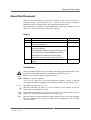
History
Issue
Comments
Date of Issue
E1
First issue
2009-02-16
E2
Major general update based on new hardware and
firmware specification
2010-02-15
E3
Unit also supports +5 V supply voltage, added
power consumption
2010-12-15
Reworked block diagram (connection between CPU
and switch device, config EEPROM connection)
Removed IP-based ACL from technical data
Moved TCP/IP (IPv4, IPv6) to Layer 2 features
E4
Slight changes to clarify support of +5 V supply
voltage
2010-12-16
Conventions
!
italics
bold
monospace
hyperlink
This sign marks important notes or warnings concerning proper functionality of the
product described in this document. You should read them in any case.
Folder, file and function names are printed in italics.
Bold type is used for emphasis.
A monospaced font type is used for hexadecimal numbers, listings, C function
descriptions or wherever appropriate. Hexadecimal numbers are preceded by "0x".
Hyperlinks are printed in blue color.
The globe will show you where hyperlinks lead directly to the Internet, so you can
look for the latest information online.
IRQ#
/IRQ
Signal names followed by "#" or preceded by a slash ("/") indicate that this signal is
either active low or that it becomes active at a falling edge.
in/out
Signal directions in signal mnemonics tables generally refer to the corresponding
board or component, "in" meaning "to the board or component", "out" meaning
"coming from it".
MEN Mikro Elektronik GmbH
20F302-00 E4 – 2010-12-16
9
About this Document
Vertical lines on the outer margin signal technical changes to the previous issue of
the document.
MEN Mikro Elektronik GmbH
20F302-00 E4 – 2010-12-16
10
About this Document
Legal Information
MEN Mikro Elektronik reserves the right to make changes without further notice to any products herein. MEN makes no
warranty, representation or guarantee regarding the suitability of its products for any particular purpose, nor does MEN assume
any liability arising out of the application or use of any product or circuit, and specifically disclaims any and all liability,
including without limitation consequential or incidental damages.
"Typical" parameters can and do vary in different applications. All operating parameters, including "Typicals" must be
validated for each customer application by customer's technical experts.
MEN does not convey any license under its patent rights nor the rights of others.
Unless agreed otherwise, MEN products are not designed, intended, or authorized for use as components in systems intended
for surgical implant into the body, or other applications intended to support or sustain life, or for any other application in which
the failure of the MEN product could create a situation where personal injury or death may occur. Should Buyer purchase or
use MEN products for any such unintended or unauthorized application, Buyer shall indemnify and hold MEN and its officers,
employees, subsidiaries, affiliates, and distributors harmless against all claims, costs, damages, and expenses, and reasonable
attorney fees arising out of, directly or indirectly, any claim of personal injury or death associated with such unintended or
unauthorized use, even if such claim alleges that MEN was negligent regarding the design or manufacture of the part.
Unless agreed otherwise, the products of MEN Mikro Elektronik are not suited for use in nuclear reactors and for application
in medical appliances used for therapeutical purposes. Application of MEN products in such plants is only possible after the
user has precisely specified the operation environment and after MEN Mikro Elektronik has consequently adapted and
released the product.
ESM™, MDIS™, MDIS4™, MENMON™, M-Module™, M-Modules™, SA-Adapter™, SA-Adapters™, UBox™ and
USM™ are trademarks of MEN Mikro Elektronik GmbH. PC-MIP® is a registered trademark of MEN Micro, Inc. and SBS
Technologies, Inc. MEN Mikro Elektronik®, ESMexpress® and the MEN logo are registered trademarks of MEN Mikro
Elektronik GmbH.
All other products or services mentioned in this publication are identified by the trademarks, service marks, or product names
as designated by the companies who market those products. The trademarks and registered trademarks are held by the
companies producing them. Inquiries concerning such trademarks should be made directly to those companies. All other brand
or product names are trademarks or registered trademarks of their respective holders.
Information in this document has been carefully checked and is believed to be accurate as of the date of publication; however,
no responsibility is assumed for inaccuracies. MEN Mikro Elektronik accepts no liability for consequential or incidental
damages arising from the use of its products and reserves the right to make changes on the products herein without notice to
improve reliability, function or design. MEN Mikro Elektronik does not assume any liability arising out of the application or
use of the products described in this document.
Copyright © 2010 MEN Mikro Elektronik GmbH. All rights reserved.
Please recycle
Germany
MEN Mikro Elektronik GmbH
Neuwieder Straße 5-7
90411 Nuremberg
Phone +49-911-99 33 5-0
Fax +49-911-99 33 5-901
E-mail [email protected]
www.men.de
MEN Mikro Elektronik GmbH
20F302-00 E4 – 2010-12-16
France
MEN Mikro Elektronik SA
18, rue René Cassin
ZA de la Châtelaine
74240 Gaillard
Phone +33 (0) 450-955-312
Fax +33 (0) 450-955-211
E-mail [email protected]
www.men-france.fr
USA
MEN Micro, Inc.
24 North Main Street
Ambler, PA 19002
Phone (215) 542-9575
Fax (215) 542-9577
E-mail [email protected]
www.menmicro.com
11
Contents
Contents
1 Getting Started . . . . . . . . . . . . . . . . . . . . . . . . . . . . . . . . . . . . . . . . . . . . . . . .
1.1 Front Panels . . . . . . . . . . . . . . . . . . . . . . . . . . . . . . . . . . . . . . . . . . . . .
1.2 Integrating the Board into a System . . . . . . . . . . . . . . . . . . . . . . . . . .
1.3 Installing Driver Software . . . . . . . . . . . . . . . . . . . . . . . . . . . . . . . . . .
15
15
16
16
2 Functional Description . . . . . . . . . . . . . . . . . . . . . . . . . . . . . . . . . . . . . . . . . .
2.1 Power Supply. . . . . . . . . . . . . . . . . . . . . . . . . . . . . . . . . . . . . . . . . . . .
2.2 Ethernet Interface . . . . . . . . . . . . . . . . . . . . . . . . . . . . . . . . . . . . . . . .
2.2.1
Ethernet Switch . . . . . . . . . . . . . . . . . . . . . . . . . . . . . . . . . . .
2.2.2
Configuration of the Switch . . . . . . . . . . . . . . . . . . . . . . . . .
2.3 Service Interface (RS232 / I2C). . . . . . . . . . . . . . . . . . . . . . . . . . . . . .
2.4 Front Panel Status LEDs . . . . . . . . . . . . . . . . . . . . . . . . . . . . . . . . . . .
2.4.1
General Status LEDs . . . . . . . . . . . . . . . . . . . . . . . . . . . . . . .
2.4.2
Service LEDs . . . . . . . . . . . . . . . . . . . . . . . . . . . . . . . . . . . .
2.4.3
Ethernet Port Status LEDs . . . . . . . . . . . . . . . . . . . . . . . . . .
2.5 CompactPCI Interface . . . . . . . . . . . . . . . . . . . . . . . . . . . . . . . . . . . . .
17
17
17
18
19
19
20
20
20
21
21
3 Appendix . . . . . . . . . . . . . . . . . . . . . . . . . . . . . . . . . . . . . . . . . . . . . . . . . . . . . 22
3.1 Literature and Web Resources . . . . . . . . . . . . . . . . . . . . . . . . . . . . . . . 22
3.2 Finding out the Board’s Article Number, Revision and
Serial Number . . . . . . . . . . . . . . . . . . . . . . . . . . . . . . . . . . . . . . . . . . . 22
MEN Mikro Elektronik GmbH
20F302-00 E4 – 2010-12-16
12
Tables
Table 1.
Table 2.
Table 3.
Table 4.
Table 5.
Table 6.
Table 7.
Table 8.
Table 9.
Table 10.
MEN Mikro Elektronik GmbH
20F302-00 E4 – 2010-12-16
Signal mnemonics of Ethernet 10/100Base-T connectors . . . . . . . . . .
Pin assignment of 8-pin RJ45 Ethernet 10/100Base-T connectors . . .
Pin assignment of 4-pin M12 Ethernet 10/100Base-T connectors . . . .
Default switch configuration at startup . . . . . . . . . . . . . . . . . . . . . . . .
Pin assignment of the 9-pin D-Sub service interface connector. . . . . .
Front-panel status LEDs . . . . . . . . . . . . . . . . . . . . . . . . . . . . . . . . . . . .
General status LEDs . . . . . . . . . . . . . . . . . . . . . . . . . . . . . . . . . . . . . . .
Service LEDs . . . . . . . . . . . . . . . . . . . . . . . . . . . . . . . . . . . . . . . . . . . .
Error codes signaled via service LEDs. . . . . . . . . . . . . . . . . . . . . . . . .
Ethernet port status LEDs. . . . . . . . . . . . . . . . . . . . . . . . . . . . . . . . . . .
17
17
17
19
19
20
20
20
21
21
13
Figures
Figure 1. Front panels . . . . . . . . . . . . . . . . . . . . . . . . . . . . . . . . . . . . . . . . . . . . . 15
Figure 2. Labels giving the board’s article number, revision and
serial number . . . . . . . . . . . . . . . . . . . . . . . . . . . . . . . . . . . . . . . . . . . . 22
MEN Mikro Elektronik GmbH
20F302-00 E4 – 2010-12-16
14
Getting Started
1
Getting Started
This chapter gives an overview of the board and some hints for first installation in a
system.
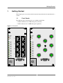
1.1
Front Panels
Two different types of front panels are available for the F302:
• 8 RJ45 connectors on a 12HP front panel (standard)
• 8 M12 connectors on a 16HP front panel (optional)
Figure 1. Front panels
PWR
RST
S1
S2
LNK1
ACT1
LNK2
ACT2
LNK3
ACT3
LNK4
ACT4
LNK5
ACT5
LNK6
ACT6
LNK7
ACT7
LNK8
ACT8
1
2
3
4
5
6
7
MEN
F302
8
SERVICE
MEN Mikro Elektronik GmbH
20F302-00 E4 – 2010-12-16
PWR
RST
S1
S2
LNK1
ACT1
LNK2
ACT2
LNK3
ACT3
LNK4
ACT4
LNK5
ACT5
LNK6
ACT6
LNK7
ACT7
LNK8
ACT8
MEN
F302
2
1
3
5
4
6
7
8
SERVICE
15
Getting Started
1.2
Integrating the Board into a System
You can use the following "check list" when installing the F302 in a CompactPCI
system for the first time.
Power-down the system.
Insert the F302 into a peripheral slot of your CompactPCI system, making sure
that the CompactPCI connectors are properly aligned.
Note: The peripheral slots of every CompactPCI system are marked by a circle
on the backplane and/or at the front panel.
Power-up the system.
You can now install driver software for the F302 Ethernet controllers, if needed.
1.3
Installing Driver Software
For a detailed description on how to install driver software please refer to the
respective documentation.
You can find any driver software available for download on the MEN website.
MEN Mikro Elektronik GmbH
20F302-00 E4 – 2010-12-16
16
Functional Description
2
Functional Description
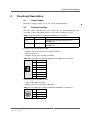
2.1
Power Supply
The F302 is supplied with +3.3V or +5V via the CompactPCI bus.
2.2
Ethernet Interface
The F302 offers eight Ethernet ports at the front. An additional Ethernet port
accessible via the CompactPCI interface can be made available on request.
Table 1. Signal mnemonics of Ethernet 10/100Base-T connectors
Signal
Direction
Function
RX+/-
in
Differential pair of receive data lines for
10/100Base-T
TX+/-
out
Differential pair of transmit data lines for
10/100Base-T
Connector types for the RJ45 version:
• Modular 8/8-pin mounting jack according to FCC68
• Mating connector:
Modular 8/8-pin plug according to FCC68
Table 2. Pin assignment of 8-pin RJ45 Ethernet 10/100Base-T connectors
1
RX+
2
RX-
3
TX+
4
-
5
-
6
TX-
7
-
8
-
1
8
Connector types for the M12 version:
• 4-pin circular M12 receptacle
• Mating connector: 4-pin circular M12 plug
Table 3. Pin assignment of 4-pin M12 Ethernet 10/100Base-T connectors
3
2
MEN Mikro Elektronik GmbH
20F302-00 E4 – 2010-12-16
1
TX+
2
RX+
3
TX-
4
RX-
4
1
17
Functional Description
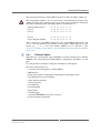
The management interface and the Ethernet ports have their own MAC address etc.
!
The unique MAC addresses are set at the factory and should not be changed. Any
attempt to change these addresses may create node or bus contention and thereby
render the switch inoperable. The MAC addresses on the F302 are:
•
•
•
•
•
•
Management interface:
Port 1:
Port 2:
...
Port 8:
Port 9 (Gigabit Uplink):
0x 00 C0 3A 9F xx x0
0x 00 C0 3A 9F xx x1
0x 00 C0 3A 9F xx x2
0x 00 C0 3A 9F xx x8
0x 00 C0 3A 9F xx x9
where "00 C0 3A" is the MEN vendor code, "9F" is the MEN product codes, and
"xx x" is the hexadecimal serial number of the product, which depends on your
switch, e.g., "... 02 A3" for serial number "000042" (0x2A) and port 3. (See
Chapter 3.2 Finding out the Board’s Article Number, Revision and Serial Number
on page 22.)
2.2.1
Ethernet Switch
The F302 uses a manageable 8-port 10/100Base-T switch component, the Marvell
88E6095. The switch provides 10/100 Mbits/s configuration possibility on each
port.
It is also possible to configure each port in half-duplex or full-duplex.
The device characteristics are:
•
•
•
•
•
•
•
•
•
•
•
•
8 external ports configurable as 10/100 Mbits/s
MII interface
Each external port is configurable in half-duplex or full-duplex mode
Non-blocking wire speed switching
Store-and-forward mode
Auto negotiation
Port mirroring
Port monitoring
Flow control
VLAN support
Automatic MDI/MDI-X crossover (all ports)
Port based frame priorization
MEN Mikro Elektronik GmbH
20F302-00 E4 – 2010-12-16
18
Functional Description
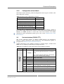
2.2.2
Configuration of the Switch
The F302 loads the following standard configuration for the 8 ports available at the
front of the unit at startup:
Table 4. Default switch configuration at startup
Setting
Default
Duplex mode
Full Duplex
Port speed
Auto-Negotiate
VLAN (port-based)
Off
QoS (Quality of Service)
Off
Port mirroring and port monitoring
Off
Port trunking
Off
All of the ports are individually configurable using an external dongle, a Telnet or
Secure Shell (SSH) command line interface via the D-Sub service connector or over
Ethernet via SNMP (Version 3) or the unit’s web server interface. For further
information about configuration options please refer to the documentation of the
F302 firmware.
Service Interface (RS232 / I2C)
2.3
The service connector features an RS232 UART interface for maintenance
purposes. Further information about maintenance and configuration options is
provided in the documentation of the F302 firmware.
An I2C connection is also available to connect an external dongle (available from
MEN) for easy dumping or uploading of configuration data.
Table 5. Pin assignment of the 9-pin D-Sub service interface connector
Pin
Name
Description
General purpose I/O 0
1
GPIO[0]
Apply active signal for more than 2 seconds:
Reset
Apply active signal for more than 10 seconds:
Reset with restored factory settings
1
5
MEN Mikro Elektronik GmbH
20F302-00 E4 – 2010-12-16
6
2
RS232_RX RS232 receive data
3
RS232_TX RS232 transmit data
9
4
SCL
I2C data clock for external dongle
5
GND
Ground
6
GPIO[1]
7
+3.3V
8
SDA
I2C serial data input/output for external dongle
9
GND
Ground
General purpose I/O 1
Used for detection of external dongle
Power supply for external dongle
19
Functional Description
2.4
Front Panel Status LEDs
The F302 has a number of status LEDs at its front panel.
Table 6. Front-panel status LEDs
LED
Description
PWR
General Power Good
RST
Reset
S1
Service LED 1
S2
Service LED 2
LNK 1
Port 1 link/data receive
ACT 1
Port 1 link/data receive
LNK 2
Port 2 link/data receive
ACT 2
Port 2 link/data receive
...
...
LNK 8
Port 8 link/data receive
ACT 8
Port 8 link/data receive
2.4.1
General Status LEDs
Table 7. General status LEDs
LED
Description
PWR
On: Switch is powered on
RST
On: Reset signal is active
2.4.2
Service LEDs
Table 8. Service LEDs
LED
Description
S1
Micro controller LED (function depends on software)
S2
Micro controller LED (function depends on software)
The micro controller uses the LEDs connected to it to indicate the reason for an
error during startup. The status LED will blink or light up as listed in Table 9, Error
codes signaled via service LEDs until the system is restarted or completely powered
off. The supported error codes are as follows:
MEN Mikro Elektronik GmbH
20F302-00 E4 – 2010-12-16
20
Functional Description
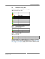
Table 9. Error codes signaled via service LEDs
Failure source
S1
S2
RS232 UART
fast
fast
Memory
fast
slow
Marvell switch access
slow
fast
Marvell switch internal PHYs
slow
on
External PHYs
slow
slow
Temperature sensor
on
fast
IDPROM
on
on
PoE
on
slow
Firmware image
off
on
Unspecified
off
fast
"Slow" means blinking with a frequency of 1 Hz, "fast" means blinking with a
frequency of 10 Hz.
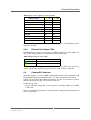
2.4.3
Ethernet Port Status LEDs
Each Ethernet user port (1 to 8) provides two LEDs to display its status (LNK x and
ACT x). The display LEDs act as described in the following table.
Table 10. Ethernet port status LEDs
LED
Description
LNK x
On: Link up
ACT x
On: Transmit or receive activity
An alternative LED configuration with one LED indicating link status and receive
activity and the other indicating transmit activity can be realized on demand.
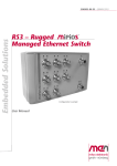
2.5
CompactPCI Interface
The F302 supports a 32-bit 33-MHz CompactPCI interface fully compatible with
CompactPCI specification PICMG 2.0 Rev. 3.0. The board works with 3.3V for
V(I/O) only. For full CompactPCI functionality only the J1 connector is needed,
therefore the board only has a J1 connector to the bus.
Connector type of J1:
• 110-pin shielded, 2mm-pitch, 5-row receptacle according to IEC 917 and IEC
1076-4-101
The pin assignment of connector J1 as defined in the CompactPCI specification will
not be repeated here.
MEN Mikro Elektronik GmbH
20F302-00 E4 – 2010-12-16
21
Appendix
3
Appendix
3.1
Literature and Web Resources
• F302 data sheet with up-to-date information and documentation:
http://www.men.de/products/02F302-.html
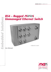
3.2
Finding out the Board’s Article Number, Revision and
Serial Number
MEN user documentation may describe several different models and/or hardware
revisions of the F302. You can find information on the article number, the board
revision and the serial number on two labels attached to the board.
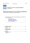
• Article number: Gives the board’s family and model. This is also MEN’s ordering number. To be complete it must have 9 characters.
• Revision number: Gives the hardware revision of the board.
• Serial number: Unique identification assigned during production.
If you need support, you should communicate these numbers to MEN.
Figure 2. Labels giving the board’s article number, revision and serial number
Complete article number
Article No.:
02F302-00
Serial No.:
000001
Rev. 00.00.00
Serial number
Revision number
MEN Mikro Elektronik GmbH
20F302-00 E4 – 2010-12-16
22