1
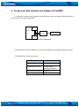
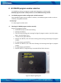
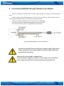
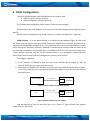
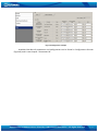
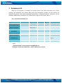
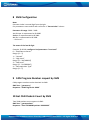
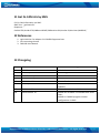
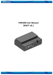
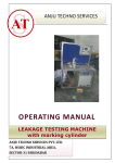
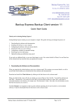
FM1100 with Light Vehicles Can adapter LV-CAN200 Manual V1.8 Reproduction forbidden without Teltonika, UAB written authorization – All Rights Reserved 1/12 TABLE OF CONTENTS 1 2 3 4 Legal Notice .................................................................................................................................. 3 Safety Introductions ..................................................................................................................... 3 Purpose of Light Vehicles Can Adapter LV-CAN200 ..................................................................... 4 LV-CAN200 program number selection ....................................................................................... 5 4.1 LV-CAN200 program number configuration via SMS command .......................................... 5 4.2 Selecting LV-CAN200 program number manually ................................................................ 5 5 Connecting FM1100 with Light Vehicles Can adapter ................................................................. 6 6 FM11 Configuration ..................................................................................................................... 7 7 Parameters ID ............................................................................................................................. 10 8 SMS Configuration...................................................................................................................... 11 9 CAN Program Number request by SMS ..................................................................................... 11 10 Get CAN Packets Count by SMS.............................................................................................. 11 11 Get LV-CAN info by SMS ......................................................................................................... 12 12 References .............................................................................................................................. 12 13 Changelog ............................................................................................................................... 12 Reproduction forbidden without Teltonika, UAB written authorization – All Rights Reserved 2/12 1 Legal Notice Copyright © 2012 Teltonika. All rights reserved. Reproduction, transfer, distribution or storage of part or all of the contents in this document in any form without the prior written permission of Teltonika is prohibited. Other products and company names mentioned here may be trademarks or trade names of their respective owners. The manufacturer reserves the right to make changes and/or improvements at any time in design, functionality, parameters and electrical characteristics without any prior notice and without incurring obligations. 2 Safety Introductions This chapter contains information on how to operate device safely. By following these requirements and recommendations, you will avoid dangerous situations. You must read these instructions carefully and follow them strictly before operating the device! The device uses a 10 V...30 V DC power supply. The nominal voltage is 12 V DC. The allowed range of voltage is 10 V...30 V DC. To avoid mechanical damage, it is advised to transport the device in an impact-proof package. Before usage, the device should be placed in position where all its LED indicators would be visible. LED indicators shows status of operation the device is in. When connecting the connection cables to the vehicle, the appropriate jumpers of the vehicle power supply should be disconnected. Before dismounting the device from the vehicle, the plug must be disconnected. The device is designed to be mounted in a zone of limited access, which is inaccessible for the operator. All related devices must meet the requirements of standard EN 60950-1. Teltonika is not responsible for vehicle damage caused by installation of adapter. Reproduction forbidden without Teltonika, UAB written authorization – All Rights Reserved 3/12 3 Purpose of Light Vehicles Can Adapter LV-CAN200 LV-CAN200 is used to listening data from light vehicles. With this adapter FM1100 device is able to collect and send vehicle data. ECU1 CAR CAN L H LVCAN200 FM1100 ECU2 Figure 1 Connection block diagram FM1100 shares the same USB port for connecting adapter and configuring device with PC. LV-CAN200 Technical characteristics: PARAMETER VALUE Supply voltage 10 to 30V Power supply current Average 10mA Max (peak) 100mA -40..85 ºC 60 % (non condensate) Working temperature Max working humidity Reproduction forbidden without Teltonika, UAB written authorization – All Rights Reserved 4/12 4 LV-CAN200 program number selection LV-CAN200 must be set to program number which depends on vehicle model. Needed program number is always written on LV-CAN200 mounting scheme. 4.1 LV-CAN200 program number configuration via SMS command Since FM1100 firmware version 43.00.17 and later, LV-CAN200 program number can be set remotely, using SMS command: setcanprog X X is new program number value. 4.2 Selecting LV-CAN200 program number manually Steps to set program number: Hold SWITCH down till LED stars blinking Release the SWITCH Then LED starts blinking and counting first digit of program number, (one blink means digit 1, two blink digit 2 etc.) To stop counter push SWITCH Release the SWITCH, then LED starts blinking and counting second digit of program number To stop counter push SWITCH Release the SWITCH, then LED starts blinking and counting third digit on program number To stop counter push SWITCH Release SWITCH, if programming is succeded LED will blink 10 times Figure 2 Adapter signaling led Reproduction forbidden without Teltonika, UAB written authorization – All Rights Reserved 5/12 5 Connecting FM1100 with Light Vehicles Can adapter Connect USB Plug to FM1100 device, connect Light Vehicles Can adapter to other end of the cable. Connect Light Vehicles Can adapter Pin 1 and Pin 2 to cars CAN bus. CAN interface location of the supported light vehicle is described on mounting scheme. Connect car power supply lines to Pin 3 positive, Pin 4 Negative. Pins 9,10 connection is optional it depends on exact car model. For exact pinout see sticker on Light Vehicles Can adapter. Figure 3. LV-CAN200 Adapter connection cable pinout Attention! For detailed connection diagram of adapter to light vehicle please contact Teltonika, LTD sales representative and provide CAR manufacturer, model and year information. Attention! Do not swap CAN L and CAN H lines. Do not swap power supply lines. Make sure that voltage do not exceeds 30V. Power supply lines should be connected at the end of installation work. Reproduction forbidden without Teltonika, UAB written authorization – All Rights Reserved 6/12 6 FM11 Configuration To use LV-CAN200 adapter with FM1100 device you need to have: a. FM11 firmware number 43.XX.XX b. FM11 configurator version 1.43.XX.XX For firmware and configurator please contact Teltonika sales manager. FM1100 shares the same USB port for connecting LV-CAN200 adapter and configuring device with PC. FM1100 can be configured using “SCAN” function or “Offline Configuration” (Figure 8) SCAN function – is in use when FM1100 is connected to CAN adapter (Figure 6), then wait 10s (Note, that car engine must be started), disconnect adapter from FM1100, and connect PC USB cable to FM1100 Device (Figure 3). It is very important not to disconnect FM1100 from power source during this operation, because if FM1100 is reconnected all received CAN bus data will be lost. FM1100 remembers received data from LV-CAN200 and at the end of the procedure when “SCAN” button is pressed, user will see all CAN data which is sent by adapter. Enable CAN data which needs send to server and save configuration pressing “Save” button. To configure CAN data: 1. In car, connect LV-CAN200 to CAN bus and to the FM1100 device (Figure 6), wait 10 seconds. Note, that car engine must be started. 2. Disconnect LV-CAN200 from FM1100, and connect PC USB cable to FM1100 Device (Figure 7). It is very important not to disconnect FM1100 from power source, because then all CAN data will be lost. LV-CAN200 Connection cable USB FM1100 LV-CAN100 to FM1100 Figure 4 Connect adapter USB Cable PC USB FM1100 Figure 5 Connect FM1100 to PC and configure CAN bus data which can be read from your car is shown in “Light Vehicles Can adapter supported cars” document. Reproduction forbidden without Teltonika, UAB written authorization – All Rights Reserved 7/12 Offline configuration – user can select which CAN data can be read from LV-CAN200 need to be sent to server without connection to adapter. Please note that parameters depend on vehicle manufacturer and vehicle model. Please for further information check “Light Vehicles Can adapter supported cars” document. There are two types of operations with CAN data elements: Monitoring of CAN bus data CAN bus data event capturing Monitoring method is used when user wants to receive CAN data on regular basis, for example every 20 seconds. Event functionality is used to store additional AVL packet when state of CAN element is changing. For example Speed changes, low fuel level, engine temperate, etc. Send data to server field – allows enabling CAN element so it is added to the AVL data packet and sent to the server. By default, all CAN elements are disabled and FM1100 records only GPS data. It is possible to set CAN message priority: On Low Priority, On High Priority, and On Panic. Regular packets are sent as Low priority records. When low priority event is triggered, FM1100 makes additional record with indication what was the reason for that was CAN element change. When High priority is selected, module makes additional record with high priority flag and sends event packet immediately to the server by GPRS. Panic priority triggers same actions as high priority, but if GPRS fails, it sends AVL packet to server using SMS mode if SMS is enabled in SMS settings. Data Acquisition Type – defines when to generate event – when value enters defined range, exits it or both, also is possible to select event which you want to generate then you change values, like crossing both values in high and low levels (Hysteresis). High and Low levels – defines CAN value range. If CAN value enter or exits this range, FM1100 generates event by “Data Acquisition Type” settings. Figure 6 show example of FM1100 CAN configuration. Reproduction forbidden without Teltonika, UAB written authorization – All Rights Reserved 8/12 Figure 6 Configurator example Available CAN Bus IO parameters and configuration can be found in Configurators CAN tab (Figure 8) and in next chapter “Parameters ID”. Reproduction forbidden without Teltonika, UAB written authorization – All Rights Reserved 9/12 7 Parameters ID When no I/O element is enabled, AVL packet comes with GPS information only. After enabling I/O element(s) AVL packet along with GPS information contains current value(s) of enabled I/O element. AVL packet decoding is described in “FMXXXX Protocols” document. List of available CAN bus data, parameter size, ID and value range you can find in table 1. Table 1 ACQUIRED PARAMETRS IO ID Category name Param index (signal) name Size (Bytes) Param IO ID Value range 65265 – Cruise Control/Vehicle Speed 61443 – Electronic Engine Controller #2 0 Vehicle Speed 1 81 0-250 km/h* 1 Accelerator Pedal Position 4 82 0-100 %* 65257 – Fuel Consumption 65276 – Dash Display 2 Total Fuel Used 4 83 0-99999999liters* 3 Fuel Level [liters] 4 84 0-100 liters* 61444 – Electronic Engine Controller #1 65217 – High Resolution Vehicle Distance 4 Engine RPM 4 85 0-8200 rpm* 5 Vehicle Distance 4 87 0-2145000000 meters* 65276 – Dash Display 6 Fuel Level [%] 4 89 0-100 %* NOTE: „Total Fuel Used“ is sent to server multiplied by 10. Example: if value was 150.5 liters, „1505“ will be sent to server. Reproduction forbidden without Teltonika, UAB written authorization – All Rights Reserved 10/12 8 SMS Configuration Note: Prameter index is second digit from the right. For parameters name and ID refer to Picture 1 “Param Index“ column. Prameters ID range: 2000 – 2060. 1st CAN per is represented as ID 2000 2nd per is represesented as ID 2010 3rd per is represented as ID 2020 … And so on…. The mean of the last ID digit: Example: ID 2013 – configures 2nd parameters “Low Level” 0 – “Send Data to Server” Range: [0 – 3] 1 – “Unused” 2 – “High Level” Range: [0 – 2147483647] 3 – “Low Level” Range: [0 - -2147483647] 4 – “Data aquisition Type” Range: [0 – 5] 9 CAN Program Number request by SMS CAN program number can be obtained via SMS: SMS Text: “ getcanprog” Response: “CAN Program Nr: XXXX” 10 Get CAN Packets Count by SMS Total CAN packets count request via SMS: SMS Text: “ getcanpackets” Response: “Total LVCAN200 packets: XXXXXXXX” Reproduction forbidden without Teltonika, UAB written authorization – All Rights Reserved 11/12 11 Get LV-CAN info by SMS Full LV-CAN information via SMS: SMS Text: “ getlvcaninfo” Response: “ Per0Nr:276;Per1Nr:276;SWDate:130405;SWRevision:91;KernVer:21;KernVar:0;MdlID:0;” 12 References 1. Light Vehicles Can adapter LV-CAN200 Supported cars 2. Cars mounting scheme 3. FM1100 User Manual 13 Changelog Version 0.1 1.2 1.3 1.4 1.5 1.6 Date 2012 December 14 2013 September 4 2014 February 4 2014 February 18 2014 March 7 2014 April 8 1.7 1.8 2014 June 20 2014 October 14 Changes Initial release SMS configuration added Add LV-CAN info SMS Picture fixed Picture fixed Table 2 ACQUIRED PARAMETRS IO ID updated Table 1 Param Index added Added new available LV-CAN200 cable wires color; Added LV-CAN200 program number configuration via SMS Reproduction forbidden without Teltonika, UAB written authorization – All Rights Reserved 12/12