1
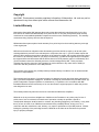
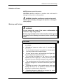
HR2
Ultrasonic Motor
User Manual
D/N: MSP2458000-00 REV: B
Nanomotion Ltd. POB 623, Yokneam 20692, Israel
Tel: 972-73-2498000 Fax: 972-73-2498099
Web Site: www.nanomotion.com
E-mail: [email protected]
September 2008
Copyrught and Limited Warranty
Copyright
April 2000. This document contains proprietary information of Nanomotion, Ltd. and may not be
reproduced in any form without prior written consent from Nanomotion Ltd.
Limited Warranty
Nanomotion (hereinafter NM) warrants the product (other than software) manufactured by it to be free
from defects in material and workmanship for a period of time of one year (except those parts normally
considered as consumable/expendable components such as motor conditioning brushes). The warranty
commences thirty (30) days from the date of shipment.
NM warrants those parts replaced under warranty for a period equal to the remaining warranty coverage
of the original part.
NM’s sole and exclusive obligation under this warranty provision shall be to repair, or at its sole option
exchange defective products or the relevant part or component, but only if : (i) the Purchaser reports the
defect to NM in writing and provides a description of the defective product and complete information about
the manner of its discovery within ten (10) days of its discovery; (ii) NM has the opportunity to investigate
the reported defect and determines that the defect arises from faulty material, parts or workmanship; and
(iii) the Purchaser returns the affected product to a location designated by NM. These provisions
constitute the exclusive remedy of the Purchaser for product defects or any other claim of liability in
connection with the purchase or use of NM products.
This warranty policy applies only to NM products purchased directly from NM or from an authorized NM
distributor or representative.
This warranty shall not apply to (i) products repaired or altered by anyone other than those authorized by
NM; (ii) products subjected to negligence, accidents or damage by circumstances beyond NM control; (iii)
product subjected to improper operation or maintenance (i.e. operation not in accordance with NM
Installation Manuals and/or instructions) or for use other than the original purpose for which the product
was designed to be used.
The warranty stands only when the motors are used with the NM drivers/ amplifiers.
NM shall not in any event have obligations or liabilities to the Purchaser or any other party for loss of
profits, loss of use or incidental, increased cost of operation or delays in operation, special or
consequential damages, whether based on contract, tort (including negligence), strict liability, or any other
theory or form of action, even if NM has been advised of the possibility thereof, arising out of or in
connection with the manufacture, sale, delivery, use, repair or performance of the NM products. Without
limiting the generality of the preceding sentence, NM shall not be liable to the Purchaser for personal
injury or property damages.
Nanomotion Ltd.
Page 2 of 30
CE Compliance
CE Compliance
The motors and drivers comply to the following directive:
Safety : IEC 61010-1:1990
EMC
: 89/336/EEC as amended by 92/31/EEC and 93/68/EEC
Harmonized Standards to which conformity is declared:
EN 50081- 2:1993/EN 55011:1991
Generic Emission Standards Class A for radiated emission and
Class B for conducted emission.
EN 50082- 2:1995 Generic Immunity Standard
NOTE: UHV motors are designed for convenient interface to the
UHV setup. The motors are therefore supplied with three open
electrical leads. Whereas standard motors comply with CE
regulations and the UHV motors have the same internal design as
standard motors, the UHV motors are supplied as components and
CE conformity in both EMI and Safety must be implemented as part
of the UHV system design.
Nanomotion Ltd.
Page 3 of 30
Definition of Terms and Warnings
Preface
This Installation Manual is designed to help the reader install and
operate the various types of Nanomotion’s HR2 piezoceramic
Motors. This manual assumes that the reader has a fundamental
understanding of basic servo systems, as well as motion control
concepts and applicable safety procedures.
The manual describes the physical dimensions as well as the
mechanical and electrical installation procedures for these motors.
Warranty
The motors are covered by warranty for a period of twelve months
from the date of invoice.
The following voids the warranty:
Misuse or incorrect mounting, incorrect electrical connections,
removal of motor cover or of serial number, modification of parts,
and any other use that is not according to the cautions and
warnings provided in this guide.
Liability for replacement will be determined after inspection of any
defective item by Nanomotion or an approved agent.
Nanomotion Ltd.
Page 4 of 30
Definition of Terms and Warnings
Definition of Terms
NOTE: Additonal usefull information.
CAUTION: Identifies conditions or practices that could result in
damage to this product or other property.
WARNING: Identifies conditions or practices that could
result in personal injury, damage to the product or damage to
other property.
Warnings and Cautions
WARNINGS
Do not remove the cover of the motor or disassemble its
connector. High voltage inside.
Be sure to ground the motor to the electrical network ground
(according to the following instructions) before operating the
motor.
CAUTIONS
§
Arrows on motor indicate direction of motion. Align
accordingly.
§
Do not set power-on unless motor is mounted and
preloaded!
Do not immerse the motor in any liquid or cleaning agent.
§
§
§
Nanomotion Ltd.
Use only a clean cloth to wipe the motor.
Be sure that the motor, and specifically the 'finger tips',
are not subjected to mechanical shocks.
§
Be sure that the distance of the motor to the plate
enables the motor finger tip to contact the driving plate,
otherwise the motor might be damaged during operation.
§
The mounting base and the method used for mounting
should be designed for maximum mechanical rigidity and
stiffness.
§
Reducing the length of the supplied motor cable may
damage the motor. Do not attempt to shorten the cable
without prior confirmation by Nanomotion.
§
Extending the motor cable will not damage the motor,
however it will affect its performance.
Page 5 of 30
Table of Contents
Table of Contents
1.
2.
INTRODUCTION............................................................................................................7
1.1
About the Motor ..............................................................................................7
1.2
Vacuum Motors...............................................................................................7
1.3
HR2 System Parts...........................................................................................8
1.4
Handling ..........................................................................................................8
1.5
Installation and Servicing...............................................................................8
PREPARATION AND INSTALLATION..........................................................................9
2.1
Preparation......................................................................................................9
2.1.1
Mounting Base................................................................................................10
2.1.2
Limiting Stage Motion .....................................................................................11
2.2
Motor Installation..........................................................................................11
2.2.1
Bonding the Driving Plate to the Stage ...........................................................12
2.2.2
Mounting the Motor.........................................................................................15
2.2.3
Motor Grounding.............................................................................................17
2.2.4
Motor Connections..........................................................................................17
2.2.4.1 Motor Connector Pinout ..................................................................................18
2.2.4.2 System Electrical Configuration ......................................................................19
2.2.5
3.
Motor Run-In...................................................................................................19
SPECIFICATIONS .......................................................................................................20
3.1
General ..........................................................................................................20
3.2
Specification Parameters .............................................................................22
3.2.1
Performance ...................................................................................................22
3.2.2
Electrical .........................................................................................................22
3.2.3
Environmental.................................................................................................22
3.2.4
Physical Dimensions.......................................................................................22
3.2.5
Performance Envelope with the AB5 driver.....................................................23
3.2.6
Performance Envelope with AB1A, AB2, AB4.................................................25
3.3
Schematics....................................................................................................28
3.3.1
Dimensions for Standard and High-Vacuum Motors .......................................28
3.3.2
Dimensions for Ultra-High-Vacuum Motors ....................................................29
3.3.3
Mounting Base Dimensions ............................................................................30
Nanomotion Ltd.
Page 6 of 30
Introduction
1.
Introduction
1.1
About the Motor
The HR2 motors are high precision ceramic motors. Designed and
manufactured by Nanomotion, Ltd., the HR2 motors combine
unlimited stroke with high resolution in compact dimensions.
Among its applications are microscopy, precision motion, robotics,
etc.
The motors provide a linear response to the input voltage. The
operation of the motor and driver resembles that of a DC-motor
driven by a voltage amplifier.
The specifications described in this chapter apply only to the motor
driven by AB1A Driver. Minor differences may result if AB2, AB4 or
AB5 are used.
1.2
Vacuum Motors
Applications of the Nanomotion motors for vacuum and highvacuum environments include wafer inspection metrology,
scanning stages and lithography. The HR2-V and HR2-U motors
are constructed of materials that have been selected and designed
for high vacuum compatibility.
Nanomotion Ltd.
Page 7 of 30
Introduction
1.3
HR2 System Parts
A complete set for a single axis will comprise of the following:
a) HR2 Motor
b) 1.8mm spacer
c) Ceramic Driving Plate for
linear applications or Ceramic
Driving Ring/Disk for rotary
applications.
(see
section
2.2.1)
d) One of the following drivers:
§
AB1A
§
AB2
§
AB4
§
AB5
NOTE: For the first 4 driver options, use a standard off-the-shelf
DC Controller with a servo rate of 10KHz or higher. You may
consult Nanomotion for the recommended controller. The option for
NCD Driver Controller Box consists of a driver and an integrated
controller.
1.4
Handling
CAUTIONS
Do not set power-on unless the motor is mounted and preloaded!
Do not immerse the motor in any liquid or cleaning agent.
Use only a clean cloth to wipe the motor.
Be sure that the motor, and specifically the 'finger tips', are not
subjected to mechanical shocks.
1.5
Installation and Servicing
It is recommended to follow the installation instructions in this
guide, when mounting and installing the motor. The HR2 does not
contain any user-serviceable parts.
Nanomotion Ltd.
Page 8 of 30
Preparation and Installation
2.
Preparation and Installation
2.1
Preparation
For optimal motor performance, it is recommended to use the
Ceramic driving plates provided by Nanomotion. These driving
plates have been specifically designed to work with Nanomotion
motors.
Substituting this plate with any other material might reduce motor
performance or damage the motor.
NOTE: The instructions given in this section refer to the standard
ceramic driving plates provided by Nanomotion. Nanomotion can
not guarantee performance attained by plates purchased from
other sources.
Nanomotion Ltd.
Page 9 of 30
Preparation and Installation
2.1.1
Mounting Base
Prepare a base with four oval holes as described in Section 3.2.8 Mounting Base Dimensions. The base should be positioned
perpendicular to the Ceramic driving plate that is bonded to the
stage.
If necessary, refer to the schematic for motor dimensions.
CAUTION: The mounting base and the method used for mounting
should be designed for maximum mechanical rigidity and stiffness.
Stage Carriage
Ceramic Driving
Plate location
Stage Base
Mounting
Base
4x oval
holes
Figure 1: Motor Mounting Base
The mounting base dimensions diagram refers to the front surface
of the Ceramic driving plate.
For driving plate dimensions please refer to the price list.
The four screws securing the motor to the mounting surface will be
inserted from its underside. Any protrusion of the screws might
interfere with motion on another axis.
Nanomotion Ltd.
Page 10 of 30
Preparation and Installation
2.1.2
Limiting Stage Motion
The provided ceramic driving plate should not exceed the stage. It
must be supported by a solid even backing along all its length, in
order to avoid breaking when motor is pressed against it.
The Ceramic driving plate should also be at least 10 mm longer
than the stage travel length, otherwise the motor finger tips might
be damaged.
If the above requirements are not met, limit the stage travel
distance using end stops.
2.2
Motor Installation
The installation procedure consists of the following:
Nanomotion Ltd.
§
Bonding the Ceramic Driving plate to the stage
§
Mounting the motor
§
Grounding the motor
§
Connecting the motor to its driver
Page 11 of 30
Preparation and Installation
2.2.1
Bonding the Driving Plate to the Stage
The Driving Ceramic Plate interfaces between the motor 'finger tips'
and the stage, and provides the required friction.
Bond the driving plate provided by Nanomotion to the stage surface
interfacing with the motor 'finger tips', according to the instructions
given in this section.
S tag e
A lu m in a D riv in g P la te
Figure 2: Bonding the Ceramic Driving Plate
Nanomotion Ltd.
Page 12 of 30
Preparation and Installation
1. Clean the bonding region on the stage, using a suitable agent
such as Acetone or Methanol.
2. Peel off the self-adhesive backing paper on the Ceramic driving
plate. The self adhesive tape is compatible with high-vacuum
applications.
3. Referring to the figure below, place the plate in position,
verifying that:
§ There is a maximum of 2.0mm between the lower edge of the
Ceramic driving plate and the motor mounting surface.
§ There is a minimum of 11.0mm between the upper edge of
the Ceramic driving plate and the motor mounting surface.
Alumina driving plate
Mounting Surface
11 mm (min)
2.0 mm (max)
Figure 3: Ceramic Driving Plate Position
Continued on the following page….
Nanomotion Ltd.
Page 13 of 30
Preparation and Installation
4. Referring to the figure below, apply two drops of epoxy
adhesive, on the center of the Ceramic driving plate upper
surface, about 2cm apart. The Epoxy must bond between the
plate and the stage.
Recommended adhesive:
§
Emerson & Cuming ecobond 24, for vacuum applications
§
3M 2216 epoxy or CIBA GEIGEY Arldite Radite, for nonvacuum applications
NOTE: Be sure the epoxy contacts the upper surfaces of the plate
and the stage carriage but does not flow over the Ceramic plate
front surface.
Stage
2 cm
Epoxy
Alumina Plate
Figure 4: Securing the Ceramic Driving Plate to the Stage
5. Allow the required time period for curing, according to the Epoxy
manufacturer specifications.
6. Mount the motor according to the following section.
Nanomotion Ltd.
Page 14 of 30
Preparation and Installation
2.2.2
Mounting the Motor
After bonding the Ceramic driving plate to the stage, loosely mount
the motor so it faces the Ceramic driving plate according to the
instructions in this section.
NOTE: The motor does not have an 'up' or 'down' side and may be
mounted on either surface so that the cable protrudes from either
the left or the right side.
Stage
Mounting Base
Spacer
Allen key
M3 socket
head screws
For M3
Motor
Figure 5: Accessories for mounting
1. Align the motor to the four holes on the motor mounting
surface.
2. Secure the motor to the surface using four M3 screws and
spring washers inserted from the underside of the mounting
surface. Do not tighten yet.
3. Adjust the distance between the motor and the Ceramic driving
plate as follows:
§ Place the 1.8 mm spacer between the motor surface that
faces the Ceramic driving plate, and the Ceramic driving
plate.
§ Gently press the motor against the Ceramic plate to the
thickness of the spacer.
§ Lightly screw the four motor screws and then remove the
spacer.
§
Fully tighten the motor screws at a torque of 0.5 to 0.7Nm.
4. Ground the motor according to the following section.
Nanomotion Ltd.
Page 15 of 30
Preparation and Installation
Insert M3
screws. Do not
tighten yet
Figure 6: Inseting screws
Insert spacer between motor and
ceramic drive strip.
Press the motor against the spacer
and tighten the screws.
Pull spacer out.
Figure 7: Spacing and tightening
Nanomotion Ltd.
Page 16 of 30
Preparation and Installation
2.2.3
Motor Grounding
Warning !!!
Be sure to ground the motor to the electrical network ground
(according to the following instructions) before operating the
motor.
1. Prepare a grounding wire and a terminal connection with the
following specifications:
§ Terminal diameter - for an M3 screw
§ Wire diameter
- minimum 18 AWG
§ Wire length - maximum of 2 meter
2. Open the motor ground screw (figures 15 & 16) and connect the
ground connection prepared in step-1.
3. Secure the terminal between the two lock washers.
4. Connect the other end of this cable to the electrical network
ground.
5. Connect the motor to its driver according to the instructions
given in the following section.
2.2.4
Motor Connections
This section describes the motor connector pinout and the
connections to each of the available drivers.
Make sure the driver is set to operate with the HR2 motor series.
CAUTIONS:
Reducing the length of the supplied motor cable may damage the
motor. Do not attempt to shorten the cable without prior
confirmation by Nanomotion.
Extending the motor cable will not damage the motor, however it
will affect its performance.
Nanomotion Ltd.
Page 17 of 30
Preparation and Installation
2.2.4.1
Motor Connector Pinout
WARNING: Do not remove the cover of the motor or
disassemble its connector. High voltage inside.
CAUTION: Do not set power-on unless the motor is mounted and
preloaded.
The motor driver connection is a standard 9 contacts D-type female
connector whose pinout is given below.
Connector
Motor
Red
Direction 1
Common
Direction 2
Screen
Black
White
Shield
Pinout
5
9
4
8
3
7
2
6
1
Figure 8: Motor Connector
NOTE: Pins 6 and 1 on the motor connector are shorted . This is
done for safety reasons – driver voltage is disabled unless pins 1 &
6 are shorted when motor is connected.
For Ultra High Vacuum motor:
The HR2 –2-U motor does not have an outlet cable or a connector.
Instead, there are 3 TFE jacketed wires extending outside the
motor: 1 black wire, 1 red and 1 white wire. The red and white
wires are directions 1 and 2 respectively, and the black wire is the
common. Also, the safety shorting between pins1 and 6 is not
implemented and should be preformed by the user.
WARNING
Since there is no cable shielding the HR2-2-U motor case to
the ground, it must be grounded by means of connection to
the network ground. Please refer to section 2.2.3 in the manual
for detailed instructions.
Nanomotion Ltd.
Page 18 of 30
Preparation and Installation
2.2.4.2
System Electrical Configuration
The Motor is to be operated by one of Nanomotion’s drivers.
Following is the two possible configurations:
Nanomotion’s Driver
Without an Integrated
LC circuit
LC
Box
Motor
Figure 9: Connection to a driver using an external LC box
Nanomotion’s Driver
With an Integrated Internal
LC circuit
Motor
Figure 10: Connection to a Driver with internal LC circuit
2.2.5
Motor Run-In
Run-in of the motor is important to reduce wear rate of the system
and to increase its lifetime.
The required run-in conditions are as follows:
§ velocity - 100 mm/sec.
§ Duty cycle - 50%.
§ Duration - 4 hours.
When the run–in is completed, carefully clean the ceramic strip with
a Q-Tip soaked with IPA, without dismounting the motor.
General remarks:
1. The procedure should be repeated if the motor is disconnected
and then reinstalled.
2. Do not perform run-in in a vacuum environment.
Nanomotion Ltd.
Page 19 of 30
Specifications
3.
Specifications
3.1
General
These specifications apply to the standard motor driven by the
AB1A Driver Box. The motor features a linear voltage response.
The motor and driver can be modeled as a DC-motor with friction
driven by a voltage amplifier, as illustrated in the following diagram.
.
Offset
Vin
+
+
Kf
-
1/M
1/S
Vel
Kfv
Figure 11: Block Diagram of the Motor and Driver
Where:
Nanomotion Ltd.
Vin
- Command to the driver -10 to +10 [V]
Kf
- Force constant [N/V]
Offset
- Starting voltage [V]
Kfv
- Velocity damping factor (similar to back EMF) [N x sec / m]
Vel
- Motor velocity [m/Sec]
M
- Moving mass [kg]
S
- Laplace variable [1/sec]
Page 20 of 30
Specifications
A block diagram of a typical HR2 Driver/Motor Sub-system is
shown below.
A command voltage of ±10V is applied to the driver. The driver
then generates a 39.6Khz sine wave (V motor) whose amplitude is
a function of command voltage. The sine wave drives the HR2
motor.
V Command
Driver
V Motor
Velocity, Force
HR2 Motor
Figure 12: Block Diagram of a typical HR2 Driver/Motor Sub-system
Nanomotion Ltd.
Page 21 of 30
Specifications
3.2
3.2.1
Specification Parameters
Performance
Maximum Allowable Velocity:
250 [mm/sec]
Dynamic Stall Force:
7 to 9 [N]
Static Holding Force
7 [N] (reference value)
Non-Energized Stiffness
1.4 to 1.8 [N/m]
Nominal Preload on Stage
36 [N]
Kf
1 to 2 [N/Volt command] – driver & command dependant
Kfv
24 to 36 [N · sec/m]
Offset
1 to 2 [V] – Driver dependant
Attainable Resolution
Better than 100 nm – see application notes.
Nominal Lifetime
20,000 hours under nominal operating conditions
3.2.2
Electrical
Maximal Voltage:
280Vrms, 39.6KHz, sine wave
Maximal Current consumption :
250 mA rms
Maximal Power Consumption :
10W
3.2.3
Environmental
Ambient Temperature:
0 - 50°C
Storage:
-40°C - +70°C
Humidity:
0 - 80% non condensing
Vacuum level (high-vacuum motors):
10
Vacuum level (ultra-high-vacuum motors):
Maximum Baking Temperature (for vacuum
motors):
3.2.4
-7
Torr (guaranteed only after baking)
-10
10
Torr (guaranteed only after baking)
120ºC (140ºC for ultra high vacuum motor)
Physical Dimensions
Length:
40.5mm
Width:
25.7mm
Height:
12.7mm
Weight:
40/60gr. (high & ultra high vacuum motors
/standard motor).
Nanomotion Ltd.
Page 22 of 30
Specifications
3.2.5
Performance Envelope with the AB5 driver
Due to the AB5’s unique features, the EOP of the motor, when being driven by it, is significantly
different than with all other Nanomotion drivers.
In order to avoid damaging the motor, it is important to adhere to the EOP as depicted in the
following graph and table.
Force vs. Velocity at varying working regimes
8
h
6
Force
g
4
f
e
d
2
a
0
0
c
b
100
200
300
Velocity [mm/sec]
Nanomotion Ltd.
Page 23 of 30
Specifications
Max Continuous
Duty Cycle [%]
Ambient
25°C
Ambient
25°C
Break Off
Break On
a
100
100
b
100
c
Operation time [sec]
Vacuum
Ambient 25°C
Vacuum
56
unlimited
500
100
54
unlimited
450
100
100
45
unlimited
280
d
100
100
33
unlimited
170
e
99
99
23
unlimited
100
f
53
58
15
170
66
g
33
48
11
77
44
h
17
28
6.5
32
25
Curve
Break On
Figure 13: EOP with AB5
As described in the AB5’s manual, when operating it in the Brake Off mode, the motor consumes
power at all times, even when the control command voltage is zero, thereby reducing the
thermal EOP.
If Break Off mode is desired while working in vacuum, the following operating regime must be
maintained: within the specific duty cycle stated in the chart, once the “maximal continuous
operation time” has elapsed, the motor must be disabled and allowed to cool off for at least 400
seconds.
For example, looking at curve C, in vacuum, with the break off: after 280 seconds of working at
the 45% duty cycle specified, the motor must be disabled for at least 400 seconds to cool off.
This is true also if a smaller duty cycle is maintained.
Nanomotion Ltd.
Page 24 of 30
Specifications
3.2.6 Performance Envelope with AB1A, AB2, AB4
The following graph illustrates motor velocity as a function of the applied driver command
voltage. Allowing up to 30 mm/sec variations, use it as a reference and as a guideline for
expected motor performance,
Motors velocity VS command .
Velocity [mm/sec]
300.0
250.0
200.0
150.0
100.0
50.0
0.0
0
1
2
3
4
5
6
7
8
9
10
Command [V]
.
Figure 14: Motor Velocity vs. Command 1
1
The motor operates horizontally at room temperature and low duty cycle (< 10%). It interfaces a Ceramic
Strip (according to Nanomotion Specifications) and a cross-roller high quality slide.
Nanomotion Ltd.
Page 25 of 30
Specifications
The following graph and table are designed to help the user determine the correct performance
envelope of operation so as to not overheat and damage the motor.
Force Vs. Velocity at various work regimes
Force [N]
8
g
f
6
4
b
2
d
c
e
a
0
0
100
200
300
Velocity [mm/sec]
25
Curve
a
b
c
d
e
f
g
Duty Cycle
100%
100%
100%
100%
78%
56%
50%
0
C
50
max.continuous
operation time Duty Cycle
100%
100%
92%
62%
87 seconds
47%
62 seconds
33%
56 seconds
30%
0
C
Vacuum
max.continuous
max.continuous
operation time Duty Cycle
operation time
100%
44%
184
137
26%
107
93
17%
72
70
13%
55
50
9%
39
45
8%
35
Figure 15: Performance envelope at various work regimes
Nanomotion Ltd.
Page 26 of 30
Specifications
How to define a performance envelope
An example for using the above graph and table:
A vacuum application requires 4N at a velocity of 20mm/sec. The graph shows that this point of
operation corresponds to curve “c”.
The table shows that curve “c” and a vacuum environment require that a duty cycle of 26% will
not be exeeded while maintaining a maximum continuous operation time of 107 seconds.
Vacuum application note – Heat dissipation mechanism is by radiation to the motor case and
by conduction through the fingers. Hence, the motor and the ceramic drive strip bases, must
both be thermaly designed to dissipate 0.5W each (per motor), with a temperature rise of 15°C
maximum. Also, the temperature of all parts in contact with the motor and with the ceramic drive
strip, should not exeed 40°C.
Nanomotion Ltd.
Page 27 of 30
Specifications
3.3
Schematics
3.3.1
Dimensions for Standard and High-Vacuum Motors
FINGER
TIPS
3.05
0.3 +0.1
3 ±0.2
7.5 ±0.2
15.6 ±0.2
12.7 -0.1
6
4.7
9.7 ±0.2
DIRECTION
OF MOTION
15.5 +0.5
25.7 -0.4
(
POWER
CABLE
3
2 FOR HR2-1-V)
GND PAN SCREW
M 3x0.5
41.7 REF (FREE)
40.5 REF
(PRELOADED)
38.7 ±0.2
M3x0.5
4 THREADS
FOR MOUNTING
NOTES:
1. ALL DIMENSIONS ARE IN MM
2. GENERAL TOLERANCE 0.1
5 NOM
TYPx2
11.2 ±0.2
2
21.5
TYPx2
1.8 0.05
(PRELOADED)
3 (FREE)
9.5 REF
(PRELOADED)
25
TYPx2
(c opy of layout drawing # MSP2-M30-L00-20)
10.7 REF (FREE)
Figure 16: Dimensions for Standard and High-Vacuum Motors
Nanomotion Ltd.
Page 28 of 30
Specifications
3.3.2
Dimensions for Ultra-High-Vacuum Motors
FINGER
3.05
TIPS
DIRECTION
OF MOTION
GND PAN SCREW
M3x0.5
41.7 REF (FREE)
6 ±0.2
3 ±0.2
12.7 -0.1
4 ±0.2
7.5 ±0.2
A
25.5 -0.2
5 NOM
40.5 REF (PRELOADED)
2
TYPx2
M3x0.5
4 THREADS
FOR MOUNTING
21.5
TYPx2
11.2 ±0.2
3 (FREE)
1.8 0.05
(PRELOADED)
2
21.5
M2x0.4
2 THREADS
FOR TERMINAL
BLOCK MOUNTING
7
TYPx2
VIEW A
38.7 -0.2
NOTES:
1. ALL DIMENSIONS ARE IN MM
2. GENERAL TOLERANCE 0.1
25
TYPx2
10.7 REF (FREE)
9.5 REF
(PRELOADED)
(c opy of layout drawing # SP2U-M10-L00-20)
Figure 17: Dimensions for Ultra-High-Vacuum Motors
Nanomotion Ltd.
Page 29 of 30
Specifications
3.3.3
Mounting Base Dimensions
Figure 18: Base Layout
Nanomotion Ltd.
Page 30 of 30