1
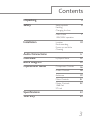
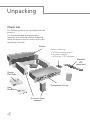
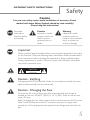
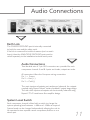
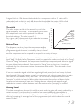
System 9098
Compressor
Limiter
by Rupert Neve the designer
User
Guide
Serial No: A
IMPORTANT
For convenience, write your serial number in the box above and
keep this guide in a safe place. The number can be found on the
rear of the product and also on the Authentification Certificate.
This number MUST be quoted in all communications in order to
obtain technical support and spare parts from either the factory or
your dealer.
1
© Harman International Industries Ltd. 1997
All rights reserved.
Parts of the design of this product may be protected by worldwide patents.
AMEK is a trading division of Harman International Industries Ltd.
Information contained in this manual is subject to change without notice and does
not represent a commitment on the part of the vendor. AMEK shall not be liable
for any loss or damage whatsoever arising from the use of information or any
error contained in this manual or through any mis-operation or fault in hardware
or software contained in the product.
No part of this manual may be reproduced, stored in a retrieval system,
transmitted in any form or by any means, electronic, electrical, mechanical,
optical, chemical, including photocopying and recording, for any purpose
whatsoever without the express written permission of AMEK.
It is recommended that all maintenance and service on the product should be
carried out by AMEK or it's authorised agents. AMEK cannot accept any liability
whatsoever for any loss or damage caused by service, maintenance or repair by
unauthorised personnel.
Part No: MANRNCL
2
Issue 3
Harman International Industries Ltd
Langley House
Third Avenue
Trafford Park
Manchester M17 1FG
United Kingdom
Tel: +44 (0) 161 868 2400
Fax: +44 (0) 161 873 8010
E-mail: [email protected]
Web: www.amek.com
Contents
Unpacking
Safety
Installation
Audio Connections
Overview
Block Diagram
Operational Guide
Specifications
Warranty
4
Safety symbols
Earthing
Changing the fuse
5
Mains Cable
100V/220V operation
7
Location
Rack mounting
Power up and clicks
Cleaning
10
11
by Rupert Neve
12
15
Compressor Controls
16
Limiter Controls
18
Ambience
19
Meter Controls
21
Master Controls
10dB Pad
ST Link
22
23
24
3
Unpacking
Check List
The following items are included with the
product.
It is recommended that packaging
materials are retained until all expected
items are accounted for and found to be
operating correctly.
Carton
Packet containing:
4 off M6 mounting screws
4 off plastic washers
1 off fuse for 110V operation.
Moulded
IEC
mains lead
Quality
Certificate
Compressor/Limiter
User
Guide
Protective foam
materials
4
IMPORTANT SAFETY INSTRUCTIONS
Safety
Caution
For your own safety and to avoid invalidation of warranty, all text
marked with these Safety Symbols should be read carefully!
Please keep this information!
Important
information.
Read this before
proceeding.
Caution
Hazards or unsafe
practices which can
result in severe
personal injury or
death.
Warning
Hazards or unsafe
practices which can
result in minor personal
injury or product or
property damage.
Important
Please read this manual carefully before connecting this apparatus to the mains
for the first time! Obey the following safety instructions. Read and understand
these instructions before operating the apparatus or doing troubleshooting,
testing, adjustments or repairs. Failure to comply with the safety instructions
may result in personal injury.
CAUTION
RISK OF ELECTRIC SHOCK
DO NOT OPEN
!
Caution - Earthing
This apparatus MUST be earthed. Under no circumstances should the mains
earth be disconnected from the mains lead.
Caution - Changing the Fuse
To avoid the risk of fire replace only with same value and type of fuse as
marked on the unit, 500mA T (220V) or 1A T (100V). Fuses are 20mm antisurge, IEC type.
Before changing the fuse, always switch off the unit and remove the AC power
cable! Locate the flap above the IEC connector and open it using a small
screwdriver. Fit the appropriate fuse supplied in the fixings pack and close the
flap.
5
Safety
WARNING - For your own safety and to avoid invalidation of the
warranty please read this section carefully.
!
!
!
!
!
!
!
!
!
!
!
!
!
!
!
6
Do not place the apparatus on an unstable surface.
Do not insert objects through any apertures.
Do not use this apparatus near water.
Unplug the unit before cleaning. Clean only with a damp cloth.
Do not block any of the ventilation openings. Install in accordance with the
manufacturer's instructions.
Do not install near any heat sources such as radiators, heat registers, stoves
or other apparatus including amplifiers or power supplies that produce heat.
Do not defeat the safety purpose of the polarised or grounding-type plug.
A polarised plug has two blades with one wider than the other.
A grounding-type plug has two blades and a third grounding prong. The
wider blade or the third prong are provided for your safety. When the plug
provided does not fit into your outlet, consult an electrician for replacement
of the obsolete outlet.
Protect the power cord from being walked on or pinched particularly at
plugs, convenience receptacles and the point where they exit from the
apparatus.
Avoid using mains outlets on the same circuits as air control systems or
other equipment that regularly switches on and off.
Only use attachments /accessories specified by the manufacturer.
Unplug this apparatus during lightning storms or when unused for long
periods of time.
Refer all servicing to qualified service personnel. Servicing is required when
the apparatus has been damaged in any way such as the power supply cord
or plug is damaged liquid has been spilled or objects have fallen into the
apparatus the apparatus has been exposed to rain or moisture the
apparatus does not operate normally the apparatus has been dropped.
Unplug the unit under these circumstances.
Adjust only those controls that are covered by the operating instructions.
Use only the mains lead provided with the equipment . Other leads may
not have sufficient current rating.
Do not operate this unit with the cover removed.
IMPORTANT SAFETY INSTRUCTIONS
Mains Cable
The supplied IEC mains cable must be terminated correctly to the AC mains
supply before use. Use only an approved AC plug or power distribution
device. The three cores are colour coded as follows:
Green/Yellow
Brown
Blue
=
=
=
Safety Earth
Live
Neutral
The Green/Yellow core in the mains
cable is a safety ground and must be
connected at all times!
100V/220V Operation
Before adjusting the operating voltage, always switch off the unit and
remove the AC power cable!
Locate the flap above the IEC connector and open it using a small screwdriver.
Remove the barrel and replace it so that the correct voltage marking is
outermost, then close the flap. The new voltage setting should be visible
through the window. Fit the appropriate fuse supplied in the fixings pack.
7
Sécurité
Précaution
Pour votre sécurité et afin de ne pas interrompre la garantie il est important
de lire attentivement les paragraphes marqués d'un symbole!
Conserver ce document!
Importante
information.
Priere de lire
avant utilisation.
Avis
Dangers ou pratiques
dangereuses pouvant
résulter en des
blessures graves ou
causant la mort.
Avertissement
Dangers ou pratiques
dangereuses pouvant
résulter en blessures
personnelles mineures
légères ou en
dommages à la
propriété.
Important
Ce manuel est à lire attentivement avant de brancher cet appareil pour la
première fois! Suivre les instructions de sécurité. Lire et comprendre ces
intructions avant l'utilisation de l'appareil ou avant dépannage, essai, ajustement
ou réparation. Ne pas se conformer aux instructions de sécurité peut
provoquer de graves blessures.
AVIS
RISQUE DE CHOC ELECTRIQUE
NE PAS OUVRIR
!
Avis - Terre
Cet appareil DOIT être mis à la terre. La mise à terre ne doit pas être
débranchée du terminal principal sous acune circonstance.
Avis - Changer le Fusible
8
Afin d'éviter un risque de feu, remplacer seulement avec fusible de la meme
valeur et type tel qu'indiqué sur l'appareil, 500mA T (220V) ou 1A T (100V).
Les fusibles sont de type IEC 20mm protection-surtension (pour fusibles).
Avant de changer le fusible, éteindre l'appareil et enlever la prise
d'alimentation!
Localisez le battement au-dessus du connecteur IEC et ouvrez-le utiliser un
petit tournevis. Allez parfaitement le fusible approprié fourni dans le paquet des
accessoires et fermez le battement.
INSTRUCTIONS DE SÉCURITÉ IMPORTANTES
Cable de Secteur
Le cable de secteur IEC fourni doit être correctement au cable d'alimentation
avant l'utilisation. Protéger le cordon d'alimentation afin d'éviter qu'il soit
piétiné, écrasé ou pincé, en particulier au niveau des prises de courant, des
fiches femelles et des points de sorties de l'appareil.
Utiliser seulement une prise de courant conforme. Les 3 cables à l'intérieur du
cable d'alimentation sont de couleurs suivantes:
Vert/Jaune
Marron
Bleu
=
=
=
Prise de Terre
Phase
Neutre
Le cable vert/jaune à
l'intérieur du cable
d'alimentation est la sécurité
terre et doit être toujours
connecté!
100V/220V Fonctionnement
Avant le réglage du voltage, toujours éteindre et débrancher l'appareil!
Localisez le battement au-dessus du connecteur IEC et ouvrez-le utiliser un
petit tournevis. Enlevez le baril et replacez-le afin que le voltage marquer
correct est le plus à l'extérieur, alors fermez le battement. Les nouveaux
voltage mettre devrait être visible à travers la fenêtre. Allez parfaitement le
fusible approprié fourni dans le paquet des accessoires.
9
Installation
Location
This product is designed and screened to minimise internal electromagnetic
emissions and provide immunity to external electromagnetic fields.
To reduce the risk of performance degradation due to external interference,
do not site this unit close to sources of strong magnetic fields such as power
supplies, power amplifiers, loudspeakers etc.
Rack Mounting
This product is designed to be rack mounted using the screws and washers
supplied to help preserve the finish of the facia panel.
The facia graphic layer is under-surface printed to provide a robust hard
wearing surface designed to last the life of the product in virtually any operating
environment. Failure to use the supplied fixings may result in damage to the
facia surface which can invalidate the warranty.
It is recommended that additional rack-mount side supports are used in
conjunction with the facia panel fixings, particularly when the unit is mounted in
a flite case or vehicle where vibration and transit shocks can be expected.
Powering up and Clicks
Clicks may be heard from in/out switches when the product is powered up,
these will dissipate after approximately 10 minutes. This is perfectly normal.
Cleaning
Unplug the unit before cleaning. The product should be cleaned with a soft
brush around the controls. If the facia becomes dirty, use a damp cloth with a
little household soap to remove the dirt. DO NOT use solvent cleaners under
any circumstances or the facia may be permanently damaged and warranty
invalidated!
10
Audio Connections
Earth Link
The CHASSIS GROUND post is internally connected
to both the case and the safety earth.
If the link is removed for technical reasons (such as earth
loops), then the ANALOGUE GROUND post must be
wired separately to the installation technical earth point.
Audio Connections
Two identical sets of 3 pin XLR connectors are provided for each
compressor channel A and B. Inputs are female, outputs are male.
All connectors follow the European wiring convention:
Pin 1 = Screen
Pin 2 = Hot (+)
Pin 3 = Cold (-)
The main inputs and outputs are transformer balanced, the outputs
coupled using Rupert Neve's "tertiary feedback" output stage design.
The side chain inputs and outputs are electronically balanced using
Rupert's "TLA" transformer-like-amplifier design.
System Level Switch
Each compressor channel is fitted with a switch to change the
system operating level between +4dBu and -10dBv as required.
System levels can be changed independently allowing the unit to
be operated as two separate mono compressor/limiters or as a
stereo pair.
11
Overview
by
Rupert
Neve
Each section of the RNCL has a compressor and
a limiter which can be adjusted independently of
each other. The following discussion describes
the behaviour of compressors and limiters and
the purpose of each type of control.
Compression
For signals below a "certain" level, compressors provides a linear path allowing these signals
to pass without the gain being processed in any way. Once these signals exceed that
"certain" level, the gain is reduced in a controlled manner. The amount of gain reduction
depends on two variables, ratio and threshold.
1:1
+25
+20
OUTPUT LEVEL (dBu)
Ratio
To describe "ratio" we will assume that the threshold
remains fixed. The gain reduction applied can be either
gentle or more severe. The most gentle, of course, is no
reduction at all and this occurs if the ratio is set at 1:1.
The ratio is sometime referred to as the "slope" as
shown on the graph. This shows how the output level
varies with input level at different ratio settings. The
threshold is set at 0dBu.
+15
2:1
+10
5:1
+5
16:1
0
-5
-10
-15
-20
-20 -15 -10
-5
0 +5 +10 +15 +20 +25
INPUT LEVEL (dBu)
Gain reduction (compression) is the difference between
what the output level would be without compression
and the actual output. On the graph it is the distance between the 1:1 line and output for
that input level. Signals are reduced in a logarithmic manner i.e. the reduction is based on
dBs, not voltages.
12
A signal which is 10dB above the threshold on a compressor with a 5:1 ratio will be
reduced in level so that it is only 2dB above the threshold at the output. With a fixed
threshold, the amount of gain reduction increases with higher ratio settings.
+25
OUTPUT LEVEL (dBu)
Threshold
The other major variable is the amount by which the
signal exceeds a "threshold". The illustration shows how
the output level varies with input level for different
threshold settings. The ratio is set at 5:1.
For a given ratio, the amount of gain reduction increases
with lower threshold settings.
+20
+20 dBu
+15
+15 dBu
+10
+10 dBu
+5
+5 dBu
0
0 dBu
-5
-10
Release Time
-15
The diagrams can show how the compressor handles
-20
-20 -15 -10
signals of constant amplitude, such as pure tones. Real
programme signals however, continually change in level
and the compressor can be required to respond in a variety of ways.
All ratios (slopes) 5:1
-5
0 +5 +10 +15 +20 +25
INPUT LEVEL (dBu)
For example, consider a programme with fairly constant level but which contains a short
loud "bang". It's likely that a compressor would be required to reduce the level of the "bang".
Once the "bang" has passed, the compressor should stop compressing and allow the signal
to pass without being reduced. If we expect the "bang" to be a short one, it would be
preferable for the compressor to stop compressing quite quickly. This is termed a "short
release time".
If we now consider a signal which has regular high level pulses (such as a heavy rhythmic
bass line) and if this signal passes through a compressor with a short release time, the gain
will return to normal after every bass note. This can create an unpleasant effect called
"pumping" in which the level of all the other instruments is forced up and down by the
compressor between each bass note. Setting a slower release time causes the gain
reduction to remain in effect between each bass note and the "pumping" is reduced.
Average Level
This latter example also shows that until the music ends, the gain will remain reduced by a
certain amount. It can therefore be useful to have some additional gain available to
compensate for this reduction. Using compression together with "make up" gain has the
effect of increasing the average level of the programme signal which makes the material
sound "louder".
13
Overview
Attack Time
The compressor "attack" control adjusts the rate at which it begins to compress. If it is set to
a short time (fast attack), gain changes occur quickly. Slower attack times mean that gain
reduction hardly occurs at all before the transient has passed. Typical programme material
contains transients ("spikes") which may cause gain reduction to occur. Some of these
transients will be extremely fast and have very little effect on the sound of the signal. Setting
a long attack time means that virtually no gain reduction occurs because the transient has
passed before compression has had time to build up.
Limiting
Limiting also provides a form of compression but one with an extremely high and fixed ratio.
The RNCL has a ratio of in excess of 100:1. As with the compressor, the point at which
gain reduction occurs is variable. The limiter ratio is extremely high which means that the
threshold is effectively the maximum level that can be output and is therefore labelled
"level". The limiter behaviour is based on the "peak" value of the input signal, unlike the
compressor which uses an RMS rectifier.
A typical signal may benefit from compression beginning
at a modest level and with a gentle slope. If the input
level exceeds a second threshold, the limiter can prevent
further output increases. The diagram shows typical
curves that might be used.
14
+25
+20
OUTPUT LEVEL (dBu)
Combining Compression and Limiting
The RNCL has been designed to provide a flexible gain
reduction tool. In many cases, a combination of
compression and limiting can be useful.
+15
Compressor threshold is -5 dBu, ratio 2:1
Limiter level is +6 dBu
Limiting
+10
+5
0
Compression
-5
-10
-15
Linear
-20
-20 -15 -10
-5
0 +5 +10 +15 +20 +25
INPUT LEVEL (dBu)
Output
Side Chain
Input
Gain Reduction
Xlr 3M
Xlr 3F
Symbol key
Side Chain
Return
TLA Input
Line
Transformer
Input
+4dBu
-10dBv
Meter Select
Insert In
+4dBu
-10dBv
TLA Output
VU Meter
RMS
Detector
Peak
Detector
Side Chain
Send
VCA
+4dBu
-10dBv
Faceplate
Controls
A/D
Transformer
D/A
CPU
Background
Processor
Output
D/A
Ambience
Block Diagram
15
Operational Guide
Attack
Threshold
Adjusts the level setting at which
gain reduction begins to occur.
Changes the time over which
compression begins to occur.
Release
Determines the time taken for
gain reduction to stop being
applied.
Ratio
Changes the severity of gain
reduction once the signal
exceeds the threshold setting.
In
Switches the compressor section
into circuit. This is independent
from the limiter section.
Compressor
Hard Knee
Selects a different shape to the compression
curve. When not selected, compression
begins gradually as the signal exceeds the
threshold. It only reaches the set ratio
several dB above the threshold. Selecting
Hard Knee makes the change less gradual.
16
Auto
The release time can be made
variable depending upon the
signal causing the compression.
Short term overloads will release
quickly and long term overloads
more slowly.
Side Chain In
Both channels of the RNCL use two audio paths. The
primary path carries the input signal, passes it through
the gain reduction device and provides the output. The
secondary path receives the same input signal but
processes it to determine the gain reduction to be
applied. This path is called the "side chain".
Compressor
Selecting "Side Chain In" allows equalisers or delays to be
inserted into the side chain which feeds the compressor. This
means gain reduction can be frequency dependent.
LF cut can be applied to the side chain to prevent a bass line
"pumping" the overall signal level. Alternatively, HF boost can be
applied which will make the compressor act more severely on
high frequency signals. This can be used to "de-ess" over sibilant
signals.
17
Operational Guide
Level
Sets the maximum signal level
which passes through the limiter.
Release
Changes the time taken for gain reduction
to return to zero after limiting.
Fast Attack
Selecting "fast" allows even short term
transients to cause gain reduction.
Limiter
Output Gain
Compression and limiting cause the output signal
level to be reduced. In many cases, it is not the
overall reduction in level which is required but a
reduction of the difference between the high
and low levels. The drop in output level can
therefore be compensated for, using the output
gain control.
18
The output gain control only affects the output
when either limiting or compression is switched
in. This means that the difference between the
compressed and direct signal can be heard,
without a serious change in the perceived
volume. The output gain control also has a
particular role when using the ambience mode.
Ambience
The ambience switch is a unique feature of
the RNCL which allows background
(ambient) noise to be reduced and is best
understood by listening to it.
When ambience is selected, the output
signal is neither the compressed/limited
signal nor the input signal, it is the difference
between them.
If controls are adjusted so that no gain
reduction takes place, the input and the
output signals are identical with the
difference between them being zero.
With "ambience" selected, the output will
also be zero i.e. silence. Note that under
some conditions, the phase of the signal
passing through will be altered.
Comp/Limiter
For ambience mode to have any effect, the
signal must undergo gain reduction using any
combination of compression or limiting,
therefore all the compressor/limiter controls
influence the ambience effect.
Adjusting the output gain changes the
balance between the compressed/limited
output and input signals and therefore
has a major effect on the behaviour of
ambience mode.
19
Operational Guide
Applications
A variety of special effects can be
created using the ambience mode. One
of the most useful is a reduction in the
background audio that may be behind
a "foreground" signal. The limiter mode
can be used, but more gentle effects
can be achieved using the compressor.
Before switching to ambience mode, the
compressor should be adjusted to give a
modest degree of compression, perhaps
peaking at around 10dB. For now, leave
the output gain control at the centre (0)
mark. Switch in the ambience mode and
adjust the output gain control until a
useful effect is obtained. The compressor
characteristics can also be changed as
required.
Comp/Limiter
With care, a form of gain reduction can
be achieved which reduces the audio in
the gaps between the main signal. This
description could also apply to the
behaviour of an expander or gate but it
is important to note that ambience is
not the same as either of these effects.
20
With the ambience effect, the degree of
gain reduction is a function of the high
level components of the input signal. The
greater these are, the greater the degree
of gain reduction (the more severe the
compression when ambience is switched
out).
Expansion or gating, attenuates the signal
path either by a preset amount or by an
amount based on the low level
components of the input.
Gain reduction
When selected to "G/R" the meter indicates '0'
in the absence of an input signal or any gain
reduction. If the signal exceeds the compression
threshold or limit level, the amount of gain
reduction is displayed.
In ambience mode, the meter continues
to show the amount of compression or
limiting, but due to the nature of the
ambience mode, no longer reads the
reduction in the output signal level.
Meters
I/P
The meter displays the input signal
level and is calibrated to show '0'
for signals of +4dBu.
S/C
O/P
The output signal level is
displayed. The calibration is the
same as for reading input.
S/C metering allows the input to
the side chain XLR input to be
displayed, whether "side chain" is
selected or not.
21
Operational Guide
10dB Pad
The meter pad reduces the reading of both
A and B VU meters when in I/P, O/P or S/C
modes.
When enabled, meter readings are reduced
by 10dB. '0' then represents +14dBu.
Master Controls
ST Link
When enabled, identical gain reduction takes place in
both A and B channel paths.
Compression and/or limiting is selected for both paths
at the same time and the characteristics for both paths
are adjusted from the A path controls.
The gain reduction applied is derived from whichever
path has the greatest signal.
22
Specifications
Noise - 150R source. Measured with RMS rectifier, 22Hz - 22kHz filter.
No lim/comp in circuit
Lim and/or comp. in circuit
-100 dBu
-92 dBu
Frequency Response -
measured from a 150R source and driving a 10K load.
Compressor & limiter in circuit but no gain reduction
20Hz - 20kHz
+/-0.2dB
<10Hz and >120 kHz
-3dB
THD + Noise - 1kHz tone from a 150R source and driving a 10K load.
+20dBu output - no comp/limiter in circuit
+20dBu i/p compressed @ 3:1 to give +10dBu o/p
+20dBu i/p limited to give +10dBu o/p
0.002%
0.03%
0.03%
Crosstalk - One channel i/p @ +20dBu. Signal (w.r.t. +20dBu) measured at other output.
better than 105dB at 20Hz and 1kHz
better than 90dB at 20kHz
Note: Figures apply whether or not limiting/compression is enabled.
Mechanical - Dimensions and Weight
Size
19" 2U rack unit. (482 x 89mm)
Depth including connectors 420mm
Weight
8.74kg
Power Consumption
15W (typical)
Notes
1. All specifications are subject to change without notice.
2. Figures quoted are measured on a normal production sample and typical of
performance normally achieved, however, they do not constitute a guaranteed
23
Warranty
1. Amek is a trading division of Harman International Industries Ltd.
End User means the person who first puts the equipment into regular operation.
Dealer means the person other than Amek (if any) from whom the End User purchased the
equipment, provided such a person is authorised for this purpose by Amek or it’s accredited
Distributor.
Equipment means the equipment supplied with this manual.
2. If within the period of twelve months from the date of delivery of the Equipment to the End
User it shall prove defective by reason only of faulty materials and/or workmanship to such an
extent that the effectiveness and/or usability thereof is materially affected, the Equipment or the
defective component should be returned to the Dealer or to Amek and subject to the following
conditions, the Dealer or Amek will repair or replace the defective components. Any components
replaced will become the property of Amek.
3. Any Equipment or component returned will be at the risk of the End User whilst in transit (both
to and from the Dealer or Amek) and postage/shipping must be prepaid.
4. This warranty shall only be available if:
a) The Equipment has been properly installed in accordance with instructions contained
in Amek’s manual; and
b) The End User has notified Amek or the Dealer within 14 days of the defect
appearing; and
c) No persons other than the authorised representatives of Amek or the Dealer have
effected any replacement of parts, maintenance adjustments or repairs to the
Equipment; and
d) The End User has used the Equipment only for such purposes as Amek
recommends, with only such operating supplies as meet Amek’s specifications and
otherwise in all respects in accordance with Amek’s recommendations.
5. Defects arising as a result of the following are not covered by this Warranty:
Faulty or negligent handling, chemical or electro-chemical or electrical influences, accidental
damage, Acts of God, neglect, deficiency in electrical power, air-conditioning or humidity control.
6. The benefit of this Warranty may not be assigned by the End User.
7. End Users who are consumers should note their rights under this Warranty are in addition to
and do not affect any other rights to which they may be entitled against the seller of the
Equipment.
24