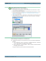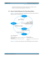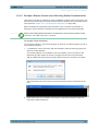
1
R&S®SGU100A SGMA Upconverter User Manual (;ÚÛJ2) User Manual Test & Measurement 1176.7726.02 ─ 06 This document describes the R&S®SGU100A, stock no. 1418.2005.02 and its options. ● R&S®SGU-B26 (1418.3401.02) ● R&S®SGU-B120/120V (1418.2605.02/1418.2657.02) ● R&S®SGU-B140/140V (1418.2870.02/1418.2928.02 ) The firmware of the instrument makes use of the operating system LINUX® and other valuable open source software packages. For information, see the "Open Source Acknowledgement" on the user documentation CD-ROM (included in delivery). Rohde & Schwarz would like to thank the open source community for their valuable contribution to embedded computing. © 2015 Rohde & Schwarz GmbH & Co. KG Mühldorfstr. 15, 81671 München, Germany Phone: +49 89 41 29 - 0 Fax: +49 89 41 29 12 164 Email: [email protected] Internet: www.rohde-schwarz.com Subject to change – Data without tolerance limits is not binding. R&S® is a registered trademark of Rohde & Schwarz GmbH & Co. KG. Trade names are trademarks of the owners. The following abbreviations are used throughout this manual: R&S®SGU100A is abbreviated as R&S SGU, R&S®SGS100A is abbreviated as R&S SGS, R&S®SGMA-GUI is abbreviated as R&S SGMA-GUI, R&S®FSW is abbreviated as R&S FSW. Basic Safety Instructions Always read through and comply with the following safety instructions! All plants and locations of the Rohde & Schwarz group of companies make every effort to keep the safety standards of our products up to date and to offer our customers the highest possible degree of safety. Our products and the auxiliary equipment they require are designed, built and tested in accordance with the safety standards that apply in each case. Compliance with these standards is continuously monitored by our quality assurance system. The product described here has been designed, built and tested in accordance with the EC Certificate of Conformity and has left the manufacturer’s plant in a condition fully complying with safety standards. To maintain this condition and to ensure safe operation, you must observe all instructions and warnings provided in this manual. If you have any questions regarding these safety instructions, the Rohde & Schwarz group of companies will be happy to answer them. Furthermore, it is your responsibility to use the product in an appropriate manner. This product is designed for use solely in industrial and laboratory environments or, if expressly permitted, also in the field and must not be used in any way that may cause personal injury or property damage. You are responsible if the product is used for any purpose other than its designated purpose or in disregard of the manufacturer's instructions. The manufacturer shall assume no responsibility for such use of the product. The product is used for its designated purpose if it is used in accordance with its product documentation and within its performance limits (see data sheet, documentation, the following safety instructions). Using the product requires technical skills and, in some cases, a basic knowledge of English. It is therefore essential that only skilled and specialized staff or thoroughly trained personnel with the required skills be allowed to use the product. If personal safety gear is required for using Rohde & Schwarz products, this will be indicated at the appropriate place in the product documentation. Keep the basic safety instructions and the product documentation in a safe place and pass them on to the subsequent users. Observing the safety instructions will help prevent personal injury or damage of any kind caused by dangerous situations. Therefore, carefully read through and adhere to the following safety instructions before and when using the product. It is also absolutely essential to observe the additional safety instructions on personal safety, for example, that appear in relevant parts of the product documentation. In these safety instructions, the word "product" refers to all merchandise sold and distributed by the Rohde & Schwarz group of companies, including instruments, systems and all accessories. For product-specific information, see the data sheet and the product documentation. Safety labels on products The following safety labels are used on products to warn against risks and dangers. Symbol Meaning Notice, general danger location Symbol Meaning ON/OFF Power Observe product documentation Caution when handling heavy equipment Standby indication Danger of electric shock Direct current (DC) 1171.0000.42 - 08 Page 1 Basic Safety Instructions Symbol Meaning Symbol Meaning Caution ! Hot surface Alternating current (AC) Protective conductor terminal To identify any terminal which is intended for connection to an external conductor for protection against electric shock in case of a fault, or the terminal of a protective earth Direct/alternating current (DC/AC) Earth (Ground) Class II Equipment to identify equipment meeting the safety requirements specified for Class II equipment (device protected by double or reinforced insulation) Frame or chassis Ground terminal EU labeling for batteries and accumulators For additional information, see section "Waste disposal/Environmental protection", item 1. Be careful when handling electrostatic sensitive devices EU labeling for separate collection of electrical and electronic devices For additional information, see section "Waste disposal/Environmental protection", item 2. Warning! Laser radiation For additional information, see section "Operation", item 7. Signal words and their meaning The following signal words are used in the product documentation in order to warn the reader about risks and dangers. Indicates a hazardous situation which, if not avoided, will result in death or serious injury. Indicates a hazardous situation which, if not avoided, could result in death or serious injury. Indicates a hazardous situation which, if not avoided, could result in minor or moderate injury. Indicates information considered important, but not hazard-related, e.g. messages relating to property damage. In the product documentation, the word ATTENTION is used synonymously. These signal words are in accordance with the standard definition for civil applications in the European Economic Area. Definitions that deviate from the standard definition may also exist in other economic areas or military applications. It is therefore essential to make sure that the signal words described here are always used only in connection with the related product documentation and the related product. The use of signal words in connection with unrelated products or documentation can result in misinterpretation and in personal injury or material damage. 1171.0000.42 - 08 Page 2 Basic Safety Instructions Operating states and operating positions The product may be operated only under the operating conditions and in the positions specified by the manufacturer, without the product's ventilation being obstructed. If the manufacturer's specifications are not observed, this can result in electric shock, fire and/or serious personal injury or death. Applicable local or national safety regulations and rules for the prevention of accidents must be observed in all work performed. 1. Unless otherwise specified, the following requirements apply to Rohde & Schwarz products: predefined operating position is always with the housing floor facing down, IP protection 2X, use only indoors, max. operating altitude 2000 m above sea level, max. transport altitude 4500 m above sea level. A tolerance of ±10 % shall apply to the nominal voltage and ±5 % to the nominal frequency, overvoltage category 2, pollution degree 2. 2. Do not place the product on surfaces, vehicles, cabinets or tables that for reasons of weight or stability are unsuitable for this purpose. Always follow the manufacturer's installation instructions when installing the product and fastening it to objects or structures (e.g. walls and shelves). An installation that is not carried out as described in the product documentation could result in personal injury or even death. 3. Do not place the product on heat-generating devices such as radiators or fan heaters. The ambient temperature must not exceed the maximum temperature specified in the product documentation or in the data sheet. Product overheating can cause electric shock, fire and/or serious personal injury or even death. Electrical safety If the information on electrical safety is not observed either at all or to the extent necessary, electric shock, fire and/or serious personal injury or death may occur. 1. Prior to switching on the product, always ensure that the nominal voltage setting on the product matches the nominal voltage of the mains-supply network. If a different voltage is to be set, the power fuse of the product may have to be changed accordingly. 2. In the case of products of safety class I with movable power cord and connector, operation is permitted only on sockets with a protective conductor contact and protective conductor. 3. Intentionally breaking the protective conductor either in the feed line or in the product itself is not permitted. Doing so can result in the danger of an electric shock from the product. If extension cords or connector strips are implemented, they must be checked on a regular basis to ensure that they are safe to use. 4. If there is no power switch for disconnecting the product from the mains, or if the power switch is not suitable for this purpose, use the plug of the connecting cable to disconnect the product from the mains. In such cases, always ensure that the power plug is easily reachable and accessible at all times. For example, if the power plug is the disconnecting device, the length of the connecting cable must not exceed 3 m. Functional or electronic switches are not suitable for providing disconnection from the AC supply network. If products without power switches are integrated into racks or systems, the disconnecting device must be provided at the system level. 5. Never use the product if the power cable is damaged. Check the power cables on a regular basis to ensure that they are in proper operating condition. By taking appropriate safety measures and carefully laying the power cable, ensure that the cable cannot be damaged and that no one can be hurt by, for example, tripping over the cable or suffering an electric shock. 1171.0000.42 - 08 Page 3 Basic Safety Instructions 6. The product may be operated only from TN/TT supply networks fuse-protected with max. 16 A (higher fuse only after consulting with the Rohde & Schwarz group of companies). 7. Do not insert the plug into sockets that are dusty or dirty. Insert the plug firmly and all the way into the socket provided for this purpose. Otherwise, sparks that result in fire and/or injuries may occur. 8. Do not overload any sockets, extension cords or connector strips; doing so can cause fire or electric shocks. 9. For measurements in circuits with voltages Vrms > 30 V, suitable measures (e.g. appropriate measuring equipment, fuse protection, current limiting, electrical separation, insulation) should be taken to avoid any hazards. 10. Ensure that the connections with information technology equipment, e.g. PCs or other industrial computers, comply with the IEC 60950-1 / EN 60950-1 or IEC 61010-1 / EN 61010-1 standards that apply in each case. 11. Unless expressly permitted, never remove the cover or any part of the housing while the product is in operation. Doing so will expose circuits and components and can lead to injuries, fire or damage to the product. 12. If a product is to be permanently installed, the connection between the protective conductor terminal on site and the product's protective conductor must be made first before any other connection is made. The product may be installed and connected only by a licensed electrician. 13. For permanently installed equipment without built-in fuses, circuit breakers or similar protective devices, the supply circuit must be fuse-protected in such a way that anyone who has access to the product, as well as the product itself, is adequately protected from injury or damage. 14. Use suitable overvoltage protection to ensure that no overvoltage (such as that caused by a bolt of lightning) can reach the product. Otherwise, the person operating the product will be exposed to the danger of an electric shock. 15. Any object that is not designed to be placed in the openings of the housing must not be used for this purpose. Doing so can cause short circuits inside the product and/or electric shocks, fire or injuries. 16. Unless specified otherwise, products are not liquid-proof (see also section "Operating states and operating positions", item 1). Therefore, the equipment must be protected against penetration by liquids. If the necessary precautions are not taken, the user may suffer electric shock or the product itself may be damaged, which can also lead to personal injury. 17. Never use the product under conditions in which condensation has formed or can form in or on the product, e.g. if the product has been moved from a cold to a warm environment. Penetration by water increases the risk of electric shock. 18. Prior to cleaning the product, disconnect it completely from the power supply (e.g. AC supply network or battery). Use a soft, non-linting cloth to clean the product. Never use chemical cleaning agents such as alcohol, acetone or diluents for cellulose lacquers. Operation 1. Operating the products requires special training and intense concentration. Make sure that persons who use the products are physically, mentally and emotionally fit enough to do so; otherwise, injuries or material damage may occur. It is the responsibility of the employer/operator to select suitable personnel for operating the products. 1171.0000.42 - 08 Page 4 Basic Safety Instructions 2. Before you move or transport the product, read and observe the section titled "Transport". 3. As with all industrially manufactured goods, the use of substances that induce an allergic reaction (allergens) such as nickel cannot be generally excluded. If you develop an allergic reaction (such as a skin rash, frequent sneezing, red eyes or respiratory difficulties) when using a Rohde & Schwarz product, consult a physician immediately to determine the cause and to prevent health problems or stress. 4. Before you start processing the product mechanically and/or thermally, or before you take it apart, be sure to read and pay special attention to the section titled "Waste disposal/Environmental protection", item 1. 5. Depending on the function, certain products such as RF radio equipment can produce an elevated level of electromagnetic radiation. Considering that unborn babies require increased protection, pregnant women must be protected by appropriate measures. Persons with pacemakers may also be exposed to risks from electromagnetic radiation. The employer/operator must evaluate workplaces where there is a special risk of exposure to radiation and, if necessary, take measures to avert the potential danger. 6. Should a fire occur, the product may release hazardous substances (gases, fluids, etc.) that can cause health problems. Therefore, suitable measures must be taken, e.g. protective masks and protective clothing must be worn. 7. Laser products are given warning labels that are standardized according to their laser class. Lasers can cause biological harm due to the properties of their radiation and due to their extremely concentrated electromagnetic power. If a laser product (e.g. a CD/DVD drive) is integrated into a Rohde & Schwarz product, absolutely no other settings or functions may be used as described in the product documentation. The objective is to prevent personal injury (e.g. due to laser beams). 8. EMC classes (in line with EN 55011/CISPR 11, and analogously with EN 55022/CISPR 22, EN 55032/CISPR 32) Class A equipment: Equipment suitable for use in all environments except residential environments and environments that are directly connected to a low-voltage supply network that supplies residential buildings Note: Class A equipment is intended for use in an industrial environment. This equipment may cause radio disturbances in residential environments, due to possible conducted as well as radiated disturbances. In this case, the operator may be required to take appropriate measures to eliminate these disturbances. Class B equipment: Equipment suitable for use in residential environments and environments that are directly connected to a low-voltage supply network that supplies residential buildings Repair and service 1. The product may be opened only by authorized, specially trained personnel. Before any work is performed on the product or before the product is opened, it must be disconnected from the AC supply network. Otherwise, personnel will be exposed to the risk of an electric shock. 1171.0000.42 - 08 Page 5 Basic Safety Instructions 2. Adjustments, replacement of parts, maintenance and repair may be performed only by electrical experts authorized by Rohde & Schwarz. Only original parts may be used for replacing parts relevant to safety (e.g. power switches, power transformers, fuses). A safety test must always be performed after parts relevant to safety have been replaced (visual inspection, protective conductor test, insulation resistance measurement, leakage current measurement, functional test). This helps ensure the continued safety of the product. Batteries and rechargeable batteries/cells If the information regarding batteries and rechargeable batteries/cells is not observed either at all or to the extent necessary, product users may be exposed to the risk of explosions, fire and/or serious personal injury, and, in some cases, death. Batteries and rechargeable batteries with alkaline electrolytes (e.g. lithium cells) must be handled in accordance with the EN 62133 standard. 1. Cells must not be taken apart or crushed. 2. Cells or batteries must not be exposed to heat or fire. Storage in direct sunlight must be avoided. Keep cells and batteries clean and dry. Clean soiled connectors using a dry, clean cloth. 3. Cells or batteries must not be short-circuited. Cells or batteries must not be stored in a box or in a drawer where they can short-circuit each other, or where they can be short-circuited by other conductive materials. Cells and batteries must not be removed from their original packaging until they are ready to be used. 4. Cells and batteries must not be exposed to any mechanical shocks that are stronger than permitted. 5. If a cell develops a leak, the fluid must not be allowed to come into contact with the skin or eyes. If contact occurs, wash the affected area with plenty of water and seek medical aid. 6. Improperly replacing or charging cells or batteries that contain alkaline electrolytes (e.g. lithium cells) can cause explosions. Replace cells or batteries only with the matching Rohde & Schwarz type (see parts list) in order to ensure the safety of the product. 7. Cells and batteries must be recycled and kept separate from residual waste. Rechargeable batteries and normal batteries that contain lead, mercury or cadmium are hazardous waste. Observe the national regulations regarding waste disposal and recycling. Transport 1. The product may be very heavy. Therefore, the product must be handled with care. In some cases, the user may require a suitable means of lifting or moving the product (e.g. with a lift-truck) to avoid back or other physical injuries. 2. Handles on the products are designed exclusively to enable personnel to transport the product. It is therefore not permissible to use handles to fasten the product to or on transport equipment such as cranes, fork lifts, wagons, etc. The user is responsible for securely fastening the products to or on the means of transport or lifting. Observe the safety regulations of the manufacturer of the means of transport or lifting. Noncompliance can result in personal injury or material damage. 3. If you use the product in a vehicle, it is the sole responsibility of the driver to drive the vehicle safely and properly. The manufacturer assumes no responsibility for accidents or collisions. Never use the product in a moving vehicle if doing so could distract the driver of the vehicle. Adequately secure the product in the vehicle to prevent injuries or other damage in the event of an accident. 1171.0000.42 - 08 Page 6 Instrucciones de seguridad elementales Waste disposal/Environmental protection 1. Specially marked equipment has a battery or accumulator that must not be disposed of with unsorted municipal waste, but must be collected separately. It may only be disposed of at a suitable collection point or via a Rohde & Schwarz customer service center. 2. Waste electrical and electronic equipment must not be disposed of with unsorted municipal waste, but must be collected separately. Rohde & Schwarz GmbH & Co. KG has developed a disposal concept and takes full responsibility for take-back obligations and disposal obligations for manufacturers within the EU. Contact your Rohde & Schwarz customer service center for environmentally responsible disposal of the product. 3. If products or their components are mechanically and/or thermally processed in a manner that goes beyond their intended use, hazardous substances (heavy-metal dust such as lead, beryllium, nickel) may be released. For this reason, the product may only be disassembled by specially trained personnel. Improper disassembly may be hazardous to your health. National waste disposal regulations must be observed. 4. If handling the product releases hazardous substances or fuels that must be disposed of in a special way, e.g. coolants or engine oils that must be replenished regularly, the safety instructions of the manufacturer of the hazardous substances or fuels and the applicable regional waste disposal regulations must be observed. Also observe the relevant safety instructions in the product documentation. The improper disposal of hazardous substances or fuels can cause health problems and lead to environmental damage. For additional information about environmental protection, visit the Rohde & Schwarz website. Instrucciones de seguridad elementales ¡Es imprescindible leer y cumplir las siguientes instrucciones e informaciones de seguridad! El principio del grupo de empresas Rohde & Schwarz consiste en tener nuestros productos siempre al día con los estándares de seguridad y de ofrecer a nuestros clientes el máximo grado de seguridad. Nuestros productos y todos los equipos adicionales son siempre fabricados y examinados según las normas de seguridad vigentes. Nuestro sistema de garantía de calidad controla constantemente que sean cumplidas estas normas. El presente producto ha sido fabricado y examinado según el certificado de conformidad de la UE y ha salido de nuestra planta en estado impecable según los estándares técnicos de seguridad. Para poder preservar este estado y garantizar un funcionamiento libre de peligros, el usuario deberá atenerse a todas las indicaciones, informaciones de seguridad y notas de alerta. El grupo de empresas Rohde & Schwarz está siempre a su disposición en caso de que tengan preguntas referentes a estas informaciones de seguridad. Además queda en la responsabilidad del usuario utilizar el producto en la forma debida. Este producto está destinado exclusivamente al uso en la industria y el laboratorio o, si ha sido expresamente autorizado, para aplicaciones de campo y de ninguna manera deberá ser utilizado de modo que alguna persona/cosa pueda sufrir daño. El uso del producto fuera de sus fines definidos o sin tener en cuenta las instrucciones del fabricante queda en la responsabilidad del usuario. El fabricante no se hace en ninguna forma responsable de consecuencias a causa del mal uso del producto. 1171.0000.42 - 08 Page 7 Instrucciones de seguridad elementales Se parte del uso correcto del producto para los fines definidos si el producto es utilizado conforme a las indicaciones de la correspondiente documentación del producto y dentro del margen de rendimiento definido (ver hoja de datos, documentación, informaciones de seguridad que siguen). El uso del producto hace necesarios conocimientos técnicos y ciertos conocimientos del idioma inglés. Por eso se debe tener en cuenta que el producto solo pueda ser operado por personal especializado o personas instruidas en profundidad con las capacidades correspondientes. Si fuera necesaria indumentaria de seguridad para el uso de productos de Rohde & Schwarz, encontraría la información debida en la documentación del producto en el capítulo correspondiente. Guarde bien las informaciones de seguridad elementales, así como la documentación del producto, y entréguelas a usuarios posteriores. Tener en cuenta las informaciones de seguridad sirve para evitar en lo posible lesiones o daños por peligros de toda clase. Por eso es imprescindible leer detalladamente y comprender por completo las siguientes informaciones de seguridad antes de usar el producto, y respetarlas durante el uso del producto. Deberán tenerse en cuenta todas las demás informaciones de seguridad, como p. ej. las referentes a la protección de personas, que encontrarán en el capítulo correspondiente de la documentación del producto y que también son de obligado cumplimiento. En las presentes informaciones de seguridad se recogen todos los objetos que distribuye el grupo de empresas Rohde & Schwarz bajo la denominación de "producto", entre ellos también aparatos, instalaciones así como toda clase de accesorios. Los datos específicos del producto figuran en la hoja de datos y en la documentación del producto. Señalización de seguridad de los productos Las siguientes señales de seguridad se utilizan en los productos para advertir sobre riesgos y peligros. Símbolo Significado Aviso: punto de peligro general Observar la documentación del producto Símbolo Significado Tensión de alimentación de PUESTA EN MARCHA / PARADA Atención en el manejo de dispositivos de peso elevado Indicación de estado de espera (standby) Peligro de choque eléctrico Corriente continua (DC) Advertencia: superficie caliente Corriente alterna (AC) Conexión a conductor de protección Corriente continua / Corriente alterna (DC/AC) Conexión a tierra El aparato está protegido en su totalidad por un aislamiento doble (reforzado) Conexión a masa Distintivo de la UE para baterías y acumuladores Más información en la sección "Eliminación/protección del medio ambiente", punto 1. 1171.0000.42 - 08 Page 8 Instrucciones de seguridad elementales Símbolo Significado Símbolo Aviso: Cuidado en el manejo de dispositivos sensibles a la electrostática (ESD) Significado Distintivo de la UE para la eliminación por separado de dispositivos eléctricos y electrónicos Más información en la sección "Eliminación/protección del medio ambiente", punto 2. Advertencia: rayo láser Más información en la sección "Funcionamiento", punto 7. Palabras de señal y su significado En la documentación del producto se utilizan las siguientes palabras de señal con el fin de advertir contra riesgos y peligros. Indica una situación de peligro que, si no se evita, causa lesiones graves o incluso la muerte. Indica una situación de peligro que, si no se evita, puede causar lesiones graves o incluso la muerte. Indica una situación de peligro que, si no se evita, puede causar lesiones leves o moderadas. Indica información que se considera importante, pero no en relación con situaciones de peligro; p. ej., avisos sobre posibles daños materiales. En la documentación del producto se emplea de forma sinónima el término CUIDADO. Las palabras de señal corresponden a la definición habitual para aplicaciones civiles en el área económica europea. Pueden existir definiciones diferentes a esta definición en otras áreas económicas o en aplicaciones militares. Por eso se deberá tener en cuenta que las palabras de señal aquí descritas sean utilizadas siempre solamente en combinación con la correspondiente documentación del producto y solamente en combinación con el producto correspondiente. La utilización de las palabras de señal en combinación con productos o documentaciones que no les correspondan puede llevar a interpretaciones equivocadas y tener por consecuencia daños en personas u objetos. Estados operativos y posiciones de funcionamiento El producto solamente debe ser utilizado según lo indicado por el fabricante respecto a los estados operativos y posiciones de funcionamiento sin que se obstruya la ventilación. Si no se siguen las indicaciones del fabricante, pueden producirse choques eléctricos, incendios y/o lesiones graves con posible consecuencia de muerte. En todos los trabajos deberán ser tenidas en cuenta las normas nacionales y locales de seguridad del trabajo y de prevención de accidentes. 1171.0000.42 - 08 Page 9 Instrucciones de seguridad elementales 1. Si no se convino de otra manera, es para los productos Rohde & Schwarz válido lo que sigue: como posición de funcionamiento se define por principio la posición con el suelo de la caja para abajo, modo de protección IP 2X, uso solamente en estancias interiores, utilización hasta 2000 m sobre el nivel del mar, transporte hasta 4500 m sobre el nivel del mar. Se aplicará una tolerancia de ±10 % sobre el voltaje nominal y de ±5 % sobre la frecuencia nominal. Categoría de sobrecarga eléctrica 2, índice de suciedad 2. 2. No sitúe el producto encima de superficies, vehículos, estantes o mesas, que por sus características de peso o de estabilidad no sean aptos para él. Siga siempre las instrucciones de instalación del fabricante cuando instale y asegure el producto en objetos o estructuras (p. ej. paredes y estantes). Si se realiza la instalación de modo distinto al indicado en la documentación del producto, se pueden causar lesiones o, en determinadas circunstancias, incluso la muerte. 3. No ponga el producto sobre aparatos que generen calor (p. ej. radiadores o calefactores). La temperatura ambiente no debe superar la temperatura máxima especificada en la documentación del producto o en la hoja de datos. En caso de sobrecalentamiento del producto, pueden producirse choques eléctricos, incendios y/o lesiones graves con posible consecuencia de muerte. Seguridad eléctrica Si no se siguen (o se siguen de modo insuficiente) las indicaciones del fabricante en cuanto a seguridad eléctrica, pueden producirse choques eléctricos, incendios y/o lesiones graves con posible consecuencia de muerte. 1. Antes de la puesta en marcha del producto se deberá comprobar siempre que la tensión preseleccionada en el producto coincida con la de la red de alimentación eléctrica. Si es necesario modificar el ajuste de tensión, también se deberán cambiar en caso dado los fusibles correspondientes del producto. 2. Los productos de la clase de protección I con alimentación móvil y enchufe individual solamente podrán enchufarse a tomas de corriente con contacto de seguridad y con conductor de protección conectado. 3. Queda prohibida la interrupción intencionada del conductor de protección, tanto en la toma de corriente como en el mismo producto. La interrupción puede tener como consecuencia el riesgo de que el producto sea fuente de choques eléctricos. Si se utilizan cables alargadores o regletas de enchufe, deberá garantizarse la realización de un examen regular de los mismos en cuanto a su estado técnico de seguridad. 4. Si el producto no está equipado con un interruptor para desconectarlo de la red, o bien si el interruptor existente no resulta apropiado para la desconexión de la red, el enchufe del cable de conexión se deberá considerar como un dispositivo de desconexión. El dispositivo de desconexión se debe poder alcanzar fácilmente y debe estar siempre bien accesible. Si, p. ej., el enchufe de conexión a la red es el dispositivo de desconexión, la longitud del cable de conexión no debe superar 3 m). Los interruptores selectores o electrónicos no son aptos para el corte de la red eléctrica. Si se integran productos sin interruptor en bastidores o instalaciones, se deberá colocar el interruptor en el nivel de la instalación. 5. No utilice nunca el producto si está dañado el cable de conexión a red. Compruebe regularmente el correcto estado de los cables de conexión a red. Asegúrese, mediante las medidas de protección y de instalación adecuadas, de que el cable de conexión a red no pueda ser dañado o de que nadie pueda ser dañado por él, p. ej. al tropezar o por un choque eléctrico. 1171.0000.42 - 08 Page 10 Instrucciones de seguridad elementales 6. Solamente está permitido el funcionamiento en redes de alimentación TN/TT aseguradas con fusibles de 16 A como máximo (utilización de fusibles de mayor amperaje solo previa consulta con el grupo de empresas Rohde & Schwarz). 7. Nunca conecte el enchufe en tomas de corriente sucias o llenas de polvo. Introduzca el enchufe por completo y fuertemente en la toma de corriente. La no observación de estas medidas puede provocar chispas, fuego y/o lesiones. 8. No sobrecargue las tomas de corriente, los cables alargadores o las regletas de enchufe ya que esto podría causar fuego o choques eléctricos. 9. En las mediciones en circuitos de corriente con una tensión U eff > 30 V se deberán tomar las medidas apropiadas para impedir cualquier peligro (p. ej. medios de medición adecuados, seguros, limitación de tensión, corte protector, aislamiento etc.). 10. Para la conexión con dispositivos informáticos como un PC o un ordenador industrial, debe comprobarse que éstos cumplan los estándares IEC60950-1/EN60950-1 o IEC61010-1/EN 61010-1 válidos en cada caso. 11. A menos que esté permitido expresamente, no retire nunca la tapa ni componentes de la carcasa mientras el producto esté en servicio. Esto pone a descubierto los cables y componentes eléctricos y puede causar lesiones, fuego o daños en el producto. 12. Si un producto se instala en un lugar fijo, se deberá primero conectar el conductor de protección fijo con el conductor de protección del producto antes de hacer cualquier otra conexión. La instalación y la conexión deberán ser efectuadas por un electricista especializado. 13. En el caso de dispositivos fijos que no estén provistos de fusibles, interruptor automático ni otros mecanismos de seguridad similares, el circuito de alimentación debe estar protegido de modo que todas las personas que puedan acceder al producto, así como el producto mismo, estén a salvo de posibles daños. 14. Todo producto debe estar protegido contra sobretensión (debida p. ej. a una caída del rayo) mediante los correspondientes sistemas de protección. Si no, el personal que lo utilice quedará expuesto al peligro de choque eléctrico. 15. No debe introducirse en los orificios de la caja del aparato ningún objeto que no esté destinado a ello. Esto puede producir cortocircuitos en el producto y/o puede causar choques eléctricos, fuego o lesiones. 16. Salvo indicación contraria, los productos no están impermeabilizados (ver también el capítulo "Estados operativos y posiciones de funcionamiento", punto 1). Por eso es necesario tomar las medidas necesarias para evitar la entrada de líquidos. En caso contrario, existe peligro de choque eléctrico para el usuario o de daños en el producto, que también pueden redundar en peligro para las personas. 17. No utilice el producto en condiciones en las que pueda producirse o ya se hayan producido condensaciones sobre el producto o en el interior de éste, como p. ej. al desplazarlo de un lugar frío a otro caliente. La entrada de agua aumenta el riesgo de choque eléctrico. 18. Antes de la limpieza, desconecte por completo el producto de la alimentación de tensión (p. ej. red de alimentación o batería). Realice la limpieza de los aparatos con un paño suave, que no se deshilache. No utilice bajo ningún concepto productos de limpieza químicos como alcohol, acetona o diluyentes para lacas nitrocelulósicas. 1171.0000.42 - 08 Page 11 Instrucciones de seguridad elementales Funcionamiento 1. El uso del producto requiere instrucciones especiales y una alta concentración durante el manejo. Debe asegurarse que las personas que manejen el producto estén a la altura de los requerimientos necesarios en cuanto a aptitudes físicas, psíquicas y emocionales, ya que de otra manera no se pueden excluir lesiones o daños de objetos. El empresario u operador es responsable de seleccionar el personal usuario apto para el manejo del producto. 2. Antes de desplazar o transportar el producto, lea y tenga en cuenta el capítulo "Transporte". 3. Como con todo producto de fabricación industrial no puede quedar excluida en general la posibilidad de que se produzcan alergias provocadas por algunos materiales empleados ―los llamados alérgenos (p. ej. el níquel)―. Si durante el manejo de productos Rohde & Schwarz se producen reacciones alérgicas, como p. ej. irritaciones cutáneas, estornudos continuos, enrojecimiento de la conjuntiva o dificultades respiratorias, debe avisarse inmediatamente a un médico para investigar las causas y evitar cualquier molestia o daño a la salud. 4. Antes de la manipulación mecánica y/o térmica o el desmontaje del producto, debe tenerse en cuenta imprescindiblemente el capítulo "Eliminación/protección del medio ambiente", punto 1. 5. Ciertos productos, como p. ej. las instalaciones de radiocomunicación RF, pueden a causa de su función natural, emitir una radiación electromagnética aumentada. Deben tomarse todas las medidas necesarias para la protección de las mujeres embarazadas. También las personas con marcapasos pueden correr peligro a causa de la radiación electromagnética. El empresario/operador tiene la obligación de evaluar y señalizar las áreas de trabajo en las que exista un riesgo elevado de exposición a radiaciones. 6. Tenga en cuenta que en caso de incendio pueden desprenderse del producto sustancias tóxicas (gases, líquidos etc.) que pueden generar daños a la salud. Por eso, en caso de incendio deben usarse medidas adecuadas, como p. ej. máscaras antigás e indumentaria de protección. 7. Los productos con láser están provistos de indicaciones de advertencia normalizadas en función de la clase de láser del que se trate. Los rayos láser pueden provocar daños de tipo biológico a causa de las propiedades de su radiación y debido a su concentración extrema de potencia electromagnética. En caso de que un producto Rohde & Schwarz contenga un producto láser (p. ej. un lector de CD/DVD), no debe usarse ninguna otra configuración o función aparte de las descritas en la documentación del producto, a fin de evitar lesiones (p. ej. debidas a irradiación láser). 8. Clases de compatibilidad electromagnética (conforme a EN 55011 / CISPR 11; y en analogía con EN 55022 / CISPR 22, EN 55032 / CISPR 32) Aparato de clase A: Aparato adecuado para su uso en todos los entornos excepto en los residenciales y en aquellos conectados directamente a una red de distribución de baja tensión que suministra corriente a edificios residenciales. Nota: Los aparatos de clase A están destinados al uso en entornos industriales. Estos aparatos pueden causar perturbaciones radioeléctricas en entornos residenciales debido a posibles perturbaciones guiadas o radiadas. En este caso, se le podrá solicitar al operador que tome las medidas adecuadas para eliminar estas perturbaciones. Aparato de clase B: Aparato adecuado para su uso en entornos residenciales, así como en aquellos conectados directamente a una red de distribución de baja tensión que suministra corriente a edificios residenciales. 1171.0000.42 - 08 Page 12 Instrucciones de seguridad elementales Reparación y mantenimiento 1. El producto solamente debe ser abierto por personal especializado con autorización para ello. Antes de manipular el producto o abrirlo, es obligatorio desconectarlo de la tensión de alimentación, para evitar toda posibilidad de choque eléctrico. 2. El ajuste, el cambio de partes, el mantenimiento y la reparación deberán ser efectuadas solamente por electricistas autorizados por Rohde & Schwarz. Si se reponen partes con importancia para los aspectos de seguridad (p. ej. el enchufe, los transformadores o los fusibles), solamente podrán ser sustituidos por partes originales. Después de cada cambio de partes relevantes para la seguridad deberá realizarse un control de seguridad (control a primera vista, control del conductor de protección, medición de resistencia de aislamiento, medición de la corriente de fuga, control de funcionamiento). Con esto queda garantizada la seguridad del producto. Baterías y acumuladores o celdas Si no se siguen (o se siguen de modo insuficiente) las indicaciones en cuanto a las baterías y acumuladores o celdas, pueden producirse explosiones, incendios y/o lesiones graves con posible consecuencia de muerte. El manejo de baterías y acumuladores con electrolitos alcalinos (p. ej. celdas de litio) debe seguir el estándar EN 62133. 1. No deben desmontarse, abrirse ni triturarse las celdas. 2. Las celdas o baterías no deben someterse a calor ni fuego. Debe evitarse el almacenamiento a la luz directa del sol. Las celdas y baterías deben mantenerse limpias y secas. Limpiar las conexiones sucias con un paño seco y limpio. 3. Las celdas o baterías no deben cortocircuitarse. Es peligroso almacenar las celdas o baterías en estuches o cajones en cuyo interior puedan cortocircuitarse por contacto recíproco o por contacto con otros materiales conductores. No deben extraerse las celdas o baterías de sus embalajes originales hasta el momento en que vayan a utilizarse. 4. Las celdas o baterías no deben someterse a impactos mecánicos fuertes indebidos. 5. En caso de falta de estanqueidad de una celda, el líquido vertido no debe entrar en contacto con la piel ni los ojos. Si se produce contacto, lavar con agua abundante la zona afectada y avisar a un médico. 6. En caso de cambio o recarga inadecuados, las celdas o baterías que contienen electrolitos alcalinos (p. ej. las celdas de litio) pueden explotar. Para garantizar la seguridad del producto, las celdas o baterías solo deben ser sustituidas por el tipo Rohde & Schwarz correspondiente (ver lista de recambios). 7. Las baterías y celdas deben reciclarse y no deben tirarse a la basura doméstica. Las baterías o acumuladores que contienen plomo, mercurio o cadmio deben tratarse como residuos especiales. Respete en esta relación las normas nacionales de eliminación y reciclaje. Transporte 1. El producto puede tener un peso elevado. Por eso es necesario desplazarlo o transportarlo con precaución y, si es necesario, usando un sistema de elevación adecuado (p. ej. una carretilla elevadora), a fin de evitar lesiones en la espalda u otros daños personales. 1171.0000.42 - 08 Page 13 Instrucciones de seguridad elementales 2. Las asas instaladas en los productos sirven solamente de ayuda para el transporte del producto por personas. Por eso no está permitido utilizar las asas para la sujeción en o sobre medios de transporte como p. ej. grúas, carretillas elevadoras de horquilla, carros etc. Es responsabilidad suya fijar los productos de manera segura a los medios de transporte o elevación. Para evitar daños personales o daños en el producto, siga las instrucciones de seguridad del fabricante del medio de transporte o elevación utilizado. 3. Si se utiliza el producto dentro de un vehículo, recae de manera exclusiva en el conductor la responsabilidad de conducir el vehículo de manera segura y adecuada. El fabricante no asumirá ninguna responsabilidad por accidentes o colisiones. No utilice nunca el producto dentro de un vehículo en movimiento si esto pudiera distraer al conductor. Asegure el producto dentro del vehículo debidamente para evitar, en caso de un accidente, lesiones u otra clase de daños. Eliminación/protección del medio ambiente 1. Los dispositivos marcados contienen una batería o un acumulador que no se debe desechar con los residuos domésticos sin clasificar, sino que debe ser recogido por separado. La eliminación se debe efectuar exclusivamente a través de un punto de recogida apropiado o del servicio de atención al cliente de Rohde & Schwarz. 2. Los dispositivos eléctricos usados no se deben desechar con los residuos domésticos sin clasificar, sino que deben ser recogidos por separado. Rohde & Schwarz GmbH & Co.KG ha elaborado un concepto de eliminación de residuos y asume plenamente los deberes de recogida y eliminación para los fabricantes dentro de la UE. Para desechar el producto de manera respetuosa con el medio ambiente, diríjase a su servicio de atención al cliente de Rohde & Schwarz. 3. Si se trabaja de manera mecánica y/o térmica cualquier producto o componente más allá del funcionamiento previsto, pueden liberarse sustancias peligrosas (polvos con contenido de metales pesados como p. ej. plomo, berilio o níquel). Por eso el producto solo debe ser desmontado por personal especializado con formación adecuada. Un desmontaje inadecuado puede ocasionar daños para la salud. Se deben tener en cuenta las directivas nacionales referentes a la eliminación de residuos. 4. En caso de que durante el trato del producto se formen sustancias peligrosas o combustibles que deban tratarse como residuos especiales (p. ej. refrigerantes o aceites de motor con intervalos de cambio definidos), deben tenerse en cuenta las indicaciones de seguridad del fabricante de dichas sustancias y las normas regionales de eliminación de residuos. Tenga en cuenta también en caso necesario las indicaciones de seguridad especiales contenidas en la documentación del producto. La eliminación incorrecta de sustancias peligrosas o combustibles puede causar daños a la salud o daños al medio ambiente. Se puede encontrar más información sobre la protección del medio ambiente en la página web de Rohde & Schwarz. 1171.0000.42 - 08 Page 14 Grundlegende Sicherheitshinweise Lesen und beachten Sie unbedingt die nachfolgenden Anweisungen und Sicherheitshinweise! Alle Werke und Standorte der Rohde & Schwarz Firmengruppe sind ständig bemüht, den Sicherheitsstandard unserer Produkte auf dem aktuellsten Stand zu halten und unseren Kunden ein höchstmögliches Maß an Sicherheit zu bieten. Unsere Produkte und die dafür erforderlichen Zusatzgeräte werden entsprechend der jeweils gültigen Sicherheitsvorschriften gebaut und geprüft. Die Einhaltung dieser Bestimmungen wird durch unser Qualitätssicherungssystem laufend überwacht. Das vorliegende Produkt ist gemäß beiliegender EU-Konformitätsbescheinigung gebaut und geprüft und hat das Werk in sicherheitstechnisch einwandfreiem Zustand verlassen. Um diesen Zustand zu erhalten und einen gefahrlosen Betrieb sicherzustellen, muss der Benutzer alle Hinweise, Warnhinweise und Warnvermerke beachten. Bei allen Fragen bezüglich vorliegender Sicherheitshinweise steht Ihnen die Rohde & Schwarz Firmengruppe jederzeit gerne zur Verfügung. Darüber hinaus liegt es in der Verantwortung des Benutzers, das Produkt in geeigneter Weise zu verwenden. Das Produkt ist ausschließlich für den Betrieb in Industrie und Labor bzw., wenn ausdrücklich zugelassen, auch für den Feldeinsatz bestimmt und darf in keiner Weise so verwendet werden, dass einer Person/Sache Schaden zugefügt werden kann. Die Benutzung des Produkts außerhalb des bestimmungsgemäßen Gebrauchs oder unter Missachtung der Anweisungen des Herstellers liegt in der Verantwortung des Benutzers. Der Hersteller übernimmt keine Verantwortung für die Zweckentfremdung des Produkts. Die bestimmungsgemäße Verwendung des Produkts wird angenommen, wenn das Produkt nach den Vorgaben der zugehörigen Produktdokumentation innerhalb seiner Leistungsgrenzen verwendet wird (siehe Datenblatt, Dokumentation, nachfolgende Sicherheitshinweise). Die Benutzung des Produkts erfordert Fachkenntnisse und zum Teil englische Sprachkenntnisse. Es ist daher zu beachten, dass das Produkt ausschließlich von Fachkräften oder sorgfältig eingewiesenen Personen mit entsprechenden Fähigkeiten bedient werden darf. Sollte für die Verwendung von Rohde & Schwarz-Produkten persönliche Schutzausrüstung erforderlich sein, wird in der Produktdokumentation an entsprechender Stelle darauf hingewiesen. Bewahren Sie die grundlegenden Sicherheitshinweise und die Produktdokumentation gut auf und geben Sie diese an weitere Benutzer des Produkts weiter. Die Einhaltung der Sicherheitshinweise dient dazu, Verletzungen oder Schäden durch Gefahren aller Art auszuschließen. Hierzu ist es erforderlich, dass die nachstehenden Sicherheitshinweise vor der Benutzung des Produkts sorgfältig gelesen und verstanden sowie bei der Benutzung des Produkts beachtet werden. Sämtliche weitere Sicherheitshinweise wie z.B. zum Personenschutz, die an entsprechender Stelle der Produktdokumentation stehen, sind ebenfalls unbedingt zu beachten. In den vorliegenden Sicherheitshinweisen sind sämtliche von der Rohde & Schwarz Firmengruppe vertriebenen Waren unter dem Begriff „Produkt“ zusammengefasst, hierzu zählen u. a. Geräte, Anlagen sowie sämtliches Zubehör. 1171.0000.41 – 08 Seite 1 Grundlegende Sicherheitshinweise Symbole und Sicherheitskennzeichnungen Symbol Bedeutung Achtung, allgemeine Gefahrenstelle Symbol Bedeutung EIN-/AUS (Versorgung) Produktdokumentation beachten Vorsicht beim Umgang mit Geräten mit hohem Gewicht Stand-by-Anzeige Gefahr vor elektrischem Schlag Gleichstrom (DC) Warnung vor heißer Oberfläche Wechselstrom (AC) Schutzleiteranschluss Gleichstrom/Wechselstrom (DC/AC) Erdungsanschluss Gerät entspricht den Sicherheitsanforderungen an die Schutzklasse II (Gerät durchgehend durch doppelte / verstärkte Isolierung geschützt. Masseanschluss des Gestells oder Gehäuses EU - Kennzeichnung für Batterien und Akkumulatoren. Das Gerät enthält eine Batterie bzw. einen Akkumulator. Diese dürfen nicht über unsortierten Siedlungsabfall entsorgt werden, sondern sollten getrennt gesammelt werden. Weitere Informationen siehe Seite 7. Achtung beim Umgang mit elektrostatisch gefährdeten Bauelementen EU - Kennzeichnung für die getrennte Sammlung von Elektro- und Elektronikgeräten. Elektroaltgeräte dürfen nicht über unsortierten Siedlungsabfall entsorgt werden, sondern müssen getrennt gesammelt werden. Weitere Informationen siehe Seite 7. Warnung vor Laserstrahl Produkte mit Laser sind je nach ihrer LaserKlasse mit genormten Warnhinweisen versehen. Laser können aufgrund der Eigenschaften ihrer Strahlung und aufgrund ihrer extrem konzentrierten elektromagnetischen Leistung biologische Schäden verursachen. Für zusätzliche Informationen siehe Kapitel „Betrieb“ Punkt 7. 1171.0000.41 – 08 Seite 2 Grundlegende Sicherheitshinweise Signalworte und ihre Bedeutung Die folgenden Signalworte werden in der Produktdokumentation verwendet, um vor Risiken und Gefahren zu warnen. kennzeichnet eine unmittelbare Gefährdung mit hohem Risiko, die Tod oder schwere Körperverletzung zur Folge haben wird, wenn sie nicht vermieden wird. kennzeichnet eine mögliche Gefährdung mit mittlerem Risiko, die Tod oder (schwere) Körperverletzung zur Folge haben kann, wenn sie nicht vermieden wird. kennzeichnet eine Gefährdung mit geringem Risiko, die leichte oder mittlere Körperverletzungen zur Folge haben könnte, wenn sie nicht vermieden wird. weist auf die Möglichkeit einer Fehlbedienung hin, bei der das Produkt Schaden nehmen kann. Diese Signalworte entsprechen der im europäischen Wirtschaftsraum üblichen Definition für zivile Anwendungen. Neben dieser Definition können in anderen Wirtschaftsräumen oder bei militärischen Anwendungen abweichende Definitionen existieren. Es ist daher darauf zu achten, dass die hier beschriebenen Signalworte stets nur in Verbindung mit der zugehörigen Produktdokumentation und nur in Verbindung mit dem zugehörigen Produkt verwendet werden. Die Verwendung von Signalworten in Zusammenhang mit nicht zugehörigen Produkten oder nicht zugehörigen Dokumentationen kann zu Fehlinterpretationen führen und damit zu Personen- oder Sachschäden führen. Betriebszustände und Betriebslagen Das Produkt darf nur in den vom Hersteller angegebenen Betriebszuständen und Betriebslagen ohne Behinderung der Belüftung betrieben werden. Werden die Herstellerangaben nicht eingehalten, kann dies elektrischen Schlag, Brand und/oder schwere Verletzungen von Personen, unter Umständen mit Todesfolge, verursachen. Bei allen Arbeiten sind die örtlichen bzw. landesspezifischen Sicherheits- und Unfallverhütungsvorschriften zu beachten. 1. Sofern nicht anders vereinbart, gilt für R&S-Produkte folgendes: als vorgeschriebene Betriebslage grundsätzlich Gehäuseboden unten, IP-Schutzart 2X, Verschmutzungsgrad 2, Überspannungskategorie 2, nur in Innenräumen verwenden, Betrieb bis 2000 m ü. NN, Transport bis 4500 m ü. NN, für die Nennspannung gilt eine Toleranz von ±10%, für die Nennfrequenz eine Toleranz von ±5%. 2. Stellen Sie das Produkt nicht auf Oberflächen, Fahrzeuge, Ablagen oder Tische, die aus Gewichtsoder Stabilitätsgründen nicht dafür geeignet sind. Folgen Sie bei Aufbau und Befestigung des Produkts an Gegenständen oder Strukturen (z.B. Wände und Regale) immer den Installationshinweisen des Herstellers. Bei Installation abweichend von der Produktdokumentation können Personen verletzt, unter Umständen sogar getötet werden. 3. Stellen Sie das Produkt nicht auf hitzeerzeugende Gerätschaften (z.B. Radiatoren und Heizlüfter). Die Umgebungstemperatur darf nicht die in der Produktdokumentation oder im Datenblatt spezifizierte Maximaltemperatur überschreiten. Eine Überhitzung des Produkts kann elektrischen Schlag, Brand und/oder schwere Verletzungen von Personen, unter Umständen mit Todesfolge, verursachen. 1171.0000.41 – 08 Seite 3 Grundlegende Sicherheitshinweise Elektrische Sicherheit Werden die Hinweise zur elektrischen Sicherheit nicht oder unzureichend beachtet, kann dies elektrischen Schlag, Brand und/oder schwere Verletzungen von Personen, unter Umständen mit Todesfolge, verursachen. 1. Vor jedem Einschalten des Produkts ist sicherzustellen, dass die am Produkt eingestellte Nennspannung und die Netznennspannung des Versorgungsnetzes übereinstimmen. Ist es erforderlich, die Spannungseinstellung zu ändern, so muss ggf. auch die dazu gehörige Netzsicherung des Produkts geändert werden. 2. Bei Produkten der Schutzklasse I mit beweglicher Netzzuleitung und Gerätesteckvorrichtung ist der Betrieb nur an Steckdosen mit Schutzkontakt und angeschlossenem Schutzleiter zulässig. 3. Jegliche absichtliche Unterbrechung des Schutzleiters, sowohl in der Zuleitung als auch am Produkt selbst, ist unzulässig. Es kann dazu führen, dass von dem Produkt die Gefahr eines elektrischen Schlags ausgeht. Bei Verwendung von Verlängerungsleitungen oder Steckdosenleisten ist sicherzustellen, dass diese regelmäßig auf ihren sicherheitstechnischen Zustand überprüft werden. 4. Sofern das Produkt nicht mit einem Netzschalter zur Netztrennung ausgerüstet ist, beziehungsweise der vorhandene Netzschalter zu Netztrennung nicht geeignet ist, so ist der Stecker des Anschlusskabels als Trennvorrichtung anzusehen. Die Trennvorrichtung muss jederzeit leicht erreichbar und gut zugänglich sein. Ist z.B. der Netzstecker die Trennvorrichtung, darf die Länge des Anschlusskabels 3 m nicht überschreiten. Funktionsschalter oder elektronische Schalter sind zur Netztrennung nicht geeignet. Werden Produkte ohne Netzschalter in Gestelle oder Anlagen integriert, so ist die Trennvorrichtung auf Anlagenebene zu verlagern. 5. Benutzen Sie das Produkt niemals, wenn das Netzkabel beschädigt ist. Überprüfen Sie regelmäßig den einwandfreien Zustand der Netzkabel. Stellen Sie durch geeignete Schutzmaßnahmen und Verlegearten sicher, dass das Netzkabel nicht beschädigt werden kann und niemand z.B. durch Stolperfallen oder elektrischen Schlag zu Schaden kommen kann. 6. Der Betrieb ist nur an TN/TT Versorgungsnetzen gestattet, die mit höchstens 16 A abgesichert sind (höhere Absicherung nur nach Rücksprache mit der Rohde & Schwarz Firmengruppe). 7. Stecken Sie den Stecker nicht in verstaubte oder verschmutzte Steckdosen/-buchsen. Stecken Sie die Steckverbindung/-vorrichtung fest und vollständig in die dafür vorgesehenen Steckdosen/-buchsen. Missachtung dieser Maßnahmen kann zu Funken, Feuer und/oder Verletzungen führen. 8. Überlasten Sie keine Steckdosen, Verlängerungskabel oder Steckdosenleisten, dies kann Feuer oder elektrische Schläge verursachen. 9. Bei Messungen in Stromkreisen mit Spannungen Ueff > 30 V ist mit geeigneten Maßnahmen Vorsorge zu treffen, dass jegliche Gefährdung ausgeschlossen wird (z.B. geeignete Messmittel, Absicherung, Strombegrenzung, Schutztrennung, Isolierung usw.). 10. Bei Verbindungen mit informationstechnischen Geräten, z.B. PC oder Industrierechner, ist darauf zu achten, dass diese der jeweils gültigen IEC 60950-1 / EN 60950-1 oder IEC 61010-1 / EN 61010-1 entsprechen. 11. Sofern nicht ausdrücklich erlaubt, darf der Deckel oder ein Teil des Gehäuses niemals entfernt werden, wenn das Produkt betrieben wird. Dies macht elektrische Leitungen und Komponenten zugänglich und kann zu Verletzungen, Feuer oder Schaden am Produkt führen. 1171.0000.41 – 08 Seite 4 Grundlegende Sicherheitshinweise 12. Wird ein Produkt ortsfest angeschlossen, ist die Verbindung zwischen dem Schutzleiteranschluss vor Ort und dem Geräteschutzleiter vor jeglicher anderer Verbindung herzustellen. Aufstellung und Anschluss darf nur durch eine Elektrofachkraft erfolgen. 13. Bei ortsfesten Geräten ohne eingebaute Sicherung, Selbstschalter oder ähnliche Schutzeinrichtung muss der Versorgungskreis so abgesichert sein, dass alle Personen, die Zugang zum Produkt haben, sowie das Produkt selbst ausreichend vor Schäden geschützt sind. 14. Jedes Produkt muss durch geeigneten Überspannungsschutz vor Überspannung (z.B. durch Blitzschlag) geschützt werden. Andernfalls ist das bedienende Personal durch elektrischen Schlag gefährdet. 15. Gegenstände, die nicht dafür vorgesehen sind, dürfen nicht in die Öffnungen des Gehäuses eingebracht werden. Dies kann Kurzschlüsse im Produkt und/oder elektrische Schläge, Feuer oder Verletzungen verursachen. 16. Sofern nicht anders spezifiziert, sind Produkte nicht gegen das Eindringen von Flüssigkeiten geschützt, siehe auch Abschnitt "Betriebszustände und Betriebslagen", Punkt 1. Daher müssen die Geräte vor Eindringen von Flüssigkeiten geschützt werden. Wird dies nicht beachtet, besteht Gefahr durch elektrischen Schlag für den Benutzer oder Beschädigung des Produkts, was ebenfalls zur Gefährdung von Personen führen kann. 17. Benutzen Sie das Produkt nicht unter Bedingungen, bei denen Kondensation in oder am Produkt stattfinden könnte oder ggf. bereits stattgefunden hat, z.B. wenn das Produkt von kalter in warme Umgebung bewegt wurde. Das Eindringen von Wasser erhöht das Risiko eines elektrischen Schlages. 18. Trennen Sie das Produkt vor der Reinigung komplett von der Energieversorgung (z.B. speisendes Netz oder Batterie). Nehmen Sie bei Geräten die Reinigung mit einem weichen, nicht fasernden Staublappen vor. Verwenden Sie keinesfalls chemische Reinigungsmittel wie z.B. Alkohol, Aceton, Nitroverdünnung. Betrieb 1. Die Benutzung des Produkts erfordert spezielle Einweisung und hohe Konzentration während der Benutzung. Es muss sichergestellt sein, dass Personen, die das Produkt bedienen, bezüglich ihrer körperlichen, geistigen und seelischen Verfassung den Anforderungen gewachsen sind, da andernfalls Verletzungen oder Sachschäden nicht auszuschließen sind. Es liegt in der Verantwortung des Arbeitsgebers/Betreibers, geeignetes Personal für die Benutzung des Produkts auszuwählen. 2. Bevor Sie das Produkt bewegen oder transportieren, lesen und beachten Sie den Abschnitt "Transport". 3. Wie bei allen industriell gefertigten Gütern kann die Verwendung von Stoffen, die Allergien hervorrufen - so genannte Allergene (z.B. Nickel) - nicht generell ausgeschlossen werden. Sollten beim Umgang mit R&S-Produkten allergische Reaktionen, z.B. Hautausschlag, häufiges Niesen, Bindehautrötung oder Atembeschwerden auftreten, ist umgehend ein Arzt aufzusuchen, um die Ursachen zu klären und Gesundheitsschäden bzw. -belastungen zu vermeiden. 4. Vor der mechanischen und/oder thermischen Bearbeitung oder Zerlegung des Produkts beachten Sie unbedingt Abschnitt "Entsorgung", Punkt 1. 1171.0000.41 – 08 Seite 5 Grundlegende Sicherheitshinweise 5. Bei bestimmten Produkten, z.B. HF-Funkanlagen, können funktionsbedingt erhöhte elektromagnetische Strahlungen auftreten. Unter Berücksichtigung der erhöhten Schutzwürdigkeit des ungeborenen Lebens müssen Schwangere durch geeignete Maßnahmen geschützt werden. Auch Träger von Herzschrittmachern können durch elektromagnetische Strahlungen gefährdet sein. Der Arbeitgeber/Betreiber ist verpflichtet, Arbeitsstätten, bei denen ein besonderes Risiko einer Strahlenexposition besteht, zu beurteilen und zu kennzeichnen und mögliche Gefahren abzuwenden. 6. Im Falle eines Brandes entweichen ggf. giftige Stoffe (Gase, Flüssigkeiten etc.) aus dem Produkt, die Gesundheitsschäden verursachen können. Daher sind im Brandfall geeignete Maßnahmen wie z.B. Atemschutzmasken und Schutzkleidung zu verwenden. 7. Falls ein Laser-Produkt in ein R&S-Produkt integriert ist (z.B. CD/DVD-Laufwerk), dürfen keine anderen Einstellungen oder Funktionen verwendet werden, als in der Produktdokumentation beschrieben, um Personenschäden zu vermeiden (z.B. durch Laserstrahl). 8. EMV Klassen (nach EN 55011 / CISPR 11; sinngemäß EN 55022 / CISPR 22, EN 55032 / CISPR 32) Gerät der Klasse A: Ein Gerät, das sich für den Gebrauch in allen anderen Bereichen außer dem Wohnbereich und solchen Bereichen eignet, die direkt an ein Niederspannungs-Versorgungsnetz angeschlossen sind, das Wohngebäude versorgt. Hinweis: Diese Einrichtung kann wegen möglicher auftretender leitungsgebundener als auch gestrahlten Störgrößen im Wohnbereich Funkstörungen verursachen. In diesem Fall kann vom Betreiber verlangt werden, angemessene Maßnahmen durchzuführen. Gerät der Klasse B: Ein Gerät, das sich für den Betrieb im Wohnbereich sowie in solchen Bereichen eignet, die direkt an ein Niederspannungs-Versorgungsnetz angeschlossen sind, das Wohngebäude versorgt. Reparatur und Service 1. Das Produkt darf nur von dafür autorisiertem Fachpersonal geöffnet werden. Vor Arbeiten am Produkt oder Öffnen des Produkts ist dieses von der Versorgungsspannung zu trennen, sonst besteht das Risiko eines elektrischen Schlages. 2. Abgleich, Auswechseln von Teilen, Wartung und Reparatur darf nur von R&S-autorisierten Elektrofachkräften ausgeführt werden. Werden sicherheitsrelevante Teile (z.B. Netzschalter, Netztrafos oder Sicherungen) ausgewechselt, so dürfen diese nur durch Originalteile ersetzt werden. Nach jedem Austausch von sicherheitsrelevanten Teilen ist eine Sicherheitsprüfung durchzuführen (Sichtprüfung, Schutzleitertest, Isolationswiderstand-, Ableitstrommessung, Funktionstest). Damit wird sichergestellt, dass die Sicherheit des Produkts erhalten bleibt. Batterien und Akkumulatoren/Zellen Werden die Hinweise zu Batterien und Akkumulatoren/Zellen nicht oder unzureichend beachtet, kann dies Explosion, Brand und/oder schwere Verletzungen von Personen, unter Umständen mit Todesfolge, verursachen. Die Handhabung von Batterien und Akkumulatoren mit alkalischen Elektrolyten (z.B. Lithiumzellen) muss der EN 62133 entsprechen. 1. Zellen dürfen nicht zerlegt, geöffnet oder zerkleinert werden. 2. Zellen oder Batterien dürfen weder Hitze noch Feuer ausgesetzt werden. Die Lagerung im direkten Sonnenlicht ist zu vermeiden. Zellen und Batterien sauber und trocken halten. Verschmutzte Anschlüsse mit einem trockenen, sauberen Tuch reinigen. 1171.0000.41 – 08 Seite 6 Grundlegende Sicherheitshinweise 3. Zellen oder Batterien dürfen nicht kurzgeschlossen werden. Zellen oder Batterien dürfen nicht gefahrbringend in einer Schachtel oder in einem Schubfach gelagert werden, wo sie sich gegenseitig kurzschließen oder durch andere leitende Werkstoffe kurzgeschlossen werden können. Eine Zelle oder Batterie darf erst aus ihrer Originalverpackung entnommen werden, wenn sie verwendet werden soll. 4. Zellen oder Batterien dürfen keinen unzulässig starken, mechanischen Stößen ausgesetzt werden. 5. Bei Undichtheit einer Zelle darf die Flüssigkeit nicht mit der Haut in Berührung kommen oder in die Augen gelangen. Falls es zu einer Berührung gekommen ist, den betroffenen Bereich mit reichlich Wasser waschen und ärztliche Hilfe in Anspruch nehmen. 6. Werden Zellen oder Batterien, die alkalische Elektrolyte enthalten (z.B. Lithiumzellen), unsachgemäß ausgewechselt oder geladen, besteht Explosionsgefahr. Zellen oder Batterien nur durch den entsprechenden R&S-Typ ersetzen (siehe Ersatzteilliste), um die Sicherheit des Produkts zu erhalten. 7. Zellen oder Batterien müssen wiederverwertet werden und dürfen nicht in den Restmüll gelangen. Akkumulatoren oder Batterien, die Blei, Quecksilber oder Cadmium enthalten, sind Sonderabfall. Beachten Sie hierzu die landesspezifischen Entsorgungs- und Recycling-Bestimmungen. Transport 1. Das Produkt kann ein hohes Gewicht aufweisen. Daher muss es vorsichtig und ggf. unter Verwendung eines geeigneten Hebemittels (z.B. Hubwagen) bewegt bzw. transportiert werden, um Rückenschäden oder Verletzungen zu vermeiden. 2. Griffe an den Produkten sind eine Handhabungshilfe, die ausschließlich für den Transport des Produkts durch Personen vorgesehen ist. Es ist daher nicht zulässig, Griffe zur Befestigung an bzw. auf Transportmitteln, z.B. Kränen, Gabelstaplern, Karren etc. zu verwenden. Es liegt in Ihrer Verantwortung, die Produkte sicher an bzw. auf geeigneten Transport- oder Hebemitteln zu befestigen. Beachten Sie die Sicherheitsvorschriften des jeweiligen Herstellers eingesetzter Transport- oder Hebemittel, um Personenschäden und Schäden am Produkt zu vermeiden. 3. Falls Sie das Produkt in einem Fahrzeug benutzen, liegt es in der alleinigen Verantwortung des Fahrers, das Fahrzeug in sicherer und angemessener Weise zu führen. Der Hersteller übernimmt keine Verantwortung für Unfälle oder Kollisionen. Verwenden Sie das Produkt niemals in einem sich bewegenden Fahrzeug, sofern dies den Fahrzeugführer ablenken könnte. Sichern Sie das Produkt im Fahrzeug ausreichend ab, um im Falle eines Unfalls Verletzungen oder Schäden anderer Art zu verhindern. Entsorgung 1. Batterien bzw. Akkumulatoren, die nicht mit dem Hausmüll entsorgt werden dürfen, darf nach Ende der Lebensdauer nur über eine geeignete Sammelstelle oder eine Rohde & SchwarzKundendienststelle entsorgt werden. 2. Am Ende der Lebensdauer des Produktes darf dieses Produkt nicht über den normalen Hausmüll entsorgt werden, sondern muss getrennt gesammelt werden. Rohde & Schwarz GmbH & Co.KG ein Entsorgungskonzept entwickelt und übernimmt die Pflichten der Rücknahme- und Entsorgung für Hersteller innerhalb der EU in vollem Umfang. Wenden Sie sich bitte an Ihre Rohde & Schwarz-Kundendienststelle, um das Produkt umweltgerecht zu entsorgen. 1171.0000.41 – 08 Seite 7 Grundlegende Sicherheitshinweise 3. Werden Produkte oder ihre Bestandteile über den bestimmungsgemäßen Betrieb hinaus mechanisch und/oder thermisch bearbeitet, können ggf. gefährliche Stoffe (schwermetallhaltiger Staub wie z.B. Blei, Beryllium, Nickel) freigesetzt werden. Die Zerlegung des Produkts darf daher nur von speziell geschultem Fachpersonal erfolgen. Unsachgemäßes Zerlegen kann Gesundheitsschäden hervorrufen. Die nationalen Vorschriften zur Entsorgung sind zu beachten. 4. Falls beim Umgang mit dem Produkt Gefahren- oder Betriebsstoffe entstehen, die speziell zu entsorgen sind, z.B. regelmäßig zu wechselnde Kühlmittel oder Motorenöle, sind die Sicherheitshinweise des Herstellers dieser Gefahren- oder Betriebsstoffe und die regional gültigen Entsorgungsvorschriften einzuhalten. Beachten Sie ggf. auch die zugehörigen speziellen Sicherheitshinweise in der Produktdokumentation. Die unsachgemäße Entsorgung von Gefahrenoder Betriebsstoffen kann zu Gesundheitsschäden von Personen und Umweltschäden führen. Weitere Informationen zu Umweltschutz finden Sie auf der Rohde & Schwarz Home Page. 1171.0000.41 – 08 Seite 8 Consignes de sécurité fondamentales Lisez et respectez impérativement les instructions et consignes de sécurité suivantes Les usines et sites du groupe Rohde & Schwarz veillent à la conformité des produits du groupe avec les normes de sécurité en vigueur dans un souci constant de garantir aux clients le plus haut niveau de sécurité possible. Nos produits ainsi que les accessoires nécessaires sont fabriqués et testés conformément aux règles de sécurité en vigueur. Le respect de ces règles est vérifié régulièrement par notre système d’assurance qualité. Le présent produit a été fabriqué et contrôlé conformément au certificat de conformité CE ci-joint et a quitté l’usine dans un parfait état de sécurité. Pour le maintenir dans cet état et en garantir une utilisation sans danger, l’utilisateur doit respecter l’ensemble des consignes, remarques de sécurité et avertissements qui se trouvent dans ce manuel. Le groupe Rohde & Schwarz se tient à votre disposition pour toutes questions relatives aux présentes consignes de sécurité. Il incombe à l’utilisateur d’employer ce produit de manière appropriée. Le produit est exclusivement destiné à l’utilisation en industrie et en laboratoire et/ou, si cela a été expressément autorisé, également aux travaux extérieurs ; il ne peut en aucun cas être utilisé à des fins pouvant causer des dommages corporels ou matériels. L’exploitation du produit en dehors de son utilisation prévue ou le non-respect des consignes du fabricant se font sous la responsabilité de l’utilisateur. Le fabricant décline toute responsabilité en cas d’utilisation non conforme du produit. Le produit est présumé faire l’objet d’une utilisation conforme lorsqu’il est utilisé conformément aux consignes de la documentation produit correspondante et dans la limite de ses performances (voir fiche technique, documentation, consignes de sécurité ci-après). L’utilisation du produit exige des compétences en la matière et des connaissances de base de l’anglais. Par conséquent, le produit ne devra être utilisé que par un personnel qualifié ou des personnes formées de manière approfondie et possédant les compétences requises. Si, pour l’utilisation des produits Rohde & Schwarz, l’emploi d’un équipement personnel de protection s’avère nécessaire, il en est fait mention dans la documentation produit à l’emplacement correspondant. Conservez les consignes de sécurité fondamentales et la documentation produit dans un lieu sûr et transmettez ces documents aux autres utilisateurs du produit. La stricte observation des consignes de sécurité a pour but d’exclure des blessures ou dommages causés par des dangers de toutes sortes. A cet effet, il est nécessaire de lire avec soin et de bien comprendre les consignes de sécurité ci-dessous avant l’utilisation du produit et de les respecter lors de l’utilisation du produit. Toutes les autres consignes de sécurité présentées à l’emplacement correspondant de la documentation produit, par exemple, celles concernant la protection des personnes, doivent également être impérativement respectées. Dans les présentes consignes de sécurité, toutes les marchandises commercialisées par le groupe Rohde & Schwarz, notamment les appareils, les systèmes ainsi que les accessoires, sont dénommés « produit ». 1171.0000.43 – 08 Page 1 Consignes de sécurité fondamentales Symboles et marquages de sécurité Symbole Signification Avis, source générale de danger Symbole Signification MARCHE / ARRET (tension d’alimentation) Se référer à la documentation produit Attention lors de la manipulation d’appareils ayant un poids élevé Indicateur de veille Risque de choc électrique Courant continu (CC) Avertissement, surface chaude Courant alternatif (CA) Borne de conducteur de protection Courant continu/alternatif (CC/CA) Borne de mise à la terre L’appareil est conforme aux exigences de sécurité du degré de protection II (appareil entièrement protégé par isolation double/renforcée). Borne de mise à la masse du bâti ou du boîtier Marquage UE pour batteries et accumulateurs. L’appareil contient une batterie ou un accumulateur. Ces pièces ne peuvent pas être éliminées avec les déchets urbains non triés, mais doivent faire l’objet d’une collecte séparée. Pour plus d’informations, voir la page 7. Avis : prudence lors de la manipulation de composants sensibles aux décharges électrostatiques Marquage UE pour la collecte séparée d’équipements électriques et électroniques. Les déchets d’équipements électriques et électroniques ne peuvent pas être éliminés avec les déchets urbains non triés, mais doivent faire l’objet d’une collecte séparée. Pour plus d’informations, voir la page 7. Avertissement, rayon laser Les produits laser sont munis d’avertissements normalisés d’après leur catégorie laser. En raison des caractéristiques de leur rayonnement ainsi que de leur puissance électromagnétique extrêmement concentrée, les lasers peuvent causer des dommages biologiques. Pour plus d’informations, voir le chapitre « Fonctionnement »", point 7. 1171.0000.43 – 08 Page 2 Consignes de sécurité fondamentales Mots d’alerte et significations Les mots d’alerte suivants sont utilisés dans la documentation produit pour avertir des risques et dangers. Indique une situation dangereuse immédiate qui, si elle n’est pas évitée, comporte un risque élevé de blessures graves ou mortelles. Indique une situation dangereuse possible qui, si elle n’est pas évitée, comporte un risque modéré de blessures (graves) ou mortelles. Indique une situation dangereuse qui, si elle n’est pas évitée, comporte un risque faible de blessures mineures ou modérées. Indique la possibilité d’une fausse manœuvre susceptible d’endommager le produit. Ces mots d’alerte correspondent à la définition habituelle utilisée pour des applications civiles dans l’espace économique européen. Des définitions divergentes peuvent cependant exister dans d’autres espaces économiques ou dans le cadre d’applications militaires. Il faut donc veiller à ce que les mots d’alerte décrits ici ne soient utilisés qu’en relation avec la documentation produit correspondante et seulement avec le produit correspondant. L’utilisation des mots d’alerte en relation avec des produits ou des documentations non correspondants peut conduire à des erreurs d’interprétation et par conséquent à des dommages corporels ou matériels. États et positions de fonctionnement L’appareil ne doit être utilisé que dans les états et positions de fonctionnement indiqués par le fabricant. Tout obstacle à la ventilation doit être empêché. Le non-respect des indications du fabricant peut provoquer des chocs électriques, des incendies et/ou des blessures graves pouvant éventuellement entraîner la mort. Pour tous les travaux, les règles locales et/ou nationales de sécurité et de prévention des accidents doivent être respectées. 1. Sauf stipulations contraires, les produits Rohde & Schwarz répondent aux exigences ci-après : faire fonctionner le produit avec le fond du boîtier toujours en bas, degré de protection IP 2X, degré de pollution 2, catégorie de surtension 2, utilisation uniquement à l’intérieur, fonctionnement à une altitude max. de 2000 m au-dessus du niveau de la mer, transport à une altitude max. de 4500 m audessus du niveau de la mer, tolérance de ±10 % pour la tension nominale et de ±5 % pour la fréquence nominale. 2. Ne jamais placer le produit sur des surfaces, véhicules, dépôts ou tables non appropriés pour raisons de stabilité ou de poids. Suivre toujours strictement les indications d’installation du fabricant pour le montage et la fixation du produit sur des objets ou des structures (par exemple parois et étagères). En cas d’installation non conforme à la documentation produit, il y a risque de blessures, voire de mort. 3. Ne jamais placer le produit sur des dispositifs générant de la chaleur (par exemple radiateurs et appareils de chauffage soufflants). La température ambiante ne doit pas dépasser la température maximale spécifiée dans la documentation produit ou dans la fiche technique. Une surchauffe du produit peut provoquer des chocs électriques, des incendies et/ou des blessures graves pouvant éventuellement entraîner la mort. 1171.0000.43 – 08 Page 3 Consignes de sécurité fondamentales Sécurité électrique Si les consignes relatives à la sécurité électrique ne sont pas ou sont insuffisamment respectées, il peut s’ensuivre des chocs électriques, des incendies et/ou des blessures graves pouvant éventuellement entraîner la mort. 1. Avant chaque mise sous tension du produit, il faut s’assurer que la tension nominale réglée sur le produit correspond à la tension nominale du réseau électrique. S’il est nécessaire de modifier le réglage de la tension, il faut remplacer le fusible du produit, le cas échéant. 2. L’utilisation des produits du degré de protection I pourvus d’un câble d’alimentation mobile et d’un connecteur n’est autorisée qu’avec des prises munies d’un contact de protection et d’un conducteur de protection raccordé. 3. Toute déconnexion intentionnelle du conducteur de protection, dans le câble ou dans le produit luimême, est interdite. Elle entraîne un risque de choc électrique au niveau du produit. En cas d’utilisation de câbles prolongateurs ou de multiprises, ceux-ci doivent être examinés régulièrement quant à leur état de sécurité technique. 4. Si le produit n’est pas doté d’un interrupteur d’alimentation pour le couper du réseau électrique ou si l’interrupteur d’alimentation disponible n’est pas approprié pour couper le produit du réseau électrique, le connecteur mâle du câble de raccordement est à considérer comme dispositif de séparation. Le dispositif de séparation doit être à tout moment facilement accessible. Si, par exemple, le connecteur d’alimentation sert de dispositif de séparation, la longueur du câble de raccordement ne doit pas dépasser 3 m. Les commutateurs fonctionnels ou électroniques ne sont pas appropriés pour couper l’appareil du réseau électrique. Si des produits sans interrupteur d’alimentation sont intégrés dans des bâtis ou systèmes, le dispositif de séparation doit être reporté au niveau du système. 5. Ne jamais utiliser le produit si le câble d’alimentation est endommagé. Vérifier régulièrement le parfait état du câble d’alimentation. Prendre les mesures préventives appropriées et opter pour des types de pose tels que le câble d’alimentation ne puisse pas être endommagé et que personne ne puisse subir de préjudice, par exemple en trébuchant sur le câble ou par des chocs électriques. 6. L’utilisation des produits est uniquement autorisée sur des réseaux d’alimentation de type TN/TT protégés par des fusibles d’une intensité max. de 16 A (pour toute intensité supérieure, consulter le groupe Rohde & Schwarz). 7. Ne pas brancher le connecteur dans des prises d’alimentation sales ou poussiéreuses. Enfoncer fermement le connecteur jusqu’au bout de la prise. Le non-respect de cette mesure peut provoquer des étincelles, incendies et/ou blessures. 8. Ne pas surcharger les prises, les câbles prolongateurs ou les multiprises, cela pouvant provoquer des incendies ou chocs électriques. 9. En cas de mesures sur les circuits électriques d’une tension efficace > 30 V, prendre les précautions nécessaires pour éviter tout risque (par exemple équipement de mesure approprié, fusibles, limitation de courant, coupe-circuit, isolation, etc.). 10. En cas d’interconnexion avec des équipements informatiques comme par exemple un PC ou un ordinateur industriel, veiller à ce que ces derniers soient conformes aux normes IEC 60950-1 / EN 60950-1 ou IEC 61010-1 / EN 61010-1 en vigueur. 11. Sauf autorisation expresse, il est interdit de retirer le couvercle ou toute autre pièce du boîtier lorsque le produit est en cours de service. Les câbles et composants électriques seraient ainsi accessibles, ce qui peut entraîner des blessures, des incendies ou des dégâts sur le produit. 1171.0000.43 – 08 Page 4 Consignes de sécurité fondamentales 12. Si un produit est connecté de façon stationnaire, établir avant toute autre connexion le raccordement du conducteur de protection local et du conducteur de protection du produit. L’installation et le raccordement ne peuvent être effectués que par un électricien ou électronicien qualifié. 13. Sur les appareils stationnaires sans fusible ni disjoncteur automatique ou dispositif de protection similaire intégrés, le circuit d’alimentation doit être sécurisé de sorte que toutes les personnes ayant accès au produit et le produit lui-même soient suffisamment protégés contre tout dommage. 14. Chaque produit doit être protégé de manière appropriée contre les éventuelles surtensions (par exemple dues à un coup de foudre). Sinon, les utilisateurs sont exposés à des risques de choc électrique. 15. Ne jamais introduire d’objets non prévus à cet effet dans les ouvertures du boîtier, étant donné que cela peut entraîner des courts-circuits dans le produit et/ou des chocs électriques, incendies ou blessures. 16. Sauf spécification contraire, les produits ne sont pas protégés contre l’infiltration de liquides, voir aussi la section « États et positions de fonctionnement », point 1. Il faut donc protéger les produits contre l’infiltration de liquides. La non-observation de cette consigne entraîne le risque de choc électrique pour l’utilisateur ou d’endommagement du produit, ce qui peut également mettre les personnes en danger. 17. Ne pas utiliser le produit dans des conditions pouvant occasionner ou ayant déjà occasionné, le cas échéant, des condensations dans ou sur le produit, par exemple lorsque celui-ci est déplacé d’un environnement froid dans un environnement chaud. L’infiltration d’eau augmente le risque de choc électrique. 18. Avant le nettoyage, débrancher le produit de l’alimentation (par exemple réseau électrique ou batterie). Pour le nettoyage des appareils, utiliser un chiffon doux non pelucheux. N’utiliser en aucun cas de produit de nettoyage chimique, tel que de l’alcool, de l’acétone ou un diluant nitrocellulosique. Fonctionnement 1. L’utilisation du produit exige une formation spécifique ainsi qu’une grande concentration. Il est impératif que les personnes qui utilisent le produit présent les aptitudes physiques, mentales et psychiques requises, vu qu’autrement des dommages corporels ou matériels ne peuvent pas être exclus. Le choix du personnel qualifié pour l’utilisation du produit est sous la responsabilité de l’employeur/l’exploitant. 2. Avant de déplacer ou de transporter le produit, lire et respecter la section « Transport ». 3. Comme pour tous les biens produits de façon industrielle, l’utilisation de matériaux pouvant causer des allergies (allergènes, comme par exemple le nickel) ne peut être totalement exclue. Si, lors de l’utilisation de produits Rohde & Schwarz, des réactions allergiques surviennent, telles qu’éruption cutanée, éternuements fréquents, rougeur de la conjonctive ou difficultés respiratoires, il faut immédiatement consulter un médecin pour en clarifier la cause et éviter toute atteinte à la santé. 4. Avant le traitement mécanique et/ou thermique ou le démontage du produit, il faut impérativement observer la section « Élimination des déchets », point 1. 1171.0000.43 – 08 Page 5 Consignes de sécurité fondamentales 5. Selon les fonctions, certains produits, tels que des systèmes de radiocommunication RF, peuvent produire des niveaux élevés de rayonnement électromagnétique. Étant donné la vulnérabilité de l’enfant à naître, les femmes enceintes doivent être protégées par des mesures appropriées. Les porteurs de stimulateurs cardiaques peuvent également être menacés par les rayonnements électromagnétiques. L’employeur/l’exploitant est tenu d’évaluer et de repérer les lieux de travail soumis à un risque particulier d’exposition aux rayonnements et de prévenir les dangers éventuels. 6. En cas d’incendie, il se peut que le produit dégage des matières toxiques (gaz, liquides, etc.) susceptibles de nuire à la santé. Il faut donc, en cas d’incendie, prendre des mesures adéquates comme par exemple le port de masques respiratoires et de vêtements de protection. 7. Si un produit laser est intégré dans un produit Rohde & Schwarz (par exemple lecteur CD/DVD), il ne faut pas utiliser de réglages ou fonctions autres que ceux décrits dans la documentation produit pour éviter tout dommage corporel (par exemple causé par rayon laser). 8. Classes CEM (selon EN 55011 / CISPR 11 ; selon EN 55022 / CISPR 22, EN 55032 / CISPR 32 par analogie) Appareil de la classe A : Appareil approprié à un usage dans tous les environnements autres que l’environnement résidentiel et les environnements raccordés directement à un réseau d’alimentation basse tension qui alimente des bâtiments résidentiels. Remarque : ces appareils peuvent provoquer des perturbations radioélectriques dans l’environnement résidentiel en raison de perturbations conduites ou rayonnées. Dans ce cas, on peut exiger que l’exploitant mette en œuvre de mesures appropriées pour éliminer ces perturbations. Appareil de la classe B : Appareil approprié à un usage dans l’environnement résidentiel ainsi que dans les environnements raccordés directement à un réseau d’alimentation basse tension qui alimente des bâtiments résidentiels. Réparation et service après-vente 1. Le produit ne doit être ouvert que par un personnel qualifié et autorisé. Avant de travailler sur le produit ou de l’ouvrir, il faut le couper de la tension d’alimentation ; sinon il y a risque de choc électrique. 2. Les travaux d’ajustement, le remplacement des pièces, la maintenance et la réparation ne doivent être effectués que par des électroniciens qualifiés et autorisés par Rohde & Schwarz. En cas de remplacement de pièces concernant la sécurité (notamment interrupteur d’alimentation, transformateur d’alimentation réseau ou fusibles), celles-ci ne doivent être remplacées que par des pièces d’origine. Après chaque remplacement de pièces concernant la sécurité, une vérification de sécurité doit être effectuée (contrôle visuel, vérification du conducteur de protection, mesure de la résistance d’isolement et du courant de fuite, essai de fonctionnement). Cela permet d’assurer le maintien de la sécurité du produit. Batteries et accumulateurs/cellules Si les instructions concernant les batteries et accumulateurs/cellules ne sont pas ou sont insuffisamment respectées, cela peut provoquer des explosions, des incendies et/ou des blessures graves pouvant entraîner la mort. La manipulation de batteries et accumulateurs contenant des électrolytes alcalins (par exemple cellules de lithium) doit être conforme à la norme EN 62133. 1171.0000.43 – 08 Page 6 Consignes de sécurité fondamentales 1. Les cellules ne doivent être ni démontées, ni ouvertes, ni réduites en morceaux. 2. Ne jamais exposer les cellules ou batteries à la chaleur ou au feu. Ne pas les stocker dans un endroit où elles sont exposées au rayonnement direct du soleil. Tenir les cellules et batteries au sec. Nettoyer les raccords sales avec un chiffon sec et propre. 3. Ne jamais court-circuiter les cellules ou batteries. Les cellules ou batteries ne doivent pas être gardées dans une boîte ou un tiroir où elles peuvent se court-circuiter mutuellement ou être courtcircuitées par d’autres matériaux conducteurs. Une cellule ou batterie ne doit être retirée de son emballage d’origine que lorsqu’on l’utilise. 4. Les cellules ou batteries ne doivent pas être exposées à des chocs mécaniques de force non admissible. 5. En cas de manque d’étanchéité d’une cellule, le liquide ne doit pas entrer en contact avec la peau ou les yeux. S’il y a contact, rincer abondamment à l’eau l’endroit concerné et consulter un médecin. 6. Il y a danger d’explosion en cas de remplacement ou chargement incorrect des cellules ou batteries qui contiennent des électrolytes alcalins (par exemple cellules de lithium). Remplacer les cellules ou batteries uniquement par le type Rohde & Schwarz correspondant (voir la liste des pièces de rechange) pour maintenir la sécurité du produit. 7. Il faut recycler les cellules ou batteries et il est interdit de les éliminer comme déchets normaux. Les accumulateurs ou batteries qui contiennent du plomb, du mercure ou du cadmium sont des déchets spéciaux. Observer les règles nationales d’élimination et de recyclage. Transport 1. Le produit peut avoir un poids élevé. Il faut donc le déplacer ou le transporter avec précaution et en utilisant le cas échéant un moyen de levage approprié (par exemple, chariot élévateur) pour éviter des dommages au dos ou des blessures. 2. Les poignées des produits sont une aide de manipulation exclusivement réservée au transport du produit par des personnes. Il est donc proscrit d’utiliser ces poignées pour attacher le produit à ou sur des moyens de transport, tels que grues, chariots et chariots élévateurs, etc. Vous êtes responsable de la fixation sûre des produits à ou sur des moyens de transport et de levage appropriés. Observer les consignes de sécurité du fabricant des moyens de transport ou de levage utilisés pour éviter des dommages corporels et des dégâts sur le produit. 3. L’utilisation du produit dans un véhicule se fait sous l’unique responsabilité du conducteur qui doit piloter le véhicule de manière sûre et appropriée. Le fabricant décline toute responsabilité en cas d’accidents ou de collisions. Ne jamais utiliser le produit dans un véhicule en mouvement si cela pouvait détourner l’attention du conducteur. Sécuriser suffisamment le produit dans le véhicule pour empêcher des blessures ou dommages de tout type en cas d’accident. Élimination des déchets 1. Au terme de leur durée de vie, les batteries ou accumulateurs qui ne peuvent pas être éliminés avec les déchets ménagers peuvent uniquement être éliminés par des points de collecte appropriés ou par un centre de service après-vente Rohde & Schwarz. 1171.0000.43 – 08 Page 7 Consignes de sécurité fondamentales 2. Au terme de sa durée de vie, un produit ne peut pas être éliminé avec les déchets ménagers normaux, mais doit être collecté séparément. Rohde & Schwarz GmbH & Co. KG a développé un concept d’élimination des déchets et assume toutes les obligations en matière de reprise et d’élimination, valables pour les fabricants au sein de l’UE. Veuillez vous adresser à votre centre de service après-vente Rohde & Schwarz pour éliminer le produit de manière écologique. 3. Si les produits ou leurs composants sont travaillés mécaniquement et/ou thermiquement au-delà de l’utilisation prévue, ils peuvent, le cas échéant, libérer des substances dangereuses (poussières contenant des métaux lourds comme par exemple du plomb, du béryllium ou du nickel). Le démontage du produit ne doit donc être effectué que par un personnel qualifié et spécialement formé. Le démontage inadéquat peut nuire à la santé. Les règles nationales concernant l’élimination des déchets doivent être observées. 4. Si, lors de l’utilisation du produit, des substances dangereuses ou combustibles exigeant une élimination spéciale sont dégagées, comme par exemple liquides de refroidissement ou huiles moteurs qui sont à changer régulièrement, les consignes de sécurité du fabricant de ces substances dangereuses ou combustibles ainsi que les règles sur l’élimination en vigueur au niveau régional doivent être respectées. Les consignes de sécurité spéciales correspondantes dans la documentation produit doivent également être respectées, le cas échéant. L’élimination non conforme des substances dangereuses ou combustibles peut provoquer des atteintes à la santé et des dommages écologiques. Pour plus d’informations concernant la protection de l’environnement, voir la page d’accueil de Rohde & Schwarz. 1171.0000.43 – 08 Page 8 Customer Support Technical support – where and when you need it For quick, expert help with any Rohde & Schwarz equipment, contact one of our Customer Support Centers. A team of highly qualified engineers provides telephone support and will work with you to find a solution to your query on any aspect of the operation, programming or applications of Rohde & Schwarz equipment. Up-to-date information and upgrades To keep your instrument up-to-date and to be informed about new application notes related to your instrument, please send an e-mail to the Customer Support Center stating your instrument and your wish. We will take care that you will get the right information. Europe, Africa, Middle East Phone +49 89 4129 12345 [email protected] North America Phone 1-888-TEST-RSA (1-888-837-8772) [email protected] Latin America Phone +1-410-910-7988 [email protected] Asia/Pacific Phone +65 65 13 04 88 [email protected] China Phone +86-800-810-8228 / +86-400-650-5896 [email protected] 1171.0200.22-06.00 R&S®SGU100A Contents Contents 1 Preface.................................................................................................. 11 1.1 Key Features................................................................................................................11 1.2 Documentation Overview........................................................................................... 11 1.3 Typographical Conventions.......................................................................................12 2 Preparing for Use................................................................................. 13 2.1 Putting into Operation................................................................................................ 13 2.1.1 EMI Suppression...........................................................................................................14 2.1.2 Unpacking and Checking the Instrument...................................................................... 14 2.1.3 Accessory List............................................................................................................... 15 2.1.4 Placing or Mounting the Instrument.............................................................................. 15 2.1.5 Switching the Instrument On and Off............................................................................ 16 2.1.6 Function Check............................................................................................................. 18 2.1.7 Default Settings.............................................................................................................18 2.2 Linux Operating System.............................................................................................19 2.3 Connecting an External PC and Devices.................................................................. 19 2.3.1 Installing the R&S SGMA-GUI Software on an External PC......................................... 20 2.3.2 Connecting a Remote PC via LAN................................................................................21 2.3.2.1 Connecting the Instrument to the Network....................................................................21 2.3.2.2 Assigning the IP Address.............................................................................................. 22 2.3.2.3 Automatically adding instruments to the SGMA-GUI ................................................... 22 2.3.3 Connecting a Controller via PCI Express......................................................................23 2.3.4 Connecting a Controller or an USB Device via USB.....................................................23 3 Instrument Tour....................................................................................25 3.1 Front Panel Tour......................................................................................................... 25 3.2 Rear Panel Tour...........................................................................................................27 4 First steps with the Instrument...........................................................30 4.1 R&S SGU as an Extension to the R&S SGS ............................................................ 30 4.2 R&S SGU as a Standalone Upconverter................................................................... 34 5 System Overview................................................................................. 37 5.1 Setups for Instrument Control................................................................................... 37 User Manual 1176.7726.02 ─ 06 3 R&S®SGU100A Contents 5.1.1 Manual Operation from the R&S SGMA-GUI................................................................37 5.1.2 Remote Control from a Controller................................................................................. 37 5.1.3 Control of an R&S SGU from a compatible R&S Signal Generator ............................. 38 5.2 Setups for Connecting an R&S SGS and an R&S SGU........................................... 38 5.2.1 Direct Connection .........................................................................................................39 5.2.2 Connection in a Company Network...............................................................................40 5.2.3 Connection with a PCIe Switch..................................................................................... 43 6 Understanding the R&S SGMA-GUI Software................................... 45 6.1 Operating Menu and Toolbar..................................................................................... 45 6.1.1 File Menu...................................................................................................................... 46 6.1.2 Setup Menu...................................................................................................................47 6.1.2.1 Configure Instruments...................................................................................................47 6.1.2.2 Add/Edit Instruments.....................................................................................................49 6.1.2.3 Software/Options Dialog............................................................................................... 52 6.1.2.4 Reset SGMA-GUI..........................................................................................................52 6.1.3 Help...............................................................................................................................52 6.2 Info Dialog and Messages in the Info Bar.................................................................53 6.2.1 Info Dialog..................................................................................................................... 53 6.2.2 Understanding the Messages in the Info Bar................................................................ 54 6.3 Main Panel................................................................................................................... 55 6.4 Working with R&S SGMA-GUI....................................................................................58 6.4.1 Storing and Loading Settings........................................................................................ 58 6.4.2 Handling Instruments in the R&S SGMA-GUI...............................................................58 6.4.2.1 How to Automatically Add New Instruments to the SGMA-GUI ................................... 59 6.4.2.2 How to Manually Add New Instruments to the SGMA-GUI .......................................... 59 6.4.2.3 How to Scan for New Instruments.................................................................................59 6.4.2.4 How to Activate Instruments for Control from the R&S SGMA-GUI..............................60 6.4.2.5 How to Edit Instruments................................................................................................ 60 6.4.2.6 How to Delete an Instrument.........................................................................................60 6.4.2.7 How to Delete all Instruments....................................................................................... 61 6.4.2.8 How to Reserve the Instrument for Control...................................................................61 6.4.3 Finding Out the Default Hostname of the Instrument....................................................61 6.4.4 Bidirectional Instrument Identification .......................................................................... 62 User Manual 1176.7726.02 ─ 06 4 R&S®SGU100A 6.4.5 Contents Managing Messages in the Info Dialog......................................................................... 64 7 Upconverter Settings...........................................................................65 7.1 Frequency Settings.....................................................................................................65 7.2 Level and Power-On Settings.................................................................................... 65 7.2.1 RF Level........................................................................................................................66 7.2.2 Power-On/EMF............................................................................................................. 68 7.3 I/Q Modulation and Signal Impairment......................................................................69 7.3.1 I/Q Impairments.............................................................................................................69 7.3.1.1 Gain and Gain Imbalance............................................................................................. 69 7.3.1.2 I and Q Offset................................................................................................................70 7.3.1.3 Quadrature Offset......................................................................................................... 71 7.3.2 General I/Q Settings......................................................................................................72 7.3.3 Analog Impairment Settings.......................................................................................... 73 7.4 Pulse Modulation Setting........................................................................................... 74 7.4.1 Pulse Modulation Settings.............................................................................................74 7.4.2 Pulse Connector/Trigger Settings................................................................................. 75 7.5 External Local Oscillator Settings.............................................................................75 7.6 Trigger Connector Settings........................................................................................77 7.7 Preset........................................................................................................................... 77 8 General Instrument Settings and Instrument Setup......................... 79 8.1 Hardware Configuration............................................................................................. 79 8.2 Software / Options...................................................................................................... 80 8.3 Install SW-Options...................................................................................................... 82 8.4 Protection.................................................................................................................... 83 8.5 Security Setting...........................................................................................................83 8.6 Maintenance................................................................................................................ 86 8.7 Network Settings.........................................................................................................87 8.8 Remote Channels........................................................................................................90 8.9 Factory Preset............................................................................................................. 90 8.10 Eco Mode..................................................................................................................... 91 8.11 Standby and Restart................................................................................................... 92 8.12 Diagnostic and Tests.................................................................................................. 92 8.12.1 Keyboard Tests............................................................................................................. 92 User Manual 1176.7726.02 ─ 06 5 R&S®SGU100A Contents 9 Performing Configuration Tasks........................................................ 94 9.1 How to Generate I/Q Signals with an R&S SGS and an R&S SGU Upconverter... 94 9.2 How to Restore the LAN Connection to an Instrument........................................... 96 9.3 How to Switch Between the Operating States..........................................................97 9.4 How to Use Computer Names....................................................................................99 9.5 How to Install a new Firmware Version on the Instrument................................... 100 9.6 How to Activate Options...........................................................................................101 9.7 How to Manually Set a PCIe Direct Connection between an R&S SGS and an R&S SGU............................................................................................................................ 102 10 Network and Remote Control Operation..........................................103 10.1 Remote Control Interfaces and Protocols.............................................................. 103 10.1.1 Remote Control Programs and Libraries.....................................................................104 10.1.2 LAN Interface.............................................................................................................. 106 10.1.2.1 VISA Resource Strings............................................................................................... 107 10.1.2.2 HiSLIP Protocol...........................................................................................................108 10.1.2.3 VXI-11 Protocol........................................................................................................... 109 10.1.2.4 Socket Communication............................................................................................... 109 10.1.3 USB Interface..............................................................................................................109 10.1.4 PCI Express Interface................................................................................................. 110 10.2 Starting a Remote Control Session.........................................................................111 10.2.1 How to Find the VISA Resource String....................................................................... 111 10.2.2 Example: Remote Control over LAN using Socket Communication........................... 112 10.3 Advanced Remote Control Using PCIe................................................................... 113 10.3.1 Setting Up a Remote Control Connection via PCIe.................................................... 113 10.3.2 Configuring the Controller........................................................................................... 114 10.3.2.1 Building and Installing the Hardware Driver................................................................ 114 10.3.2.2 Making Shared Libraries Accessible........................................................................... 115 10.3.2.3 Building a Program......................................................................................................115 10.3.3 Connecting the Controller and the Instrument............................................................ 116 10.3.4 Enabling Fast Settings................................................................................................ 117 10.4 Advanced Remote Control Using Fast Socket.......................................................118 10.4.1 Setting Up a Remote Control Connection via Fast Socket......................................... 118 10.4.2 Installing the Protocol Driver....................................................................................... 119 User Manual 1176.7726.02 ─ 06 6 R&S®SGU100A Contents 10.4.3 Enabling Fast Settings................................................................................................ 119 10.5 Using the R&S SGMA-GUI to Monitor the Remote Control Operation................. 120 11 Remote Control Commands..............................................................122 11.1 Programming Examples........................................................................................... 122 11.1.1 Performing General Tasks for Instrument Setup.........................................................123 11.1.2 Generating an I/Q Modulated Signal...........................................................................124 11.1.3 Advanced Task for Optimizing Performance...............................................................126 11.1.4 Adjusting Network and Remote Channel Settings...................................................... 127 11.1.5 Configuring Instruments in the R&S SGMA-GUI.........................................................128 11.2 Common Commands................................................................................................ 130 11.3 General Commands.................................................................................................. 134 11.4 Preset Commands.....................................................................................................135 11.5 CALibration Subsystem........................................................................................... 136 11.6 CONNector Subsystem.............................................................................................141 11.7 DIAGnostic Subsystem............................................................................................ 141 11.8 Fast Speed Commands............................................................................................ 142 11.9 FORMat Subsystem.................................................................................................. 143 11.10 MMEMory Subsystem............................................................................................... 144 11.10.1 File Naming Conventions............................................................................................ 145 11.10.2 Extensions for User Files............................................................................................ 145 11.10.3 Examples.................................................................................................................... 146 11.10.4 Remote Control Commands........................................................................................147 11.11 OUTPut Subsystem...................................................................................................153 11.12 SOURce Subsystem..................................................................................................155 11.13 SOURce:IQ Subsystem.............................................................................................156 11.14 SOURce:Local Oscillator Subsystem..................................................................... 158 11.15 SOURce:POWer Subsystem.................................................................................... 160 11.16 SOURce:PULM Subsystem...................................................................................... 163 11.17 STATus Subsystem.................................................................................................. 164 11.18 SYSTem Subsystem................................................................................................. 168 11.19 TEST Subsystem.......................................................................................................176 11.20 UNIT Subsystem........................................................................................................178 11.21 R&S SGMA-GUI Settings.......................................................................................... 178 User Manual 1176.7726.02 ─ 06 7 R&S®SGU100A Contents 12 Maintenance....................................................................................... 182 12.1 Cleaning..................................................................................................................... 182 12.2 Storing and Packing................................................................................................. 183 13 Error Messages and Troubleshooting............................................. 184 13.1 Status Information.................................................................................................... 184 13.2 Error Messages......................................................................................................... 184 13.2.1 Volatile messages....................................................................................................... 184 13.2.2 Permanent messages................................................................................................. 185 13.3 SCPI-Error Messages................................................................................................185 13.4 Device-Specific Error Messages..............................................................................185 14 Annex.................................................................................................. 188 14.1 Remote Control Basics.............................................................................................188 14.1.1 Messages....................................................................................................................188 14.1.2 LAN Interface Messages.............................................................................................189 14.1.3 SCPI Command Structure...........................................................................................189 14.1.3.1 Syntax for Common Commands................................................................................. 190 14.1.3.2 Syntax for Device-Specific Commands.......................................................................190 14.1.3.3 SCPI Parameters........................................................................................................ 193 14.1.3.4 Overview of Syntax Elements..................................................................................... 196 14.1.3.5 Structure of a command line....................................................................................... 196 14.1.3.6 Responses to Queries.................................................................................................197 14.1.4 Command Sequence and Synchronization.................................................................198 14.1.4.1 Preventing Overlapping Execution..............................................................................198 14.1.5 Status Reporting System............................................................................................ 200 14.1.5.1 Hierarchy of the Status Registers............................................................................... 200 14.1.5.2 Structure of a SCPI Status Register............................................................................202 14.1.5.3 Status Byte (STB) and Service Request Enable Register (SRE)................................204 14.1.5.4 Event Status Register (ESR) and Event Status Enable Register (ESE)..................... 205 14.1.5.5 Questionable Status Register (STATus:QUEStionable)............................................. 205 14.1.5.6 Operation Status Register (STATus:OPERation)....................................................... 206 14.1.5.7 Application of the Status Reporting System................................................................206 Service Request..........................................................................................................206 Serial Poll.................................................................................................................... 207 User Manual 1176.7726.02 ─ 06 8 R&S®SGU100A Contents Query of an instrument status..................................................................................... 207 Error Queue................................................................................................................ 207 14.1.5.8 Reset Values of the Status Reporting System............................................................ 208 14.1.6 General Programming Recommendations..................................................................208 14.2 Telnet program examples.........................................................................................209 List of Commands..............................................................................215 Index....................................................................................................218 User Manual 1176.7726.02 ─ 06 9 R&S®SGU100A User Manual 1176.7726.02 ─ 06 Contents 10 R&S®SGU100A Preface Key Features 1 Preface The R&S SGU is an upconverter in the frequency range of 10 MHz to 40 GHz. Optimized for use in automated test equipment (ATE), the instrument offers very fast settling times in an exceptionally small form factor and low power consumption. The R&S SGU has LO connectors for coupling multiple generators to a common LO source and can be equipped with a mechanical step attenuator. 1.1 Key Features The key features of the R&S SGU include the following: ● Compact size and low power consumption ● Remote connection via PCI Express, minimizing time for setup Alternatively, LAN or USB connections available ● Coherent LO input and output connectors, also usable as MIMO input/output and phase coherent I/Q demodulation ● Linux operating system ● Graphical user interface R&S SGMA-GUI to set up and control one or more R&S SGU instruments simultaneously from one remote computer, available for Windows and Linux systems 1.2 Documentation Overview The user documentation for the R&S SGU consists of the following parts: ● "Getting Started" printed manual ● Documentation CD-ROM with: – Online help system (*.chm) as a standalone help – User Manual for base unit and options – Service manual – Data sheet and product brochure – Links to useful sites on the R&S internet R&S SGMA-GUI Online Help The Online Help is embedded in the R&S SGMA-GUI software. It offers quick, contextsensitive access to the complete information needed for operation and programming. The online help contains help on operating the R&S SGU and all available options. Getting Started This manual is delivered with the instrument in printed form and in PDF format on the Documentation CD-ROM. It provides the information needed to set up and start work- User Manual 1176.7726.02 ─ 06 11 R&S®SGU100A Preface Typographical Conventions ing with the instrument. Basic operations and typical measurement examples are described. The manual includes also general information, e.g., safety instructions. User Manual The User Manual is a supplement to the Getting Started manual. The manual is available in PDF format - in printable form - on the Documentation CD-ROM delivered with the instrument. In this manual, all instrument functions are described in detail. Furthermore, it provides an introduction to remote control and a complete description of the remote control commands with programming examples. Information on maintenance, instrument interfaces and error messages is also given. Service Manual The Service Manual is available in PDF format - in printable form - on the documentation CD-ROM delivered with the instrument. It informs on how to check compliance with rated specifications, on instrument function, repair, troubleshooting and fault elimination. It contains all information required for repairing the instrument by the replacement of modules. Web Help The content of the web helps correspond to the user manual for the latest product version. The web help is an additional file format that offers quick online access. This format is not intended for download but rather for accessing the required information directly form the R&S website. Web helps are available at the R&S website, on the R&S SGU product page at http:// www2.rohde-schwarz.com/product/SGU100A.html > Download > Web Help. 1.3 Typographical Conventions The following text markers are used throughout this documentation: Convention Description "Graphical user interface elements" All names of graphical user interface elements on the screen, such as dialog boxes, menus, options, buttons, and softkeys are enclosed by quotation marks. KEYS Key names are written in capital letters. File names, commands, program code File names, commands, coding samples and screen output are distinguished by their font. Input Input to be entered by the user is displayed in italics. Links Links that you can click are displayed in blue font. "References" References to other parts of the documentation are enclosed by quotation marks. User Manual 1176.7726.02 ─ 06 12 R&S®SGU100A Preparing for Use Putting into Operation 2 Preparing for Use ● ● ● Putting into Operation............................................................................................. 13 Linux Operating System..........................................................................................19 Connecting an External PC and Devices................................................................ 19 2.1 Putting into Operation This section describes the basic steps to be taken when setting up the R&S SGU for the first time. Risk of injury and instrument damage The instrument must be used in an appropriate manner to prevent electric shock, fire, personal injury, or damage. ● Do not open the instrument casing. ● Read and observe the "Basic Safety Instructions" at the beginning of this manual or on the documentation CD-ROM, in addition to the safety instructions in the following sections. Notice that the data sheet may specify additional operating conditions. Risk of instrument damage Note that the general safety instructions also contain information on operating conditions that will prevent damage to the instrument. The instrument's data sheet may contain additional operating conditions. Risk of electrostatic discharge (ESD) Electrostatic discharge (ESD) can cause damage to the electronic components of the instrument and the device under test (DUT). ESD is most likely to occur when you connect or disconnect a DUT or test fixture to the instrument's test ports. To prevent ESD, use a wrist strap and cord and connect yourself to the ground, or use a conductive floor mat and heel strap combination. For details, refer to the safety instructions delivered in electronic format on the documentation CD-ROM. User Manual 1176.7726.02 ─ 06 13 R&S®SGU100A Preparing for Use Putting into Operation Risk of instrument damage during operation An unsuitable operating site or test setup can cause damage to the instrument and to connected devices. Ensure the following operating conditions before you switch on the instrument: ● All fan openings are unobstructed and the airflow perforations are unimpeded. The minimum distance from the wall is 10 cm. ● The instrument is dry and shows no sign of condensation. ● The instrument is positioned as described in the following sections. ● The ambient temperature does not exceed the range specified in the data sheet. ● Signal levels at the input connectors are all within the specified ranges. ● Signal outputs are correctly connected and are not overloaded. 2.1.1 EMI Suppression Electromagnetic interference (EMI) may affect the measurement results. To suppress generated Electromagnetic Interference (EMI), ● Use suitable shielded cables of high quality. For example use double-shielded RF and LAN cables. Note: USB cables are of varying and often poor quality. Therefore, check the quality of each individual USB cable as described in the service manual. ● Always terminate open cable ends. ● Note the EMC classification in the data sheet 2.1.2 Unpacking and Checking the Instrument Check the equipment for completeness using the delivery note and the accessory lists for the various items. Check the instrument for any damage. If there is damage, immediately contact the carrier who delivered the instrument. Make sure not to discard the box and packing material. Packing material Retain the original packing material. If the instrument needs to be transported or shipped at a later date, you can use the material to protect the control elements and connectors. User Manual 1176.7726.02 ─ 06 14 R&S®SGU100A Preparing for Use Putting into Operation Risk of damage during transportation and shipment Insufficient protection against mechanical and electrostatic effects during transportation and shipment can damage the instrument. ● Always make sure that sufficient mechanical and electrostatic protection is provided. ● When shipping an instrument, the original packaging should be used. If you do not have the original packaging, use sufficient padding to prevent the instrument from moving around inside the box. Pack the instrument in antistatic wrap to protect it from electrostatic charging. ● Secure the instrument to prevent any movement and other mechanical effects during transportation. The carrying handles at the front and side of the casing are designed to lift or carry the instrument. Do not apply an excessive external force to the handles. Observe the information on transporting heavy instruments in the basic safety instructions included at the front of the printed manual and on the supplied CD ROM. 2.1.3 Accessory List The instrument comes with the following accessories: ● Power cable ● Getting Started printed manual ● R&S SGU User Documentation CD-Rom 2.1.4 Placing or Mounting the Instrument The R&S SGU is designed for use under laboratory conditions, either on a bench top or in a rack using a rack adapter kit (order number see data sheet). Bench Top Operation If the R&S SGU is operated on a bench top, the surface should be flat. The instrument can be used in horizontal position, standing on its feet. User Manual 1176.7726.02 ─ 06 15 R&S®SGU100A Preparing for Use Putting into Operation Risk of injury and instrument damage if stacking instruments A stack of instruments may tilt over and cause injury. Furthermore, the instruments at the bottom of the stack may be damaged due to the load imposed by the instruments on top. Observe the following instructions when stacking instruments: ● Never stack more than three instruments with the same dimensions (width and length). If you need to stack more than three instruments, install them in a rack. ● The overall load imposed on the lowest instrument must not exceed 500 N. ● All instruments should have the same dimensions (width and length). If you need to stack smaller instruments on the top, the overall load imposed on the lowest instrument must not exceed 250 N. ● If the instruments have foldable feet, fold them in completely. Rackmounting The R&S SGU can be installed in a rack using a rack adapter kit (Order No. see data sheet). The installation instructions are part of the adapter kit. Risk of instrument damage in a rack An insufficient airflow can cause the instrument to overheat, which may disturb the operation and even cause damage. Make sure that all fan openings are unobstructed, that the airflow perforations are unimpeded, and that the minimum distance from the wall is 10 cm. 2.1.5 Switching the Instrument On and Off The R&S SGU is automatically adapted to the AC voltage supplied. There is no need to set the voltage manually or change fuses. The AC SUPPLY AND POWER SWITCH is at the rear of the unit. User Manual 1176.7726.02 ─ 06 16 R&S®SGU100A Preparing for Use Putting into Operation To connect the AC supply ► Connect the R&S SGU to the AC power source using the AC power cable delivered with the instrument. Note: The instrument is in compliance with safety class EN61010-1. Connect the instrument only to a socket with earthing contact. To start up the instrument 1. Connect the instrument to the AC supply. 2. To turn the power on, press the main power switch to position I (On). To switch between standby and ready state ► Press the POWER ON /STAND BY key briefly to switch the instrument from the standby to ready state or vice versa. In ready state, the button is green. The instrument is ready for operation. All modules are power-supplied and the R&S SGU initiates its startup procedure. In standby state, the button is orange. The standby power mode keeps the power switch circuits and the remote control system active. Start-up and booting The instrument boots the operating system and starts the instrument firmware. During the booting process the green POWER ON /STAND BY key blinks. If the previous session was terminated regularly, the instrument uses the last setup with the relevant instrument settings. Once the startup procedure has been terminated, the instrument is ready for operation. In the R&S SGMA-GUI, select "Instrument > Preset" function to return the instrument to its defined reset/preset state, if the current setup is no longer relevant. To customize the start settings, use the "SGMA-GUI > File > Save As/Open" function. To shut down the Instrument To shut down the R&S SGU, proceed as described below. User Manual 1176.7726.02 ─ 06 17 R&S®SGU100A Preparing for Use Putting into Operation Risk of losing data If you switch off the running instrument using the rear panel switch or by disconnecting the power cord, the instrument loses its current settings. Always press the POWER ON/STANDBY key first to shut down the application properly. 1. Press the POWER ON /STAND BY key to save the current setup, shut down the operating system and set the instrument to standby state. The POWER ON /STAND BY LED must be orange. Tip: If the instrument is operated manually via the R&S SGMA-GUI, select "SGMAGUI > Instrument Name > Setup > Standby". 2. To turn the power off, press the main power switch to position 0 (Off). None of the front-panel LEDs should be on. 2.1.6 Function Check The instrument automatically monitors the main functions when it is switched on and monitors them continuously during operation. A detected fault is indicated by an "Error" message displayed in the info line of the R&S SGMA-GUI together with a brief error description. For an in-depth identification of the error, press the "SGMA-GUI > Info" button. In response, a description of the error(s) is displayed. For more information, refer to the "Error Messages" section in the User Manual. 2.1.7 Default Settings When the instrument is switched on, it is not the preset state that is active, but rather the instrument state that was set before the instrument was switched off. It is recommended that you use the "SGMA-GUI > Instrument > Preset" function to return the instrument to its defined preset state every time a new configuration is required or the current setup is no longer relevant. The R&S SGU offers a two-stage preset concept: ● Preset the instrument to a predefined state The "SGMA-GUI > Instrument Name > Preset" function calls up a defined instrument setup. All parameters and switching states are preset (also those of inactive operating modes). The default instrument settings provide a reproducible initial basis for all other settings. However, functions that concern the integration of the instrument into a measurement setup are not changed. ● Preset the instrument to its factory settings User Manual 1176.7726.02 ─ 06 18 R&S®SGU100A Preparing for Use Linux Operating System The instrument can also be forced to load its default factory settings. To access the corresponding dialog box, select the "SGMA-GUI > Instrument Name > Setup > Factory Preset" function. For more information and an overview of the settings affected by the factory preset function, see chapter 8.9, "Factory Preset", on page 90. User-defined instrument states can be stored and called up using the functions "SGMA-GUI > File > Save As/Open". 2.2 Linux Operating System The instrument uses an embedded Linux operating system, optimally adapted to the instrument. Accessing the Operating System No access to the operating system is required for normal operation. All necessary system settings can be made in the "Setup" dialog. 2.3 Connecting an External PC and Devices As a rule, the R&S SGU is operated exclusively via remote control on a connected PC. Another way to control the instrument is the manual operation via the R&S SGMA-GUI software on the connected PC. Both the remote control and the manual operation of the instrument require an external controller. For the prerequisites and the instructions on how to configure an external controller for remote control, refer to the User Manual. A brief introduction to the remote control capabilities is provided in chapter 10, "Network and Remote Control Operation", on page 103. This section gives an introduction on how to configure the external PC for manual operation (see chapter 2.3.1, "Installing the R&S SGMA-GUI Software on an External PC", on page 20). In addition to connecting an external controller, it may be useful to connect other external devices, e.g. a memory stick. The following interfaces are provided on the rear panel of the instrument, see also chapter 3.2, "Rear Panel Tour", on page 27: ● PCI Express (refer to chapter 2.3.3, "Connecting a Controller via PCI Express", on page 23 ● USB interface (refer to chapter 2.3.4, "Connecting a Controller or an USB Device via USB", on page 23) ● LAN interface (refer to chapter 2.3.2, "Connecting a Remote PC via LAN", on page 21) User Manual 1176.7726.02 ─ 06 19 R&S®SGU100A Preparing for Use Connecting an External PC and Devices 2.3.1 Installing the R&S SGMA-GUI Software on an External PC The R&S SGMA-GUI is delivered in the latest version available on the CD-ROM included in the instrument's delivery. Software updates as well as the Release Notes describing the improvements and modifications are provided on the Internet at the download site of the Rohde&Schwarz home page. This home page always offers the latest information on your R&S SGMA-GUI. The R&S SGMA-GUI software is provided as separate installation package for the different operating systems. This description focuses on the handling of the Windows-32 version. The file naming conventions and the installation instructions for the other operating systems are analogous. The R&S SGMA-GUI installation package for Windows-32 operating system consists of the file SGMA-GUI_<V.VV.VVV.VVV>.exe. The version numbers in the file names vary with each update. To install the R&S SGMA-GUI, the following hardware and software requirements have to be met. Table 2-1: Hardware and Software Requirements Requirement Remark One of the following operating systems: R&S SGMA-GUI has to be installed on one of the supported operating systems. ● ● ● ● ● Note: Windows XP SP2 Windows Vista Windows 7 Windows 8/ 8.1 Linux Any other Windows version or other operating systems are not supported. Windows Installer Version 4.5 or higher is needed for the installation of the software on a Windows XP computer. During installation, the operation system is checked. The installation will be terminated if this requirement is not fulfilled. National Instruments (NI) VISA version 3.4.1 or higher (optional) VISA drivers can be obtained from R&S or NI directly. or Agilent VISA version 14 or higher (optional) CPU At least Pentium or compatible, as from 1 GHz (recommended). VGA color display resolution At least 800*600 pixels Installing a new software version Administrator rights are necessary for installation and starting. ► In Windows Explorer double-click SGMA-GUI_V.VV.VVV.VVV.exe and follow the instructions. User Manual 1176.7726.02 ─ 06 20 R&S®SGU100A Preparing for Use Connecting an External PC and Devices Uninstalling an old software version An uninstallation of a previous version of the SW can be performed prior to the installation of the new one but is not mandatory. ► To uninstall this version, go to "Start > Settings > Control Panel > Add/Remove Programs" and select the entry SGMA-GUI_V.VV.VVV.VVV. The script file identifies and removes all currently installed R&S SGMA-GUI software items. 2.3.2 Connecting a Remote PC via LAN The R&S SGU is equipped with a network interface and can be connected to an Ethernet LAN (local area network). The interface can be used, for example: ● To connect an external computer for manual control of the instrument by means of the R&S SGMA-GUI software. ● To operate the device by a remote control program. See chapter 10, "Network and Remote Control Operation", on page 103. This section describes how to configure the LAN interface. It includes the following topics: 2.3.2.1 ● chapter 2.3.2.1, "Connecting the Instrument to the Network", on page 21 ● chapter 2.3.2.2, "Assigning the IP Address", on page 22 ● chapter 2.3.2.3, "Automatically adding instruments to the SGMA-GUI ", on page 22 Connecting the Instrument to the Network There are two methods to establish a LAN connection to the instrument: ● A non-dedicated network (Ethernet) connection from the instrument to an existing network. ● A dedicated network connection (Point-to-point connection) between the instrument and a single computer. In both cases, an IP address has to be assigned to the instrument and the computer, see chapter 2.3.2.2, "Assigning the IP Address", on page 22. Setting Up a Network (LAN) Connection Risk of network failure Before connecting the instrument to the network or configuring the network, consult your network administrator. Errors may affect the entire network. ► Connect the instrument to the network or to a single PC. User Manual 1176.7726.02 ─ 06 21 R&S®SGU100A Preparing for Use Connecting an External PC and Devices If the instrument is connected to the LAN, the operating system automatically detects the network connection and activates the required drivers. By default, the instrument is configured to use dynamic TCP/IP configuration and obtain all address information automatically. 2.3.2.2 Assigning the IP Address Depending on the network capacities, the TCP/IP address information for the instrument can be obtained in different ways. ● If the network supports dynamic TCP/IP configuration using the Dynamic Host Configuration Protocol (DHCP), all address information can be assigned automatically. ● If the network does not support DHCP, the instrument tries to obtain the IP address via Zeroconf (APIPA) protocol. If this attempt does not succeed or if the instrument is set to use alternate TCP/IP configuration, the addresses must be set manually. The R&S SGU uses the Zeroconf IP addresses 169.254.xxx.yyy., where xxx may take values between 1...254 and yyy the values in the value range 1...255; the subnet mask is always 255.255.0.0. The IP address of the host must be within the same address area for Zeroconf. By default, the instrument is configured to use dynamic TCP/IP configuration and obtain all address information automatically. This means that it is safe to establish a physical connection to the LAN without any previous instrument configuration. 2.3.2.3 Automatically adding instruments to the SGMA-GUI For information on how to install the R&S SGMA-GUI software, refer to chapter 2.3.1, "Installing the R&S SGMA-GUI Software on an External PC", on page 20. 1. For each new instrument perform the following steps: a) b) c) d) Connect the instrument to the network. Press the POWER ON /STAND BY key to switch on the instrument. Wait until the POWER ON /STAND BY LED is green and not blinking. Press the ID key on the front panel of the instrument. 2. Start the SGMA-GUI on a computer connected to the same network. 3. Open the "Instruments" dialog and click "Scan". Note: This step is performed automatically on the first start and can also be omitted for instruments with a direct LAN connection to the computer. All instruments will be added automatically to the main panel of the SIGMA-GUI. User Manual 1176.7726.02 ─ 06 22 R&S®SGU100A Preparing for Use Connecting an External PC and Devices 2.3.3 Connecting a Controller via PCI Express A PCI Express connector is provided on the rear panel of the instrument, see chapter 3.2, "Rear Panel Tour", on page 27. Risk of device failure The R&S SGU is equipped with a single lane PCIe interface that supports hot plugging. Do not connect an external PC to the PCIe connector of the instrument during operation if this external PC does not support hot-plugging! Using the PCIe interface for remote control of the instrument requires extended knowledge. Refer to chapter 10.3, "Advanced Remote Control Using PCIe", on page 113 for detailed information. 2.3.4 Connecting a Controller or an USB Device via USB The USB interface on the rear panel of the R&S SGU allows you to connect either an USB device or use the R&S SGU as a device and connect it to a controller. Connecting a controller (host PC or compatible signal generator) If you connect a controller (host PC or compatible signal generator) to the R&S SGU, the R&S SGU acts as an USB device. To connect the controller to the USB interface of the R&S SGU, always connect the USB Type Micro-B connector to the R&S SGU. Refer to the documentation of the controller to find out which USB connector type you can connect to the controller. The figure 2-1 illustrates schematically the required connector type to emphasize on the different connector shape. Fig. 2-1: USB Type Micro-B connectors An external PC with installed R&S SGMA-GUI is required for manual operation of the R&S SGU. On the remote PC, perform the steps as described in chapter 2.3.2.3, "Automatically adding instruments to the SGMA-GUI ", on page 22. Connecting an USB device If you connect an USB device (Memory stick, CD-ROM, an instrument) to the R&S SGU, the R&S SGU acts as a host. User Manual 1176.7726.02 ─ 06 23 R&S®SGU100A Preparing for Use Connecting an External PC and Devices To connect an USB device to the interface of the R&S SGU, always connect the USB Type Micro-A connector to the R&S SGU. Refer to the documentation of the USB device to find out which USB connector type you can connect to the USB device. The figure 2-2 illustrates schematically the required connector type to emphasize on the different connector shape. Fig. 2-2: USB Type Micro-A connectors If you connect an R&S SGS to an R&S SGU via an USB cable, perform the steps as described in chapter 5.2, "Setups for Connecting an R&S SGS and an R&S SGU", on page 38. Using an USB Adapter You can use an USB adapter to customize the connectors of an USB cable to the requirements of the instrument. For example you can use a Type-A / Micro-A adapter to customize a standard USB cable with Type A and Type Micro-B connectors for the connection of an R&S SGS (acting as a host) to an R&S SGU (acting as an USB device). In some cases you can also use a Type-A / Micro-B adapter to establish a connection to the instrument. To check whether the adapter you have is suitable or not you can connect an USB stick with an LED through the adapter to the instrument. If the LED of the USB stick lights up after a connection to the instrument then you can use this adapter for further applications with the instrument. User Manual 1176.7726.02 ─ 06 24 R&S®SGU100A Instrument Tour Front Panel Tour 3 Instrument Tour The following topics will help you get familiar with the instrument and perform the first steps: ● Front Panel Tour ● Rear Panel Tour This section explains the control elements and the connectors of the R&S SGU with the aid of the front and rear views. Specifications of interfaces can be found in the data sheet. 3.1 Front Panel Tour This section provides an overview of control elements on the front panel of the R&S SGU. The connectors of the R&S SGU are placed on the rear panel and are described in chapter 3.2, "Rear Panel Tour", on page 27. As the R&S SGU is mainly intended to be remote-controlled, the front panel of the R&S SGU contains no display but mostly LEDs to inform the user about the status of the instrument. The user interface can be displayed on a remote PC station used to manually remote control the instrument. Fig. 3-1: Front panel view POWER ON /STAND BY The POWER ON /STAND BY key switches the instrument from the standby to ready state or vice versa. In ready state, the button is green. The instrument is ready for operation. In standby state, the button is orange. In this state it is safe to switch off the AC power and disconnect the instrument from the power supply. A blinking green color indicates that a booting operation is in proccess. RF ON User Manual 1176.7726.02 ─ 06 25 R&S®SGU100A Instrument Tour Front Panel Tour The RF ON key switches the RF signal on or off. If activated, the button is green. LO IN The LO IN LED indicates the compatibility of the level of the LO input signal with the correct operation of the R&S SGU. ● Green indicates that the level of the LO input signal is in the range of correct operation. ● Red indicates that the level of the LO input signal is too high or too low. ● No light indicates that the instrument is in a bypass mode. ERROR / WARNING The ERROR / WARNING LED indicates the status of the R&S SGU. ● Red indicates that an error has occurred, e.g. temperature exceeded or power failure. ● Blinking orange indicates a running process (e.g calibration, self test). ● No light indicates that no errors or warnings have occurred. For details on errors or warnings refer to the graphical user interface on a remote PC ("SGMA-GUI > Info"). For more information, refer to the "Error Messages" section in the User Manual. LAN Pressing the key for more than 3 s resets the LAN interface settings, i.e the "IP Adress Mode" is reset to DHCP. ID Pressing the ID key while the instrument is active,opens the "SGMA-GUI > Setup > Instruments > Configure Instruments > Edit Instrument" dialog of the corresponding instrument on the remote controller. Pressing the ID key of an inactive instrument and starting "SGMA-GUI > Setup > Instruments > Scan", leads to an automatic activation of the instrument in the SGMAGUI. User Manual 1176.7726.02 ─ 06 26 R&S®SGU100A Instrument Tour Rear Panel Tour 3.2 Rear Panel Tour This section provides an overview of the connectors on the rear panel of the instrument. For technical data of the connectors refer to the data sheet. Fig. 3-2: Rear panel view Protection of mechanical components To avoid damage of the SMA connectors it is essential to limit the tightening torque to 60 Ncm. Use an adequate 8 mm torque wrench and not an ordinary open-end wrench. PCI EXPRESS CONNECTOR The PCIe (Peripheral Component Interconnect Express) single lane interface allows remote control with optimized speed. For details see chapter 2.3.3, "Connecting a Controller via PCI Express", on page 23. USB CONNECTOR The USB (universal serial bus) interface, Type Micro, allows you to connect various external devices, e.g.: ● If the interface is configured as a device interface, a remote computer can be connected for firmware update, manual operation via the R&S SGMA-GUI software or for remote control of the instrument. ● If the interface is configured as a host interface, a memory stick for file transmission can be connected. For details see chapter 2.3.4, "Connecting a Controller or an USB Device via USB", on page 23. User Manual 1176.7726.02 ─ 06 27 R&S®SGU100A Instrument Tour Rear Panel Tour LAN CONNECTOR The LAN (Ethernet) interface allows you to connect the R&S SGU to other devices, e.g. a remote computer, for firmware update, manual operation via the R&S SGMAGUI software or for remote control of the instrument. The connection to the remote computer can be direct or via a network. For details see chapter 2.3.2, "Connecting a Remote PC via LAN", on page 21. RF OUT Provides an RF 50 Ohm signal output. NOTICE! Maximum Input Levels. Do not overload the RF output. The maximum permissible back-feed is specified in the data sheet. LO IN, LO OUT Connectors that can be used for local oscillator signals and alternatively also in MIMO setups. Local oscillator input and output: ● LO IN: Input for external LO signals ● LO OUT: Output of internal LO signals TRIG Multi purpose connector. The TRIG connector is used mainly as an input connector for an external pulse modulator source. I, Q IN / OUT User Manual 1176.7726.02 ─ 06 28 R&S®SGU100A Instrument Tour Rear Panel Tour The I IN and Q IN connectors are the inputs of the I/Q modulator, provided for feeding of external signal. The I OUT and Q OUT connectors are for direct output of the analog I/Q signal. NOTICE! Maximum Input Levels. Do not overload the I and Q inputs. The maximum permissible voltage is 1V. For details, refer to the data sheet. Note: The I/Q modulator requires the hardware optionR&S SGU-B120V/-B140V. AC SUPPLY AND POWER SWITCH The AC supply and power switch allow you to connect the R&S SGU to the power supply and switch on the instrument. For details see "To connect the AC supply" on page 17. User Manual 1176.7726.02 ─ 06 29 R&S®SGU100A First steps with the Instrument R&S SGU as an Extension to the R&S SGS 4 First steps with the Instrument If an R&S SGU is connected to a signal generator, the instrument acts as an extension to the signal generator extending its frequency range. This section provides an example on how to configure the instrument to convert a continuous wave (CW) signal. 4.1 R&S SGU as an Extension to the R&S SGS In case the R&S SGU is connected to a compatible R&S signal generator, a controller only needs to talk to the signal generator which in turn takes care of the proper settings for the SGU. In the following example the instrument is manually operated via the R&S SGMA-GUI software. The R&S SGU in this example is a base unit equipped with the frequency option R&S SGU-B120. Configuring the the R&S SGU to upconvert a CW signal generated by the R&S SGS As a prerequisite for this example the R&S SGMA-GUI software has to be installed on a remote PC. Fig. 4-1: Example of a test setup for upconverting a CW signal generated by the R&S SGS For higher setting/ measuring speeds use a PCIe switch and a PCIe connections. 1. Connect the test equipment as shown in figure 4-2: a) Connect the R&S SGS, R&S SGU and the controller to a LAN switch. b) Connect the RF OUT of the R&S SGS to the LO IN of the R&S SGU. User Manual 1176.7726.02 ─ 06 30 R&S®SGU100A First steps with the Instrument R&S SGU as an Extension to the R&S SGS c) Connect the TRIG connectors of the R&S SGS and the R&S SGU. d) Connect the RF OUT of the R&S SGU to the RF IN of the signal analyzer. 2. Switch on the R&S SGS and the R&S SGU. The POWER ON/STANDBY keys have to be green and not blinking. 3. Press the ID keys on the front panels of the R&S SGS and the R&S SGU (only required if the components are connected via a company network). 4. On the connected remote PC, start the R&S SGMA-GUI software application. The main panel of the application and the configure instruments dialog open. Both instruments are added automatically to the instruments list and to the main panel of the R&S SGMA-GUI software. The main panel provides a quick access to the main settings of the configured and activated instruments. The display shows one row per instrument with the instrument specific settings. The rows comprise the instrument, the connection state, the used frequency and power level and the state of the RF output and the modulator. 5. In the R&S SGMA-GUI main panel, the green indicator in front of the instrument's name confirms that there is a connection between the instrument and the remote PC and that the instrument is recognized by the software. 6. In the R&S SGMA-GUI main panel, select the rows corresponding to the corresponding instruments to be configured and select "Instrument Name > Preset" to restore their predefined settings. 7. Select "SGMA-GUI main panel > R&S SGS > Extension". The "Extension" dialog opens. User Manual 1176.7726.02 ─ 06 31 R&S®SGU100A First steps with the Instrument R&S SGU as an Extension to the R&S SGS Tip: Instrument doesn't appear in the extension dialog. If the R&S SGU is not automatically shown in this dialog press "Scan > Start" to find the instrument. 8. Select the R&S SGU from the list and set "Available Instruments > Select > On" to enable it as an extension. A green status indicator "Connected" indicates the successfully established remote connection between the R&S SGS ant the R&S SGU. The R&S SGMA-GUI indicates the extended frequency range of the R&S SGS and the activated extension mode. 9. Select "Test Signal Connections > Test" to trigger a check of all required signal connections. User Manual 1176.7726.02 ─ 06 32 R&S®SGU100A First steps with the Instrument R&S SGU as an Extension to the R&S SGS The diagram displays the connection state of the tested connections. 10. Select "SGMA-GUI > R&S SGS > Freq = 40 GHz", "Lev = -30 dBm". 11. Select "SGMA-GUI >SGS> RF > State > On" to enable the output of the CW signal. The extension adopts these values and states automatically and generates a CW signal with RF = 40 GHz and Level = -20 dBm. The signal is output at the RF OUT connector on the rear panel of the R&S SGU. User Manual 1176.7726.02 ─ 06 33 R&S®SGU100A First steps with the Instrument R&S SGU as a Standalone Upconverter Identifying a specific instrument If several instruments are active in the R&S SGMA-GUI use one of the device identification functions to identify a specific device: ● Select "SGMA-GUI > Instrument Name > Setup > Remote > Remote Channels > Device Identify". The green LAN LED on the front panel of the instrument blinks. ● Press the ID key on the instrument's front panel. The "Edit Instrument" dialog of the respective instrument opens. 4.2 R&S SGU as a Standalone Upconverter This section provides an example on how to configure the instrument to convert a continuous wave (CW) signal. The signal in this example is provided by an incompatible signal generator (local oscillator). In the following example the instrument is manually operated via the R&S SGMA-GUI software. The R&S SGU in this example is a base unit equipped with the frequency option R&S SGU-B120. Configuring the R&S SGU to convert a CW signal As a prerequisite for this example the R&S SGMA-GUI software has to be installed on a remote PC and the local oscillator has to be prepared for use. Fig. 4-2: Example of a setup of the R&S SGU as an upconverter 1. Connect the test equipment as shown in figure 4-2. Additional connections may be needed to fulfill the requirements of the connected local oscillator. To find out what connections are needed refer to its user manual. 2. Switch on the R&S SGU. User Manual 1176.7726.02 ─ 06 34 R&S®SGU100A First steps with the Instrument R&S SGU as a Standalone Upconverter The POWER ON/STANDBY key has to be green and not blinking. 3. Press the ID key on the front panel the R&S SGU (only required if the components are connected via a company network). 4. On the connected remote PC, start the R&S SGMA-GUI software application. The main panel of the application and the configure instruments dialog open. The R&S SGU is added automatically to the instruments list and to the main panel of the R&S SGMA-GUI software. The main panel provides a quick access to the main settings of the configured and activated instruments. The display shows one row per instrument with the instrument specific settings. The rows comprise the instrument, the connection state, the used frequency and power level and the state of the RF output and the modulator. 5. In the R&S SGMA-GUI main panel, the green indicator in front of the instrument's name confirms that there is a connection between the instrument and the remote PC and that the instrument is recognized by the software. 6. In the R&S SGMA-GUI main panel, select the row corresponding to the instrument to be configured and select "Instrument Name > Preset" to restore the predefined instrument's settings. 7. Select "SGMA-GUI > R&S SGU > Freq = 15 GHz", "Lev = -10 dBm", "RF > On". User Manual 1176.7726.02 ─ 06 35 R&S®SGU100A First steps with the Instrument R&S SGU as a Standalone Upconverter 8. Select "SGMA-GUI > Instrument Name >Ext. Local Oscillator". Read the required frequency and level values for the LO. 9. Change the settings of the LO to the required values. 10. Select "SGMA-GUI > Instrument Name > Ext. Local Oscillator > Confirm External LO Settings" to apply the changes. The 15 GHz signal is output at the LO OUT connector at the rear panel of the R&S SGU. Identifying a specific instrument If several instruments are active in the R&S SGMA-GUI use one of the device identification functions to identify a specific device: ● Select "SGMA-GUI > Instrument Name > Setup > Remote > Remote Channels > Device Identify". The green LAN LED on the front panel of the instrument blinks. ● Press the ID key on the instrument's front panel. The "Edit Instrument" dialog of the respective instrument opens. User Manual 1176.7726.02 ─ 06 36 R&S®SGU100A System Overview Setups for Instrument Control 5 System Overview The R&S SGU is an instrument intended either for the modulation of IQ signals or as an upconverter in the frequency range of 10 MHz to 40 GHz. Optimized for use in automated test equipment (ATE), the instrument offers very fast settling times in an exceptionally small formfactor and low power consumption. The R&S SGU can be equipped optionally with a mechanical step attenuator. 5.1 Setups for Instrument Control The R&S SGU is an instrument designed for the automated test equipment (ATE) needs. To maintain the small size, the instrument is not equipped with a display and hence additional equipment is required to control the instrument. This section provides an overview of the possible configuration setups for controlling the R&S SGU. 5.1.1 Manual Operation from the R&S SGMA-GUI The following example represents a basic configuration of the R&S SGU, operated manually by the configuration software R&S SGMA-GUI. The configuration software is installed on a remote PC and controls several instruments. The instruments are connected to the remote PC over different remote control interfaces. Any combination of the used interfaces is possible. Fig. 5-1: Configuration example: manual control from R&S SGMA-GUI For information about the manual control, refer to: ● chapter 6, "Understanding the R&S SGMA-GUI Software", on page 45 ● chapter 7, "Upconverter Settings", on page 65 ● chapter 8, "General Instrument Settings and Instrument Setup", on page 79 5.1.2 Remote Control from a Controller The remote control provides access to the instrument's settings from a remote computer (external controller) by means of remote commands. To automate often repeating settings and settings sequences, these are grouped in the remote control programs, i.e. application programs. User Manual 1176.7726.02 ─ 06 37 R&S®SGU100A System Overview Setups for Connecting an R&S SGS and an R&S SGU An instrument may be connected to the controller via any of the supported interfaces LAN, USB or PCIe. Fig. 5-2: Configuration example: remote control from a controller For information about remote control, refer to: ● chapter 10, "Network and Remote Control Operation", on page 103 ● chapter 14.1, "Remote Control Basics", on page 188 5.1.3 Control of an R&S SGU from a compatible R&S Signal Generator If an R&S SGU is connected to a compatible R&S Signal Generator (e.g. R&S SGS ) it extends its frequency range. In this setup a controller does not need to access the R&S SGU directly. Instead, the compatible R&S Signal Generator acts as a controller to the R&S SGU. The generator performs all required settings automatically depending on the required output signal parameters. The figure 5-3 shows a configuration example of the R&S SGU, directly controlled by an R&S SGS. For a detailed description of the connecting possibilities refer to chapter 5.2, "Setups for Connecting an R&S SGS and an R&S SGU", on page 38. Fig. 5-3: Configuration example: the R&S SGU as an extension to the R&S SGS 5.2 Setups for Connecting an R&S SGS and an R&S SGU If an R&S SGU is connected to an R&S SGS the R&S SGU acts as an extension to the R&S SGS extending its frequency range. In this setup a controller does not need to access the R&S SGU directly. Instead, the R&S SGS acts as a controller to the R&S User Manual 1176.7726.02 ─ 06 38 R&S®SGU100A System Overview Setups for Connecting an R&S SGS and an R&S SGU SGU. The generator performs all required settings automatically depending on the required output signal parameters. This chapter gives an overview of how to connect the instruments. For an example of how to use the instruments in extension mode refer to chapter 4, "First steps with the Instrument", on page 30. 5.2.1 Direct Connection The R&S SGS and the R&S SGU can be connected through a direct connection as shown in figure 5-4. Direct connection of an R&S SGS and an R&S SGU Fig. 5-4: Direct connection of an R&S SGS and an R&S SGU 1. Connect the R&S SGS and the R&S SGU directly using one of the following options: a) USB cable. Use a Type Micro-A connector for R&S SGS and a Type Micro-B connector for R&S SGU. See also chapter 2.3.4, "Connecting a Controller or an USB Device via USB", on page 23. b) LAN cable. No additional cable considerations are required. c) PCIe cable. Refer to chapter 10.3.3, "Connecting the Controller and the Instrument", on page 116 for cable requirements and setup information. 2. Switch on the R&S SGS and the R&S SGU. The R&S SGS automatically identifies the connected R&S SGU as its extension and starts the extension mode. For a direct PCIe connection, an automatic identification of the R&S SGU as an extension is only available for an R&S SGS with a "Controller > Revision" 5 or higher. For a description on how to manually set the PCIe indentification, see chapter 9.7, "How to Manually Set a PCIe Direct Connection between an R&S SGS and an R&S SGU", on page 102. You can check the "Controller > Revision" of your instrument in the "SGMA-GUI > Instrument Name > Hardware Config" dialog. User Manual 1176.7726.02 ─ 06 39 R&S®SGU100A System Overview Setups for Connecting an R&S SGS and an R&S SGU If instrument is not automatically added as an extension If the R&S SGU is not automatically added as an extension you can do that manually in the "SGMA-GUI > R&S SGS Name > Extension" dialog. If the R&S SGU is not listed in the list of "Available Instruments" you can press "Scan > Start" to find the instrument. 5.2.2 Connection in a Company Network Connection of an R&S SGS and an R&S SGU in a Company Network As a prerequisite for this example the R&S SGMA-GUI software has to be installed on a remote PC. Fig. 5-5: Connection of an R&S SGS and an R&S SGU in a company network 1. Connect the test equipment as shown in figure 5-5: a) Connect the R&S SGS, the R&S SGU and the controller to the company network. User Manual 1176.7726.02 ─ 06 40 R&S®SGU100A System Overview Setups for Connecting an R&S SGS and an R&S SGU b) Connect the RF OUT of the R&S SGS to the LO IN of the R&S SGU. 2. Switch on the R&S SGS and the R&S SGU. The POWER ON/STANDBY keys have to be green and not blinking. 3. Press the ID keys on the front panels of the R&S SGS and the R&S SGU. 4. On the connected remote PC, start the R&S SGMA-GUI software application. The main panel of the application and the configure instruments dialog open. Both instruments are added automatically to the instruments list and to the main panel of the R&S SGMA-GUI software. Note: If you connect the instruments to the company network for the first time this process may take several minutes. 5. In the R&S SGMA-GUI main panel, the green indicator in front of the instrument's name confirms that there is a connection between the instrument and the remote PC and that the instrument is recognized by the software. 6. Select "SGMA-GUI main panel > R&S SGS > Extension". The "Extension" dialog opens. User Manual 1176.7726.02 ─ 06 41 R&S®SGU100A System Overview Setups for Connecting an R&S SGS and an R&S SGU Tip: Instrument doesn't appear in the extension dialog. If the R&S SGU is not automatically shown in this dialog press "Scan > Start" to find the instrument. 7. Select the R&S SGU from the list and set "Available Instruments > Select > On" to enable it as an extension. A green status indicator "Connected" indicates the successfully established remote connection between the R&S SGS ant the R&S SGU. The R&S SGMA-GUI indicates the extended frequency range of the R&S SGS and the activated extension mode. 8. Select "Test Signal Connections > Test" to trigger a check of all required signal connections. User Manual 1176.7726.02 ─ 06 42 R&S®SGU100A System Overview Setups for Connecting an R&S SGS and an R&S SGU The diagram displays the connection state of the tested signal connections. If the test connections are correct (shown by an uninterrupted blue line), you can start using the R&S SGS and the R&S SGU in extension mode. Tip: If your connection is marked as faulty- a red line is crossing the blue connection line - check whether the cables are connected properly. Check also if the connection cables are functioning properly. Fig. 5-6: A faulty connection between an R&S SGU and an R&S SGS 5.2.3 Connection with a PCIe Switch The R&S SGS and the R&S SGU can be connected through a PCIe switch as shown in figure 5-7. This setup is recommended for achieving the highest setting/ measuring speeds. PCIe switch connection of an R&S SGS and an R&S SGU Fig. 5-7: Connection of an R&S SGS and an R&S SGU through a PCIe switch 1. Connect the PCIe switch to a switched off computer with a single lane PCIe cable. 2. Connect the R&S SGS and the R&S SGU to the PCIe switch. 3. Switch on the R&S SGS and the R&S SGU. The POWER ON/STANDBY keys of both instruments have to be green and not blinking. 4. Switch on the computer. 5. On the computer start one of the following: a) the R&S SGMA-GUI b) an application program for remote control of the instruments User Manual 1176.7726.02 ─ 06 43 R&S®SGU100A System Overview Setups for Connecting an R&S SGS and an R&S SGU 6. Manually (or remotely ) activate the R&S SGU as an extension to the R&S SGS. The logical connection between an R&S SGS and an R&S SGU is established by the driver layer of a program (e.g. the R&S SGMA-GUI) or the library PCIeController.dll (Linux: libpciecontroller.so) of a remote control program on the PC. Such a program has to be running on the PC so that an R&S SGS is able to communicate with an R&S SGU. User Manual 1176.7726.02 ─ 06 44 R&S®SGU100A Understanding the R&S SGMA-GUI Software Operating Menu and Toolbar 6 Understanding the R&S SGMA-GUI Software This section gives a detailed description of the R&S SGMA-GUI user interface and information on how to work with it. The main panel with the overview of the configured instruments is the operating and control interface for the whole program. From here, all program functions are accessible. This panel is displayed after the start of R&S SGMAGUI. The program always loads the previously used settings so you can continue your work in the next session. 6.1 Operating Menu and Toolbar On the top of the main panel, there are the menu bar, the tool bar and the info bar with the corresponding "Info" button. Some of the functions are accessible via the toolbar with its icons below the menu selection line. The dialogs are built using elements, e.g., selection lists, check boxes, and entry fields. A blue frame indicates that the selected item is active. In a highlighted element, entries can be made. Table 6-1: Content of the operating menu File Setup Help New Instruments About Open Software Contents Reset SGMA-GUI Index Save User Manual 1176.7726.02 ─ 06 45 R&S®SGU100A Understanding the R&S SGMA-GUI Software Operating Menu and Toolbar File Setup Help Save as Exit Shut down instruments and exit 6.1.1 File Menu The R&S SGMA-GUI employs the standard Save/Recall file management function and allows you to store and reload settings in/to a file with a user-defined name and location (see also chapter 6.4.1, "Storing and Loading Settings", on page 58). In the following, the "File" menu of the R&S SGMA-GUI is described in detail. It incorporates standard functions. New Resets R&S SGMA-GUI and all connected instruments to their preset settings. Open Opens the standard file open browser for loading a saved R&S SGMA-GUI file (*.savrcl). The file contains the user specific settings of a session, such as instruments configured in the software, etc. The complete settings of a session can be saved and loaded. Only files of this type are selectable. Note: Instrument specific settings, e.g. frequency and level settings, are stored locally on the particular instrument itself. These instruments settings are saved automatically in a predefined directory and loaded by default when starting the instrument again. The files with instrument settings are not accessible. Save Standard quick save of the settings of the current session if a file name previously has been applied. If not, the "Save As" dialog is opened. Save as Opens the standard file save browser for saving the settings of the current session. R&S SGMA-GUI files have the file extension .savrcl so the name typed in is equipped with this extension. The complete settings of a session are saved. Exit Quits the R&S SGMA-GUI. The current settings of the instrument's session are saved and loaded by default when starting the software again. Note: The instruments configured in the R&S SGMA-GUI are not shut down. Shut down instruments and exit Quits the R&S SGMA-GUI and switches the connected instruments to the standby state (see alsochapter 9.3, "How to Switch Between the Operating States", on page 97 ). User Manual 1176.7726.02 ─ 06 46 R&S®SGU100A Understanding the R&S SGMA-GUI Software Operating Menu and Toolbar 6.1.2 Setup Menu The setup menu provides access to dialogs for setting the general settings of the software, like dialogs for managing the connected instruments or dialogs providing information about the installed options. 6.1.2.1 Configure Instruments This dialog is the central point for managing the instrument that will be configured and operated via the R&S SGMA-GUI. New instruments can be created and appended to the list of available instruments, connection settings can be edited, instruments can be removed from the list or they can be deactivated, but kept in the list for further use. Refer to chapter 6.4.2, "Handling Instruments in the R&S SGMA-GUI", on page 58 for information on how to configure and manage instruments in R&S SGMA-GUI. User Manual 1176.7726.02 ─ 06 47 R&S®SGU100A Understanding the R&S SGMA-GUI Software Operating Menu and Toolbar Available Instruments This section comprises a list of configured instruments. Each instrument is represented by a "Symbolic Name" which is also displayed in the main panel and an "Instrument Type". It is also displayed whether the instrument is activated in the R&S SGMA-GUI and hence displayed in the main panel or not. Remote command: :INSTruments:COUNt? on page 179 :INSTruments:NAME on page 180 :INSTruments:TYPE on page 181 :INSTruments:ACTive[:STATe] on page 179 Scan Triggers a scan function and searches for instruments connected to the remote computer via all of the available interfaces. During the scan process a progress bar is displayed. Tip: The first initialization of a newly connected instrument in a network and the instrument's request to the DHCP server for an IP address may take some time. During this time, the instrument does not respond to the query sent by the scan function. If the instrument does not appear in the list of "Available Instruments", trigger the scan function again after some minutes. Remote command: :INSTruments:SCAN on page 180 New Instrument Calls the Add/Edit Instruments dialog. Delete Instrument Removes the selected instrument from the list of Available Instruments. Edit Instrument Calls the Add/Edit Instruments dialog. Clear Instrument Removes all instruments from the list of Available Instruments. Export Opens the standard file save browser for saving the list of the available instruments in a mapping file. The mapping files have the file extension .map so the file name typed in is automatically equipped with this extension. A mapping file provides a cross-reference between the instruments' symbolic names and their respective remote control parameters. The information in the mapping file is grouped in rows, where one row corresponds to one configured instrument. The rows have the following structure: <InstrumentType> <SymbolicName> <IP_Address/Hostname> <RemoteChannel> <SerialNumber> User Manual 1176.7726.02 ─ 06 48 R&S®SGU100A Understanding the R&S SGMA-GUI Software Operating Menu and Toolbar Fig. 6-1: Mapping file example Tip: In a remote control application program, address the instruments by their symbolic names and retrieve the remain required settings from the mapping file. This workflow is especially useful for frequent exchange of instruments. Remote command: :INSTruments:MAPPing:FILE on page 179 Scan LAN instruments with host name prefix Sets the prefix the searched host names begin with. Use this function to limit the amount of the searched instruments and to speed up the scan process. For example, set this field to "RsSGS, RsSGU, RsSGT", if you want to search for all available instruments. Tip: If you start a scan for an instrument with a set IP adress and it doesn't appear in the list of available instruments it may be due to the prefixes written in this field. You can perform another scan while leaving this field empty. Remote command: :INSTruments:SCAN:HNPRefix on page 181 6.1.2.2 Add/Edit Instruments The dialog provides access to the main instrument's settings, such as "Symbolic Name", "Instrument Type" and connection settings. User Manual 1176.7726.02 ─ 06 49 R&S®SGU100A Understanding the R&S SGMA-GUI Software Operating Menu and Toolbar Refer to chapter 6.4.2, "Handling Instruments in the R&S SGMA-GUI", on page 58 for information on how to configure and manage instruments in R&S SGMA-GUI. Instrument Nr. Automatically assigned number that indicates the instrument's index in the list of "Available Instruments". Symbolic Name Selects the alias name of the instrument. Remote command: :INSTruments:NAME on page 180 Instrument Type Selects the instrument's family. Remote command: :INSTruments:TYPE on page 181 Active Activates/deactivates the display of the instrument's settings in the main panel. Note: Only instruments in an active state can be controlled from the R&S SGMA-GUI! Remote command: :INSTruments:ACTive[:STATe] on page 179 User Manual 1176.7726.02 ─ 06 50 R&S®SGU100A Understanding the R&S SGMA-GUI Software Operating Menu and Toolbar Exclusive Access Checks whether the instrument is locked by another user and if not locks the instrument. When an instrument is locked it is reserved and can be operated manually or remote exclusively from the remote PC on which the R&S SGMA-GUI is running or from which the SCPI command is sent. For interfaces using VISA, i.e. for LAN and USB, enabling the "Exclusive Access" triggers the standard viLock request. For remote control over PCIe or Socket the lock request is performed on a higher application level. Note: It is recommended to lock the instrument prior to further configuration. Locked instruments will not be found by the scan function. The instrument has to be unlocked to allow operation from another remote PC. Note: The two functions "Exclusive Access" and monitoring are mutually exclusive! Disable "Exclusive Access" if the instrument is monitored by an external PC. Remote command: :INSTruments:EACCess[:STATe] on page 179 :LOCK? on page 134 :UNLock on page 135 Device Identity Triggers the device identification function. The LAN LED on the front panel of the selected instrument blinks. See also chapter 6.4.4, "Bidirectional Instrument Identification ", on page 62. Hardware Channel Selects the hardware interface used by the remote channel. Remote command: :INSTruments:REMote:CHANnel on page 180 Instrument Name / IP Address Enters the IP Address or the host name of the connected instrument. See also chapter 6.4.3, "Finding Out the Default Hostname of the Instrument", on page 61. Remote command: :INSTruments:REMote:NAME on page 180 Serial Number Enters the serial number as instrument's identification while using the USB or PCIe interfaces for remote control. Remote command: :INSTruments:SERial on page 181 OK Confirms the settings and closes the dialog. Apply Confirms the settings. User Manual 1176.7726.02 ─ 06 51 R&S®SGU100A Understanding the R&S SGMA-GUI Software Operating Menu and Toolbar Cancel Discards settings and closes the dialog. 6.1.2.3 Software/Options Dialog Querying information about the installed options and software version ► To access the dialog, select "Setup > Software". An info dialog opens, showing program information. Firmware In the group box "Firmware", the following columns are displayed: 6.1.2.4 "Package" Installed software packages, e.g. SW platform. "Version" Release of the software package. Reset SGMA-GUI Resets R&S SGMA-GUI to its factory preset settings. The connected instruments are not affected by this preset! To preset one specific instrument to its factory preset settings, select "SGMA-GUI > Instrument Name > Setup > Factory Preset". Refer to chapter 8.9, "Factory Preset", on page 90 for an overview of the settings affected by this function. 6.1.3 Help The R&S SGMA-GUI is equipped with a context-sensitive help function. A help page can be called any time during software operation. The context-sensitive page which is opened with the F1 button is part of a comprehensive help system. It is possible to move from this context-sensitive page to any page of the help system. An overview of the contents of the online help can be reached via the menu "SGMAGUI > Help > Contents". User Manual 1176.7726.02 ─ 06 52 R&S®SGU100A Understanding the R&S SGMA-GUI Software Info Dialog and Messages in the Info Bar A search for keywords within the help function is available via menu item "SGMA-GUI > Help > Index". 6.2 Info Dialog and Messages in the Info Bar A few operating states and the current messages are displayed in the info line. For information on messages in greater detail and their management, an "Info" dialog can be opened. 6.2.1 Info Dialog The "Info" dialog provides a list of currently active permanent messages and a detailed description of each message. The messages are color-coded according to their level. Accessing the Info Dialog ► In the "R&S SGMA-GUI main panel", select the "Info" button. The "Info" dialog opens. The upper part of the "Info" dialog lists the currently active permanent messages. See the following table for explanation of the displayed information. User Manual 1176.7726.02 ─ 06 53 R&S®SGU100A Understanding the R&S SGMA-GUI Software Info Dialog and Messages in the Info Bar Parameter Description "LEV" Message level. Messages referring to a logical component of R&S SGMA-GUI, e.g., Unicode, are marked in red color, info messages are marked in black color. The following levels might occur: ● ● ● ● Err: Error message Info: Information message Sys: System message Crit: Critical message For detailed information on the message types, see chapter 6.2.2, "Understanding the Messages in the Info Bar", on page 54. "SCPI" Indicates the SCPI error code. Text A list of all currently permanent messages in the order of their occurrence, i.e., the most recent message is displayed first. The buttons in the lower part of the "Info" dialog provide quick access to some functions for managing these messages. For a detailed description on how to clear error messages or display a history of all messages, refer to chapter 6.4.5, "Managing Messages in the Info Dialog", on page 64. Function Description "Delete" Clears the highlighted message. This button is available only if the history of the messages is displayed. "Delete All" Clears all messages. This button is available only if the history of the messages is displayed. "Del. volatile" Clears all brief messages. This button is available only if the history of the messages is displayed. "Show History/Static" Calls the list of all messages that have occurred since instrument switch-on. The most recent messages are displayed at the top of the list. When the button is pressed again, the list of current messages is displayed. Refer to chapter 6.4.5, "Managing Messages in the Info Dialog", on page 64 for information on how to manage messages. 6.2.2 Understanding the Messages in the Info Bar Messages indicate information, warnings, and errors. They are displayed in the info line in different colors depending on their importance and display duration. The following messages are displayed: ● Error There are two options: – Critical errors are errors that prevent the instrument from working, e.g. a HW failure. Critical errors are displayed in red color. – ● System errors are errors that concern the operating system, e.g., wrong file path. System errors are displayed in black color. Information User Manual 1176.7726.02 ─ 06 54 R&S®SGU100A Understanding the R&S SGMA-GUI Software Main Panel The information, e.g., file not found, is displayed in black color. ● Warning A warning indicates a less significant error and is displayed in black color. ● Brief message Brief messages report automatic settings in the program, e.g. switching on illegal entries that are not accepted by the program, e.g., range violations. They are displayed in the info line on a yellow background. They are displayed on top of status information or permanent messages. Brief messages usually do not demand user actions and disappear automatically after a short period of time. They are stored in the history, however. ● Permanent messages Permanent messages are displayed if an error occurs that impairs further program operation. The error signaled by a permanent message must be eliminated before correct software operation can be ensured. The message is displayed until the error is eliminated. It covers the status display in the info line. After error elimination, the message automatically disappears and is also recorded in the history. 6.3 Main Panel The main panel of the R&S SGMA-GUI provides quick access to the main settings of the configured instruments. The display shows one row per instrument and comprises the instrument name and state, the used frequency and power level, the states of the RF output and modulator and the used reference source. Click on one of the buttons with an instrument name on it to access the menu tree with further settings for the corresponding instrument. For a detailed description of the provided settings, refer to chapter 7, "Upconverter Settings", on page 65. User Manual 1176.7726.02 ─ 06 55 R&S®SGU100A Understanding the R&S SGMA-GUI Software Main Panel Instrument/Connection State The three colors of the state indicator in front of the instrument's name distinguish between the following states: ● grey: the instrument is configured and activated in the R&S SGMA-GUI but there is no connection to the instrument. ● green: the instrument is active, the connection is working and the instrument can be manually and remotely operated. ● red: the instrument is in one of the following states: – Standby state To operate the instrument manually, it has to be switched to ready state (see "To return the instrument from standby to ready state" on page 98). – Instrument locked The red state indication together with the message "Instrument Locked" in the "Info" line indicates that the instrument is locked for Exclusive Access from another SGMA-GUI or controller. – The instrument is performing a time consuming operation, e.g. a selftest. Maximum Frequency The numbers in the rectangular box on the left of the instrument's name indicate the maximum frequency of the instrument. Pulse Modulation sign on the left of the instrument's name indicates that the pulse modulation is A switched on. Local Oscillator sign on the left of the instrument's name indicates that the internal Local Oscillator A is switched off. Instrument Name Displays the alias name of the instrument, as selected by the parameter "SGMA-GUI > Setup > Instruments > Add/Edit Instruments > Symbolic Name". A click on this button provides access to a menu tree for configuring the available instrument's settings, e.g. "Level" settings. User Manual 1176.7726.02 ─ 06 56 R&S®SGU100A Understanding the R&S SGMA-GUI Software Main Panel Frequency Sets the RF frequency at the RF output connector of the selected instrument. Remote command: [:SOURce]:FREQuency[:CW|FIXed] on page 155 RF ON/OFF Activates and deactivates the RF output signal. The current state of the RF output (activated and deactivated) is indicated in the main panel by means of the different block color (blue or grey) and the status "On/Off". Remote command: :OUTPut[:STATe] on page 153 Mod State Switches the I/Q modulation on and off. Remote command: [:SOURce]:IQ:STATe on page 156 PEP Displays the Peak Envelope Power (PEP) of the RF signal of the selected instrument. The value is calculated as follows: "PEP" = Level + Crest Factor Remote command: [:SOURce]:POWer:PEP? on page 162 Level Sets the RF level at the RF output connector of the selected instrument. If you set a level offset, it will be indicated in the R&S SGMA-GUI main panel by a change in the name of this parameter from "Level" to "Level Offset". User Manual 1176.7726.02 ─ 06 57 R&S®SGU100A Understanding the R&S SGMA-GUI Software Working with R&S SGMA-GUI Note: The SCPI command [:SOURce]:POWer[:LEVel][:IMMediate][: AMPLitude] sets the level of the "Level" display, that means the level containing offset while [:SOURce]:POWer:POWer sets the level at the RF output connector. Remote command: [:SOURce]:POWer[:LEVel][:IMMediate][:AMPLitude] on page 161 [:SOURce]:POWer:POWer on page 163 6.4 Working with R&S SGMA-GUI This section explains how to work with the R&S SGMA-GUI software and perform configuration tasks for manual operation of the instruments. 6.4.1 Storing and Loading Settings In order to proceed work with a particular configuration of the instruments in the R&S SGMA-GUI, it is useful to save the used settings and load them again later. How to store and load settings 1. Select "SGMA-GUI main panel > File > Save As". 2. Navigate to the desired directory and enter the file name. The extension *.savrcl is applied automatically. The current settings of the software are saved to the selected file. 3. To load settings from a file, select "SGMA-GUI main panel > File > Open" 4. Navigate to the directory the file is stored in and select the setting file. The saved settings are loaded to the R&S SGMA-GUI and the main panel of the software displays the saved instrument's configuration. 6.4.2 Handling Instruments in the R&S SGMA-GUI This section provides information on how to configure and manage instruments in the R&S SGMA-GUI. For reference information about all provided settings in the user interface, refer to the corresponding sections: ● chapter 6.1.2.1, "Configure Instruments", on page 47 and chapter 6.1.2.2, "Add/ Edit Instruments", on page 49 ● chapter 6.1.2.3, "Software/Options Dialog", on page 52 User Manual 1176.7726.02 ─ 06 58 R&S®SGU100A Understanding the R&S SGMA-GUI Software Working with R&S SGMA-GUI chapter 6.1.2.4, "Reset SGMA-GUI", on page 52 6.4.2.1 How to Automatically Add New Instruments to the SGMA-GUI 1. For each new instrument perform the following steps: a) Connect the instrument to the network. b) Switch the instrument on. c) Press the ID key on the front panel of the instrument. 2. Start the SGMA-GUI on a computer connected to the same network. All instruments will be added automatically to the main panel of the SGMA-GUI. 6.4.2.2 How to Manually Add New Instruments to the SGMA-GUI 1. In the R&S SGMA-GUI main panel, select "Setup > Instruments". The Configure Instruments dialog opens. 2. Select the "New" button. The Add Instrument dialog opens to register a new instrument. 3. In the "Symbolic Name" field, enter an alias name of your choice, e.g. SGU \-100021. 4. In the "Instrument Type" field, select the device family to connect to. 5. Select "Remote Control > Hardware Channel" and select the hardware interface. 6. For LAN or Socket interfaces, select "Remote Control > Instrument Name / IP Address" and enter the IP Address or the hostname of the connected instrument, e.g. rssgu100a100021. Tip: See also chapter 6.4.3, "Finding Out the Default Hostname of the Instrument", on page 61 . 7. For USB or PCIe interfaces, select "Remote Control > Serial Number" and enter the serial number of the connected instrument , e.g. 100021. 8. Set "Active > On" to activate the instrument. Only active instruments are displayed in the R&S SGMA-GUI main panel. 9. Click "OK" to confirm the settings and to close the dialog or press the "Apply" button to confirm the settings. 10. Click the "Cancel" button to discard settings and to close the dialog. 6.4.2.3 How to Scan for New Instruments 1. In the R&S SGMA-GUI main panel, select "Setup > Instruments". User Manual 1176.7726.02 ─ 06 59 R&S®SGU100A Understanding the R&S SGMA-GUI Software Working with R&S SGMA-GUI The Configure Instruments dialog opens. 2. Click the "Scan" button to trigger the instrument to scan all remote channel interfaces for connected instruments. Tip: To limit the amount of the searched instruments and to speed up the scan process, select "Configure Instruments > Scan LAN instruments with hostname prefix" and enter the prefix the searched hostnames begin with. The scan function searches only for instruments whose hostnames begin with the selected prefix. All instruments which are connected to one of the available interfaces, are switched on and are not locked are displayed in the"Available Instruments" list. The R&S SGMA-GUI obtains all information for connecting to the instrument, so further configuration is not necessary. 6.4.2.4 How to Activate Instruments for Control from the R&S SGMA-GUI 1. In the R&S SGMA-GUI main panel, select "Setup > Instruments". The "Available Instruments" in the Configure Instruments dialog lists all instruments configured in the software. 2. Select the newly configured/connected or deactivated instrument and set "Active > On" to activate it. Tip: Only active instruments are displayed in the R&S SGMA-GUI main panel! 6.4.2.5 How to Edit Instruments 1. In the R&S SGMA-GUI main panel, select "Setup > Instruments". The Configure Instruments dialog opens and lists the "Available Instruments". 2. Select the instrument to be edited and click the "Edit" button. The Edit Instrument dialog opens. 3. Change the settings and confirm with OK. The edited settings are applied. 6.4.2.6 How to Delete an Instrument 1. In the R&S SGMA-GUI main panel, select "Setup > Instruments". The Configure Instruments dialog opens. 2. Select the instrument to be deleted and click the "Delete" button. The selected instrument is deleted from the list of "Available Instruments". User Manual 1176.7726.02 ─ 06 60 R&S®SGU100A Understanding the R&S SGMA-GUI Software Working with R&S SGMA-GUI 6.4.2.7 How to Delete all Instruments 1. In the R&S SGMA-GUI main panel, select "Setup > Instruments". The Configure Instruments dialog opens. 2. Click the "Clear" button. All instruments are deleted from the list of "Available Instruments". 6.4.2.8 How to Reserve the Instrument for Control 1. Open the "SGMA-GUI > Setup > Instruments > Configure Instruments" dialog, select the instrument in the list of "Available Instruments" and select "Edit". 2. In the "Edit Instrument" dialog, enable "Exclusive Access". 3. Alternatively, send the SCPI command :INSTruments:EACCess[:STATe] from the external PC the R&S SGMA-GUI is installed on. The instrument is reserved for control from this external PC and cannot be accessed from any other controller. A scan function started from another controller will find the instrument but the instrument is indicated as locked. The two functions "Exclusive Access" and monitoring are mutually exclusive! The "Exclusive Access" must be disabled to remote control or monitor the instrument form another external PC (see chapter 10.5, "Using the R&S SGMA-GUI to Monitor the Remote Control Operation", on page 120). 6.4.3 Finding Out the Default Hostname of the Instrument The default hostname of the instrument is a non case sensitive string built as follows: hostname = <instrument name><serial number>, where <serial number> is the individual serial number of the instrument <instrument name> is the complete name of the instrument, written without spaces. How to query the hostname of the instrument 1. Find the individual serial number on rear of the instrument , e.g. 100021. 2. Build the default hostname. For the R&S SGU with serial number 100021, the default hostname is rssgu100a100021. User Manual 1176.7726.02 ─ 06 61 R&S®SGU100A Understanding the R&S SGMA-GUI Software Working with R&S SGMA-GUI For instructions on how to change the default hostname, refer to chapter 9.4, "How to Use Computer Names", on page 99. 6.4.4 Bidirectional Instrument Identification In practice, instruments are integrated into a large network or placed in racks together with several other instruments of the same kind. It might be difficult then to find out which of the instruments configured in the R&S SGMA-GUI corresponds to which physical instrument or to localize all instruments operated by the current controller. The R&S SGMA-GUI and the instrument provide the "Device Identification" function for this purpose. How to find an instrument in the R&S SGMA-GUI ► If several instruments have been configured and activated in the R&S SGMA-GUI, press the ID button on the instrument's front panel to trigger device identification. The "Edit Instrument" dialog of this instrument opens. Field "Edit Instrument > Symbolic Name" displays the name of the instrument as shown in the R&S SGMA-GUI main panel. User Manual 1176.7726.02 ─ 06 62 R&S®SGU100A Understanding the R&S SGMA-GUI Software Working with R&S SGMA-GUI Dialog "Edit Instrument" does not appear If this dialog does not open, perform the following: ● Check whether the instrument is correctly connected to the external PC on which you work with the R&S SGMA-GUI. ● Check if the instrument is configured in the R&S SGMA-GUI and perform, if necessary, the steps described in chapter 6.4.2, "Handling Instruments in the R&S SGMA-GUI", on page 58. ● Select "SGMA-GUI > Setup > Instruments", check the state of the instrument in the "Configure Instruments > Available Instruments" table and activate it, if disabled. How to identify an instrument in an instrument set ► To identify the instrument in an instrument set, use one of the device identification functions: a) select "SGMA-GUI > Setup > Instruments > Available Instruments > Instrument > Edit > Edit Instrument" and trigger "Device Identify" b) select "SGMA-GUI > Instrument Name > Setup > Remote > Remote Channels" and trigger "Device Identify" The green LAN LED on the front panel of the instrument blinks. User Manual 1176.7726.02 ─ 06 63 R&S®SGU100A Understanding the R&S SGMA-GUI Software Working with R&S SGMA-GUI 6.4.5 Managing Messages in the Info Dialog How to get additional information on the message ► In the "Info" dialog, click a message to select it. In the lower section of the dialog, additional information on the highlighted message is displayed. How to display all messages ► In the "Info" dialog, click the "History" button. A history of all messages that have occurred since the R&S SGMA-GUI software was started is listed in the upper dialog pane. The most recent message is displayed first. How to delete an error message ► In the "Info" dialog, select the highlighted message and click the "Delete" button. Tip: This button is available only when the history of the messages is displayed. The highlighted message is cleared. How to delete all error messages ► In the "Info" dialog, click the "Delete All" button. Tip: This button is available only when the history of the messages is displayed. All messages are cleared. How to delete all brief messages ► In the "Info" dialog, click the "Del. volatile" button. Tip: This button is available only when the history of the messages is displayed. All brief messages are cleared. How to call the history 1. In the "Info" dialog, click the "History" button. A list of all messages that have occurred since the instrument switch-on is displayed. The most recent messages are displayed at the top of the list. 2. Click the "History" button once more. A list of current messages is displayed. User Manual 1176.7726.02 ─ 06 64 R&S®SGU100A Upconverter Settings Frequency Settings 7 Upconverter Settings This section summarizes the settings necessary to configure the instrument for signal generation. The description in this section follows the menu tree structure of the graphical user interface. Each of the discussed topis follows a common structure, providing basic background information and reference to the user interface. Additionally, there is a section summarizing advanced configuration tasks. For step-by-step instructions for fulfilling typical tasks, refer to chapter 9, "Performing Configuration Tasks", on page 94. 7.1 Frequency Settings Depending on the installed options, the instrument provides an adjustable output frequency in the frequency range of 10 MHz to 40 GHz. ► To access this dialog, select "SGMA-GUI > Instrument Name > Frequency". Configuring the RF Frequency ► To change the RF frequency of the selected instrument, perform one of the following: a) Select "SGMA-GUI main panel > Freq" and enter the desired frequency. b) Select "SGMA-GUI > Instrument Name > Frequency/Phase > Frequency" and enter the desired frequency. You have to confirm the changes of the RF frequency in the External Local Oscillator Settings dialog for them to be applied to the signal. Frequency Sets the RF frequency at the RF output connector of the selected instrument. Remote command: [:SOURce]:FREQuency[:CW|FIXed] on page 155 7.2 Level and Power-On Settings This section explains the level settings of the R&S SGU. The instrument can be equipped optionally with an active electronic step attenuator (R&S SGU-B26). User Manual 1176.7726.02 ─ 06 65 R&S®SGU100A Upconverter Settings Level and Power-On Settings Configuring RF Level ► To change the RF level of the selects instrument, perform one of the following: a) Select "SGMA-GUI main panel > Level" and enter the desired value. b) Select "SGMA-GUI > Instrument Name > Level > RF Level > Level" and enter the desired value. You have to confirm the changes of the RF level in the External Local Oscillator Settings menu for them to be applied to the signal. 7.2.1 RF Level ► To access the RF level settings, select "SGMA-GUI > Instrument Name > Level > RF Level". This dialog comprises settings like the RF level and level limit. Mode Allows to optimize the RF output signal for applications, where improved harmonic distortion or improved wideband noise is required. "Normal" In normal mode, the generator provides an RF output signal with high signal to noise ratio as well as low distortion, according to the data sheet. "Low Noise" This setting forces the generator to optimize the signal to noise ratio. User Manual 1176.7726.02 ─ 06 66 R&S®SGU100A Upconverter Settings Level and Power-On Settings "Low Distortion" In this mode, the generator reduces distortions of the RF signal to a minimum. Remote command: [:SOURce]:POWer:LMODe on page 161 Offset Sets a level offset. This value represents the level shift of a downstream instrument, as for example an attenuator or an amplifier, and is indicated in the status bar of the display. It does not change the level at the RF output. Remote command: [:SOURce]:POWer[:LEVel][:IMMediate]:OFFSet on page 162 Setting Characteristic Selects the characteristic for the level setting. For some general applications, the instrument operation can be optimized by choosing one of the predefined level setting characteristics. "Auto" The instrument provides the highest dynamic range and the fastest setting times according to the data sheet. The RF signal is shortly blanked during the moment the step attenuator is switched on. "Uninterrupted Level setting" Suppresses level blanking at frequency and level changes. This mode reduces the dynamic range of the instrument. The step attenuator is fixed. "Strictly Monotone" Provides level setting without discontinuities. All electronic switches in the RF path are clamped. The operation mode is useful for applications using level searching algorithms. This mode further reduces the dynamic range of the instrument. "Constant-VSWR" Suppresses output impedance variations at the RF OUT connector due to switching of the step attenuator. The step attenuator is fixed. This mode reduces the dynamic range of the instrument. Remote command: [:SOURce]:POWer:SCHaracteristic on page 161 Level Sets the RF level at the RF output connector of the selected instrument. If you set a level offset, it will be indicated in the R&S SGMA-GUI main panel by a change in the name of this parameter from "Level" to "Level Offset". User Manual 1176.7726.02 ─ 06 67 R&S®SGU100A Upconverter Settings Level and Power-On Settings Note: The SCPI command [:SOURce]:POWer[:LEVel][:IMMediate][: AMPLitude] sets the level of the "Level" display, that means the level containing offset while [:SOURce]:POWer:POWer sets the level at the RF output connector. Remote command: [:SOURce]:POWer[:LEVel][:IMMediate][:AMPLitude] on page 161 [:SOURce]:POWer:POWer on page 163 Level Range Displays the level range within which the level setting is expected to work properly. The range limits depend on several parameters like "Mode", "Setting Characteristic", the I/Q signal's crest factor etc. Remote command: [:SOURce]:POWer:RANGe:LOWer? on page 163 [:SOURce]:POWer:RANGe:UPPer? on page 163 Limit Sets the level limit. The value specifies the upper limit of the level at the RF OUT connector. A message appears if an attempt is made to set a level above this limit and the level at the RF output is confined to the upper limit. However, the level indication is not influenced. The value is not affected by an instrument preset function. This parameter is influenced only by the Factory Preset and its factory value is equal to the upper limit. Remote command: [:SOURce]:POWer:LIMit[:AMPLitude] on page 162 Readjust Recalculates the instrument internal settings optimized for the current level. Not required for automatic modes. Remote command: [:SOURce]:POWer:ALC:SONCe on page 160 7.2.2 Power-On/EMF ► To access the power- on/EMF settings, select "SGMA-GUI > Instrument Name > Level > Power-On/EMF". This dialog comprises the settings for the power-on behavior of the instrument. User Manual 1176.7726.02 ─ 06 68 R&S®SGU100A Upconverter Settings I/Q Modulation and Signal Impairment Power-On State Selects the state which the RF output takes after the instrument is switched on. "RF Off" The output is deactivated when the instrument is switched on. "Previous Setting" When the instrument is switched on, the output takes the same state as it had when the instrument was switched off. Remote command: :OUTPut[:STATe]:PON on page 154 7.3 I/Q Modulation and Signal Impairment The R&S SGU offers I/Q modulation with external analog I/Q signals. I/Q modulation with an external analog I/Q signal is possible for the instrument equipped with frequency options R&S SGU-B120V/-B140V. The external signal is input via the I IN and Q IN connectors and transferred to the I/Q modulator. Before the signal is fed into the I/Q modulator, the signal can be impaired. Impairment at this point along the signal flow is offered to allow error correction of the supplied signal or set dedicated impairments. 7.3.1 I/Q Impairments Signal impairments are well-defined arithmetic modifications of the data. Every data sample is modified in the same way. The purpose of adding impairments to the data stream is to simulate frequent sources of distortions in a real signal-processing chain in order to generate a test signal with dirty transmitter conditions. 7.3.1.1 Gain and Gain Imbalance An I/Q gain is a multiplication of all I/Q amplitudes by a common factor. The effect is equivalent to two identical I and Q gain factors. The effect of an increased gain factor in the I/Q constellation diagram is shown below. User Manual 1176.7726.02 ─ 06 69 R&S®SGU100A Upconverter Settings I/Q Modulation and Signal Impairment Fig. 7-1: Effect of an increased amplitude in the I/Q constellation diagram An I gain multiplies the I amplitudes by a factor, leaving the Q amplitudes unchanged. A Q gain has the opposite effect. Different I and Q gain factors result in an I/Q imbalance, which is usually due to different gains of the amplifiers in the I and Q channels of the I/Q modulator. The effect of a positive and negative gain imbalance is shown below. Fig. 7-2: Negative gain imbalance (left) and positive (right) gain imbalance in the I/Q constellation diagram 7.3.1.2 I and Q Offset An I offset adds a constant value to all I amplitudes, leaving the Q amplitudes unchanged. A Q offset has the opposite effect. A combination of I and Q values results in an I/Q offset, which is usually due to carrier feedthrough in the I/Q modulator. Possible reasons are interfering signals at the RF carrier frequency, e.g. an unsuppressed RF carrier subchannel. The effect of a positive I and Q offset in the I/Q constellation diagram is shown below. User Manual 1176.7726.02 ─ 06 70 R&S®SGU100A Upconverter Settings I/Q Modulation and Signal Impairment Fig. 7-3: I offset (left) and Q offset (right) in the I/Q constellation diagram 7.3.1.3 Quadrature Offset Changes the phase angle between the I and Q vectors from the ideal 90 degrees, while the amplitudes are maintained. A positive quadrature offset results in a phase angle greater than 90 degrees. The effect of a positive quadrature offset in the I/Q constellation diagram is shown below. Fig. 7-4: Positive quadrature offset in the I/Q constellation diagram User Manual 1176.7726.02 ─ 06 71 R&S®SGU100A Upconverter Settings I/Q Modulation and Signal Impairment 7.3.2 General I/Q Settings ► To access the settings of the I/Q modulator, select "SGMA-GUI > Instrument Name > I/Q Settings > General". Comprises the settings for setting the state and the analog wideband I/Q input. Mod State Switches the I/Q modulation on and off. Remote command: [:SOURce]:IQ:STATe on page 156 Crest Factor Sets the crest factor of the I/Q modulation signal. The crest factor gives the difference in level between the peak envelope power (PEP) and average power value (RMS) in dB. This value is necessary for the generation of the correct output power at the RF output, i.e. the instrument uses the PEP value to compensate the average power. The maximum input voltage at the I/Q input is equated to the peak power and is used as the "reference" for setting the level of the output signal. Since the signal does not usually supply the peak power at a constant level and instead supplies a lower average power, the crest factor specifies how many dB have to be added internally so that the correct output power is achieved. Remote command: [:SOURce]:IQ:CREStfactor on page 158 User Manual 1176.7726.02 ─ 06 72 R&S®SGU100A Upconverter Settings I/Q Modulation and Signal Impairment 7.3.3 Analog Impairment Settings ► To access the settings of the I/Q modulator, select "SGMA-GUI > Instrument Name > I/Q Settings > Analog Impairments". Comprises the settings like I/Q offset and quadrature offset. State Activates/deactivates I/Q impairments. If activated, the settings for offset, gain imbalance and quadrature offset become effective. Note: It is advisable to switch automatic level control to the "Off (Table)" mode, as otherwise level errors may occur. Remote command: [:SOURce]:IQ:IMPairment:STATe on page 157 Offset Sets the carrier offset (in percent) of the amplitudes (scaled to the peak envelope power (PEP) for the I and/or Q signal component. An ideal I/Q modulator suppresses the carrier offset completely (offset = 0 percent). For more information, see chapter 7.3.1.2, "I and Q Offset", on page 70. Remote command: [:SOURce]:IQ:IMPairment:LEAKage:I on page 157 [:SOURce]:IQ:IMPairment:LEAKage:Q on page 157 Gain Imbalance Sets the imbalance of the I and Q vector (see chapter 7.3.1.1, "Gain and Gain Imbalance", on page 69). The entry is made in dB (default) or %, where 1 dB offset is roughly 12 % according to the following: Imbalance [dB] = 20log ( | GainQ | / | GainI |) User Manual 1176.7726.02 ─ 06 73 R&S®SGU100A Upconverter Settings Pulse Modulation Setting Positive values mean that the Q vector is amplified more than the I vector by the corresponding percentage. Negative values have the opposite effect. Remote command: [:SOURce]:IQ:IMPairment:IQRatio on page 156 Quadrature Offset Sets the quadrature offset (see chapter 7.3.1.3, "Quadrature Offset", on page 71). Remote command: [:SOURce]:IQ:IMPairment:QUADrature[:ANGLe] on page 157 7.4 Pulse Modulation Setting The R&S SGU offers pulse modulation using external pulse signals. The external pulse signal has to be connected to the mulit purpose TRIG connector. 7.4.1 Pulse Modulation Settings ► To access the pulse modulation settings, select "SGMA-GUI > Instrument Name > Pulse Modulation". The "Pulse Modulation" dialog contains all parameters required to configure pulse modulation and pulse signal generation. State Sets the state of the pulse modulator. Remote command: [:SOURce<hw>]:PULM:STATe on page 163 Polarity Sets the polarity of the pulse modulator signal. "Normal" User Manual 1176.7726.02 ─ 06 The RF signal is suppressed during the pulse pause. 74 R&S®SGU100A Upconverter Settings External Local Oscillator Settings "Inverse" The RF signal is suppressed during the pulse. Remote command: [:SOURce<hw>]:PULM:POLarity on page 164 7.4.2 Pulse Connector/Trigger Settings ► To access the pulse connector/trigger settings, select "SGMA-GUI > Instrument Name > Pulse Modulation > Connector/Trigger". Comprises the settings necessary to configure the signal at the multi purpose TRIG connector in the external trigger mode. Trigger Connector Mode Determines the signal at the input/output of the multi purpose TRIG connector. "Signal Valid" Output of high signal to mark valid frequency and level settings. "Not Signal Valid " Output of high signal to mark the transition state when frequency and level change. "Pulse Mod Ext Input for an externally provided pulse modulation signal Used when an external pulse modulator source is provided at the Source" connector. Remote command: :CONNector:TRIGger:OMODe on page 141 7.5 External Local Oscillator Settings In a setup where an R&S SGU is connected to an incompatible signal generator (local oscillator), the controller has to change the frequency and the level of this local oscillator (LO) in order to output the desired signal from the R&S SGU.The required settings of the local oscillator are shown in the "Local Oscillator" dialog. ► To access this dialog select "SGMA-GUI > Instrument Name >Ext. Local Oscillator". User Manual 1176.7726.02 ─ 06 75 R&S®SGU100A Upconverter Settings External Local Oscillator Settings When changing any parameters which affect the output signal of the combined system of an incompatible LO and an R&S SGU follow these steps: Setting the signal of the R&S SGU 1. Set the parameters of the R&S SGU like frequency and level in the R&S SGMAGUI as needed. 2. Open the "SGMA-GUI > Instrument Name >Ext. Local Oscillator" dialog and read the settings for "Frequency" and "Level". 3. Apply the required changes to the LO. 4. Press the "Confirm External LO Settings" button to confirm that you have made the settings on the LO. The desired signal is output by the R&S SGU. Frequency Shows the desired frequency for the LO input signal. Remote command: [:SOURce]:LOSCillator:FREQuency? on page 159 Level Shows the desired level for the LO input signal. Remote command: [:SOURce]:LOSCillator:POWer? on page 159 Confirm External LO Settings Outputs the signal. Remote command: [:SOURce]:SETTings:APPLy[:IMMediate] on page 155 User Manual 1176.7726.02 ─ 06 76 R&S®SGU100A Upconverter Settings Trigger Connector Settings 7.6 Trigger Connector Settings ► To access this dialog select "SGMA-GUI > Instrument Name > Connector". This dialog comprises the settings for configuring the connector. Trigger Connector Mode Determines the signal at the input/output of the multi purpose TRIG connector. "Signal Valid" Output of high signal to mark valid frequency and level settings. "Not Signal Valid " Output of high signal to mark the transition state when frequency and level change. "Pulse Mod Ext Input for an externally provided pulse modulation signal Used when an external pulse modulator source is provided at the Source" connector. Remote command: :CONNector:TRIGger:OMODe on page 141 7.7 Preset Calls up a defined instrument setup. All parameters and switching states are preset (also those of inactive operating modes). The default instrument settings provide a reproducible initial basis for all other settings. However, functions that concern the integration of the instrument into a measurement setup are not changed. Overview of the most important preset states The following list gives an overview of the presets for the most important generator settings. The other presets can be found in the information accompanying the remote commands. ● "RF frequency" = 1 GHz ● "RF output" switched off ● "Modulator State" = Off Settings that are not affected by the "SGMA-GUI > Instrument Name > Preset" function: ● Power on settings ("Level" dialog) ● Network settings ("Setup" dialog) ● Password and settings protected by passwords ("Setup" dialog) User Manual 1176.7726.02 ─ 06 77 R&S®SGU100A Upconverter Settings Preset To preset the R&S SGMA-GUI itself and all configured instruments to their predefined state, use the "SGMA-GUI > File > New" function. SCPI command: :SYSTem:PRESet on page 135 User Manual 1176.7726.02 ─ 06 78 R&S®SGU100A General Instrument Settings and Instrument Setup Hardware Configuration 8 General Instrument Settings and Instrument Setup This section describes the settings which do not directly affect signal generation. ► To access these settings, select "SGMA-GUI > Instrument Name > Setup" and select the required dialog. 8.1 Hardware Configuration In the "Hardware Config" dialog, the installed assemblies together with their variants and revision states can be displayed for servicing purposes. ► To access the "Hardware Config" dialog, select "SGMA-GUI > Instrument Name > Setup > Hardware Config". User Manual 1176.7726.02 ─ 06 79 R&S®SGU100A General Instrument Settings and Instrument Setup Software / Options The dialog is a table that lists the installed assemblies. It is divided into the sections: ● "Common Assembly" and ● "RF Assembly" Assembly The tables list the installed assemblies. "Assembly" Name of the assembly "Part Number" Part Number of the assembly "Serial Number" Serial Number of the assembly "Revision" Revision state of assembly Remote command: n.a. for R&S SGT 8.2 Software / Options The "Software/Options" dialog shows the firmware version of the instrument software as well as all installed hardware and software options. User Manual 1176.7726.02 ─ 06 80 R&S®SGU100A General Instrument Settings and Instrument Setup Software / Options Software options purchased at a later stage can be activated with a keycode. The activation code is supplied with the software option. An instruction on how to install options is described in Chapter 4 of the Service Manual (supplied with the instrument). Most hardware options need to be installed at an authorized Rohde&Schwarz service center. ► To access the "Software/Options" dialog, select "SGMA-GUI > Instrument Name > Setup > Software/Options". The dialog is divided into the following sections: ● "Firmware" ● "Hardware" ● "Software" ● "Loaded Modules" User Manual 1176.7726.02 ─ 06 81 R&S®SGU100A General Instrument Settings and Instrument Setup Install SW-Options Firmware The "Firmware" section shows the firmware version and the version of the software platform. Note: Your instrument is delivered with the latest firmware version available. Firmware updates as well as the Release Notes describing the improvements and modifications are provided on the Internet at the download site of the instrument's home page. This home page always offers the latest information on your instrument, e.g. also on changes of the firmware update procedure. Hardware / Software/WinIQSIM The tables in the sections "Hardware" and "Software" list the installed hardware and software options. "Option" Short name of the option "Designation" Name of the option "Licenses" Number of licenses "Expiration Date" For regular options, "Permanent" is indicated in this column. Some options are available as trial versions. This column shows their expiration date. After this date, the option is no longer available on the instrument. Loaded Modules Section "Loaded Modules" is provided for service purposes. It lists all loaded software modules with their versions and offers a short description of each module. 8.3 Install SW-Options Newly purchased software options are enabled in the "Install SW-Option" dialog. They are ready to operate after they are enabled by means of a key code supplied with the option. Only if the instrument is equipped with an older firmware version, a firmware update prior to enabling the software option may be required. The information on the valid firmware versions for the purchased software option is provided together with the option. Refer to chapter 9.5, "How to Install a new Firmware Version on the Instrument", on page 100 for information on how to perform firmware update and to chapter 9.6, "How to Activate Options", on page 101 for instruction on how to install new options. The firmware update is also described in the service manual, chapter 4 (on CD ROM, supplied with the instrument). User Manual 1176.7726.02 ─ 06 82 R&S®SGU100A General Instrument Settings and Instrument Setup Protection 8.4 Protection The "Protection" dialog provides access to the unlocking of protected service functions (authorized personnel of R&S Service Departments only). Unlocking of Protected Service Functions 1. Select "SGMA-GUI main panel > Instrument Name > Setup > Protection". The "Protection" dialog provides access to the unlocking of protected service functions (authorized personnel of R&S Service Departments only). 2. To deactivate the protection, the correct password has to be entered. After the instrument has been switched on, the protection levels 1 to 4 are automatically activated. Enter "Protection Level 1 > Password > 123456". Protection Level 1 is activated. Protection Level / Password Protection Level 1 can be activated to expand the functionality of the internal adjustment. The password is 123456. The other protection levels 2 to 4 provide access to protected service functions. Only the authorized personnel of R&S Service Departments can access these functions. 8.5 Security Setting The R&S SGU employs a security concept based on user and security password. The security password is required for changing several critical settings, like performing firmware updates. An access to the passwords and mass storage security settings is provided in the "Security" dialog. ► To access the "Security" dialog, select "SGMA-GUI > Instrument Name > Setup > Security" User Manual 1176.7726.02 ─ 06 83 R&S®SGU100A General Instrument Settings and Instrument Setup Security Setting The menu is divided into the password sections and the security settings section. In the password section, the passwords for securing a controlled access to the instrument are defined and changed. A change of passwords for the operating system and security password requires the entry of the old and new password and the conformation of the new password. All settings are only accepted after the "Change Password" button is pressed. The settings of this dialog are not accessible over remote control (e.g. SCPI commands). Change User Password The user name and password are required for remote access to the instrument via VNC, FTP or SAMBA. Note: It is highly recommended to change the default user password before connecting the instrument to the network. User Manual 1176.7726.02 ─ 06 84 R&S®SGU100A General Instrument Settings and Instrument Setup Security Setting User Name ← Change User Password Indicates the user name used for access to the Linux operating system and valid for VNC, FTP and SAMBA access. Old Password ← Change User Password Enter the currently used user password. The default password is "instrument". New Password ← Change User Password Enter the new user password. Confirm Password ← Change User Password Enter the new password for conformation. The new password is only valid after the "Change Password" button is pressed. Change Password ← Change User Password Changes the password accordingly. Change Security Password Note: It is highly recommended to change the default security password before connecting the instrument to the network. The security password is for exampe required when changing the status of the USB and LAN interface. Old Password ← Change Security Password Enter the currently used security password. The default password is '123456'. New Password ← Change Security Password Enter the new security password. The security password may contain decimal characters only. Confirm Password ← Change Security Password Enter the new password for conformation. The new password is only valid after the "Change Password" button is pressed. Change Password ← Change Security Password Changes the password accordingly. Security Settings Comprises the settings for enabling and disabling the USB and LAN interfaces. The setting requires the entry of the security password and is only accepted after the "Accept" button is pressed. USB Device ← Security Settings Enable/disable the USB interface. Note: The instrument does not recognize any device connected to the USB interface when the interface is disabled. LAN Connection ← Security Settings Enable/disable the LAN interface. User Manual 1176.7726.02 ─ 06 85 R&S®SGU100A General Instrument Settings and Instrument Setup Maintenance Note: It is not possible to access the instrument via LAN while the LAN connection is disabled. An enabled LAN Connection is a prerequisite for the remote control of the instrument via VNC, FTP or SAMBA. Security Password ← Security Settings Enters the password that is required to enable or to disable the settings protected by a security password. The default is '123456'. Note: It is highly recommended to change the default security password before connecting the instrument to the network. To change the security password, select "SGMA-GUI > Instrument Name > Setup > Security > Change Security Password". The settings are only accepted after the "Accept" button is pressed. Accept ← Security Settings Accept a new entry or selection and change the settings accordingly. 8.6 Maintenance The R&S SGU provides a special dialog for performing some maintenance procedures, like installing firmware packages. ► To access this dialog, select "SGMA-GUI > Instrument Name > Setup > Maintenance". Operation Selects the desired maintenance operation. Select Package Available only for "Operation > Install Firmware Package". Selects the firmware package to be installed, see also chapter 9.5, "How to Install a new Firmware Version on the Instrument", on page 100. User Manual 1176.7726.02 ─ 06 86 R&S®SGU100A General Instrument Settings and Instrument Setup Network Settings Update All Available only for "Operation > Install Firmware Package". Enable this function to perform a simultaneous firmware update on all instruments, that are in active state and are connected to this controller. Note: A firmware update and the required subsequent restart and the automatically initiated internal adjustment process of the controller may be a time consuming operation. This feature accelerates the update process and the required restart of the external PC can be executed once after the update operation of all instruments is completed. Security Password Enters the password that is required to enable or to disable the settings protected by a security password. The default is '123456'. Note: It is highly recommended to change the default security password before connecting the instrument to the network. To change the security password, select "SGMA-GUI > Instrument Name > Setup > Security > Change Security Password". The settings are only accepted after the "Accept" button is pressed. Accept Accept the selected operation and perform the required procedure. 8.7 Network Settings The instrument is equipped with a network interface and can be connected to an Ethernet LAN (local area network). The "Network Settings" dialog provides access to the network settings. Risk of network errors! Connection errors can affect the entire network. If your network does not support DHCP, or if you choose to disable dynamic TCP/IP configuration, you must assign valid address information before connecting the instrument to the LAN. Contact your network administrator to obtain a valid IP address. ► To access this dialog, select "SGMA-GUI > Instrument Name > Setup > Network Settings". User Manual 1176.7726.02 ─ 06 87 R&S®SGU100A General Instrument Settings and Instrument Setup Network Settings The dialog provides access to the network settings, like settings about the general network environment and specific identification of the computer in the network, as well as an indication whether the instrument is connected to the network or not. Restart Network Shuts down the network connection of the instrument and subsequently re-establishes the connection. This function can be used to resolve network problems. Note: Only the connection of the instrument to the network restarts, the network itself is not affected. Hostname Displays the individual computer name of the instrument. A predefined name is indicated and can be used for network connections, see chapter 6.4.3, "Finding Out the Default Hostname of the Instrument", on page 61. It is recommend that a connection of the instrument to the network is coordinated with the network administrator. Connection errors may affect the entire network. Remote command: :SYSTem:COMMunicate:NETWork[:COMMon]:HOSTname on page 172 MAC Address Indicates the MAC address of the network adapter. Address Mode Selects if the IP address is assigned automatically or manually. It is recommend that a connection of the instrument to the network is coordinated with the network administrator. Connection errors may affect the entire network. User Manual 1176.7726.02 ─ 06 88 R&S®SGU100A General Instrument Settings and Instrument Setup Network Settings Note: Lost LAN Connection to an Instrument. If the connection to an instruments configured to use static IP addresses is lost, press the LAN LED on the instrument front panel for 3 seconds to reset the "Address Mode" to its default value ("Auto (DHCP)"). "Auto (DHCP)" The IP address is assigned automatically. The network used must support automatic assignment of IP address via DHCP or APIPA (Zeroconf) in order to use this function. "Static" The IP address is assigned manually. Remote command: :SYSTem:COMMunicate:NETWork:IPADdress:MODE on page 171 IP Address Displays the IP address. To enter the IP address manually, select "Static" Address Mode. In case of manual input of the IP address it is recommend that a connection of the instrument to the network is coordinated with the network administrator. Connection errors may affect the entire network. Remote command: :SYSTem:COMMunicate:NETWork:IPADdress on page 171 Subnet Mask Displays the Subnet mask. To enter the Subnet mask manually, select "Static" Address Mode. This number is used together with the IP address to identify the network segment the instrument is in. It is recommend that a connection of the instrument to the network is coordinated with the network administrator. Connection errors may affect the entire network. Remote command: :SYSTem:COMMunicate:NETWork[:IPADdress]:SUBNet:MASK on page 173 Default Gateway Displays the IP address of the default gateway. To enter the default gateway manually, select "Static" Address Mode. This address identifies the router on the same network as the instrument that is used to forward traffic to destinations beyond the local network. It is recommend that a connection of the instrument to the network is coordinated with the network administrator. Connection errors may affect the entire network. Remote command: :SYSTem:COMMunicate:NETWork[:IPADdress]:GATeway on page 173 Apply Applies the network settings to the instrument. User Manual 1176.7726.02 ─ 06 89 R&S®SGU100A General Instrument Settings and Instrument Setup Remote Channels 8.8 Remote Channels The "Remote" dialog provides access to the settings for remote control. ► To access this dialog, select "SGMA-GUI > Instrument Name > Setup > Remote". Visa Resource Strings Indicates the VISA resource strings used for remote control of the instrument. A separate string is provided for remote control via the different interfaces. Note: For background information and description of the syntax of the VISA resource strings, refer to the description of the corresponding interface in chapter 10.1, "Remote Control Interfaces and Protocols", on page 103. Remote command: :SYSTem:COMMunicate:HISLip:RESource? on page 173 :SYSTem:COMMunicate:NETWork:RESource? on page 173 :SYSTem:COMMunicate:SOCKet:RESource? on page 174 :SYSTem:COMMunicate:USB:RESource? on page 174 :SYSTem:COMMunicate:PCIexpress:RESource? on page 174 Device Identity Triggers the device identification function. The LAN LED on the front panel of the selected instrument blinks. See also chapter 6.4.4, "Bidirectional Instrument Identification ", on page 62. 8.9 Factory Preset The "Factory Preset" dialog provides a function to reset the instrument's settings to their factory states User Manual 1176.7726.02 ─ 06 90 R&S®SGU100A General Instrument Settings and Instrument Setup Eco Mode 1. To access this dialog, select "SGMA-GUI > Instrument Name > Setup > Factory Preset". 2. Select "Execute Factory Preset". The instrument's settings are reset to their factory states. Security settings and user data are not effected. Execute Factory Preset Reset the instrument's settings to their factory state. Note: Because "Factory Preset" resets the "Remote Channel Settings" and "Network Settings" to the default values, executing factory preset via remote control may terminate the connection to the instrument, if these settings had been configured to values different to the default ones! The factory preset function resets nearly all instrument settings. In addition to the regular preset, a "Factory Preset" resets also the following values: ● Power on settings ("Level" dialog) ● Network settings including hostname ("Setup > Network Setting" dialog) ● Remote Channel settings ("Setup > Remote Channel" dialog) ● Eco Mode state ("Setup > Eco Mode" dialog) To maintain security, password settings and all settings protected by these passwords like disabled USB and LAN connections are not changed. Not affected by the "Factory Preset" are also user data, lists or instrument settings files, created for example by means of the "File Save As" function. Remote command: :SYSTem:FPReset on page 136 8.10 Eco Mode This energy saving mode is available only for instruments equipped with optionR&S SGU-B140/B140V. ► To access this dialog, select "SGMA-GUI > Instrument Name > Setup > Eco Mode". User Manual 1176.7726.02 ─ 06 91 R&S®SGU100A General Instrument Settings and Instrument Setup Standby and Restart With enabled "Eco Mode 1" the doubler stage in a 40 GHz instrument is permanently switched off to reduce power consumption and the maximum frequency is limited to 20 GHZ. An enabled "Eco Mode" is indicated by a green coloring of the frequency range in the R&S SGMA-GUI. Risk of invalid adjustment after changing the Eco Mode The switching off and on of the doubler stage changes the thermal conditions in the instrument. In order to achieve correct adjustment of the instrument, make sure that the instrument is warm before performing adjustments. The warm-up time is 30 minutes. The state of this parameter is not affected by an instrument "Preset". This parameter is influenced only by the Factory Preset. SCPI command: 8.11 Standby and Restart See chapter 9.3, "How to Switch Between the Operating States", on page 97. 8.12 Diagnostic and Tests This section describes the settings provided for diagnostic and test purposes. 8.12.1 Keyboard Tests ► To access this dialog, select "SGMA-GUI > Instrument Name > Diagnostic Tests > Keyboard Test". User Manual 1176.7726.02 ─ 06 92 R&S®SGU100A General Instrument Settings and Instrument Setup Diagnostic and Tests Use this function to check the proper operation of all front panel elements. If "Keyboard Test" is enabled, all front panel LEDs except the POWER ON are orange. The exact test procedure is described in the Service Manual (on CD ROM, supplied with the instrument). SCPI command: :TEST:KEYBoard[:STATe] on page 177 User Manual 1176.7726.02 ─ 06 93 R&S®SGU100A Performing Configuration Tasks How to Generate I/Q Signals with an R&S SGS and an R&S SGU Upconverter 9 Performing Configuration Tasks This section provides a general explanation on how to operate the instrument manually via the R&S SGMA-GUI software. We assume, that the R&S SGU is connected to a remote PC. The R&S SGMA-GUI software has to be installed on this remote PC and the instrument has to be added to the list of "Available Instruments". For information on how to fulfill these requirements, refer to: ● chapter 2.3.2.1, "Connecting the Instrument to the Network", on page 21 ● chapter 2.3.1, "Installing the R&S SGMA-GUI Software on an External PC", on page 20 ● chapter 2.3.2.3, "Automatically adding instruments to the SGMA-GUI ", on page 22 9.1 How to Generate I/Q Signals with an R&S SGS and an R&S SGU Upconverter Options R&S SGS-B112V and R&S SGU-B120V/-B140V are required for the I/Q modulation. To generate an I/Q modulated signal with higher frequency In this example, the R&S SGU acts as an extension to the R&S SGU extending its frequency range to 40 GHz. The figure 9-1 shows an example of the test setup. User Manual 1176.7726.02 ─ 06 94 R&S®SGU100A Performing Configuration Tasks How to Generate I/Q Signals with an R&S SGS and an R&S SGU Upconverter Fig. 9-1: Example of the test setup For higher setting/ measuring speeds use a PCIe switch and a PCIe connections. If a common reference frequency is required, use the internal reference signal of the signal generator and provide it to the R&S SGU and the connected signal analyzer, e.g. the R&S FSW. 1. Connect the test equipment as shown on figure 9-1: a) Connect the R&S SGS, the R&S SGU and the controller to a LAN switch. b) Connect the I/Q OUT of the base band signal source to the I/Q IN of the R&S SGU. c) Connect the I/Q OUT of the R&S SGS to the I and Q connectors of the R&S SGS. d) Connect the RF OUT of the the R&S SGS to the LO IN of the R&S SGU. e) Connect the TRIG connectors of the the R&S SGS and the R&S SGU. f) Connect the RF OUT of the R&S SGU to the RF IN of the signal analyzer. 2. Select "SGMA-GUI main panel > R&S SGS > Extension". Tip: Steps 3 to 5 can be omitted if the R&S SGS and a single R&S SGU are connected using PCIe or USB or by a direct LAN connection because the SGS will automatically activate the SGU. 3. Press the ID key on the front panel of the R&S SGU (only required if the components are connected via a company network). 4. In the "Extension" dialog, trigger "Scan". User Manual 1176.7726.02 ─ 06 95 R&S®SGU100A Performing Configuration Tasks How to Restore the LAN Connection to an Instrument Ths scan functions finds out the connected R&S SGU. 5. Select the R&S SGU from the list and set "Available Instruments > Select > On" to enable it as an extension. A green status indicator "Connected" indicates the successfully established remote connection to the extension. 6. Select "Test Signal Connections > Test" to trigger a check of all required signal connections. The diagram displays the connection state of the tested connections. 7. Select "SGMA-GUI > R&S SGS > Freq = 20 GHz", "Lev = -30 dBm" and enable "RF > State > On". The extension adopts these values and states automatically. Generated is an I/Q signal with RF = 20 GHz and Level = -30 dBm. 9.2 How to Restore the LAN Connection to an Instrument ► If the LAN connection to an instrument configured to use a static IP address is lost, press the LAN LED on the instrument's front panel for more than 3 seconds to reset the LAN settings and to set the "Address Mode" on page 88 to DHCP. User Manual 1176.7726.02 ─ 06 96 R&S®SGU100A Performing Configuration Tasks How to Switch Between the Operating States Provided the network supports automatic assignment of IP address, new IP address will be automatically assigned to the instrument. 9.3 How to Switch Between the Operating States The figure 9-2 gives an overview of the operating states of the instruments and how to trigger the switch-over between them. Fig. 9-2: Operating states :RESTart, :STANdby "Setup > Standby", "Setup > Restart", "Shut Down Instruments and Exit" POWER ON/STANDBY, POWER SWITCH ON/OFF = SCPI commands = R&S SGMA-GUI controls = Hardkey controls on the front/rear panel of the instrument The table 9-1 provides a short description of the operating states and their indication. User Manual 1176.7726.02 ─ 06 97 R&S®SGU100A Performing Configuration Tasks How to Switch Between the Operating States Table 9-1: Indication of the operating states Operating State Description Indication Off The instrument is shut down. All LEDs on the front panel of the instrument are off. Booting The instrument boots the operating system and starts the instrument firmware. The green POWER ON /STAND BY key blinks. If the previous session was terminated regularly, the instrument uses the last setup with the relevant instrument settings. Standby The standby power mode keeps the power switch circuits and the remote control system active. In this state it is safe to switch off the AC power and disconnect the instrument from the power supply. Ready (normal operation) The instrument is ready for operation. All modules are power-supplied. In the R&S SGMA-GUI, the status indicator in front of the instrument name is red. The orange POWER ON /STAND BY key is on. In the R&S SGMA-GUI, the status indicator in front of the instrument name is green. The green POWER ON /STAND BY key is on. To switch the instrument to standby state ► To switch the instrument to the standby state, use one of the following: a) On the remote PC, select "SGMA-GUI > Instrument Name > Setup > Standby". b) Press the POWER ON/STANDBY key on the front panel of the instrument. c) Send the SCPI command :STANdby. The current instruments settings are automatically stored. The instrument switches to a power saving mode. In the R&S SGMA-GUI, the standby state is indicated by the red state symbol in front of the corresponding instrument's name, on the front panel, by the orange POWER ON/STANDBY button. The instrument can still be remote controlled. To return the instrument from standby to ready state ► To switch from standby to ready state, use one of the following: a) On the remote PC, select "SGMA-GUI > Instrument Name > Setup >Restart". b) Press the orange POWER ON/STANDBY key on the front panel of the instrument. c) Send the SCPI command :RESTart. The instrument loads the last setup with all instrument settings, switches to ready state and is ready for normal operation. In the R&S SGMA-GUI, the ready state is indicated by the green state symbol in front of the corresponding instrument's name, on the front panel, by the green POWER ON /STAND BY button. User Manual 1176.7726.02 ─ 06 98 R&S®SGU100A Performing Configuration Tasks How to Use Computer Names To switch all connected instruments to standby state and close the R&S SGMAGUI ► In the R&S SGMA-GUI main panel, select "File > Shut down instruments and exit". The R&S SGMA-GUI quits and switches the connected instruments to standby state. For description on how to terminate work and shut down the instrument regularly, refer to chapter 2.1.5, "Switching the Instrument On and Off", on page 16. 9.4 How to Use Computer Names Provided that there is a name server in the network, alternatively to the IP address each PC or instrument connected in a LAN can be accessed via an unambiguous computer name. Each instrument is delivered with an assigned computer name, but this name can be changed. For instruction on how to find out the default computer name, refer to chapter 6.4.3, "Finding Out the Default Hostname of the Instrument", on page 61. To query and change a computer name To avoid violations and to make use of the easy identification provided by the computer name, it is recommended to keep the default hostname unchanged. 1. Open "SGMA-GUI > Instrument Name > Setup > Network Settings" dialog. The computer name is displayed under "Hostname". 2. Select "SGMA-GUI > Instrument Name > Setup > Protection" and enable the "Protection Level 1". The parameter "Hostname" in the "Network Settings" dialog is now enabled for configuration. 3. Change the "Hostname". 4. Press the POWER ON /STAND BY key to restart the instrument. Note: The "Factory Preset" function restores the factory value of the parameter "Hostname"! User Manual 1176.7726.02 ─ 06 99 R&S®SGU100A Performing Configuration Tasks How to Install a new Firmware Version on the Instrument 9.5 How to Install a new Firmware Version on the Instrument You can update the firmware of the R&S SGU . Firmware Installation through the R&S SGMA-GUI If an update to a new firmware version is required for both the R&S SGMA-GUI and the instrument, it is mandatory that the new instrument's firmware is installed prior to the update of the R&S SGMA-GUI to the new version. 1. Select "SGMA-GUI main panel > Instrument Name > Setup > Maintenance > Operation > Install firmware package". 2. Press "Select Package" and navigate to the directory the new firmware is stored in. 3. If several instruments have to be updated to new firmware version, enable the feature "Update All " to accelerate the update process. All instruments that are in active state and are connected to this controller are updated simultaneously. 4. Enter the "Security Password". 5. Confirm the update with "Accept". The software transfers the firmware file and automatically starts the update procedure. During the update, the message "Updating Firmware" is displayed in the Info line. The update process is indicated by an LED running light. Note: The update procedure requires a restart of the instrument. The restart is performed automatically. The instrument is not accessible during that time. 6. Wait until the message "Updating Firmware" disappears and the update is completed. The green POWER ON /STAND BY LED is on. 7. If required, install the new R&S SGMA-GUI. For detailed description, refer to chapter 2.3.1, "Installing the R&S SGMA-GUI Software on an External PC", on page 20 8. If the instrument and the controller/PC are connected over the PCIe interface and the external PC does not support hot-plugging, it is required to restart the external PC. User Manual 1176.7726.02 ─ 06 100 R&S®SGU100A Performing Configuration Tasks How to Activate Options Firmware Update through a Session Control Protocol (SCP) If an update to a new firmware version is required for both the R&S SGMA-GUI and the instrument, it is mandatory that the new instrument's firmware is installed prior to the update of the R&S SGMA-GUI to the new version. 1. Connect the R&S SGU and a Windows PC to the same network. 2. On the PC open a windows explorer window. 3. To connect to the R&S SGU enter the name of the instrument or its IP address in the windows taskbar. 4. Enter the user name and password to connect to the R&S SGU. The default user name is instrument and the password is instrument. A folder opens, containing the share and the update folder. 5. Open the update folder and copy the new firmware update file in it. The update starts automatically. Unsuccessful or Erroneous Firmware Update An erroneous or unsuccessful installation of firmware update package is indicated by a combination of red and one orange LEDs on the front panel. Refer to the Service Manual for a description of the displayed error code or contact the customer support center. The description and the official company contact addresses are provided on the CD included in the delivery. 9.6 How to Activate Options A firmware update prior to the activation of the SW option may be required. Refer to the description of the SW option for the required firmware version! See also chapter 9.5, "How to Install a new Firmware Version on the Instrument", on page 100 for instruction on how to update the firmware version. 1. Select "SGMA-GUI main panel > Instrument Name > Setup > Install SW-Options". 2. Select "Option Key" and enter the key code delivered with the new option. The new option is now enabled and ready for operation. User Manual 1176.7726.02 ─ 06 101 R&S®SGU100A Performing Configuration Tasks How to Manually Set a PCIe Direct Connection between an R&S SGS and an R&S SGU 9.7 How to Manually Set a PCIe Direct Connection between an R&S SGS and an R&S SGU To build a direct PCIe connection between an R&S SGU and an R&S SGS, which has a "Controller > Revision" < 5, first you have to manually set the correct PCIe interface mode. If your R&S SGS has a "Controller > Revision" 5 or higher, this settings are done automatically. You can check the "Controller > Revision" of your instrument in the "SGMA-GUI > Instrument Name > Hardware Config" dialog. To manually set a PCIe direct connection between an R&S SGS and an R&S SGU 1. Connect the R&S SGS and the R&S SGU directly using a PCIe cable. Refer to chapter 10.3.3, "Connecting the Controller and the Instrument", on page 116 for cable requirements and setup information. 2. Switch on the R&S SGS and the R&S SGU. 3. Select "SGMA-GUI main panel > Instrument Name > Setup > Maintainance". 4. Select "Operation > PCIe Interface Mode". 5. Select "PCIe Interface Mode > Root Complex". 6. Restart your instrument for the changes to take place. The PCIe connection between the R&S SGS and the R&S SGU is establihed and the instruments can be used. User Manual 1176.7726.02 ─ 06 102 R&S®SGU100A Network and Remote Control Operation Remote Control Interfaces and Protocols 10 Network and Remote Control Operation As an alternative to operating the R&S SGU interactively via the R&S SGMA-GUI, one can also controll the R&S SGU using programmed commands from a remote PC. The description in this section requires basic knowledge of the remote control operation. Definitions specified in the SCPI standard are not provided. Nevertheless, you will find some basic information to the SCPI syntax, command lists, and general programming recommendations in chapter 14.1, "Remote Control Basics", on page 188. In addition, this chapter provides information on the status reporting system of the instrument. 10.1 Remote Control Interfaces and Protocols The instrument supports several interfaces for remote control. The following table gives an overview. Table 10-1: Remote control interfaces and protocols Interface Protocols, VISA*) address string and Library Remarks Local Area Network (LAN) ● A LAN connector is located on the rear panel of the instrument. ● ● USB HiSLIP High-Speed LAN Instrument Protocol (IVI-6.1) TCPIP::host address::hislip0[:: INSTR] VXI-11 TCPIP::host address::inst0[::INSTR] Library: VISA socket communication (Raw Ethernet, simple Telnet) TCPIP::host address[:: LAN device name]::<port>::SOCKET Library: VISA or socketcontroller USBTMC USB::<vendor ID>::<product ID>:: <serial number>[::INSTR] Library: VISA PCIe Proprietary PCIe::<vendor ID>::<product ID>:: <serial number>[::INSTR] Library: pciecontroller The interface is based on TCP/IP and supports various protocols. For details see chapter 10.1.2, "LAN Interface", on page 106 A USB connector is located on the rear panel of the instrument. For details see chapter 10.1.3, "USB Interface", on page 109 A PCIe connector is located on the rear panel of the instrument. For details see chapter 10.1.4, "PCI Express Interface", on page 110 *) VISA is a standardized software interface library providing input and output functions to communicate with instruments. A VISA installation on the controller is a prerequisite for remote control over LAN (when using VXI-11 or HiSLIP protocol) or USB. However, no VISA installation is necessary for remote control while using socket communication. For more information about VISA refer to the user documentation. User Manual 1176.7726.02 ─ 06 103 R&S®SGU100A Network and Remote Control Operation Remote Control Interfaces and Protocols For information on how to query the VISA resource strings, see chapter 8.8, "Remote Channels", on page 90. SCPI (Standard Commands for Programmable Instruments) SCPI commands are used for remote control. Commands that are not taken from the SCPI standard follow the SCPI syntax rules. The instrument supports the SCPI version 1999. The SCPI standard is based on standard IEEE 488.2 and aims at the standardization of device-specific commands, error handling and the status registers. The tutorial "Automatic Measurement Control - A tutorial on SCPI and IEEE 488.2" from John M. Pieper (R&S order number 0002.3536.00) offers detailed information on concepts and definitions of SCPI. 10.1.1 Remote Control Programs and Libraries The figure 10-1 provides a schematic illustration of the remote control capabilities of the instrument. Fig. 10-1: Remote control interfaces, protocols and libraries The following examples give an overview of the dependencies between the available libraries, the possible interfaces and protocols, and whether an instrument driver is provided. The involved parts are highlighted. ● Remote control program using VISA User Manual 1176.7726.02 ─ 06 104 R&S®SGU100A Network and Remote Control Operation Remote Control Interfaces and Protocols Fig. 10-2: Remote control program using VISA Protocol Remote Control Program Socket viOpen (..., "TCPIP:rssgu100a100010::5025::SOCKET", ...) viPrintf (..., "SOUR:FREQ 2GHz\n") VXI-11 viOpen (..., "TCPIP:rssgu100a100010::inst0::INSTR", ...) viPrintf (..., "SOUR:FREQ 2GHz\n") HiSLIP viOpen (..., "TCPIP:rssgu100a100010::hislip0::INSTR", ...) viPrintf (..., "SOUR:FREQ 2GHz\n") USBTMC viOpen (..., "USB::0x0aad::0x00ce::1000010::INSTR", ...) viPrintf (..., "SOUR:FREQ 2GHz\n") ● Remote control program using instrument driver (VISA available) Fig. 10-3: Remote control program using instrument driver (VISA available) User Manual 1176.7726.02 ─ 06 105 R&S®SGU100A Network and Remote Control Operation Remote Control Interfaces and Protocols Protocol Remote Control Program Socket rssgu_init ("TCPIP:rssgu100a100010::5025::SOCKET", ...) rssgu_SetFrequency (..., 2e9) VXI-11 rssgu_init ("TCPIP:rssgu100a100010::inst0::INSTR", ...) rssgu_SetFrequency (..., 2e9) HiSLIP rssgu_init ("TCPIP:rssgu100a100010::hislip0::INSTR", ...) rssgu_SetFrequency (..., 2e9) USBTMC rssgu_init ("USB::0x0aad::0x00ce::1000010::INSTR", ...) rssgu_SetFrequency (..., 2e9) PCIe rssgu_init ("PCIe::0x162f::0x132e::1000010::INSTR", ...) rssgu_SetFrequency (..., 2e9) ● Remote control program using instrument driver (VISA not available) Fig. 10-4: Remote control program using instrument driver (VISA not available) Protocol Remote Control Program Socket rssgu_init ("TCPIP:rssgu100a100010::5025::SOCKET", ...) rssgu_SetFrequency (..., 2e9) PCIe rssgu_init ("PCIe::0x162f::0x132e::1000010::INSTR", ...) rssgu_SetFrequency (..., 2e9) 10.1.2 LAN Interface To be integrated in a LAN, the instrument is equipped with a LAN interface, consisting of a connector, a network interface card and protocols. For remote control via a network, the PC and the instrument must be connected via the LAN interface to a common network with TCP/IP network protocol. They are connected using an RJ45 cable (shielded or unshielded twisted pair category 5). The TCP/IP network protocol and the associated network services are preconfigured on the instru- User Manual 1176.7726.02 ─ 06 106 R&S®SGU100A Network and Remote Control Operation Remote Control Interfaces and Protocols ment. Software for instrument control and (for specified protocols only) the VISA program library must be installed on the controller. Identifying instruments in a network If several instruments are connected to the network, each instrument has its own IP address and associated resource string. The controller identifies these instruments by means of the resource string. 10.1.2.1 VISA Resource Strings The VISA resource string is required to establish a communication session between the controller and the instrument in a LAN. The resource string is a unique identifier, composed of the specific IP address of the instrument and some network and VISA specific keywords. TCPIP::host address[::LAN device name][::INSTR] ● TCPIP designates the network protocol used ● host address is the IP address or host name of the device See also chapter 6.4.3, "Finding Out the Default Hostname of the Instrument", on page 61. ● [::LAN device name] defines the protocol and the instance number of a subinstrument: ● [::INSTR] indicates the instrument resource class (optional) The IP address (host address/computer name) is used by the programs to identify and control the instrument. It is automatically assigned by the DHCP server the first time the device is registered on the network. Alternatively, you can also assign its LAN device name. You can find the IP address in the "SGMA-GUI > Instrument Name > Setup > Remote" dialog, and also adjust it manually, if required. See below the characteristics of the VISA resource strings for the corresponding interface protocols. The highlighted characters are crucial. HiSLIP TCPIP::host address::hislip0[::INSTR] ● hislip0 HiSLIP device name, designates that the interface protocol HiSLIP is used (mandatory) hislip0 is composed of [::HiSLIP device name[,HiSLIP port]] and must be assigned. For details of the HiSLIP protocol, refer to chapter 10.1.2.2, "HiSLIP Protocol", on page 108. VXI-11 TCPIP::host address[::inst0][::INSTR] ● [::inst0] LAN device name, indicates that the VXI-11 protocol is used (optional) User Manual 1176.7726.02 ─ 06 107 R&S®SGU100A Network and Remote Control Operation Remote Control Interfaces and Protocols inst0 currently selects the VXI-11 protocol by default and can be omitted. For details of the VXI-11 protocol, refer to .chapter 10.1.2.3, "VXI-11 Protocol", on page 109 Socket Communication TCPIP::host address::port::SOCKET ● port determines the used port number ● SOCKET indicates the raw network socket resource class Socket communication requires the specification of the port (commonly referred to as port number) and of "SOCKET" to complete the VISA resource string with the associated protocol used. The registered port for socket communication is port 5025. See also chapter 10.1.2.4, "Socket Communication", on page 109. Example: 10.1.2.2 ● Instrument has the IP address 10.113.11.91; the valid resource string using VXI-11 protocol is: TCPIP::10.113.11.91::INSTR ● The DNS host name name is rssgu100a100021; the valid resource string is: TCPIP::rssgu100a100021::hislip0 (HiSLIP) TCPIP::rssgu100a100021::inst0 (VXI-11) ● A raw socket connection can be established using: TCPIP::10.113.11.91::5025::SOCKET HiSLIP Protocol The HiSLIP (High Speed LAN Instrument Protocol) is the successor protocol for VXI-11 for TCP-based instruments specified by the IVI foundation. The protocol uses two TCP sockets for a single connection - one for fast data transfer, the other for nonsequential control commands (e.g. Device Clear or SRQ). HiSLIP has the following characteristics: ● High performance as with raw socket network connections ● Compatible IEEE 488.2 support for Message Exchange Protocol, Device Clear, Serial Poll, Remote/Local, Trigger, and Service Request ● Uses a single IANA registered port (4880), which simplifies the configuration of firewalls ● Supports simultaneous access of multiple users by providing versatile locking mechanisms ● Usable for IPv6 or IPv4 networks User Manual 1176.7726.02 ─ 06 108 R&S®SGU100A Network and Remote Control Operation Remote Control Interfaces and Protocols Note that HiSLIP data is sent to the device using the "fire and forget" method with immediate return, as opposed to VXI-11, where each operation is blocked until a VXI-11 device handshake returns. Thus, a successful return of a VISA operation such as viWrite() does not guarantee that the instrument has finished or started the requested command, but is delivered to the TCP/IP buffers. For more information see also the application note: 1MA208: Fast Remote Instrument Control with HiSLIP. 10.1.2.3 VXI-11 Protocol The VXI-11 standard is based on the ONC RPC (Open Network Computing Remote Procedure Call) protocol which in turn relies on TCP/IP as the network/transport layer. The TCP/IP network protocol and the associated network services are preconfigured. TCP/IP ensures connection-oriented communication, where the order of the exchanged messages is adhered to and interrupted links are identified. With this protocol, messages cannot be lost. 10.1.2.4 Socket Communication An alternative way for remote control of the software is to establish a simple network communication using sockets. The socket communication, also referred to as “Raw Ethernet communication”, does not necessary require a VISA installation on the remote controller side. The simplest way to establish socket communication is to use the built-in telnet program. The telnet program is part of every operating system and supports communication with the software on a command-by-command basis. Socket connections are established on a specially defined port. The socket address is a combination of the IP address or the host name of the instrument and the number of the port configured for remote-control. All instruments use port number 5025 for this purpose. The port is configured for communication on a command-to-command basis and for remote control from a program running on a connected PC. 10.1.3 USB Interface For remote control via USB connection, the PC and the instrument must be connected via the USB interface. A USB connection requires the VISA library to be installed. VISA detects and configures the R&S instrument automatically when the USB connection is established. You do not have to install a separate driver. USB Resource String The syntax of the used USB resource string is: USB::<vendor ID>::<product ID>::<serial number>[::INSTR], where: ● USB denotes the used interface ● <vendor ID> is the manufacturer ID for Rohde&Schwarz User Manual 1176.7726.02 ─ 06 109 R&S®SGU100A Network and Remote Control Operation Remote Control Interfaces and Protocols ● <product ID> is the product identification of the R&S instrument ● <serial number> is the individual serial number on the rear of the instrument ● [::INSTR] indicates the instrument resource class (optional) You can retreive the USB resource string from the "SGMA-GUI > Instrument Name > Setup > Remote" dialog. Example: USB::0x0AAD::0x00ce::100021::INSTR 0x0AAD is the vendor ID for Rohde&Schwarz 0x00ce is the product ID for the R&S SGU 100021 is the serial number of the particular instrument 10.1.4 PCI Express Interface A PCI Express (PCIe) connector is provided on the rear panel of the instrument. Refer to chapter 10.3, "Advanced Remote Control Using PCIe", on page 113 for a description of how to set up a remote control connection via PCIe and the permitted cables. Via PCI Express some commands can be sent to the instrument with optimized speed (memory-mapped remote control), e.g. frequency or level settings. This allows minimum setup time. PCIe Resource String The syntax of the used PCIe resource string is: PCIe::<vendor ID>::<product ID>::<serial number>[::INSTR], where: ● PCIe denotes the used interface ● <vendor ID> is the manufacturer ID for Rohde&Schwarz ● <product ID> is the product identification of the R&S instrument ● <serial number> is the individual serial number on the rear of the instrument ● [::INSTR] indicates the instrument resource class (optional) You can retreive the PCIe resource string from the "SGMA-GUI > Instrument Name > Setup > Remote" dialog. Example: PCIe::0x162f::0x132e::100021::INSTR 0x162f is the vendor ID for Rohde&Schwarz 0x132e is the product ID for the R&S SGU 100021 is the serial number of the particular instrument User Manual 1176.7726.02 ─ 06 110 R&S®SGU100A Network and Remote Control Operation Starting a Remote Control Session 10.2 Starting a Remote Control Session The instrument and the controller have to be connected with a suitable cable and switched on. A remote control program must open a connection to the instrument, before it can send commands to and receive device responses from the instrument. Instrument Address In order to operate the instrument via remote control it must be addressed using the defined interface address. See chapter 10.1.2, "LAN Interface", on page 106, chapter 10.1.3, "USB Interface", on page 109 or chapter 10.1.4, "PCI Express Interface", on page 110 for details. The VISA resource strings are indicated in the "SGMA-GUI main panel > Instrument name > Setup > Remote Channels" dialog. 10.2.1 How to Find the VISA Resource String To find the VISA resource strings of your instrument: ► Select "SGMA-GUI main panel > Instrument name > Setup > Remote Channels". The "Remote Channel Settings" dialog shows all specified resource strings of the supported remote control interfaces. User Manual 1176.7726.02 ─ 06 111 R&S®SGU100A Network and Remote Control Operation Starting a Remote Control Session 10.2.2 Example: Remote Control over LAN using Socket Communication This section provides an example on how to establish a remote control connection over telnet protocol and a simple sockets-based program example that can be further developed (see also chapter 14.2, "Telnet program examples", on page 209). Basic knowledge of programming and operation of the controller are assumed. A description of the interface commands can be obtained from the relevant manuals. Refer to the Getting Started manual for an example on how to set up remote control connection over LAN using VXI-11 protocol. To set up a Telnet connection To control the software, only a telnet program is required. The telnet program is part of every operating system. 1. To establish a Telnet connection with the R&S SGU, start the telnet program and enter the socket address. The socket address is a combination of the IP address or the host name of the R&S SGU and the number of the port configured for remote-control via telnet. Tip: The R&S SGU uses the port number 5025 for remote connection via Telnet. The connection to the instrument is set up and remote-control commands can be sent. 2. Even if the cursor is not visible on the screen, enter blind a remote-control command and confirm with Enter. User Manual 1176.7726.02 ─ 06 112 R&S®SGU100A Network and Remote Control Operation Advanced Remote Control Using PCIe 10.3 Advanced Remote Control Using PCIe The PCIe bus is a high-speed serial bus, composed of point-to-point serial links. A pair of serial links, one transmitting and one receiving link, make up a lane. Fast Settings The PCIe interface can be utilized not only to transfer text messages e.g. SCPI commands but also to carry register based remote control messages. The latter mode is called fast settings mode. The specially for this purposes provided instrument's driver is mandatory for the instrument control by means of fast settings. This instrument driver contains special functions for fast setup. To use the advantage of the fast settings, the following prerequisites must be fulfilled: ● Using the PCIe interface is mandatory (see also chapter 10.3.1, "Setting Up a Remote Control Connection via PCIe", on page 113) ● The fast settings must be enabled by means of the function rssgu_useFastSettings (see also chapter 10.3.4, "Enabling Fast Settings", on page 117). The instrument driver will automatically use the fast settings method whenever possible - currently only for the parameters frequency, level, RF state, modulator state - and will send SCPI messages in all other cases. Remote control programs written for PCIe will, without modifications, also run if one of the other control channels, LAN or USB is used. 10.3.1 Setting Up a Remote Control Connection via PCIe To set up a remote control connection vie PCIe, perform the following steps: 1. Configure the controller, see 10.3.2 2. Connect the controller and the instrument, see 10.3.3 User Manual 1176.7726.02 ─ 06 113 R&S®SGU100A Network and Remote Control Operation Advanced Remote Control Using PCIe 3. Enable fast settings, see 10.3.4. 10.3.2 Configuring the Controller This section focuses on the steps necessary to configure a controller with Linux or Windows operating system. The necessary files are provided on the CD, included in the delivery. The files are stored in folder /software. Contents of folder /software 10.3.2.1 ● InstrumentDriver C source code files which provide a functional application programming interface (API) to R&S SGU instruments. Required if you want to control an instrument via PCIe. ● LinuxKernelDriver C source code files from which you can build a Linux kernel mode driver for the R&S SGU PCIe remote control interface. ● SGMA-GUI Graphical user interface program for one or more instruments. Runs on a remote PC. ● SguDriverDemo C source code module for a demo program using the instrument driver API. ● SharedLibraries-Dlls Shared libraries (Dlls) for remote control channels Socket and PCIe. To be used with the instrument driver. Building and Installing the Hardware Driver The hardware driver defines the way to communicate with the instrument via PCIe interface. For Windows operating systems, the hardware driver is installed automatically together with the installation of the R&S SGMA-GUI software. See also section "Installation of R&S SGMA-GUI Software" in the Getting Started manual. For Linux operating system, the source code of the driver is provided on the CD, included in the delivery. In order to build and install this driver, root authority is required. 1. Copy folder LinuxKernelDriver to your hdd 2. Go to directory host. User Manual 1176.7726.02 ─ 06 114 R&S®SGU100A Network and Remote Control Operation Advanced Remote Control Using PCIe 3. On the command line enter make. The driver sgshost.ko is automatically built. 4. Enter make install. Device nodes sguX are created under the folder /dev (X from 0 to 31). The module sguhost is loaded. 5. Enter lsmod to verify the module. 10.3.2.2 Making Shared Libraries Accessible Two library files per operating system are provided on the CD included in the delivery: ● for Linux operating system libsocketcontroller.so and libpciecontroller.so ● for Windows operating system SocketController.dll and PCIeController.dll These libraries act as the dynamic link libraries for programs using the socket or PCIe interface. Linux operating system ► To make the libraries accessible, perform one of the following: a) Append the environment variable LD_LIBRARY_PATH with the path of these two files e.g. by changing the /etc/environment file. b) Move these two files to /usr/lib or /lib directory. Windows operating system ► To make the libraries accessible, perform one of the following: a) Copy these two files to the folder of your executable. b) Copy these two files to the WINDOWS\system32 folder. 10.3.2.3 Building a Program The help file rssgu_vxi.chm shows all functions of the instrument which you can use in your own remote control program. Additionally, an example file is provided ( SguDriverDemo.c). Building the example program (Linux) 1. Copy folders InstrumentDriver and SguDriverDemo to your hard disk. 2. Go to folder Build 3. On the command line enter cmake .. User Manual 1176.7726.02 ─ 06 115 R&S®SGU100A Network and Remote Control Operation Advanced Remote Control Using PCIe 4. Enter make Folder Build should now contain the executable SguDriverDemo. Building the example program (Windows) 1. Copy folders InstrumentDriver and SguDriverDemo to your hard disk. 2. Open SguDriverDemo.vcproj with Visual Studio. 3. Build the program. Running the example program ► On the command line enter ./SguDriverDemo RESOURCESTRING [cmd]. Where ● ● RESOURCESTRING is the (Visa) resource string of your instrument, e.g. TCPIP::ipaddress::5025::SOCKET or PCIE::0x162f:: 0x132e::serialno::INSTR. Where ipaddress is the IP address or hostname of your instrument and serialno is its serial number. cmd is an optional command (see table). The following table list the available commands. Command Description ? Usage q Quit f value Set frequency f? Query frequency l value Set level l? Query level r value Set RF state (value = 0,1,ON,OFF) r? Query RF state If you enter an additional optional command SguDriverDemo will execute it and enter a loop waiting for further commands. Example: TCPIP::10.111.11.44::5025::SOCKET ? Lists the available commands. 10.3.3 Connecting the Controller and the Instrument A PCIe connector is provided on the rear panel of the instrument. User Manual 1176.7726.02 ─ 06 116 R&S®SGU100A Network and Remote Control Operation Advanced Remote Control Using PCIe Risk of device failure The R&S SGU is equipped with a single lane PCIe interface that supports hot plugging. Do not connect an external PC to the PCIe connector of the instrument during operation if this external PC does not support hot-plugging! Permitted PCIe cables PCIe extension cables must fulfill the following requirements: ● single lane connectors ● max. cable length of 5 m. For example: OSS-PCIe-CBL-x1 cable from One Stop Systems or 74576-000x cable from Molex. Connecting an external PC that does not support hot-plugging 1. Switch off the external PC and the instrument. See also chapter 2.1.5, "Switching the Instrument On and Off", on page 16. 2. Connect the instrument and the controller with the suitable cable. 3. Switch on the instrument. 4. Wait until the instrument has completed the booting (the "POWER" LED on the instrument's front panel is constantly on). 5. Switch on the external PC. Connecting an R&S SGS and an R&S SGU If you use the R&S SGU as an upconverter to the R&S SGS, the R&S SGS acts as a controller to the R&S SGU. For a description of how to connect the instruments refer to chapter 5.2, "Setups for Connecting an R&S SGS and an R&S SGU", on page 38. 10.3.4 Enabling Fast Settings ► To enable the special PCI express feature fast settings, enable the function rssgu_UseFastSettings (ViSession instrumentHandle, ViBoolean fastEnabled, ViBoolean asynchronousEnabled) included in the instrument driver. Settings for some parameters like level and frequency will accelerate. To disable the fast settings, call the function rssgu_UseFastSettings with argument fastEnabled=false. User Manual 1176.7726.02 ─ 06 117 R&S®SGU100A Network and Remote Control Operation Advanced Remote Control Using Fast Socket 10.4 Advanced Remote Control Using Fast Socket Fast Settings The Socket interface can be utilized not only to transfer text messages e.g. SCPI commands but also to carry register based remote control messages. The latter mode is called fast settings mode. The Fast Socket communication is based on the Ethernet protocol which does not support routing. Therefore a controller PC can only control devices within its own network segment using the Fast Socket method. To use the advantage of the fast settings, the following prerequisites must be fulfilled: ● On Windows operating systems, the fast socket driver must be installed. ● The application program must be run with root/administrator rights. ● The fast settings must be enabled by means of the function rssgu_useFastSettings (see also chapter 10.3.4, "Enabling Fast Settings", on page 117). The instrument driver will automatically use the fast settings method whenever possible - currently only for the parameters frequency, level, RF state, IQ modulator state, crest factor, host frequency, host level, apply settings - and will send SCPI messages in all other cases. 10.4.1 Setting Up a Remote Control Connection via Fast Socket Windows Operating Systems To set up a remote control connection via Fast Socket for Windows operating systems, perform the following steps: 1. Connect the controller and the instrument, see chapter 2.3.2, "Connecting a Remote PC via LAN", on page 21. 2. Install the protocol driver to the controller, see chapter 10.4.2, "Installing the Protocol Driver", on page 119. 3. On the controller start the driver by using one of the following: a) Start the Windows console user interface as an administrator and execute the net start SGMANDISPROT command. b) Use a program for opening the driver. An example file is provided on the Documentation CD (SguDriverDemo.c). 4. Start the application with administrator rights. 5. Enable fast settings, see chapter 10.4.3, "Enabling Fast Settings", on page 119. User Manual 1176.7726.02 ─ 06 118 R&S®SGU100A Network and Remote Control Operation Advanced Remote Control Using Fast Socket Linux Operating Systems To set up a remote control connection vie Fast Socket for Linux operating systems, perform the following steps: 1. Connect the controller and the instrument, see chapter 2.3.2, "Connecting a Remote PC via LAN", on page 21. 2. Start the application as root. 3. Enable fast settings, see chapter 10.4.3, "Enabling Fast Settings", on page 119. 10.4.2 Installing the Protocol Driver The protocol driver defines the way to communicate with the instrument via the LAN Fast Socket interface. For Linux operating system no special driver is needed. For Windows operating systems the SGMANDISPROT driver is required. The protocol driver is installed automatically together with the installation of the R&S SGMA-GUI software. It is additionally provided on the CD, included in the delivery. To install the driver manually on a Windows operating system: 1. Open "Control Panel > Network and Sharing Center". 2. Select the network adapter on which you want to install the driver and click on it. The "Local Area Connection Status" dialog opens. 3. Click "Properties" to open the "Local Area Connection Properties" dialog. 4. Click "Install" to open the "Select Network Feature Type" dialog. 5. Select "Protocol" and click "Add". 6. In the "Select Network Protocol" dialog, click "Have Disk", navigate to the directory where the driver is saved and click "OK" to install the driver. 10.4.3 Enabling Fast Settings ► To enable the fast settings for the Fast Socket, call function rssgu_UseFastSettings (ViSession instrumentHandle, ViBoolean fastEnabled, ViBoolean asynchronousEnabled) included in the instrument driver. Settings for some parameters like level and frequency will accelerate. To disable the fast settings, call the function rssgu_UseFastSettings with argument fastEnabled=false. User Manual 1176.7726.02 ─ 06 119 R&S®SGU100A Network and Remote Control Operation Using the R&S SGMA-GUI to Monitor the Remote Control Operation 10.5 Using the R&S SGMA-GUI to Monitor the Remote Control Operation The R&S SGMA-GUI can be used to monitor the behavior of one or more instruments while they are remote controlled. A typical configuration consists of one monitor, controller(s) and instrument(s), where the monitor is the remote PC on which the R&S SGMA-GUI is installed and the controller is the remote PC on which the application program runs. Simultaneous control of an instrument from a controller and a monitor may lead to collisions whenever both the controller and the monitor utilize the same remote channel. These collisions are indicated by an error message in the Info line, e.g. "Query interrupted" or "Resource locked". Simultaneous monitoring and control over the same remote channel is only possible, if the used protocols support viLock()/viUnlock() and the remote program use these functions. The table 10-2 shows whether a collision-free communication over a particular combination of remote channels is possible or not and if there are any restrictions. Table 10-2: Cross-reference between used remote channels and collision-free communication Monitor/ LAN (HiSLIP) USB LAN (Socket) PCIe Controller LAN (VXI-11) LAN (VXI-11) OK* OK OK OK OK LAN (HiSLIP) OK OK OK OK OK USB OK OK viLock/viUnlock OK OK LAN (Socket) OK OK OK X OK PCIe OK OK OK OK X where: ● OK: communication possible, no collisions *) the R&S SGMA-GUI always uses the LAN device name instr1, see also chapter 10.1.2.3, "VXI-11 Protocol", on page 109. ● X: communication is not possible without collisions ● viLock/viUnlock: communication is only possible, if the remote control commands are enclosed in a viLock () - viUnlock() pair. The R&S SGMA-GUI uses the viLock()/viUnlock() functions. The figure below shows an example of configuration where the monitor and the controller are two different computers, connected to the same instrument over two different hardware interfaces. User Manual 1176.7726.02 ─ 06 120 R&S®SGU100A Network and Remote Control Operation Using the R&S SGMA-GUI to Monitor the Remote Control Operation Fig. 10-5: Example of setup for remote control monitoring Connecting and configuring the monitoring PCs In the "Setup > Security > Security Settings" dialog, check the state of the LAN and USB interfaces and enable them if necessary. 1. Connect the monitoring PC to the instrument. Note: Choose the hardware interface considering the limitations described in table 10-2! 2. Configure the instrument in the R&S SGMA-GUI, see chapter 6.4.2, "Handling Instruments in the R&S SGMA-GUI", on page 58. 3. In the "SGMA-GUI > Setup > Instruments > Edit Instruments" dialog, disable "Exclusive Access". Note: The two functions "Exclusive Access" and monitoring are mutually exclusive! 4. Send remote control commands from the controller to the instrument, open the corresponding dialogs in the R&S SGMA-GUI and observe the status of the parameters. User Manual 1176.7726.02 ─ 06 121 R&S®SGU100A Remote Control Commands Programming Examples 11 Remote Control Commands In the following, all remote-control commands will be presented in detail with their parameters and the ranges of the numerical values. Conventions used in SCPI Command Descriptions Note the following conventions used in the remote command descriptions: ● Command usage If not specified otherwise, commands can be used both for setting and for querying parameters. If a command can be used for setting or querying only, or if it initiates an event, the usage is stated explicitely. ● Parameter usage If not specified otherwise, a parameter can be used to set a value and it is the result of a query. Parameters required only for setting are indicated as Setting parameters. Parameters required only to refine a query are indicated as Query parameters. Parameters that are only returned as the result of a query are indicated as Return values. ● Conformity Commands that are taken from the SCPI standard are indicated as SCPI confirmed. All commands used by the R&S SGU follow the SCPI syntax rules. ● Asynchronous commands A command which does not automatically finish executing before the next command starts executing (overlapping command) is indicated as an Asynchronous command. ● Reset values (*RST) Default parameter values that are used directly after resetting the instrument (*RST command) are indicated as *RST values, if available. ● Default unit This is the unit used for numeric values if no other unit is provided with the parameter. ● Manual operation If the result of a remote command can also be achieved in manual operation, a link to the description is inserted. 11.1 Programming Examples This chapter provides simple programming examples for the R&S SGU. The purpose of the examples is to present all commands for a given task. In real applications, one would rather reduce the examples to an appropriate subset of commands. The programming examples have been tested with a software tool which provides an environment for the development and execution of remote tests. To keep the examples User Manual 1176.7726.02 ─ 06 122 R&S®SGU100A Remote Control Commands Programming Examples as simple as possible, only the "clean" SCPI syntax elements are reported. Non-executable command lines (e.g. comments) start with two // characters. At the beginning of most remote control programs, an instrument (p)reset is recommended to set the R&S SGU to a defined state. The commands *RST and SYSTem:PRESet are equivalent for this purpose. *CLS also resets the status registers and clears the output buffer. It is also recommended to lock the instrument for remote control from the selected controller prior to further configuration. Use the LOCK command for this purpose. 11.1.1 Performing General Tasks for Instrument Setup In the following example we assume that a remote PC is connected to the instrument, the remote PC and the instrument are switched on and a connection between them is established. // ****************************************************************** // Reset the instrument first // ****************************************************************** *RST; *CLS // :SYSTem:PRESet // :RESTart // :SYSTem:FPReset // ****************************************************************** // Lock the instrument to the controller // ****************************************************************** :LOCK? 12345 // Lock the instrument to avoid interference by other controllers // Use an arbitrary number // Response: 1 // Request granted, i.e. the instrument is locked // Abort program if request is refused // ****************************************************************** // Launch diagnostic // ****************************************************************** :DIAGnostic:POINt:CATalog? // Response: : D_TEMP_UP20,D_TEMP_CPU :DIAGNostic:MEASure:POINt? 'D_TEMP_UP20' // ****************************************************************** // Query the entries in the error queue // ****************************************************************** SYSTem:SERRor? User Manual 1176.7726.02 ─ 06 123 R&S®SGU100A Remote Control Commands Programming Examples // Query static errors // SYSTem:ERRor:CODE:NEXT? // SYSTem:ERRor:COUNT? // SYSTem:ERRor:NEXT? // STATus:QUEue:NEXT? // SYSTem:ERRor:CODE:ALL? SYSTem:ERRor:ALL? // Query error queue // ****************************************************************** // Query system information // ****************************************************************** :SYSTem:VERSion? :SYSTem:OSYStem? // ****************************************************************** // Activate eco mode // ****************************************************************** :SYSTem:EMODe EM1 // ****************************************************************** // Unlock the instrument // ****************************************************************** :UNL 12345 11.1.2 Generating an I/Q Modulated Signal In the following example we assume that a remote PC is connected to the instrument, the remote PC and the instrument are switched on and a connection between them is established. An external analog signal is provided at the I and Q connectors of the instrument. // ****************************************************************** // Reset the instrument first // ****************************************************************** *RST; *CLS // ****************************************************************** // Lock the instrument to the controller // ****************************************************************** :LOCK? 12345 // Lock the instrument to avoid interference by other controllers // Use an arbitrary number // Response: 1 User Manual 1176.7726.02 ─ 06 124 R&S®SGU100A Remote Control Commands Programming Examples // Request granted, i.e. the instrument is locked // Abort program if request is refused // ****************************************************************** // Set RF frequency and level // ****************************************************************** :SOURce:FREQuency:CW 2 GHz :SOURce:POWer:-10dBm :SOURce:POWer:PEP? // ****************************************************************** // Define and enable impairments // Enable modulation // ****************************************************************** :SOURce:IQ:STATe ON :SOURce:IQ:IMPairment:STATe ON :SOURce:IQ:IMPairment:LEAKage:I -1 :SOURce:IQ:IMPairment:LEAKage:Q 1 :SOURce:IQ:IMPairment:IQRatio: 1 :SOURce:IQ:IMPairment:QUADrature:ANGLe 2 :SOURce:IQ:CREStfactor 0.05 // ****************************************************************** // Enable output of the generated signal at the RF connector // ****************************************************************** :OUTPut:STATe ON :OUTPut:STATe:PON UNCH // ****************************************************************** // Query LO frequency and power values and set LO // ****************************************************************** :LOSCillator:FREQuency? :LOSCillator:POWer? // Set frequency and power on the local oscillator as required // ****************************************************************** // Switch on the signal // ****************************************************************** :SETTings:APPLy // ****************************************************************** // Unlock the instrument // ****************************************************************** User Manual 1176.7726.02 ─ 06 125 R&S®SGU100A Remote Control Commands Programming Examples :UNL 12345 11.1.3 Advanced Task for Optimizing Performance In the following example we assume that a remote PC is connected to the instrument, the remote PC and the instrument are switched on and a connection between them is established. // ****************************************************************** // Reset the instrument first // ****************************************************************** *RST; *CLS // :SYSTem:PRESet // :RESTart // :SYSTem:FPReset // ****************************************************************** // Lock the instrument to the controller // ****************************************************************** :LOCK? 12345 // Lock the instrument to avoid interference by other controllers // Use an arbitrary number // Response: 1 // Request granted, i.e. the instrument is locked // Abort program if request is refused // ****************************************************************** // Query the level that can be set without adjustments of the attenuator // ****************************************************************** :OUTPut:AFIXed:RANGe:LOWer? :OUTPut:AFIXed:RANGe:UPPer? // ****************************************************************** // Optimizing the quality characteristics of the RF signal // ****************************************************************** :SOURce:POWer:LMODe LNOise // optimize the signal to low noise ratio :SOURce:POWer:SCHaracteristic AUTO // ensure highest dynamic range :SOURce:POWer:LEVel:IMMediate:AMPLitude -30dBm :SOURce:POWer:LIMit:AMPLitude 30dBm :OUTPut:STATe:PON UNCHanged User Manual 1176.7726.02 ─ 06 126 R&S®SGU100A Remote Control Commands Programming Examples // ****************************************************************** // Query local oscillator frequency and power values and set LO // ****************************************************************** :LOSCillator:FREQuency? :LOSCillator:POWer? // Set frequency and power on the local oscillator as required // ****************************************************************** // Switch on the signal // ****************************************************************** :SETTings:APPLy // ****************************************************************** // Unlock the instrument // ****************************************************************** :UNL 12345 11.1.4 Adjusting Network and Remote Channel Settings In the following example we assume that a remote PC is connected to the instrument, the remote PC and the instrument are switched on and a connection between them is established. // ****************************************************************** // Reset the instrument first // ****************************************************************** *RST; *CLS // ****************************************************************** // Lock the instrument to the controller // ****************************************************************** :LOCK? 12345 // Lock the instrument to avoid interference by other controllers // Use an arbitrary number // Response: 1 // Request granted, i.e. the instrument is locked // Abort program if request is refused // ****************************************************************** // Query the VISA resource strings // ****************************************************************** User Manual 1176.7726.02 ─ 06 127 R&S®SGU100A Remote Control Commands Programming Examples :SYSTem:COMMunicate:NETWork:RESource? // Response: TCPIP::10.113.10.187::INSTR :SYSTem:COMMunicate:SOCKet:RESource? // Response: TCPIP:10.113.10.187::5025::SOCKET :SYSTem:COMMunicate:USB:RESource? // Response: USB::0x0AAD::0x00ce::100021::INSTR :SYSTem:COMMunicate:PCIexpress:RESource? // Response: PCIe::0x162f::0x132f::100002::INSTR // ****************************************************************** // Query network settings // ****************************************************************** :SYSTem:COMMunicate:NETWork:COMMon:HOSTname? // Response: rssgu100a100002 :SYSTem:COMMunicate:NETWork:IPADdress:MODE? // Response: AUTO :SYSTem:COMMunicate:NETWork:IPADdress? // Response: 10.113.10.187 :SYSTem:COMMunicate:NETWork:IPADdress:SUBNet:MASK? // Response: 255.255.0.0 :SYSTem:COMMunicate:NETWork:IPADdress:GATeway? // Response: 10.113.0.1 // ****************************************************************** // Unlock the instrument // ****************************************************************** :UNL 12345 11.1.5 Configuring Instruments in the R&S SGMA-GUI This section provides an example of the automation of the R&S SGMA-GUI. In the following example we assume that a remote PC with installed R&S SGMA-GUI on it is connected to a LAN and that the remote PC and the instruments are switched on. For more information, refer to chapter 2.3, "Connecting an External PC and Devices", on page 19. // ****************************************************************** // Trigger the scan function to search for instruments connected // to the remote computer via all of the available interfaces. // ****************************************************************** :INSTruments:SCAN:HNPRefix "rssg" // scan returns only instruments with hostname beginning with "rssg" :INSTruments:SCAN 1 *OPC? User Manual 1176.7726.02 ─ 06 128 R&S®SGU100A Remote Control Commands Programming Examples // ****************************************************************** // Query the number of available instruments and the settings of each // configured instrument: instrument type, symbolic name, // remote channel used, serial number, hostname/IP address // Adjust settings if required // ****************************************************************** :INSTruments:COUNt? // Response: 3 :INSTruments:TYPE? // Response: SGU,SGS,SGT :INSTruments:NAME? // Response: SGU-100002,SGS-100006, SGT-100008 :INSTruments:SERial? // Response: 100002,100006,100008 :INSTruments:REMote:CHANnel? // Response: LAN,USB, PCIe :INSTruments:REMote:NAME? // Response: rssgu100a100002, rssgs100a100006, rssgt100a100008 // ****************************************************************** // Check the instrument state and activate instruments if required // ****************************************************************** :INSTruments:ACTive:STATe? // Response: 0,1,1 :INSTruments:ACTive:STATe ON,OFF,OFF // Activates the first instruments in the list, // i.e. the instruments with symbolic names SGS-100006 // ****************************************************************** // Export the configuration into a mapping file // ****************************************************************** :INSTruments:MAPPing:FILE 'd:\mapping_files\mapping.map' // ****************************************************************** // Enable exclusive access for the selected instrument // ****************************************************************** :INSTruments:EACCess:STATe? // Response: 0,0,0 User Manual 1176.7726.02 ─ 06 129 R&S®SGU100A Remote Control Commands Common Commands :INSTruments:EACCess:STATe ON,0FF, 0FF // Locks the first instrument 11.2 Common Commands Common commands are described in the IEEE 488.2 (IEC 625-2) standard. These commands have the same effect and are employed in the same way on different devices. The headers of these commands consist of "*" followed by three letters. Many common commands are related to the Status Reporting System. Available common commands: *CLS.............................................................................................................................130 *ESE.............................................................................................................................130 *ESR?...........................................................................................................................131 *IDN?............................................................................................................................131 *IST?............................................................................................................................ 131 *OPC............................................................................................................................ 131 *OPT?...........................................................................................................................131 *PRE............................................................................................................................ 132 *PSC............................................................................................................................ 132 *RCL.............................................................................................................................132 *RST.............................................................................................................................132 *SAV.............................................................................................................................133 *SRE............................................................................................................................ 133 *STB?...........................................................................................................................133 *TRG............................................................................................................................ 133 *WAI.............................................................................................................................133 *CLS Clear status Sets the status byte (STB), the standard event register (ESR) and the EVENt part of the QUEStionable and the OPERation registers to zero. The command does not alter the mask and transition parts of the registers. It clears the output buffer. Usage: Setting only *ESE <Value> Event status enable Sets the event status enable register to the specified value. The query returns the contents of the event status enable register in decimal form. Parameters: <Value> User Manual 1176.7726.02 ─ 06 Range: 0 to 255 130 R&S®SGU100A Remote Control Commands Common Commands *ESR? Event status read Returns the contents of the event status register in decimal form and subsequently sets the register to zero. Return values: <Contents> Range: Usage: Query only 0 to 255 *IDN? Identification Returns the instrument identification. Return values: <ID> "Rohde&Schwarz,<device type>,<serial number>,<firmware version>" Example: Rohde&Schwarz,SGU, 1407.6004k02/000000,3.1.17.1-03.01.158 Usage: Query only *IST? Individual status query Returns the contents of the IST flag in decimal form. The IST flag is the status bit which is sent during a parallel poll. Return values: <ISTflag> 0|1 Usage: Query only *OPC Operation complete Sets bit 0 in the event status register when all preceding commands have been executed. This bit can be used to initiate a service request. The query form writes a "1" into the output buffer as soon as all preceding commands have been executed. This is used for command synchronization. *OPT? Option identification query Queries the options included in the instrument. For a list of all available options and their description refer to the data sheet. User Manual 1176.7726.02 ─ 06 131 R&S®SGU100A Remote Control Commands Common Commands Return values: <Options> Usage: The query returns a list of options. The options are returned at fixed positions in a comma-separated string. A zero is returned for options that are not installed. Query only *PRE <Value> Parallel poll register enable Sets parallel poll enable register to the indicated value. The query returns the contents of the parallel poll enable register in decimal form. Parameters: <Value> Range: 0 to 255 *PSC <Action> Power on status clear Determines whether the contents of the ENABle registers are preserved or reset when the instrument is switched on. Thus a service request can be triggered when the instrument is switched on, if the status registers ESE and SRE are suitably configured. The query reads out the contents of the "power-on-status-clear" flag. Parameters: <Action> 0|1 0 The contents of the status registers are preserved. 1 Resets the status registers. *RCL <Number> Recall Loads the instrument settings from an intermediate memory identified by the specified number. The instrument settings can be stored to this memory using the command *SAV with the associated number. It also activates the instrument settings which are stored in a file and loaded using the MMEMory:LOAD <number>, <file_name.extension> command. *RST Reset Sets the instrument to a defined default status. The default settings are indicated in the description of commands. The command is equivalent to SYSTem:PRESet. User Manual 1176.7726.02 ─ 06 132 R&S®SGU100A Remote Control Commands Common Commands Usage: Setting only *SAV <Number> Save Stores the current instrument settings under the specified number in an intermediate memory. The settings can be recalled using the command *RCL with the associated number. To transfer the stored instrument settings in a file, use the command :MMEMory: STORe:STATe. *SRE <Contents> Service request enable Sets the service request enable register to the indicated value. This command determines under which conditions a service request is triggered. Parameters: <Contents> Contents of the service request enable register in decimal form. Bit 6 (MSS mask bit) is always 0. Range: 0 to 255 *STB? Status byte query Reads the contents of the status byte in decimal form. Usage: Query only *TRG Trigger Triggers all actions waiting for a trigger event. In particular, *TRG generates a manual trigger signal. This common command complements the commands of the TRIGger subsystem. Usage: Event *WAI Wait to continue Prevents servicing of the subsequent commands until all preceding commands have been executed and all signals have settled (see also command synchronization and *OPC). Usage: User Manual 1176.7726.02 ─ 06 Event 133 R&S®SGU100A Remote Control Commands General Commands 11.3 General Commands :REMote:OPMode.......................................................................................................... 134 :RESTart.......................................................................................................................134 :STANdby..................................................................................................................... 134 :LOCK?.........................................................................................................................134 :UNLock........................................................................................................................135 :REMote:OPMode <OpMode> Sets the remote operation mode of the instrument. Parameters: <OpMode> STDalone | EXTension STDalone The instrument acts standalone. EXTension The instrument is controlled by another Rohde&Schwarz instrument. This parameter is used by the SGMA-GUI to disable settings when the instrument is in extension mode. *RST: STDalone :RESTart Restarts the instrument. Usage: Event :STANdby Switches the instrument to the standby state. To return the instrument into the ready state, send the SCPI command :RESTart. Usage: Event :LOCK? <Lock Request Id> Sends a lock request ID which uniquely identifies the controller of the instrument. Parameters: <Lock Request Id> Number 0 test query to check whether the instrument is locked Controller ID request lock from the controller with the specified Controller ID User Manual 1176.7726.02 ─ 06 134 R&S®SGU100A Remote Control Commands Preset Commands Return values: <Value> Number 0 request refused; the instrument is already locked to another <Lock Request Id>, i.e. to another controller 1 request granted Example: :LOCK? 12345 Response: 1 :UNL 12345 Usage: Query only Manual operation: See "Exclusive Access" on page 51 :UNLock <Unlock Id> Unlocks an instrument locked to a controller with Controller ID = <Unlock Id>. Setting parameters: <Unlock Id> Number Unlock ID which uniquely identifies the controller of the instrument. The value must match the Controller ID <Lock Request Id> set with the command :LOCK?. Usage: Setting only Manual operation: See "Exclusive Access" on page 51 11.4 Preset Commands The following preset actions are available: ● Activation of the default state of all internal instrument functions (*RST on page 132). Functions that concern the integration of the instrument into a measurement setup are not changed, e.g. TCP/IP address or remote operating mode. ● Activation of the original state of delivery (factory reset, :SYSTem:FPReset on page 136). Only functions that are protected by a password remain unchanged as well as the passwords themselves. :SOURce<hw>:PRESet :SYSTem:PRESet Triggers an instrument reset. It has the same effect as: ● the *RST command ● the "SGMA-GUI > Instrument Name > Preset" function For an overview of the settings affected by the preset function, see chapter 7.7, "Preset", on page 77. User Manual 1176.7726.02 ─ 06 135 R&S®SGU100A Remote Control Commands CALibration Subsystem Example: SYST:PRES All instrument settings (also those that are not currently active) are reset to their default values. Usage: Setting only :SYSTem:FPReset The command triggers an instrument reset to the original state of delivery.Only functions that are protected by a password remain unchanged. The factory preset function resets nearly all instrument settings. In addition to the regular preset a "Factory Preset" resets also the following values: ● Power on settings ("Level" dialog) ● Network settings including hostname ("Setup > Network Setting" dialog) ● Remote Channel settings ("Setup > Remote Channel" dialog) For an overview of the settings affected by the factory preset function, see chapter 8.9, "Factory Preset", on page 90. Example: SYST:FPR all instrument settings (also those that are not currently active) are reset to the factory values. Usage: Event Manual operation: See "Execute Factory Preset" on page 91 11.5 CALibration Subsystem The CALibration system contains the commands needed for calibrating the R&S SGU. R&S SGU cannot be calibrated on its own. Therefore a connection with a signal generator (local oscillator (LO)) is needed. If you use a compatible R&S signal generator, then the calibration process will be completed automatically after starting the calibration process. Otherwise you have to follow the steps described in "Calibration process of the R&S SGU" on page 137. We assume that a remote PC is connected to the instruments, the remote PC and the instruments are switched on and a connection between them is established. The selftest of an R&S SGU also requires a similiar instrumental setup. You can perform the selftest and read its results using the commands :TEST:ALL:STARt and : TEST:ALL:RESult?. User Manual 1176.7726.02 ─ 06 136 R&S®SGU100A Remote Control Commands CALibration Subsystem Calibration process of the R&S SGU Fig. 11-1: Calibration process of the R&S SGU. No physical connections between the instruments are shown in this graphic. In order to complete the calibration process you have to complete the following steps: 1. Start an adjustment request with the SCPI command :CALibration:xxx: STARt, where xxx stands for IQModulator, IQModulator:LOCal or LEVel. 2. :CALibration:HREQuest? a) Query R&S SGU for the required LO settings with the SCPI command : CALibration:HREQuest?. b) Interpret the response of the query. The response is returned in the form of a SCPI command. For example a response :SOUR:POW 6 asks for a power of 6 dBm. For a list of all possible responses see :CALibration:HREQuest? on page 138. 3. Set the LO according to the required settings. 4. Repeat steps 2 and 3 until the value of step 2b is :CALibration:HREQ:STOP. 5. :CALibration:xxx:RESult? xxx stands for IQModulator, IQModulator:LOCal or LEVel a) Query the result of the adjustment request with the SCPI command :CALibration:xxx:RESult?. b) The query returns either 0 or 1 signifying pass or fail. The instrument is calibrated and can be further used. How the described process may take place is shown in table 11-1. If you use a compatible R&S signal generator the whole process will be completed automatically. User Manual 1176.7726.02 ─ 06 137 R&S®SGU100A Remote Control Commands CALibration Subsystem Table 11-1: Programming example of a calibration process Local Oscillator/ Controller 1):CALibration:LEVel: STARt R&S SGU Response - Interpretation R&S SGU starts the Level Adjustment. 2):CALibration:HREQuest? :PROG:CREate Level Adjustment To do: create a progress bar with a caption "Level Adjustment". 3):CALibration:HREQuest? :OUTP:STATe 1 To do: activate the RF output of the LO. 4):CALibration:HREQuest? :PROG:UPDate 5 The progress of the level adjustment is 5 %. 5):CALibration:HREQuest? :SOUR:FREQ 15e9; To do: set the frequency of the LO to 15GHZ and its level to -10dBm :SOUR:POW -10.0 6):CALibration:HREQuest? :SOUR:POW 5 To do: set the level of the LO to 5dBm. 7):CALibration:HREQuest? :PROG:UPDate 20 The progress of the level adjustment is 20 %. 8):CALibration:HREQuest? :SOUR:POW 20 To do: set the level of the LO to 5dBm. 9):CALibration:HREQuest? :PROG:UPDate 100 The progress of the level adjustment is 100 %. 10):CALibration:HREQuest? :PROG:REMove To do: delete the progress bar. 11):CALibration:HREQuest? :OUTP:STATe 0 To do: deactivate the RF output of the LO. 12):CALibration:HREQuest? :CAL:HREQ:STOP End of the calibration process. :CALibration:HREQuest?................................................................................................ 138 :CALibration:IQModulator:STARt..................................................................................... 139 :CALibration:IQModulator:RESult?................................................................................... 139 :CALibration:IQModulator:TEMPerature?..........................................................................140 :CALibration:IQModulator:LOCal:STARt........................................................................... 140 :CALibration:IQModulator:LOCal:RESult?.........................................................................140 :CALibration:LEVel:STARt.............................................................................................. 140 :CALibration:LEVel:RESult?............................................................................................ 140 :CALibration:LEVel:TEMPerature?................................................................................... 141 :CALibration:HREQuest? Queries the settings required from the instrument during a calibration or a selftest. See "Calibration process of the R&S SGU" on page 137 for a step by step description of the calibration process. User Manual 1176.7726.02 ─ 06 138 R&S®SGU100A Remote Control Commands CALibration Subsystem Return values: <Command> string All of the commands described below return the values in the parameter's default unit. :VERsion <Number> Shows the command set version with which the instrument is compliant :OUTP:STATe <Number> Shows the state required of the local oscillator :SOUR:FREQ <Number> Shows the frequency required of the local oscillator :SOUR:POW<Number> Shows the power required of the external local oscillator :PROG:CREate <Text> Asks the controller to create a progress bar :PROG:REName <Text> Asks the controller to rename the progress bar :PROG:REMove Asks the controller to delete the most recently created progress bar :PROG:UPDate <Number> Shows the current progress value in percent :NOP/:NO DATA Intermediate message. No action is required :CAL:HREQ:STOP End of the calibration procedure Example: See table 11-1. Usage: Query only :CALibration:IQModulator:STARt Starts an internal I/Q adjustment. Query the result of the adjustment with the SCPI command :CALibration:IQModulator:RESult?. See "Calibration process of the R&S SGU" on page 137 for a step by step description of the calibration process. Usage: Event :CALibration:IQModulator:RESult? Queries the result of the internal I/Q adjustment. Start the adjustment with the SCPI command :CALibration:IQModulator:STARt. Return values: <Result> User Manual 1176.7726.02 ─ 06 0 | 1 | RUNning | STOPped 139 R&S®SGU100A Remote Control Commands CALibration Subsystem Usage: Query only :CALibration:IQModulator:TEMPerature? Queries the delta temperature since the last adjustment of the IQ modulator. Return values: <Temperature> string Usage: Query only :CALibration:IQModulator:LOCal:STARt Starts an adjustment for the I/Q modulator of the current frequency. The I/Q modulator is adjusted with respect to carrier leakage, I/Q imbalance and quadrature. Query the result of the adjustment with the SCPI command :CALibration:IQModulator: LOCal:RESult?. See "Calibration process of the R&S SGU" on page 137 for a step by step description of the calibration process. Usage: Event :CALibration:IQModulator:LOCal:RESult? Queries the result of the I/Q modulation adjustment for the current frequency. Start the adjustment with the SCPI command :CALibration:IQModulator:LOCal:STARt on page 140. Return values: <Result> 0 | 1 | RUNning | STOPped Usage: Query only :CALibration:LEVel:STARt Starts an internal level adjustment. Query the result of the adjustment with the SCPI command :CALibration:LEVel:RESult?. See "Calibration process of the R&S SGU" on page 137 for a step by step description of the calibration process. Usage: Event :CALibration:LEVel:RESult? Queries the result of the internal level adjustment. Start the adjustment with the SCPI command :CALibration:LEVel:STARt. Return values: <Result> User Manual 1176.7726.02 ─ 06 0 | 1 | RUNning | STOPped 140 R&S®SGU100A Remote Control Commands CONNector Subsystem Usage: Query only :CALibration:LEVel:TEMPerature? Queries the delta temperature since the last level adjustment. Return values: <Temperature> string Usage: Query only 11.6 CONNector Subsystem :CONNector:TRIGger:OMODe.........................................................................................141 :CONNector:TRIGger:OMODe <Mode> Sets the operating mode of the trigger connector. Parameters: <Mode> SVALid | SNValid | PEMSource SVALid|SNValid signal valid /not valid PEMSource external pulse modulator source Manual operation: See "Trigger Connector Mode" on page 75 11.7 DIAGnostic Subsystem :DIAGnostic:POINt:CATalog?.......................................................................................... 141 :DIAGnostic[:MEASure]:POINt?.......................................................................................142 :DIAGnostic:POINt:CATalog? Queries the test points available in the instrument. A detailed description of the test points can be found in chapter 3, section "Troubleshooting" of the Service Manual (on CD\-ROM, supplied with the instrument) Example: See chapter 11.1.1, "Performing General Tasks for Instrument Setup", on page 123. Usage: Query only User Manual 1176.7726.02 ─ 06 141 R&S®SGU100A Remote Control Commands Fast Speed Commands :DIAGnostic[:MEASure]:POINt? <Name> Triggers a voltage or a temperature measurement at the specified test point and returns the measured value. A detailed description of the test points can be found in section "Trouble Shooting" of the Service Manual (on CD-ROM, supplied with the instrument). A list of the available test points can be queried using the command :DIAGnostic: POINt:CATalog?. Query parameters: <Name> string Return values: <Value> number Default unit: V or °C Example: See chapter 11.1.1, "Performing General Tasks for Instrument Setup", on page 123. Usage: Query only 11.8 Fast Speed Commands This section describes special commands that allow a fast frequency and level setting. :FFASt.......................................................................................................................... 142 :PFASt.......................................................................................................................... 142 :FFASt <Freq> Special command to set the RF output frequency with minimum latency. No unit (e.g. Hz) allowed. Bypasses the status system so command *OPC? cannot be appended. Parameters: <Freq> float Example: FFASt 12750000000 :PFASt <Pow> Special command to set the RF output level with minimum latency. No unit (e.g. dBm) allowed. Bypasses the status system so command *OPC? cannot be appended. Parameters: <Pow> float Example: :PFASt -20 User Manual 1176.7726.02 ─ 06 142 R&S®SGU100A Remote Control Commands FORMat Subsystem 11.9 FORMat Subsystem The FORMat subsystem contains the commands which determine the format of the data that the R&S SGU returns to the controller. This affects all query commands which return a list of numerical data or block data. Reference is made to this in the descriptions of the commands. :FORMat:BORDer.......................................................................................................... 143 :FORMat[:DATA]............................................................................................................143 :FORMat:SREGister.......................................................................................................144 :FORMat:BORDer <Border> Determines the sequence of bytes within a binary block. This only affects blocks which use the IEEE754 format internally. Parameters: <Border> NORMal | SWAPped NORMal The instrument expects (with setting commands) and sends (with queries) the least significant byte of each IEEE754 floatingpoint number first and the most significant byte last. SWAPped The instrument expects (with setting commands) and sends (with queries) the most significant byte of each IEEE754 floatingpoint number first and the least significant byte last. *RST: Example: NORMal FORM:BORD SWAP the data is transferred with the most significant bit first. :FORMat[:DATA] <Data> Determines the data format which the R&S SGU uses to return data. When data is transferred from the control computer to the instrument, the instrument detects the data format automatically. In this case, the value set here is irrelevant. Parameters: <Data> ASCii | PACKed ASCii Numerical data is transferred as plain text separated by commas. PACKed Numerical data is transferred as binary block data. The format within the binary data depends on the command. The various binary data formats are explained in the description of the parameter types. *RST: User Manual 1176.7726.02 ─ 06 ASCii 143 R&S®SGU100A Remote Control Commands MMEMory Subsystem Example: FORM ASC The data is transferred as ASCII data. :FORMat:SREGister <Format> Determines the numerical format which is returned when the status registers are queried. Parameters: <Format> ASCii | BINary | HEXadecimal | OCTal ASCii The register content is returned as a decimal number. BINary The register content is returned as a binary number. #B is placed in front of the number. HEXadecimal The register content is returned as a hexadecimal number. #H is placed in front of the number. OCTal The register content is returned as an octal number. #Q is placed in front of the number. *RST: Example: ASCii FORM:SREG HEX The register content is returned as a hexadecimal number. 11.10 MMEMory Subsystem The MMEMory subsystem (Mass Memory) contains the commands for managing files and directories as well as for loading and storing complete instrument settings in files. The files are stored on the internal flash memory of the instrument or on external USB memory devices. The default directory is determined using the command MMEMory:CDIR. Use the command :SYSTem:MMEMory:PATH:USER? to query the path of the directory for user-defined data. The /opt directory is a protected and therefore a not accessible system directory. The files on this directory contain data that must not be changed. Therefore, this directory should not be accessed, since reconstruction of the system partition will lead to data loss. User Manual 1176.7726.02 ─ 06 144 R&S®SGU100A Remote Control Commands MMEMory Subsystem 11.10.1 File Naming Conventions To enable files in different file systems to be used, the following file naming conventions should be observed. The file name can be of any length and is case-sensitive, meaning it is distinguished between uppercase and lowercase letters. The file and the optional file extension are separated by a dot. All letters and numbers are permitted (numbers are, however, not permitted at the beginning of the file name). If possible, special characters should not be used. The use of the slashes "\" and "/" should be avoided since they are used in file paths. A number of names are reserved for the operating system, e.g. CLOCK$, CON, AUX, COM1...COM4, LPT1...LPT3, NUL and PRN. In the R&S SGU all files in which lists and settings are stored are given a characteristic extension. The extension is separated from the actual file name by a dot (see chapter 11.10.2, "Extensions for User Files", on page 145 for an overview of the file types). The two characters "*" and "?" function as "wildcards", meaning they are used for selecting several files. The "?" character represents exactly one character, while the "*" character represents all characters up to the end of the file name. "*.*" therefore stands for all files in a directory. When used in conjunction with the commands, the parameter <file_name> is specified as a string parameter with quotation marks. It can contain either the complete path including the drive, only the path and the file name, or only the file name. The file name must include the file extension. The same applies for the parameters <directory_name> and <path>. Depending on how much information is provided, either the values specified in the parameter or the values specified with the command MMEM:CDIR (default directory) are used for the path and the drive settings in the commands. Before the instrument settings can be stored in a file, they have to be stored in an intermediate memory using common command *SAV <number>. The specified number is subsequently used in the :MMEMory:STORe:STATe on page 152 command. Also, subsequently to loading a file with instrument settings with command :MMEMory: LOAD:STATe on page 151, these settings have to be activated with the common command *RCL <number>. 11.10.2 Extensions for User Files The following table lists all available file extensions for user files. Table 11-2: Automatically assigned file extensions in the instrument Function Contents File suffix R&S SGMA-GUI Save As/Open Software settings *.savrcl User Manual 1176.7726.02 ─ 06 145 R&S®SGU100A Remote Control Commands MMEMory Subsystem 11.10.3 Examples In these examples, the current instrument setting is stored in the file test.savrcltxt in the directory /var/user/.. Storing and Loading Current Settings 1. Store the current setting in an intermediate memory with the number 4. This setting can be called using command *RCL and the associated number of the memory, for example *RCL 4. *SAV 4 2. To store the settings in a file in a specific directory, specify the complete path. MMEM:STOR:STAT 4,"/var/user/test.savrcltxt" 3. To store the settings in a file in the default drive, set the default drive and specify only the file name. MMEM:CDIR '/var/user/'*SAV 4 MMEM:STOR:STAT 4,"test.savrcltxt" 4. Load the file test.savrcltxt in the user directory. MMEM:LOAD:STAT 4,'/var/user/test.savrcltxt' 5. Activate the instrument setting of the file test.savrcltxt. *RCL 4 Working with Files and Directories 1. Read out all files in the specified directory. MMEM:CAT? '/usb/user' Response: 127145265,175325184,"test,DIR,0","temp,DIR,0", "readme.txt,ASC,1324","state.savrcltxt,STAT,5327", "waveform.wv,BIN,2342" the directory /usb/user contains the subdirectories test and temp as well as the files readme.txt, state.savrcltxt and waveform.wv which have different file types. Tip: To query only the subdirectories of the current or specified directory, perform: MMEM:DCAT? '/usb/user' Response: 'test', 'temp' To query only the number of subdirectories in the current or specified directory, perform: MMEM:DCAT:LENG? '/usb/user' Response: 2 2. To query the number of files in the current or specified directory, perform: MMEM:CAT:LENG? '/usb/user' Response: 3 3. Create a new subdirectory for mass memory storage in the specified directory. User Manual 1176.7726.02 ─ 06 146 R&S®SGU100A Remote Control Commands MMEMory Subsystem MMEM:MDIR '/usb/new' 4. Copy the file state to a new file. MMEM:COPY '/var/user/state.savrcltxt','/usb/new' 5. Rename the file state. MMEM:MOVE 'state.savrcltxt','state_new.savrcltxt' 6. Remove the test directory. MMEM:RDIR '/usb/test' 11.10.4 Remote Control Commands :MMEMory:CATalog?..................................................................................................... 147 :MMEMory:CATalog:LENGth?.........................................................................................148 :MMEMory:CDIRectory................................................................................................... 148 :MMEMory:COPY...........................................................................................................148 :MMEMory:DATA........................................................................................................... 149 :MMEMory:DCATalog?................................................................................................... 150 :MMEMory:DCATalog:LENGth?.......................................................................................150 :MMEMory:DELete.........................................................................................................150 :MEMory:HFRee?.......................................................................................................... 151 :MMEMory:LOAD:STATe................................................................................................151 :MMEMory:MDIRectory...................................................................................................151 :MMEMory:MOVE.......................................................................................................... 152 :MMEMory:MSIS............................................................................................................152 :MMEMory:RDIRectory................................................................................................... 152 :MMEMory:STORe:STATe..............................................................................................152 :MMEMory:CATalog? <path> Returns the content of a particular directory. Query parameters: <path> string String parameter to specify the directory. If you leave out the path, the command returns the contents of the directory selected with :MMEMory:CDIRectory. The path may be relative or absolute. Return values: <UsedDiskSpace> Byte size of all files in the directory. <FreeDiskSpace> Remaining disk space in bytes. User Manual 1176.7726.02 ─ 06 147 R&S®SGU100A Remote Control Commands MMEMory Subsystem <FileInfo> <NameFileN>,<SuffixFileN>,<SizeFileN> List of files, separated by commas <NameFileN> Name of the file. <SuffixFileN> Type of the file. Possible suffixes are: ASCii, BINary, DIRectory <SizeFileN> Size of the file in bytes. Example: See "Working with Files and Directories" on page 146. Usage: Query only :MMEMory:CATalog:LENGth? <Path> Returns the number of files in the current or in the specified directory. Query parameters: <Path> string String parameter to specify the directory. If the directory is omitted, the command queries the content of the current directory, queried with :MMEMory:CDIRectory command. Return values: <FileCount> integer Number of files. Example: See "Working with Files and Directories" on page 146. Usage: Query only :MMEMory:CDIRectory <Directory> Changes the default directory for mass memory storage. The directory is used for all subsequent MMEM commands if no path is specified with them. Parameters: <Directory> <directory_name> String containing the path to another directory. The path may be relative or absolute. To change to a higher directory, use two dots '..' . Example: See "Working with Files and Directories" on page 146. Usage: SCPI confirmed :MMEMory:COPY <SourceFile>[,<DestinationFile>] Copies an existing file to a new file. Instead of just a file, this command can also be used to copy a complete directory together with all its files. User Manual 1176.7726.02 ─ 06 148 R&S®SGU100A Remote Control Commands MMEMory Subsystem Setting parameters: <SourceFile> string String containing the path and file name of the source file If <destination> is not specified, <source> is copied to the MMEM:CDIR directory. Files which already exist with the same name in the destination directory are overwritten without an error message. <DestinationFile> string String containing the path and name of the target file. The path may be relative or absolute. If no file destination is specified, the source file is copied to the current directory, queried with the :MMEMory:CDIRectory command. Files which already exist with the same name in the destination directory are overwritten without an error message. Example: See "Working with Files and Directories" on page 146. Usage: Setting only SCPI confirmed :MMEMory:DATA <Filename>, <BinaryBlock> :MMEMory:DATA? <Filename> The setting command writes the block data <BinaryBlock> to the file identified by <Filename>. Set the GPIB-bus terminator to EOI to ensure correct data transfer. The query command transfers the specified file from the instrument to the GPIB-bus and then on to the controller. It is important to ensure that the intermediate memory on the controller is large enough to take the file. The setting for the GPIB-bus terminator is irrelevant. Tip: Use this command to read/transfer stored instrument settings or waveforms directly from/to the instrument. Parameters: <BinaryBlock> #<number><length_entry><data> #: Hash sign; always comes first in the binary block <number>: the first digit indicates how many digits the subsequent length entry has <length_entry>: indicates the number of subsequent bytes <data>: binary block data for the specified length. For files with a size with more than 9 digits (Gigabytes) the instrument allows the syntax #(<Length>), where <Length> is the file size in decimal format. Parameters for setting and query: <Filename> string String parameter to specify the name of the file. User Manual 1176.7726.02 ─ 06 149 R&S®SGU100A Remote Control Commands MMEMory Subsystem Example: MMEMory:DATA '/var/user/test.txt',#15hallo Writes the block data to the file test.txt. The digit 1 indicates a length entry of 1 digit; the digit 5 indicate a length of the binary data (hallo) in bytes. MMEMory:DATA? '/var/user/test.txt' sends the data of the file test.txt from the instrument to the controller in the form of a binary block. Response: #15hallo Usage: SCPI confirmed :MMEMory:DCATalog? <path> Returns the subdirectories of a particular directory. Query parameters: <path> Return values: <Catalog> String parameter to specify the directory. If the directory is omitted, the command queries the content of the current directory, queried with :MMEMory:CDIRectory command. <file_entry> Names of the subdirectories separated by colons. The first two strings are related to the parent directory. Example: See "Working with Files and Directories" on page 146. Usage: Query only :MMEMory:DCATalog:LENGth? [<Path>] Returns the number of subdirectories in the current or specified directory. Query parameters: <Path> Return values: <DirectoryCount> String parameter to specify the directory. If the directory is omitted, the command queries the contents of the current directory, to be queried with :MMEMory:CDIRectory command. integer Number of parent and subdirectories. Example: See "Working with Files and Directories" on page 146. Usage: Query only :MMEMory:DELete <Filename> Removes a file from the specified directory. User Manual 1176.7726.02 ─ 06 150 R&S®SGU100A Remote Control Commands MMEMory Subsystem Setting parameters: <Filename> string String parameter to specify the name and directory of the file to be removed. Example: See "Working with Files and Directories" on page 146. Usage: Event SCPI confirmed :MEMory:HFRee? Returns the used and available memory in Kb. Return values: <TotalPhysMemKb> integer Total physical memory. <ApplicMemKb> integer Application memory. <HeapUsedKb> integer Used heap memory. <HeapAvailableKb> integer Available heap memory. Usage: Query only :MMEMory:LOAD:STATe <SavRclStateNumb>, <file_name> Loads the specified file stored under the specified name in an internal memory. After the file has been loaded, the instrument setting must be activated using an *RCL command. Setting parameters: <SavRclStateNumb> Determines to the specific <number> to be used with the *RCL command, e.g. *RCL 4. <file_name> String parameter to specify the file name with extension *.savrcltxt. Example: See "Storing and Loading Current Settings" on page 146. Usage: Setting only :MMEMory:MDIRectory <Directory> Creates a new subdirectory for mass memory storage in the specified directory. If no directory is specified, a subdirectory is created in the default directory. This command can also be used to create a directory tree. User Manual 1176.7726.02 ─ 06 151 R&S®SGU100A Remote Control Commands MMEMory Subsystem Setting parameters: <Directory> string String parameter to specify the new directory. Example: See "Working with Files and Directories" on page 146. Usage: Event :MMEMory:MOVE <SourceFile>, <DestinationFile> Moves an existing file to a new location or, if no path is specified, renames an existing file. Setting parameters: <SourceFile> string String parameter to specify the name of the file to be moved. <DestinationFile> string String parameters to specify the name of the new file. Example: See "Working with Files and Directories" on page 146. Usage: Event SCPI confirmed :MMEMory:MSIS <Msis> Defines the drive or network resource (in the case of networks) for instruments with windows operating system, using msis (MSIS = Mass Storage Identification String). Note: Instruments with Linux operating system ignore this command, since Linux does not use drive letter assignment. Usage: SCPI confirmed :MMEMory:RDIRectory <Directory> Removes an existing directory from the mass memory storage system. If no directory is specified, the subdirectory with the specified name is deleted in the default directory. Setting parameters: <Directory> string String parameter to specify the directory to be deleted. Example: See "Working with Files and Directories" on page 146. Usage: Event :MMEMory:STORe:STATe <savrcl_state_nr>, <file_name> Stores the current instrument setting in the specified file. User Manual 1176.7726.02 ─ 06 152 R&S®SGU100A Remote Control Commands OUTPut Subsystem The instrument setting must first be stored in an internal memory with the same number using the common command *SAV. Setting parameters: <savrcl_state_nr> Corresponds to the specific <number> defined with the *SAV command, e.g. *SAV 4. <file_name> String parameter to specify the file name with extension *.savrcltxt. Example: See "Storing and Loading Current Settings" on page 146. Usage: Event 11.11 OUTPut Subsystem :OUTPut:AMODe........................................................................................................... 153 :OUTPut[:STATe]...........................................................................................................153 :OUTPut[:STATe]:PON................................................................................................... 154 :OUTPut:AFIXed:RANGe:LOWer?................................................................................... 154 :OUTPut:AFIXed:RANGe:UPPer?....................................................................................154 :OUTPut<hw>:PROTection:CLEar................................................................................... 154 :OUTPut:AMODe <AMode> Sets the mode of the attenuator (Attenuator MODe) at the RF output. Parameters: <AMode> AUTO | FIXed AUTO The attenuator is switched automatically. The level settings are made in the full range. FIXed The level settings are made without switching the attenuator. When this operating mode is switched on, the attenuator is fixed to its current position and the resulting variation range is defined. *RST: AUTO :OUTPut[:STATe] <State> Activates/deactivates the RF output. Parameters: <State> 0 | 1 | OFF | ON Example: See chapter 11.1.2, "Generating an I/Q Modulated Signal", on page 124. Manual operation: See "RF ON/OFF" on page 57 User Manual 1176.7726.02 ─ 06 153 R&S®SGU100A Remote Control Commands OUTPut Subsystem :OUTPut[:STATe]:PON <Mode> Selects the state which the RF output takes when the instrument is switched on. Parameters: <Mode> OFF | UNCHanged OFF When the instrument is switched on, the output is deactivated . UNCHanged When the instrument is switched on, the output remains in the same state as it was before the instrument was switched off. *RST: UNCHanged Example: See chapter 11.1.2, "Generating an I/Q Modulated Signal", on page 124 . Manual operation: See "Power-On State" on page 69 :OUTPut:AFIXed:RANGe:LOWer? Queries the minimum level which can be set without the attenuator being adjusted. Return values: <Lower> float Default unit: dBm Example: See chapter 11.1.3, "Advanced Task for Optimizing Performance", on page 126. Usage: Query only :OUTPut:AFIXed:RANGe:UPPer? Queries the maximum level which can be set without the attenuator being adjusted. Return values: <Upper> float Default unit: dBm Example: See chapter 11.1.3, "Advanced Task for Optimizing Performance", on page 126 . Usage: Query only :OUTPut<hw>:PROTection:CLEar Resets the protective circuit after it has been tripped. The state of the output is again determined by OUTPut:STATe. Example: OUTP:PROT:CLE resets the protective circuit for RF output. Usage: Event User Manual 1176.7726.02 ─ 06 154 R&S®SGU100A Remote Control Commands SOURce Subsystem 11.12 SOURce Subsystem [:SOURce]:SETTings:APPLy[:IMMediate]......................................................................... 155 [:SOURce]:FREQuency[:CW|FIXed].................................................................................155 [:SOURce]:TRAits<ch>................................................................................................... 155 [:SOURce]:TRAits:COUNt?............................................................................................. 155 [:SOURce]:SETTings:APPLy[:IMMediate] Applies the signal settings and outputs the signal. See chapter 11.14, "SOURce:Local Oscillator Subsystem", on page 158 for a description of the setting process. Usage: Event Manual operation: See "Confirm External LO Settings" on page 76 [:SOURce]:FREQuency[:CW|FIXed] <Cw> Sets the RF frequency at the RF output connector of the instrument. Parameters: <Cw> float Range: 1E+6 to 40E+9 Increment: 1E-3 *RST: 1E+9 Example: See chapter 11.1.2, "Generating an I/Q Modulated Signal", on page 124. Manual operation: See "Frequency" on page 57 [:SOURce]:TRAits<ch> Queries for a list of values for the corresponding trait. The following values values are available for the channel number: ● 1: queries the upper edge frequencies for the frequency bands ● 2: queries the upconverter frequency multiplication factors for each band ● 3: queries if the bypass mode is active for each band ● 4: queries the pulsmodulation performed in LO for each band ● 5: queries the AM signal allowed for each band ● 6: queries the PM / PhiM signal allowed for each band [:SOURce]:TRAits:COUNt? Queries the number of trait lists. User Manual 1176.7726.02 ─ 06 155 R&S®SGU100A Remote Control Commands SOURce:IQ Subsystem Return values: <Count> float Usage: Query only 11.13 SOURce:IQ Subsystem The IQ Impairment remote commands are available only for R&S SGU-B120V/-B140V. [:SOURce]:IQ:STATe..................................................................................................... 156 [:SOURce]:IQ:IMPairment:IQRatio................................................................................... 156 [:SOURce]:IQ:IMPairment:LEAKage:I...............................................................................157 [:SOURce]:IQ:IMPairment:LEAKage:Q............................................................................. 157 [:SOURce]:IQ:IMPairment:QUADrature[:ANGLe]............................................................... 157 [:SOURce]:IQ:IMPairment:STATe.................................................................................... 157 [:SOURce]:IQ:CREStfactor..............................................................................................158 [:SOURce]:IQ:STATe <State> Switches the I/Q modulation on and off. Parameters: <State> 0 | 1 | OFF | ON *RST: 0 Example: See chapter 11.1.2, "Generating an I/Q Modulated Signal", on page 124. Options: R&S SGU-B120V/-B140V Manual operation: See "Mod State" on page 57 [:SOURce]:IQ:IMPairment:IQRatio <IqRatio> Sets the ratio of I modulation to Q modulation (gain “imbalance”). The input may be either in dB or %. An input in percent is rounded to the closest valid value in dB. A query returns the value in dB. Parameters: <IqRatio> float Range: -1 to 1 Increment: 1E-3 *RST: 0 Example: See chapter 11.1.2, "Generating an I/Q Modulated Signal", on page 124. Options: R&S SGU-B120V/-140V Manual operation: See "Gain Imbalance" on page 73 User Manual 1176.7726.02 ─ 06 156 R&S®SGU100A Remote Control Commands SOURce:IQ Subsystem [:SOURce]:IQ:IMPairment:LEAKage:I <I> [:SOURce]:IQ:IMPairment:LEAKage:Q <Q> Sets the carrier leakage amplitude for the I-/Q-signal component. Parameters: <Q> float Range: Increment: *RST: Default unit: -5 to 5 0.01 0 PCT Example: See chapter 11.1.2, "Generating an I/Q Modulated Signal", on page 124. Options: R&S SGU-B120V/-B140V Manual operation: See "Offset" on page 73 [:SOURce]:IQ:IMPairment:QUADrature[:ANGLe] <Angle> Sets the quadrature offset for the digital I/Q signal. Parameters: <Angle> float Range: Increment: *RST: Default unit: -8 to 8 0.01 0 DEG Example: See chapter 11.1.2, "Generating an I/Q Modulated Signal", on page 124. Options: R&S SGU-B120V/-B140V Manual operation: See "Quadrature Offset" on page 74 [:SOURce]:IQ:IMPairment:STATe <State> Activates/deactivates the impairment or correction values LEAKage, QUADrature and IQRatio for the baseband signal prior to input to the I/Q modulator. Parameters: <State> 0 | 1 | OFF | ON *RST: 0 Example: See chapter 11.1.2, "Generating an I/Q Modulated Signal", on page 124. Options: R&S SGU-B120V/-B140V Manual operation: See "State" on page 73 User Manual 1176.7726.02 ─ 06 157 R&S®SGU100A Remote Control Commands SOURce:Local Oscillator Subsystem [:SOURce]:IQ:CREStfactor <Crest> Sets the crest factor of the I/Q modulation signal. Parameters: <Crest> float Range: Increment: *RST: Default unit: 0 to 35 0.01 0 dB Example: See chapter 11.1.2, "Generating an I/Q Modulated Signal", on page 124 Manual operation: See "Crest Factor" on page 72 11.14 SOURce:Local Oscillator Subsystem R&S SGU as an extension to a compatible R&S signal generator If a R&S SGU is connected to a compatible R&S signal generator the R&S SGU acts as an extension to the signal generator extending its frequency range. In this setup a controller does not need to access the R&S SGU directly. Instead, the signal generator acts as a controller to the R&S SGU and depending on the required output signal parameters performs all required settings automatically. For example, if the signal generator is set to an output frequency of 15 GHz it passes this value on to the R&S SGU. On reception of the new frequency R&S SGU blanks its output and computes the necessary settings for the local oscillator (signal generator). Next, the signal generator queries R&S SGU for the required frequency and level values of the local oscillator, which answers with for example 7.5 GHz and -10 dBm. The signal generator applies these settings to its own oscillator hardware and confirms that the required signal is now present at its output connector by sending the apply command to the R&S SGU. The R&S SGU unblanks its own output thus finishing the cycle. R&S SGU as an upconverter for any signal generator If, on the other hand, the R&S SGU is connected to an incompatible signal generator the controller has to perform the above steps instead of the signal generator. We assume that a remote PC (controller) is connected to both the R&S SGU and the signal generator (local oscillator). When changing any parameters which affect the output signal of the combined system of local oscillator and R&S SGU the controller has to follow these steps: Setting the signal of the R&S SGU 1. Set the parameters of the R&S SGU like frequency and level as needed. User Manual 1176.7726.02 ─ 06 158 R&S®SGU100A Remote Control Commands SOURce:Local Oscillator Subsystem 2. Query the local oscillator frequency and the local oscillator level from R&S SGU with the SCPI commands [:SOURce]:LOSCillator:FREQuency? and [: SOURce]:LOSCillator:POWer?. 3. Interpret the result and apply the required changes to the LO. 4. Send the SCPI command [:SOURce]:SETTings:APPLy[:IMMediate] to R&S SGU to output the signal. See chapter 11.1.3, "Advanced Task for Optimizing Performance", on page 126 for an example. [:SOURce]:LOSCillator:FREQuency?............................................................................... 159 [:SOURce]:LOSCillator:POWer?...................................................................................... 159 [:SOURce]:LOSCillator:FREQuency? Queries the frequency of the local oscillator input signal. See chapter 11.14, "SOURce:Local Oscillator Subsystem", on page 158 for a description of the setting process. Return values: <Frequency> float Range: 1E+6 to 20E+9 Increment: 1E-3 *RST: 1E+9 Usage: Query only Manual operation: See "Frequency" on page 76 [:SOURce]:LOSCillator:POWer? Queries the level of the local oscillator input signal. See chapter 11.14, "SOURce:Local Oscillator Subsystem", on page 158 for a description of the setting process. Return values: <Amplitude> float Range: -120 to 25 Increment: 0.01 *RST: -10 Usage: Query only Manual operation: See "Level" on page 76 User Manual 1176.7726.02 ─ 06 159 R&S®SGU100A Remote Control Commands SOURce:POWer Subsystem 11.15 SOURce:POWer Subsystem [:SOURce]:POWer:ALC[:STATe]..................................................................................... 160 [:SOURce]:POWer:ALC:DSENsitivity............................................................................... 160 [:SOURce]:POWer:ALC:SONCe...................................................................................... 160 [:SOURce]:POWer:ATTenuation:RFOFf:MODE.................................................................160 [:SOURce]:POWer:LMODe............................................................................................. 161 [:SOURce]:POWer:SCHaracteristic..................................................................................161 [:SOURce]:POWer[:LEVel][:IMMediate][:AMPLitude]..........................................................161 [:SOURce]:POWer[:LEVel][:IMMediate]:OFFSet................................................................162 [:SOURce]:POWer:LIMit[:AMPLitude]...............................................................................162 [:SOURce]:POWer:PEP?................................................................................................ 162 [:SOURce]:POWer:POWer..............................................................................................163 [:SOURce]:POWer:RANGe:LOWer?................................................................................ 163 [:SOURce]:POWer:RANGe:UPPer?................................................................................. 163 [:SOURce]:POWer:ALC[:STATe] <State> Activates/deactivates the automatic level control. Parameters: <State> 1 | OFFTable | ONTable | ON *RST: ONTable [:SOURce]:POWer:ALC:DSENsitivity <Sensitivity> Sets the sensitivity of the power detector. Parameters: <Sensitivity> OFF | LOW | MED | HIGH *RST: OFF [:SOURce]:POWer:ALC:SONCe Briefly activates automatic level control for correction purposes. Usage: Event Manual operation: See "Readjust" on page 68 [:SOURce]:POWer:ATTenuation:RFOFf:MODE <Mode> Selects the state which the attenuator assumes when the instrument is switched on. Parameters: <Mode> MAX | FIXed *RST: User Manual 1176.7726.02 ─ 06 MAX 160 R&S®SGU100A Remote Control Commands SOURce:POWer Subsystem [:SOURce]:POWer:LMODe <LevMode> Selects the level mode. Parameters: <LevMode> NORMal | LNOise | LDIStortion NORMal automatic selection of the best settings LNOISe settings for lowest noise LDIStortion settings for lowest distortions *RST: NORMal Example: see chapter 11.1.3, "Advanced Task for Optimizing Performance", on page 126 Manual operation: See "Mode" on page 66 [:SOURce]:POWer:SCHaracteristic <Characteristic> Selects the characteristic for the level setting. Parameters: <Characteristic> AUTO | UNINterrupted | CVSWr | USER | MONotone UNINterrupted: Uninterrupted Level setting, CVSWr: Constant-VSWR, MONotone: Strictly Monotone *RST: AUTO Example: see chapter 11.1.3, "Advanced Task for Optimizing Performance", on page 126 Manual operation: See "Setting Characteristic" on page 67 [:SOURce]:POWer[:LEVel][:IMMediate][:AMPLitude] <Amplitude> Sets the RF level at the RF output connector of the instrument. Parameters: <Amplitude> float Range: -120 to 25 Increment: 0.01 *RST: -10 Example: See chapter 11.1.3, "Advanced Task for Optimizing Performance", on page 126. Manual operation: See "Level" on page 57 User Manual 1176.7726.02 ─ 06 161 R&S®SGU100A Remote Control Commands SOURce:POWer Subsystem [:SOURce]:POWer[:LEVel][:IMMediate]:OFFSet <Offset> Specifies the constant level offset of a downstream attenuator/amplifier. If a level offset is entered, the level entered with [:SOURce]:POWer:POWer no longer corresponds to the RF output level. The following correlation applies: :POWer = RF output level + POWer:OFFSet. Entering a level offset does not change the RF output level, but rather the query value of :POWer. Only dB is permitted as the unit here. The linear units (V, W, etc.) are not permitted. Parameters: <Offset> float Range: -100 to 100 Increment: 0.1 *RST: 0 Manual operation: See "Offset" on page 67 [:SOURce]:POWer:LIMit[:AMPLitude] <Amplitude> Sets the upper limit of the RF signal power. The value is not affected by an instrument preset and *RST function. This parameter is influenced only by the factory preset (SYST:FPR) and its factory value is equal to the upper limit. Parameters: <Amplitude> float Range: -300 to 30 Increment: 0.01 Default unit: dBm Manual operation: See "Limit" on page 68 [:SOURce]:POWer:PEP? Queries the RF signal's peak envelope power at the DUT. Return values: <PEP> float Range: -120 to 25 Increment: 0.01 *RST: -10 Example: see chapter 11.1.3, "Advanced Task for Optimizing Performance", on page 126 Usage: Query only User Manual 1176.7726.02 ─ 06 162 R&S®SGU100A Remote Control Commands SOURce:PULM Subsystem Manual operation: See "PEP" on page 57 [:SOURce]:POWer:POWer <Power> Sets the level at the RF output connector. This value does not consider a specified offset. The command [:SOURce]:POWer[: LEVel][:IMMediate]:OFFSet sets the level of the "Level" display, that means the level containing offset. Parameters: <Power> float Range: -120 to 25 Increment: 0.01 *RST: -10 Example: POW:POW 15 sets the RF level at output to 15 dBm. Manual operation: See "Level" on page 57 [:SOURce]:POWer:RANGe:LOWer? [:SOURce]:POWer:RANGe:UPPer? Queries the minimum/maximum level range in the current level mode Return values: <Upper> float Range: -300 to 30 Increment: 0.01 *RST: 30 Usage: Query only Manual operation: See "Level Range" on page 68 11.16 SOURce:PULM Subsystem [:SOURce<hw>]:PULM:STATe........................................................................................ 163 [:SOURce<hw>]:PULM:POLarity..................................................................................... 164 [:SOURce<hw>]:PULM:STATe <State> Activates the pulse modulation. Parameters: <State> 0 | 1 | OFF | ON *RST: Example: User Manual 1176.7726.02 ─ 06 0 PULM:STAT ON activates pulse modulation. 163 R&S®SGU100A Remote Control Commands STATus Subsystem Manual operation: See "State" on page 74 [:SOURce<hw>]:PULM:POLarity <Polarity> Sets the polarity of the pulse modulator signal. This command is effective only for an external modulation signal. Parameters: <Polarity> NORMal | INVerted NORMal The RF signal is suppressed during the pulse pause. INVerted The RF signal is suppressed during the pulse. *RST: NORMal Example: PULM:POL INV selects inverted polarity. Manual operation: See "Polarity" on page 74 11.17 STATus Subsystem This system contains the commands for the status reporting system. See also chapter 14.1.5, "Status Reporting System", on page 200 for detailed information. *RST on page 132 has no effect on the status registers. Value ranges ● Queries return the current value of the respective register, which permits a check of the device status. Return values: A decimal value in the range 0 to 32767 (=215-1) ● The configuration commands set the respective register thus determining which status changes of the R&S SGU cause the status registers to be changed. Setting values: A decimal value in the range 0 to 32767 (=215-1) :STATus:OPERation:CONDition...................................................................................... 165 :STATus:OPERation:ENABle.......................................................................................... 165 :STATus:OPERation[:EVENt].......................................................................................... 165 :STATus:OPERation:NTRansition....................................................................................165 :STATus:OPERation:PTRansition.................................................................................... 166 :STATus:PRESet........................................................................................................... 166 :STATus:QUEStionable:CONDition..................................................................................166 :STATus:QUEStionable:ENABle...................................................................................... 166 :STATus:QUEStionable[:EVENt]......................................................................................167 :STATus:QUEStionable:NTRansition................................................................................167 :STATus:QUEStionable:PTRansition................................................................................167 :STATus:QUEue[:NEXT]?............................................................................................... 167 User Manual 1176.7726.02 ─ 06 164 R&S®SGU100A Remote Control Commands STATus Subsystem :STATus:OPERation:CONDition <Condition> Sets the content of the CONDition part of the STATus:OPERation register. This part contains information on the action currently being performed in the instrument. The content is not deleted after being read out because it indicates the current hardware status. Parameters: <Condition> Example: string :STATus:OPERation:CONDition? queries the Status:Operation:Condition register. :STATus:OPERation:ENABle <Enable> Sets the bits of the ENABle part of the STATus:OPERation register. This setting determines which events of the Status-Event part are forwarded to the sum bit in the status byte. These events can be used for a service request. Parameters: <Enable> Example: string :STAT:OPER:ENAB 32767 all events are forwarded to the sum bit of the status byte. :STATus:OPERation[:EVENt] <Event> Queries the content of the EVENt part of the STATus:OPERation register. This part contains information on the actions performed in the instrument since the last readout. The content of the EVENt part is deleted after being read out. Parameters: <Event> Example: string :STAT:OPER:EVEN? queries the STATus:OPERation:EVENt register. :STATus:OPERation:NTRansition <Ntransition> Sets the bits of the NTRansition part of the STATus:OPERation register. If a bit is set, a transition from 1 to 0 in the condition part causes an entry to be made in the EVENt part of the register. The disappearance of an event in the hardware is thus registered, for example the end of an adjustment. Parameters: <Ntransition> Example: User Manual 1176.7726.02 ─ 06 string :STAT:OPER:NTR 0 a transition from 1 to 0 in the condition part of the Status:Operation register does not cause an entry to be made in the EVENt part. 165 R&S®SGU100A Remote Control Commands STATus Subsystem :STATus:OPERation:PTRansition <Ptransition> Sets the bits of the PTRansition part of the STATus:OPERation register. If a bit is set, a transition from 0 to 1 in the condition part causes an entry to be made in the EVENt part of the register. A new event in the hardware is thus registered, for example the start of an adjustment. Parameters: <Ptransition> Example: string :STAT:OPER:PTR 32767 all transitions from 0 to 1 in the condition part of the Status:Operation register cause an entry to be made in the EVENt part. :STATus:PRESet <Preset> Resets the status registers. All PTRansition parts are set to FFFFh (32767), i.e. all transitions from 0 to 1 are detected. All NTRansition parts are set to 0, i.e. a transition from 1 to 0 in a CONDition bit is not detected. The ENABle parts of STATus:OPERation and STATus:QUEStionable are set to 0, i.e. all events in these registers are not passed on. Parameters: <Preset> Example: string STAT:PRES resets the status registers. :STATus:QUEStionable:CONDition <Condition> Queries the content of the CONDition part of the STATus:QUEStionable register. This part contains information on the action currently being performed in the instrument. The content is not deleted after being read out since it indicates the current hardware status. Parameters: <Condition> Example: string :STATus:QUEStionable:CONDition? queries the Status:Questionable:Condition register. :STATus:QUEStionable:ENABle <Enable> Sets the bits of the ENABle part of the STATus:QUEStionable register. This setting determines which events of the Status-Event part are enabled for the sum bit in the status byte. These events can be used for a service request. Parameters: <Enable> Example: User Manual 1176.7726.02 ─ 06 string STAT:OPER:ENAB 1 problems when performing an adjustment cause an entry to be made in the sum bit. 166 R&S®SGU100A Remote Control Commands STATus Subsystem :STATus:QUEStionable[:EVENt] <Event> Queries the content of the EVENt part of the STATus:QUEStionable register. This part contains information on the actions performed in the instrument since the last readout. The content of the EVENt part is deleted after being read out. Parameters: <Event> Example: string STAT:QUES:EVEN? queries the Status:Questionable:Event register. :STATus:QUEStionable:NTRansition <Ntransition> Sets the bits of the NTRansition part of the STATus:QUEStionable register. If a bit is set, a transition from 1 to 0 in the condition part causes an entry to be made in the EVENt part of the register. Parameters: <Ntransition> Example: string STAT:OPER:NTR 0 a transition from 1 to 0 in the condition part of the Status:Questionable register does not cause an entry to be made in the EVENt part :STATus:QUEStionable:PTRansition <PTransition> Sets the bits of the NTRansition part of the STATus:QUEStionable register. If a bit is set, a transition from 1 to 0 in the condition part causes an entry to be made in the EVENt part of the register. Parameters: <PTransition> Example: string :STAT:OPER:PTR 32767 all transitions from 0 to 1 in the condition part of the Status:Questionable register cause an entry to be made in the EVENt part :STATus:QUEue[:NEXT]? Queries the oldest entry in the error queue and then deletes it. Positive error numbers denote device-specific errors, and negative error numbers denote error messages defined by SCPI. If the error queue is empty, 0 ("No error") is returned. The command is identical to :SYSTem:ERRor[:NEXT]? on page 170. Return values: <Next> User Manual 1176.7726.02 ─ 06 string 167 R&S®SGU100A Remote Control Commands SYSTem Subsystem Example: :STATus:QUEue? queries the oldest entry in the error queue. Response: 0, 'no error' no errors have occurred since the error queue was last read out Usage: Query only 11.18 SYSTem Subsystem The SYSTem subsystem contains a series of commands for general functions which do not directly affect signal generation. :SYSTem:EMODe.......................................................................................................... 168 :SYSTem:ERRor:ALL?................................................................................................... 169 :SYSTem:ERRor:CODE:ALL?......................................................................................... 169 :SYSTem:ERRor:CODE[:NEXT]?.................................................................................... 169 :SYSTem:ERRor:COUNt?...............................................................................................170 :SYSTem:ERRor[:NEXT]?...............................................................................................170 :SYSTem:SERRor?........................................................................................................171 :SYSTem:VERSion?.......................................................................................................171 :SYSTem:COMMunicate:NETWork:IPADdress................................................................. 171 :SYSTem:COMMunicate:NETWork:IPADdress:MODE.......................................................171 :SYSTem:COMMunicate:NETWork:MACaddress?............................................................ 172 :SYSTem:COMMunicate:NETWork:RESTart.....................................................................172 :SYSTem:COMMunicate:NETWork:STATus?................................................................... 172 :SYSTem:COMMunicate:NETWork[:COMMon]:HOSTname............................................... 172 :SYSTem:COMMunicate:NETWork[:IPADdress]:GATeway.................................................173 :SYSTem:COMMunicate:NETWork[:IPADdress]:SUBNet:MASK......................................... 173 :SYSTem:COMMunicate:NETWork:RESource?................................................................ 173 :SYSTem:COMMunicate:HISLip:RESource?.....................................................................173 :SYSTem:COMMunicate:PCIexpress:RESource?..............................................................174 :SYSTem:COMMunicate:SOCKet:RESource?...................................................................174 :SYSTem:COMMunicate:USB:RESource?........................................................................174 :SYSTem:COMMunicate:SERial:RESource?.....................................................................174 :SYSTem:COMMunicate:SERial:BAUD............................................................................ 175 :SYSTem:COMMunicate:SERial:PARity........................................................................... 175 :SYSTem:COMMunicate:SERial:SBITs............................................................................ 175 :SYSTem:MMEMory:PATH:USER?................................................................................. 175 :SYSTem:OSYStem?..................................................................................................... 176 :SYSTem:PROTect<ch>[:STATe].................................................................................... 176 :SYSTem:STARtup:COMPlete?.......................................................................................176 :SYSTem:EMODe <Mode> Enables and selects the eco mode. Parameters: <Mode> OFF | EM1 *RST: User Manual 1176.7726.02 ─ 06 OFF 168 R&S®SGU100A Remote Control Commands SYSTem Subsystem Example: See chapter 11.1.1, "Performing General Tasks for Instrument Setup", on page 123. :SYSTem:ERRor:ALL? Queries the error/event queue for all unread items and removes them from the queue. The response is a comma separated list of error number and a short description of the error in FIFO order. Positive error numbers are instrument-dependent. Negative error numbers are reserved by the SCPI standard. Return values: <All> string List of: Error/event_number,"Error/event_description>[;Devicedependent info]" If the queue is empty, the response is 0,"No error" Example: SYST:ERR:ALL? queries all entries in the error queue. Response: 0, 'no error' No errors have occurred since the error queue was last read out. Usage: Query only :SYSTem:ERRor:CODE:ALL? Queries all entries in the error queue and then deletes them. Only the error numbers are returned and not the entire error text. Return values: <All> string 0 "No error", i.e. the error queue is empty positive value Positive error numbers denote device-specific errors negative value Negative error numbers denote error messages defined by SCPI. Example: SYST:ERR:CODE:ALL queries all entries in the error queue. Response: 0 no errors have occurred since the error queue was last read out. Usage: Query only :SYSTem:ERRor:CODE[:NEXT]? Queries the oldest entry in the error queue and then deletes it. Only the error number is returned and not the entire error text. User Manual 1176.7726.02 ─ 06 169 R&S®SGU100A Remote Control Commands SYSTem Subsystem Return values: <Next> string 0 "No error", i.e. the error queue is empty positive value Positive error numbers denote device-specific errors negative value Negative error numbers denote error messages defined by SCPI. Example: SYST:ERR:CODE queries the oldest entry in the error queue. Response: 0 No errors have occurred since the error queue was last read out. Usage: Query only :SYSTem:ERRor:COUNt? Queries the number of entries in the error queue. If the error queue is empty, '0' is returned. Return values: <Count> string Example: SYST:ERR:COUN queries the number of entries in the error queue. Response: 1 One error has occurred since the error queue was last read out. Usage: Query only :SYSTem:ERRor[:NEXT]? Queries the error/event queue for the oldest item and removes it from the queue. The response consists of an error number and a short description of the error. Positive error numbers are instrument-dependent. Negative error numbers are reserved by the SCPI standard. Return values: <Next> string Error/event_number,"Error/event_description>[;Device-dependent info]" If the queue is empty, the response is 0,"No error" Example: SYST:ERR? queries the oldest entry in the error queue. Response: 0, 'no error' No errors have occurred since the error queue was last read out. Usage: Query only User Manual 1176.7726.02 ─ 06 170 R&S®SGU100A Remote Control Commands SYSTem Subsystem :SYSTem:SERRor? Returns a list of all errors existing at the time when the query is started. This list corresponds to the display on the info page under manual control. Return values: <Serror> string Example: SYST:SERR queries all errors existing in the error queue. Example: Response: -221, 'Settings conflict', 153, 'Input voltage out of range' The two returned errors have occurred since the error queue was last queried. Usage: Query only :SYSTem:VERSion? Queries the SCPI version the instrument's command set complies with. Return values: <Version> string Example: SYST:VERS queries the SCPI version. Response: "1996" The instrument complies with the SCPI version from 1996. Usage: Query only :SYSTem:COMMunicate:NETWork:IPADdress <IpAddress> Sets the IP address. Parameters: <IpAddress> string Range: 0.0.0.0. to ff.ff.ff.ff Example: SYSTem:COMMunicate:NETWork:IPADdress '7.8.9.10' sets the IP address of the instrument. Manual operation: See "IP Address" on page 89 :SYSTem:COMMunicate:NETWork:IPADdress:MODE <Mode> Selects manual or automatic setting of the IP address. Parameters: <Mode> AUTO | STATic *RST: User Manual 1176.7726.02 ─ 06 AUTO 171 R&S®SGU100A Remote Control Commands SYSTem Subsystem Example: SYSTem:COMMunicate:NETWork:IPADdress:MODE AUTO the IP address is assigned automatically (DHCP) Manual operation: See "Address Mode" on page 88 :SYSTem:COMMunicate:NETWork:MACaddress? <MacAddress> Queries the MAC address of the network adapter. Return values: <MacAddress> string Example: SYST:COMM:NETW:MAC? queries the MAC address. Usage: Query only :SYSTem:COMMunicate:NETWork:RESTart Restarts the network connection to the instrument, terminates the connection and sets it up again. Example: SYSTem:COMMunicate:NETWork:RESTart Usage: Event :SYSTem:COMMunicate:NETWork:STATus? Queries the network configuration state. Return values: <State> 0 | 1 | OFF | ON Usage: Query only :SYSTem:COMMunicate:NETWork[:COMMon]:HOSTname <Hostname> Sets the individual host name of the R&S SGU. Note: it is recommended that you do not change the host name in order to avoid problems with the networdk connection. However, if you change the host name be sure to use an unique name. The host name is a protected parameter, To change it, first disable protection level 1 with command :SYSTem:PROTect<ch>[:STATe] on page 176. Parameters: <Hostname> string Example: SYSTem:PROTect1:STATe OFF,123456 SYSTem:COMMunicate:NETWork:HOSTname 'SIGGEN' sets the individual computer name of the R&S SGU. Manual operation: See "Hostname" on page 88 User Manual 1176.7726.02 ─ 06 172 R&S®SGU100A Remote Control Commands SYSTem Subsystem :SYSTem:COMMunicate:NETWork[:IPADdress]:GATeway <Gateway> Sets the IP address of the default gateway. Parameters: <Gateway> string Range: 0.0.0.0 to ff.ff.ff.ff Example: SYSTem:COMMunicate:NETWork:IPADdress:GATeway '1.2.3.4' sets the IP address of the default gateway. Manual operation: See "Default Gateway" on page 89 :SYSTem:COMMunicate:NETWork[:IPADdress]:SUBNet:MASK <Mask> Sets the subnet mask. Parameters: <Mask> string Example: SYSTem:COMMunicate:NETWork:IPADdress:SUBNet: MASK '255.255.0.0' determines the subnet mask. Manual operation: See "Subnet Mask" on page 89 :SYSTem:COMMunicate:NETWork:RESource? Queries the VISA resource string, used for remote control of the instrument with VXI-11 protocol. Return values: <Resource> string Example: SYSTem:COMMunicate:NETWork:RESource? Response: "TCPIP::192.1.2.3::INSTR" Usage: Query only Manual operation: See "Visa Resource Strings" on page 90 :SYSTem:COMMunicate:HISLip:RESource? Queries the VISA resource string, used for remote control of the instrument with HiSLIP protocol. Return values: <Resource> string Example: SYSTem:COMMunicate:HISLip:RESource? Response: "TCPIP::192.1.2.3::hislip0::INSTR" Usage: Query only User Manual 1176.7726.02 ─ 06 173 R&S®SGU100A Remote Control Commands SYSTem Subsystem Manual operation: See "Visa Resource Strings" on page 90 :SYSTem:COMMunicate:PCIexpress:RESource? Queries the visa resource string for remote control via the PCIe interface. Return values: <Resource> string Usage: Query only Manual operation: See "Visa Resource Strings" on page 90 :SYSTem:COMMunicate:SOCKet:RESource? Queries the visa resource string for remote control via LAN interface, using TCP/IP socket protocol. Return values: <Resource> string Example: SYSTem:COMMunicate:SOCKet:RESource? Response: "TCPIP::10.113.1.150::5025::SOCKET" Usage: Query only Manual operation: See "Visa Resource Strings" on page 90 :SYSTem:COMMunicate:USB:RESource? Queries the visa resource string for remote control via the USB interface. Return values: <Resource> string Example: SYSTem:COMMunicate:USB:RESource? queries the VISA resource string for remote control via the USB interface. Response: "USB::72::000000::INSTR" Usage: Query only Manual operation: See "Visa Resource Strings" on page 90 :SYSTem:COMMunicate:SERial:RESource? Queries the visa resource string for the serial remote control interface. This string is used for remote control of the instrument. Return values: <Resource> User Manual 1176.7726.02 ─ 06 string 174 R&S®SGU100A Remote Control Commands SYSTem Subsystem Example: SYSTem:COMMunicate:SERial:RESource? queries the VISA resource string. Response: "ASRL1::INSTR" Usage: Query only :SYSTem:COMMunicate:SERial:BAUD <Baud> Sets the baudrate for the serial remote control interface. Parameters: <Baud> 2400 | 4800 | 9600 | 19200 | 38400 | 57600 | 115200 *RST: Example: 115200 SYSTem:COMMunicate:SERial:BAUD 115200 determines 115200 baudrate. :SYSTem:COMMunicate:SERial:PARity <Parity> Sets the parity for the serial remote control interface. Parameters: <Parity> NONE | ODD | EVEN *RST: Example: NONE SYST:COMM:SER:PAR NONE selects parity NONE. :SYSTem:COMMunicate:SERial:SBITs <SBits> Sets the number of stop bits for the serial remote control interface. Parameters: <SBits> 1|2 *RST: Example: 1 SYST:COMM:SER:SBIT 2 selects 2 stop bits. :SYSTem:MMEMory:PATH:USER? Queries the user directory, that means the directory the instrument stores user files on. Return values: <PathUser> string Example: SYSTem:MMEMory:PATH:USER? Response: "/var/user/"' Usage: Query only User Manual 1176.7726.02 ─ 06 175 R&S®SGU100A Remote Control Commands TEST Subsystem :SYSTem:OSYStem? Queries the operating system of the instrument. Return values: <OperSystem> string Example: SYSTem:OSYStem? Response: "Linux" Usage: Query only :SYSTem:PROTect<ch>[:STATe] <State>[, <Key>] Activates/deactivates the specified protection level. Parameters: <State> select *RST: 1 Setting parameters: <Key> integer The respective functions are disabled when the protection level is activated. No password is required for activation. A password must be entered to deactivate the protection level. The password for the first level is 123456. Example: SYSTem:PROTect1:STATe ON activates protection level 1. SYSTem:PROTect1:STATe OFF,123456 deactivates protection level 1. :SYSTem:STARtup:COMPlete? Queries if the startup of the instrument is completed. Return values: <Complete> 0 | 1 | OFF | ON *RST: 0 Example: SYST:STAR:COMP Response: 1 The startup of the instrument is completed. Usage: Query only 11.19 TEST Subsystem The TEST system contains the commands for performing the routines. R&S SGU cannot perform the selftest on its own. Therefore a connection with a signal generator is needed. If you use a compatible R&S signal generator, then the calibration process will User Manual 1176.7726.02 ─ 06 176 R&S®SGU100A Remote Control Commands TEST Subsystem be completed automatically after starting the calibration process. Otherwise you have to follow the steps described in "Calibration process of the R&S SGU" on page 137. In the given example, replace the :CALibration:xxx:STARt SCPI command with :TEST:ALL:STARt and :CALibration:xxx:RESult with :TEST:ALL: RESult. We assume that a remote PC is connected to the instruments, the remote PC and the instruments are switched on and a connection between them is established. The self tests returns a "0" if the test is performed successfully, otherwise a value other than "0" is returned. None of the commands of this system has a *RST value. Improper use may destroy the assembly! The respective hardware assembly responds directly to the :TEST:DIRect command; any safety mechanisms are bypassed. The command is used for servicing purposes and should not be applied by the user. :TEST:ALL:STARt.......................................................................................................... 177 :TEST:ALL:RESult?........................................................................................................177 :TEST:KEYBoard[:STATe].............................................................................................. 177 :TEST:ALL:STARt Starts a selftest. Use the command :TEST:ALL:RESult? to query the result. Use :CALibration:HREQuest? to query for settings required by the instrument. Usage: Event :TEST:ALL:RESult? Queries the result of the performed selftest. Start the selftest with :TEST:ALL:STARt. Return values: <Result> 0 | 1 | RUNning | STOPped *RST: STOPped Example: See chapter 11.1.1, "Performing General Tasks for Instrument Setup", on page 123. Usage: Query only :TEST:KEYBoard[:STATe] <State> Enables/disables the keyboard and the LED test state. Parameters: <State> 0 | 1 | OFF | ON *RST: User Manual 1176.7726.02 ─ 06 OFF 177 R&S®SGU100A Remote Control Commands UNIT Subsystem 11.20 UNIT Subsystem The UNIT subsystem contains the commands specifying which units are valid if no unit is indicated in a command. These settings are valid for the entire instrument. :UNIT:ANGLe <Angle> Sets the default angle unit for remote control. Does not influence the manual control parameter units and the display. Parameters: <Angle> DEGRee | RADian *RST: Example: RADian UNIT:ANGL DEG sets DEG as a default unit for all commands which determine angle values. :UNIT:POWer <Power> Defines the default unit for power parameters. This setting affects the GUI, as well as all remote control commands that determine power values. Parameters: <Power> V | DBUV | DBM *RST: Example: DBM UNIT:POW V sets V as a default unit for all commands which determine power values. 11.21 R&S SGMA-GUI Settings This section comprises the SCPI commands provided to remote control the R&S SGMA-GUI. :INSTruments:ACTive[:STATe]........................................................................................ 179 :INSTruments:COUNt?................................................................................................... 179 :INSTruments:EACCess[:STATe].....................................................................................179 :INSTruments:MAPPing:FILE.......................................................................................... 179 :INSTruments:NAME...................................................................................................... 180 :INSTruments:REMote:CHANnel..................................................................................... 180 :INSTruments:REMote:NAME......................................................................................... 180 :INSTruments:SCAN...................................................................................................... 180 :INSTruments:SCAN:HNPRefix....................................................................................... 181 :INSTruments:SERial..................................................................................................... 181 :INSTruments:TYPE.......................................................................................................181 User Manual 1176.7726.02 ─ 06 178 R&S®SGU100A Remote Control Commands R&S SGMA-GUI Settings :INSTruments:ACTive[:STATe] <State> Enables/disables the instrument for the R&S SGMA-GUI. The main panel of this software displays only activated instruments. Parameters: <State> List of BOOL-values <StateInstr#1>,<StateInstr#2>,... 0, 1, ON, OFF Example: See chapter 11.1.5, "Configuring Instruments in the R&S SGMAGUI", on page 128. Manual operation: See "Available Instruments" on page 48 :INSTruments:COUNt? Queries the number of the currently available instruments. Return values: <Count> float Range: 0 to 12 Example: See chapter 11.1.5, "Configuring Instruments in the R&S SGMAGUI", on page 128. Usage: Query only Manual operation: See "Available Instruments" on page 48 :INSTruments:EACCess[:STATe] <State> "Locks" the instruments, meaning the instrument is reserved and can be operated exclusively from the remote PC that sent this SCPI command. Tip: It is recommended to lock the instrument prior to further configuration. Parameters: <State> List of BOOL-values <LockInstr#1>,<LockInstr#2>,... 0,1,OFF,ON Example: See chapter 11.1.5, "Configuring Instruments in the R&S SGMAGUI", on page 128. Manual operation: See "Exclusive Access" on page 51 :INSTruments:MAPPing:FILE <File> Saves the list of the available instruments in a mapping file. Mapping files are stored with the predefined file extension .map; the file extension may be omitted. The file is saved in the default directory. Use the command MMEM:CDIRectory to change the default directory or specify the complete path. User Manual 1176.7726.02 ─ 06 179 R&S®SGU100A Remote Control Commands R&S SGMA-GUI Settings Parameters: <File> string Example: See chapter 11.1.5, "Configuring Instruments in the R&S SGMAGUI", on page 128. Manual operation: See "Export" on page 48 :INSTruments:NAME <Name> Selects the alias name of the instruments, i.e. sets the "Symbolic Name". Parameters: <Name> <SymbolicNameInstr#1>,<SymbolicNameInstr#2>,... Example: See chapter 11.1.5, "Configuring Instruments in the R&S SGMAGUI", on page 128. Manual operation: See "Available Instruments" on page 48 :INSTruments:REMote:CHANnel <Channel> Sets the hardware interface used by the remote channel. Parameters: <Channel> List of CHAR-Data <Channellnstr#1>,<Channellnstr#2>,... The available interfaces are: LAN, USB, SOCKET, PCIe Example: See chapter 11.1.5, "Configuring Instruments in the R&S SGMAGUI", on page 128. Manual operation: See "Hardware Channel" on page 51 :INSTruments:REMote:NAME <Name> Enters the IP Address or the host name of the connected instrument. Parameters: <Name> <Hostname/IP-AddressInsr#1>,<Hostname/IP-AddressInsr#2>,... Example: See chapter 11.1.5, "Configuring Instruments in the R&S SGMAGUI", on page 128. Manual operation: See "Instrument Name / IP Address" on page 51 :INSTruments:SCAN <State> Triggers a scan function and searches for instruments connected to the remote computer via all of the available interfaces. User Manual 1176.7726.02 ─ 06 180 R&S®SGU100A Remote Control Commands R&S SGMA-GUI Settings Parameters: <State> number 1 = triggers the scan function, 0 = aborts the running scan process The query command returns 1 as long as scan is running; 0 indicates completed scan process. Example: See chapter 11.1.5, "Configuring Instruments in the R&S SGMAGUI", on page 128. Manual operation: See "Scan" on page 48 :INSTruments:SCAN:HNPRefix <Prefix> Sets the prefix the searched host names begin with. Parameters: <Prefix> string Example: See chapter 11.1.5, "Configuring Instruments in the R&S SGMAGUI", on page 128. Manual operation: See "Scan LAN instruments with host name prefix" on page 49 :INSTruments:SERial <Serial> Enters the serial number as instrument's identification while using the USB interface for remote control. Parameters: <Serial> <SerialNumberInstr#1>, <SerialNumberInstr#2>,... Example: See chapter 11.1.5, "Configuring Instruments in the R&S SGMAGUI", on page 128. Manual operation: See "Serial Number" on page 51 :INSTruments:TYPE <Type> Selects the instrument's family. Parameters: <Type> List of CHAR-Data <TypeInstr#1>,<TypeInstr#2>,... Example: See chapter 11.1.5, "Configuring Instruments in the R&S SGMAGUI", on page 128. Manual operation: See "Available Instruments" on page 48 User Manual 1176.7726.02 ─ 06 181 R&S®SGU100A Maintenance Cleaning 12 Maintenance The instrument does not need a periodic maintenance. Only cleaning the instrument is essential. Follow the instructions in the service manual and the safety instructions when exchanging modules or ordering spare parts. The order number for spare parts is included in the service manual. The service manual includes further information particularly on troubleshooting, repair, exchange of modules (including battery exchange, adjustment of the OCXO oscillator) and alignment. The address of our support center and a list of all Rohde & Schwarz service centers can be found at the beginning of this manual. 12.1 Cleaning The outside of the instrument can be cleaned sufficiently using a soft, lint-free dust cloth. Make sure that the fan openings are not obstructed. Shock hazard Before cleaning the instrument, make sure that the instrument is switched off and disconnected from all power supplies. Instrument damage caused by cleaning agents Cleaning agents contain substances that may damage the instrument. For example, cleaning agents that contain a solvent may damage the front panel labeling, plastic parts, or the display. Never use cleaning agents such as solvents (thinners, acetone, etc), acids, bases, or other substances. The outside of the instrument can be cleaned sufficiently using a soft, lint-free dust cloth. User Manual 1176.7726.02 ─ 06 182 R&S®SGU100A Maintenance Storing and Packing Risk of instrument damage due to obstructed fans If the instrument is operated in dusty areas, the fans may become obstructed by dust or other particles in the process of time. Make sure to check and, if necessary, clean the fans regularly to ensure they operate properly at all times. If the instrument is run with obstructed fans for a longer period, it may become overheated which may cause damage. 12.2 Storing and Packing The storage temperature range of the instrument is given in the data sheet. If the instrument is to be stored for a longer period of time, it must be protected against dust. Repack the instrument as it was originally packed when transporting or shipping. The two protective foam plastic parts prevent the control elements and connectors from being damaged. The antistatic packing foil avoids any undesired electrostatic charging to occur. If you do not use the original packaging, use a sturdy cardboard box of suitable size and provide for sufficient padding to prevent the instrument from slipping inside the package. Wrap antistatic packing foil around the instrument to protect it from electrostatic charging. User Manual 1176.7726.02 ─ 06 183 R&S®SGU100A Error Messages and Troubleshooting Status Information 13 Error Messages and Troubleshooting This chapter describes the error messages of the R&S SGU. The error messages are output in the "Info" line on the screen and entered in the error/event queue of the status reporting system. A great variety of different messages such as status messages, error messages, warnings or information are displayed in the header field of the screen. Some error messages require that the error must be eliminated before correct instrument operation can be ensured. The "Info" window with a list of current messages and a detailed description of each message can be opened with the "Info" button (see also chapter 6.2.1, "Info Dialog", on page 53). 13.1 Status Information The status messages are displayed in the Info line of the R&S SGMA-GUI main panel. The status information gives the user an overview of the main operating states and settings of the instrument. The states are indicated for information only and do not necessitate any action by the user. Status Information displayed in the Info line AttFixed Attenuator fixed mode is active. The uninterrupted level settings are made in a fixed range without attenuator switching. The variation range is set automatically when this mode is activated. The range is displayed with the parameter "SGMA-GUI > Instrument Name > Level > Attenuator Fixed Range". 13.2 Error Messages Messages indicate errors in the instrument. They are displayed in the info line in different colors depending on their importance and display duration. Errors (e.g. no calibration data) are displayed in red, information (e.g. file not found) and warnings in black. Warnings indicate less significant errors (e.g. the instrument operates outside specified data). See also chapter 6.2.1, "Info Dialog", on page 53 and chapter 6.2.2, "Understanding the Messages in the Info Bar", on page 54. 13.2.1 Volatile messages Volatile messages report automatic settings in the instrument (e.g. switching off of incompatible types of modulation) or on illegal entries that are not accepted by the User Manual 1176.7726.02 ─ 06 184 R&S®SGU100A Error Messages and Troubleshooting SCPI-Error Messages instrument (e.g. range violations). They are displayed in the info line on a yellow background. They are displayed on top of status information or permanent messages. Volatile messages do not normally demand user actions and disappear automatically after a brief period of time. They are stored in the history, however. SCPI command: :SYSTem:ERRor:ALL? and :SYSTem:ERRor[:NEXT]?. 13.2.2 Permanent messages Permanent messages are displayed if an error occurs that impairs further instrument operation, e.g. a hardware fault. The error signaled by a permanent message must be eliminated before correct instrument operation can be ensured. The message is displayed until the error is eliminated. It covers the status display in the info line. After error elimination, the message automatically disappears and is also recorded in the history. SCPI command: :SYSTem:SERRor? 13.3 SCPI-Error Messages The SCPI error messages are the same in all SCPI instruments. Detailed information and an overview of all error messages as defined in SCPI standard can be found in the corresponding documentation. The errors are assigned negative numbers. The error text being entered into the error/ event queue or being displayed is printed in bold face on the left together with the error code. Below the error text, there is an explanation as to the respective error. 13.4 Device-Specific Error Messages The following table contains all error messages specific for the instrument in alphabetical order, as well as an explanation of the error situation. The positive error codes mark the errors specific of the instrument. The device-specific error messages set bit 3 in the ESR register. The index provides a list of the error messages sorted according to their error codes. User Manual 1176.7726.02 ─ 06 185 R&S®SGU100A Error Messages and Troubleshooting Device-Specific Error Messages Error Code Error Description Remedy 180 Adjustment failed Adjustment could not be executed The adjustment data have to be generated first by an internal or external adjustment or to be loaded into the device. 182 Adjustment data missing Adjustment data are missing. The adjustment data have to be generated first by an internal or external adjustment or to be loaded into the instrument. 183 Adjustment data invalid Adjustment data are invalid and must be restored. The adjustment data have to be generated again by an internal or external adjustment or to be loaded into the instrument. 200 Cannot access hardware The data transmission to a module was unsuccessful. The module is not installed, not properly installed or missing. 201 Hardware revision out of date A later version of certain parts of the instrument is necessary to execute the function selected. The driver does not support the installed version of a module. 202 Cannot access the EEPROM A error occurs when writing or reading The EEPROM might be defect a EEPROM. and has to be replaced. 203 Invalid EEPROM data 204 Driver initialization failed Initialization of a driver fails when booting the instrument firmware. The driver is not compatible with the hardware or software configuration of the instrument. 241 No current list There is no list selected. To execute the required operation, a list has to be selected in the related dialog. If no list is available, a new list must be created. 242 Unknown list type specified The list type selected is not valid for the required operation. Check the selected list type. For instance, the file extension for mapping files is *.map. It is not possible to enter another file extension when selecting a list. 460 Cannot open file The selected file can not be opened. Check the path and file name. 461 Cannot write file The file can not be written. Check if the file is read-only. 462 Cannot read file The file can not be read. Check if the file contents are compatible with the file type. 463 Filename missing The required operation cannot be executed because the file name is not specified. A file name has to be entered when creating a new list. 464 Invalid filename extension The file extension is not valid for the required operation. Check the file extension. User Manual 1176.7726.02 ─ 06 For instance, the file extension for the mapping files is *.map. It is not possible to enter another file extension when storing a list. 186 R&S®SGU100A Error Messages and Troubleshooting Device-Specific Error Messages Error Code Error Description Remedy 465 File contains invalid data The selected file contains data that is not valid for the file type. Check the file extension. 468 Cannot find directory Required folder cannot be found. Check drive and path. 469 No files found Folder is empty User Manual 1176.7726.02 ─ 06 The file extension determines the data that is valid for this file type. If the file extension is changed the lists are no longer recognized and the data are therefore invalid. 187 R&S®SGU100A Annex Remote Control Basics 14 Annex 14.1 Remote Control Basics This chapter provides basic information on operating an instrument via remote control. 14.1.1 Messages The messages transferred on the data lines are divided into the following categories: ● Interface messages Interface messages are transmitted to the instrument on the data lines, with the attention line being active (LOW). They are used to communicate between the controller and the instrument. Interface messages can only be sent by instruments that have GPIB bus functionality. For details see the sections for the required interface. ● Instrument messages Instrument messages are employed in the same way for all interfaces, if not indicated otherwise in the description. Structure and syntax of the instrument messages are described in chapter 14.1.3, "SCPI Command Structure", on page 189. A detailed description of all messages available for the instrument is provided in the chapter "Remote Control Commands". There are different types of instrument messages, depending on the direction they are sent: – Commands – Instrument responses Commands Commands (program messages) are messages the controller sends to the instrument. They operate the instrument functions and request information. The commands are subdivided according to two criteria: ● According to the effect they have on the instrument: – Setting commands cause instrument settings such as a reset of the instrument or setting the frequency. – ● Queries cause data to be provided for remote control, e.g. for identification of the instrument or polling a parameter value. Queries are formed by directly appending a question mark to the command header. According to their definition in standards: – Common commands: their function and syntax are precisely defined in standard IEEE 488.2. They are employed identically on all instruments (if implemented). They refer to functions such as management of the standardized status registers, reset and self-test. – Instrument control commands refer to functions depending on the features of the instrument such as frequency settings. Many of these commands have also been standardized by the SCPI committee. These commands are marked as User Manual 1176.7726.02 ─ 06 188 R&S®SGU100A Annex Remote Control Basics "SCPI confirmed" in the command reference chapters. Commands without this SCPI label are device-specific; however, their syntax follows SCPI rules as permitted by the standard. Instrument responses Instrument responses (response messages and service requests) are messages the instrument sends to the controller after a query. They can contain measurement results, instrument settings and information on the instrument status. 14.1.2 LAN Interface Messages In the LAN connection, the interface messages are called low–level control messages. These messages can be used to emulate interface messages of the GPIB bus. Command Long term Effect on the instrument &ABO Abort Aborts processing of the commands just received. &DCL Device Clear Aborts processing of the commands just received and sets the command processing software to a defined initial state. Does not change the instrument setting. >L Go to Local Transition to the "local" state (manual control). (The instrument automatically returns to remote state when a remote command is sent UNLESS &NREN was sent before.) >R Go to Remote Enables automatic transition from local state to remote state by a subsequent remote command (after &NREN was sent). &GET Group Execute Trigger Triggers a previously active instrument function (e.g. a sweep). The effect of the command is the same as with that of a pulse at the external trigger signal input. &LLO Local Lockout Disables transition from remote control to manual control by means of the front panel keys. &NREN Not Remote Enable Disables automatic transition from local state to remote state by a subsequent remote command. (To re-activate automatic transition use >R.) &POL Serial Poll Starts a serial poll. 14.1.3 SCPI Command Structure SCPI commands consist of a so-called header and, in most cases, one or more parameters. The header and the parameters are separated by a "white space" (ASCII code 0 to 9, 11 to 32 decimal, e.g. blank). The headers may consist of several mnemonics (keywords). Queries are formed by appending a question mark directly to the header. The commands can be either device-specific or device-independent (common commands). Common and device-specific commands differ in their syntax. User Manual 1176.7726.02 ─ 06 189 R&S®SGU100A Annex Remote Control Basics 14.1.3.1 Syntax for Common Commands Common (=device-independent) commands consist of a header preceded by an asterisk (*) and possibly one or more parameters. Examples: 14.1.3.2 *RST RESET Resets the instrument. *ESE EVENT STATUS ENABLE Sets the bits of the event status enable registers. *ESR? EVENT STATUS QUERY Queries the contents of the event status register. *IDN? IDENTIFICATION QUERY Queries the instrument identification string. Syntax for Device-Specific Commands Not all commands used in the following examples are necessarily implemented in the instrument. For demonstration purposes only, assume the existence of the following commands for this section: ● DISPlay[:WINDow<1...4>]:MAXimize <Boolean> ● FORMat:READings:DATA <type>[,<length>] ● HCOPy:DEVice:COLor <Boolean> ● HCOPy:DEVice:CMAP:COLor:RGB <red>,<green>,<blue> ● HCOPy[:IMMediate] ● HCOPy:ITEM:ALL ● HCOPy:ITEM:LABel <string> ● HCOPy:PAGE:DIMensions:QUADrant[<N>] ● HCOPy:PAGE:ORIentation LANDscape | PORTrait ● HCOPy:PAGE:SCALe <numeric value> ● MMEMory:COPY <file_source>,<file_destination> ● SENSE:BANDwidth|BWIDth[:RESolution] <numeric_value> ● SENSe:FREQuency:STOP <numeric value> ● SENSe:LIST:FREQuency <numeric_value>{,<numeric_value>} Long and short form The mnemonics feature a long form and a short form. The short form is marked by upper case letters, the long form corresponds to the complete word. Either the short form or the long form can be entered; other abbreviations are not permitted. User Manual 1176.7726.02 ─ 06 190 R&S®SGU100A Annex Remote Control Basics Example: HCOPy:DEVice:COLor ON is equivalent to HCOP:DEV:COL ON. Case-insensitivity Upper case and lower case notation only serves to distinguish the two forms in the manual, the instrument itself is case-insensitive. Numeric suffixes If a command can be applied to multiple instances of an object, e.g. specific channels or sources, the required instances can be specified by a suffix added to the command. Numeric suffixes are indicated by angular brackets (<1...4>, <n>, <i>) and are replaced by a single value in the command. Entries without a suffix are interpreted as having the suffix 1. Example: Definition: HCOPy:PAGE:DIMensions:QUADrant[<N>] Command: HCOP:PAGE:DIM:QUAD2 This command refers to the quadrant 2. Different numbering in remote control For remote control, the suffix may differ from the number of the corresponding selection used in manual operation. SCPI prescribes that suffix counting starts with 1. Suffix 1 is the default state and used when no specific suffix is specified. Some standards define a fixed numbering, starting with 0. If the numbering differs in manual operation and remote control, it is indicated for the corresponding command. Optional mnemonics Some command systems permit certain mnemonics to be inserted into the header or omitted. These mnemonics are marked by square brackets in the description. The instrument must recognize the long command to comply with the SCPI standard. Some commands are considerably shortened by these optional mnemonics. Example: Definition: HCOPy[:IMMediate] Command: HCOP:IMM is equivalent to HCOP User Manual 1176.7726.02 ─ 06 191 R&S®SGU100A Annex Remote Control Basics Optional mnemonics with numeric suffixes Do not omit an optional mnemonic if it includes a numeric suffix that is relevant for the effect of the command. Example: Definition:DISPlay[:WINDow<1...4>]:MAXimize <Boolean> Command: DISP:MAX ON refers to window 1. In order to refer to a window other than 1, you must include the optional WINDow parameter with the suffix for the required window. DISP:WIND2:MAX ON refers to window 2. Parameters Parameters must be separated from the header by a "white space". If several parameters are specified in a command, they are separated by a comma (,). For a description of the parameter types, refer to chapter 14.1.3.3, "SCPI Parameters", on page 193. Example: Definition:HCOPy:DEVice:CMAP:COLor:RGB <red>,<green>,<blue> Command:HCOP:DEV:CMAP:COL:RGB 3,32,44 User Manual 1176.7726.02 ─ 06 192 R&S®SGU100A Annex Remote Control Basics Special characters | Parameters A vertical stroke in parameter definitions indicates alternative possibilities in the sense of "or". The effect of the command differs, depending on which parameter is used. Example: Definition:HCOPy:PAGE:ORIentation LANDscape | PORTrait Command HCOP:PAGE:ORI LAND specifies landscape orientation Command HCOP:PAGE:ORI PORT specifies portrait orientation Mnemonics A selection of mnemonics with an identical effect exists for several commands. These mnemonics are indicated in the same line; they are separated by a vertical stroke. Only one of these mnemonics needs to be included in the header of the command. The effect of the command is independent of which of the mnemonics is used. Example: DefinitionSENSE:BANDwidth|BWIDth[:RESolution] <numeric_value> The two following commands with identical meaning can be created: SENS:BAND:RES 1 SENS:BWID:RES 1 [] Mnemonics in square brackets are optional and may be inserted into the header or omitted. Example: HCOPy[:IMMediate] HCOP:IMM is equivalent to HCOP {} Parameters in curly brackets are optional and can be inserted once or several times, or omitted. Example: SENSe:LIST:FREQuency <numeric_value>{,<numeric_value>} The following are valid commands: SENS:LIST:FREQ 10 SENS:LIST:FREQ 10,20 SENS:LIST:FREQ 10,20,30,40 14.1.3.3 SCPI Parameters Many commands are supplemented by a parameter or a list of parameters. The parameters must be separated from the header by a "white space" (ASCII code 0 to 9, 11 to 32 decimal, e.g. blank). Allowed parameters are: ● Numeric values ● Special numeric values ● Boolean parameters ● Text ● Character strings ● Block data The parameters required for each command and the allowed range of values are specified in the command description. User Manual 1176.7726.02 ─ 06 193 R&S®SGU100A Annex Remote Control Basics Numeric values Numeric values can be entered in any form, i.e. with sign, decimal point and exponent. Values exceeding the resolution of the instrument are rounded up or down. The mantissa may comprise up to 255 characters, the exponent must lie inside the value range -32000 to 32000. The exponent is introduced by an "E" or "e". Entry of the exponent alone is not allowed. In the case of physical quantities, the unit can be entered. Allowed unit prefixes are G (giga), MA (mega), MOHM and MHZ are also allowed), K (kilo), M (milli), U (micro) and N (nano). If the unit is missing, the basic unit is used. Example: SENS:FREQ:STOP 1.5GHz = SENS:FREQ:STOP 1.5E9 Units For physical quantities, the unit can be entered. Allowed unit prefixes are: ● G (giga) ● MA (mega), MOHM, MHZ ● K (kilo) ● M (milli) ● U (micro) ● N (nano) If the unit is missing, the basic unit is used. Example: SENSe:FREQ:STOP 1.5GHz = SENSe:FREQ:STOP 1.5E9 Some settings allow relative values to be stated in percent. According to SCPI, this unit is represented by the PCT string. Example: HCOP:PAGE:SCAL 90PCT Special numeric values The texts listed below are interpreted as special numeric values. In the case of a query, the numeric value is provided. ● MIN/MAX MINimum and MAXimum denote the minimum and maximum value. ● DEF DEFault denotes a preset value which has been stored in the EPROM. This value conforms to the default setting, as it is called by the *RST command. ● UP/DOWN UP, DOWN increases or reduces the numeric value by one step. The step width can be specified via an allocated step command for each parameter which can be set via UP, DOWN. ● INF/NINF User Manual 1176.7726.02 ─ 06 194 R&S®SGU100A Annex Remote Control Basics INFinity, Negative INFinity (NINF) represent the numeric values 9.9E37 or -9.9E37, respectively. INF and NINF are only sent as instrument responses. ● NAN Not A Number (NAN) represents the value 9.91E37. NAN is only sent as a instrument response. This value is not defined. Possible causes are the division of zero by zero, the subtraction of infinite from infinite and the representation of missing values. Example: Setting command: SENSe:LIST:FREQ MAXimum Query: SENS:LIST:FREQ?, Response: 3.5E9 Queries for special numeric values The numeric values associated to MAXimum/MINimum/DEFault can be queried by adding the corresponding mnemonics to the command. They must be entered following the quotation mark. Example: SENSe:LIST:FREQ? MAXimum Returns the maximum numeric value as a result. Boolean Parameters Boolean parameters represent two states. The "ON" state (logically true) is represented by "ON" or a numeric value 1. The "OFF" state (logically untrue) is represented by "OFF" or the numeric value 0. The numeric values are provided as the response for a query. Example: Setting command: HCOPy:DEV:COL ON Query: HCOPy:DEV:COL? Response: 1 Text parameters Text parameters observe the syntactic rules for mnemonics, i.e. they can be entered using a short or long form. Like any parameter, they have to be separated from the header by a white space. In the case of a query, the short form of the text is provided. Example: Setting command: HCOPy:PAGE:ORIentation LANDscape Query: HCOP:PAGE:ORI? Response: LAND Character strings Strings must always be entered in quotation marks (' or "). User Manual 1176.7726.02 ─ 06 195 R&S®SGU100A Annex Remote Control Basics Example: HCOP:ITEM:LABel "Test1" or HCOP:ITEM:LABel 'Test1' Block data Block data is a format which is suitable for the transmission of large amounts of data. A command using a block data parameter has the following structure: Example: FORMat:READings:DATA #45168xxxxxxxx The ASCII character # introduces the data block. The next number indicates how many of the following digits describe the length of the data block. In the example the 4 following digits indicate the length to be 5168 bytes. The data bytes follow. During the transmission of these data bytes all end or other control signs are ignored until all bytes are transmitted. #0 specifies a data block of indefinite length. The use of the indefinite format requires a NL^END message to terminate the data block. This format is useful when the length of the transmission is not known or if speed or other considerations prevent segmentation of the data into blocks of definite length. 14.1.3.4 Overview of Syntax Elements The following table provides an overview of the syntax elements: : The colon separates the mnemonics of a command. In a command line the separating semicolon marks the uppermost command level. ; The semicolon separates two commands of a command line. It does not alter the path. , The comma separates several parameters of a command. ? The question mark forms a query. * The asterisk marks a common command. '' Quotation marks introduce a string and terminate it (both single and double quotation marks are possible). " # The hash symbol introduces binary, octal, hexadecimal and block data. ● Binary: #B10110 ● Octal: #O7612 ● Hexa: #HF3A7 ● Block: #21312 A "white space" (ASCII-Code 0 to 9, 11 to 32 decimal, e.g. blank) separates the header from the parameters. 14.1.3.5 Structure of a command line A command line may consist of one or several commands. It is terminated by one of the following: User Manual 1176.7726.02 ─ 06 196 R&S®SGU100A Annex Remote Control Basics ● a <New Line> ● a <New Line> with EOI ● an EOI together with the last data byte Several commands in a command line must be separated by a semicolon ";". If the next command belongs to a different command system, the semicolon is followed by a colon. Example: MMEM:COPY "Test1","MeasurementXY";:HCOP:ITEM ALL This command line contains two commands. The first command belongs to the MMEM system, the second command belongs to the HCOP system. If the successive commands belong to the same system, having one or several levels in common, the command line can be abbreviated. To this end, the second command after the semicolon starts with the level that lies below the common levels. The colon following the semicolon must be omitted in this case. Example: HCOP:ITEM ALL;:HCOP:IMM This command line contains two commands. Both commands are part of the HCOP command system, i.e. they have one level in common. When abbreviating the command line, the second command begins with the level below HCOP. The colon after the semicolon is omitted. The abbreviated form of the command line reads as follows: HCOP:ITEM ALL;IMM A new command line always begins with the complete path. Example: HCOP:ITEM ALL HCOP:IMM 14.1.3.6 Responses to Queries A query is defined for each setting command unless explicitly specified otherwise. It is formed by adding a question mark to the associated setting command. According to SCPI, the responses to queries are partly subject to stricter rules than in standard IEEE 488.2. ● The requested parameter is transmitted without a header. Example: HCOP:PAGE:ORI?, Response: LAND ● Maximum values, minimum values and all other quantities that are requested via a special text parameter are returned as numeric values. Example: SENSe:FREQuency:STOP? MAX, Response: 3.5E9 User Manual 1176.7726.02 ─ 06 197 R&S®SGU100A Annex Remote Control Basics ● Numeric values are output without a unit. Physical quantities are referred to the basic units or to the units set using the Unit command. The response 3.5E9 in the previous example stands for 3.5 GHz. ● Truth values (Boolean values) are returned as 0 (for OFF) and 1 (for ON). Example: Setting command: HCOPy:DEV:COL ON Query: HCOPy:DEV:COL? Response: 1 ● Text (character data) is returned in a short form. Example: Setting command: HCOPy:PAGE:ORIentation LANDscape Query: HCOP:PAGE:ORI? Response: LAND 14.1.4 Command Sequence and Synchronization IEEE 488.2 defines a distinction between overlapped and sequential commands: ● A sequential command is one which finishes executing before the next command starts executing. Commands that are processed quickly are usually implemented as sequential commands. Sequential commands are not implemented in the instrument, however the execution time of most commands is so short that they act as sequential commands when sent in different command lines. ● An overlapping command is one which does not automatically finish executing before the next command starts executing. Usually, overlapping commands take longer to process and allow the program to do other tasks while being executed. If overlapping commands do have to be executed in a defined order, e.g. in order to avoid wrong measurement results, they must be serviced sequentially. This is called synchronization between the controller and the instrument. Setting commands within one command line, even though they may be implemented as sequential commands, are not necessarily serviced in the order in which they have been received. In order to make sure that commands are actually carried out in a certain order, each command must be sent in a separate command line. As a general rule, send commands and queries in different program messages. 14.1.4.1 Preventing Overlapping Execution To prevent an overlapping execution of commands, one of the commands *OPC, *OPC? or *WAI can be used. All three commands cause a certain action only to be carried out after the hardware has been set. By suitable programming, the controller can be forced to wait for the corresponding action to occur. User Manual 1176.7726.02 ─ 06 198 R&S®SGU100A Annex Remote Control Basics Table 14-1: Synchronization using *OPC, *OPC? and *WAI Command Action Programming the controller *OPC Sets the Operation Complete bit in the ESR after all previous commands have been executed. ● ● ● *OPC? Stops command processing until 1 is returned. This is only the case after the Operation Complete bit has been set in the ESR. This bit indicates that the previous setting has been completed. Sending *OPC? directly after the command whose processing should be terminated before other commands can be executed. *WAI Stops further command processing until all commands sent before *WAI have been executed. Sending *WAI directly after the command whose processing should be terminated before other commands are executed. Setting bit 0 in the ESE Setting bit 5 in the SRE Waiting for service request (SRQ) Command synchronization using *WAI or *OPC? appended to an overlapped command is a good choice if the overlapped command takes only little time to process. The two synchronization techniques simply block overlapped execution of the command. For time consuming overlapped commands it is usually desirable to allow the controller or the instrument to do other useful work while waiting for command execution. Use one of the following methods: *OPC with a service request 1. Set the OPC mask bit (bit no. 0) in the ESE: *ESE 1 2. Set bit no. 5 in the SRE: *SRE 32 to enable ESB service request. 3. Send the overlapped command with *OPC 4. Wait for a service request The service request indicates that the overlapped command has finished. *OPC? with a service request 1. Set bit no. 4 in the SRE: *SRE 16 to enable MAV service request. 2. Send the overlapped command with *OPC? 3. Wait for a service request The service request indicates that the overlapped command has finished. Event Status Register (ESE) 1. Set the OPC mask bit (bit no. 0) in the ESE: *ESE 1 2. Send the overlapped command without *OPC, *OPC? or *WAI 3. Poll the operation complete state periodically (by means of a timer) using the sequence: *OPC; *ESR? A return value (LSB) of 1 indicates that the overlapped command has finished. User Manual 1176.7726.02 ─ 06 199 R&S®SGU100A Annex Remote Control Basics *OPC? with short timeout 1. Send the overlapped command without *OPC, *OPC? or *WAI 2. Poll the operation complete state periodically (by means of a timer) using the sequence: <short timeout>; *OPC? 3. A return value (LSB) of 1 indicates that the overlapped command has finished. In case of a timeout, the operation is ongoing. 4. Reset timeout to former value 5. Clear the error queue with SYStem:ERRor? to remove the "-410, Query interrupted" entries. Using several threads in the controller application As an alternative, provided the programming environment of the controller application supports threads, separate threads can be used for the application GUI and for controlling the instrument(s) via SCPI. A thread waiting for a *OPC? thus will not block the GUI or the communication with other instruments. 14.1.5 Status Reporting System The status reporting system stores all information on the current operating state of the instrument, and on errors which have occurred. This information is stored in the status registers and in the error queue. You can query both with the commands of the STATus Subsystem. 14.1.5.1 Hierarchy of the Status Registers The figure 14-1 shows the hierarchical structure of information in the status registers (ascending from left to right). User Manual 1176.7726.02 ─ 06 200 R&S®SGU100A Annex Remote Control Basics Fig. 14-1: Graphical overview of the status registers hierarchy OPER RQS/MSS ESB MAV QUES 2 1,0 = = = = = = = Operation Status Summary Bit Service Request Generation Standard Event Status Summary Bit Message Available in Output Queue Querstionable Status Summary Bit Error- /Event-Queue not used Note: This legend explains the abbreviations to the Status Byte Register. The R&S SGU uses the following status registers: ● Status Byte (STB) and Service Request Enable (SRE), see chapter 14.1.5.3, "Status Byte (STB) and Service Request Enable Register (SRE)", on page 204. User Manual 1176.7726.02 ─ 06 201 R&S®SGU100A Annex Remote Control Basics ● Standard Event Status, i.e. the Event status Register (ESR) and the Event Status Enable (ESE), see chapter 14.1.5.4, "Event Status Register (ESR) and Event Status Enable Register (ESE)", on page 205. ● Questionable Status and Operation Status, the (SCPI status registers, see chapter 14.1.5.2, "Structure of a SCPI Status Register", on page 202, chapter 14.1.5.5, "Questionable Status Register (STATus:QUEStionable)", on page 205 and chapter 14.1.5.6, "Operation Status Register (STATus:OPERation)", on page 206. ● Output-Queue The output queue contains the messages the instrument returns to the controller. It is not part of the status reporting system but determines the value of the MAV bit in the STB and thus is represented in the overview. ● Error- /Event-Queue The error-/event-queue contains all errors and events that have occurred in the past. When reading the queue the instrument starts with the first occurred error/ event. All status registers have the same internal structure. SRE, ESE The service request enable register SRE can be used as ENABle part of the STB if the STB is structured according to SCPI. By analogy, the ESE can be used as the ENABle part of the ESR. 14.1.5.2 Structure of a SCPI Status Register Each standard SCPI register consists of 5 parts. Each part has a width of 16 bits and has different functions. The individual bits are independent of each other, i.e. each hardware status is assigned a bit number which is valid for all five parts. Bit 15 (the most significant bit) is set to zero for all parts. Thus the contents of the register parts can be processed by the controller as positive integers. Fig. 14-2: The status-register model User Manual 1176.7726.02 ─ 06 202 R&S®SGU100A Annex Remote Control Basics Description of the five status register parts The five parts of a SCPI register have different properties and functions: ● CONDition The CONDition part is written into directly by the hardware or the sum bit of the next lower register. Its contents reflect the current instrument status. This register part can only be read, but not written into or cleared. Its contents are not affected by reading. ● PTRansition / NTRansition The two transition register parts define which state transition of the CONDition part (none, 0 to 1, 1 to 0 or both) is stored in the EVENt part. The Positive-TRansition part acts as a transition filter. When a bit of the CONDition part is changed from 0 to 1, the associated PTR bit decides whether the EVENt bit is set to 1. – PTR bit =1: the EVENt bit is set. – PTR bit =0: the EVENt bit is not set. This part can be written into and read as required. Its contents are not affected by reading. The Negative-TRansition part also acts as a transition filter. When a bit of the CONDition part is changed from 1 to 0, the associated NTR bit decides whether the EVENt bit is set to 1. – NTR bit =1: the EVENt bit is set. – NTR bit =0: the EVENt bit is not set. This part can be written into and read as required. Its contents are not affected by reading. ● EVENt The EVENt part indicates whether an event has occurred since the last reading, it is the "memory" of the condition part. It only indicates events passed on by the transition filters. It is permanently updated by the instrument. This part can only be read by the user. Reading the register clears it. This part is often equated with the entire register. ● ENABle The ENABle part determines whether the associated EVENt bit contributes to the sum bit (see below). Each bit of the EVENt part is "ANDed" with the associated ENABle bit (symbol '&'). The results of all logical operations of this part are passed on to the sum bit via an "OR" function (symbol '+'). ENABle bit = 0: the associated EVENt bit does not contribute to the sum bit ENABle bit = 1: if the associated EVENt bit is "1", the sum bit is set to "1" as well. This part can be written into and read by the user as required. Its contents are not affected by reading. Sum bit The sum bit is obtained from the EVENt and ENABle part for each register. The result is then entered into a bit of the CONDition part of the higher-order register. User Manual 1176.7726.02 ─ 06 203 R&S®SGU100A Annex Remote Control Basics The instrument automatically generates the sum bit for each register. Thus an event can lead to a service request throughout all levels of the hierarchy. 14.1.5.3 Status Byte (STB) and Service Request Enable Register (SRE) The STatus Byte (STB) is already defined in IEEE 488.2. It provides a rough overview of the instrument status by collecting the pieces of information of the lower registers. A special feature is that bit 6 acts as the sum bit of the remaining bits of the status byte. The STB is read using the command *STB? or a serial poll. The STatus Byte (STB) is linked to the Service Request Enable (SRE) register. Each bit of the STB is assigned a bit in the SRE. Bit 6 of the SRE is ignored. If a bit is set in the SRE and the associated bit in the STB changes from 0 to 1, a service request (SRQ) is generated. The SRE can be set using the command *SRE and read using the command *SRE?. Table 14-2: Meaning of the bits used in the status byte Bit No. Meaning 0...1 Not used 2 Error Queue not empty The bit is set when an entry is made in the error queue. If this bit is enabled by the SRE, each entry of the error queue generates a service request. Thus an error can be recognized and specified in greater detail by polling the error queue. The poll provides an informative error message. This procedure is to be recommended since it considerably reduces the problems involved with remote control. 3 QUEStionable status register summary bit The bit is set if an EVENt bit is set in the QUEStionable status register and the associated ENABle bit is set to 1. A set bit indicates a questionable instrument status, which can be specified in greater detail by querying the STATus:QUEStionable status register. 4 MAV bit (message available) The bit is set if a message is available in the output queue which can be read. This bit can be used to enable data to be automatically read from the instrument to the controller. 5 ESB bit Sum bit of the event status register. It is set if one of the bits in the event status register is set and enabled in the event status enable register. Setting of this bit indicates a serious error which can be specified in greater detail by polling the event status register. 6 MSS bit (master status summary bit) The bit is set if the instrument triggers a service request. This is the case if one of the other bits of this registers is set together with its mask bit in the service request enable register SRE. 7 STATus:OPERation status register summary bit The bit is set if an EVENt bit is set in the OPERation status register and the associated ENABle bit is set to 1. A set bit indicates that the instrument is just performing an action. The type of action can be determined by querying the STATus:OPERation status register. User Manual 1176.7726.02 ─ 06 204 R&S®SGU100A Annex Remote Control Basics 14.1.5.4 Event Status Register (ESR) and Event Status Enable Register (ESE) The ESR is defined in IEEE 488.2. It can be compared with the EVENt part of a SCPI register. The event status register can be read out using command *ESR?. The ESE corresponds to the ENABle part of a SCPI register. If a bit is set in the ESE and the associated bit in the ESR changes from 0 to 1, the ESB bit in the STB is set. The ESE register can be set using the command *ESE and read using the command *ESE?. Table 14-3: Meaning of the bits used in the event status register Bit No. Meaning 0 Operation Complete This bit is set on receipt of the command *OPC exactly when all previous commands have been executed. 1 2 Not used Query Error This bit is set if either the controller wants to read data from the instrument without having sent a query, or if it does not fetch requested data and sends new instructions to the instrument instead. The cause is often a query which is faulty and hence cannot be executed. 3 Device-dependent Error This bit is set if a device-dependent error occurs. An error message with a number between -300 and -399 or a positive error number, which denotes the error in greater detail, is entered into the error queue. 4 Execution Error This bit is set if a received command is syntactically correct but cannot be performed for other reasons. An error message with a number between -200 and -300, which denotes the error in greater detail, is entered into the error queue. 5 Command Error This bit is set if a command is received, which is undefined or syntactically incorrect. An error message with a number between -100 and -200, which denotes the error in greater detail, is entered into the error queue. 6 User Request This bit is set when the instrument is switched over to manual control. 7 Power On (supply voltage on) This bit is set on switching on the instrument. 14.1.5.5 Questionable Status Register (STATus:QUEStionable) This register contains information on questionable instrument states. Such states may occur when the instrument is not operated in compliance with its specifications. To read the register, use the query commands STAT:QUEST:COND? or STAT:QUEST[:EVEN]?. User Manual 1176.7726.02 ─ 06 205 R&S®SGU100A Annex Remote Control Basics Table 14-4: Meaning of the bits used in the questionable status register 14.1.5.6 Bit No. Meaning 0-15 not used Operation Status Register (STATus:OPERation) This condition part contains information on the actions currently being performed by the instrument, while the event part contains information on the actions performed by the instrument since the last readout of the register. To read the register, use the query commands STAT:OPER:COND? or STAT:OPER[:EVEN]?. Table 14-5: Meaning of the bits used in the operation status register Bit No. Meaning 0 Calibrating The bit is set during the calibration phase. 1-2 not used 3 Sweeping This bit is set during a sweep in automatic or single mode. 4-15 14.1.5.7 not used Application of the Status Reporting System The purpose of the status reporting system is to monitor the status of one or several devices in a measuring system. To do this and react appropriately, the controller must receive and evaluate the information of all devices. The following standard methods are used: ● Service request (SRQ) initiated by the instrument ● Serial poll of all devices in the bus system, initiated by the controller in order to find out who sent a SRQ and why ● Query of a specific instrument status by means of commands ● Query of the error queue Service Request Under certain circumstances, the instrument can send a service request (SRQ) to the controller. Usually this service request initiates an interrupt at the controller, to which the control program can react appropriately. An SRQ is always initiated if one or several of bits 2, 4 or 5 of the status byte are set and enabled in the SRE. Each of these bits combines the information of the error queue or the output buffer. In order to use the possibilities of the service request effectively, all bits should be set to "1" in the enable registers SRE and ESE. User Manual 1176.7726.02 ─ 06 206 R&S®SGU100A Annex Remote Control Basics Example: Use command *OPC to generate an SRQ . *ESE 1 - set bit 0 of ESE (Operation Complete) *SRE 32 - set bit 5 of SRE (ESB). After its settings have been completed, the instrument generates an SRQ. The SRQ is the only possibility for the instrument to become active on its own. Each controller program should set the instrument such that a service request is initiated in the case of malfunction. The program should react appropriately to the service request. Serial Poll In a serial poll, just as with command *STB, the status byte of an instrument is queried. However, the query is realized via interface messages and is thus clearly faster. The serial poll method is defined in IEEE 488.1 and used to be the only standard possibility for different instruments to poll the status byte. The method also works for instruments which do not adhere to SCPI or IEEE 488.2. The serial poll is mainly used to obtain a fast overview of the state of several instruments connected to the controller. Query of an instrument status Each part of any status register can be read using queries. There are two types of commands: ● The common commands *ESR?, *IDN?, *IST?, *STB? query the higher-level registers. ● The commands of the STATus system query the SCPI registers (STATus:QUEStionable...) The returned value is always a decimal number that represents the bit pattern of the queried register. This number is evaluated by the controller program. Queries are usually used after an SRQ in order to obtain more detailed information on the cause of the SRQ. Error Queue Each error state in the instrument leads to an entry in the error queue. The entries of the error queue are detailed plain text error messages that can be looked up in the Error Log or queried via remote control using SYSTem:ERRor[:NEXT]? or SYSTem:ERRor:ALL?. Each call of SYSTem:ERRor[:NEXT]? provides one entry from the error queue. If no error messages are stored there any more, the instrument responds with 0, "No error". The error queue should be queried after every SRQ in the controller program as the entries describe the cause of an error more precisely than the status registers. Especially in the test phase of a controller program the error queue should be queried regularly since faulty commands from the controller to the instrument are recorded there as well. User Manual 1176.7726.02 ─ 06 207 R&S®SGU100A Annex Remote Control Basics 14.1.5.8 Reset Values of the Status Reporting System The following table contains the different commands and events causing the status reporting system to be reset. None of the commands, except of *RST and SYSTem:PRESet affect the functional instrument settings. In particular, DCL does not change the instrument settings. Table 14-6: Resetting the status reporting system Event Switching on supply voltage DCL, SDC Power-On-StatusClear (Device Clear, Selected Device Clear) *RST or STASYSTus:PRETem:PRE- Set Set *CLS Effect 0 1 Clear STB, ESR - yes - - - yes Clear SRE, ESE - yes - - - - Clear PPE - yes - - - - Clear error queue yes yes - - - yes Clear output buffer yes yes yes 1) 1) 1) Clear command processing and input buffer yes yes yes - - - 1) The first command in a command line that immediately follows a <PROGRAM MESSAGE TERMINATOR> clears the output buffer. 14.1.6 General Programming Recommendations Initial instrument status before changing settings Manual operation is designed for maximum possible operating convenience. In contrast, the priority of remote control is the "predictability" of the instrument status. Thus, when a command attempts to define incompatible settings, the command is ignored and the instrument status remains unchanged, i.e. other settings are not automatically adapted. Therefore, control programs should always define an initial instrument status (e.g. using the *RST command) and then implement the required settings. Command sequence As a general rule, send commands and queries in different program messages. Otherwise, the result of the query may vary depending on which operation is performed first (see also Preventing Overlapping Execution). Reacting to malfunctions The service request is the only possibility for the instrument to become active on its own. Each controller program should instruct the instrument to initiate a service User Manual 1176.7726.02 ─ 06 208 R&S®SGU100A Annex Telnet program examples request in case of malfunction. The program should react appropriately to the service request. Error queues The error queue should be queried after every service request in the controller program as the entries describe the cause of an error more precisely than the status registers. Especially in the test phase of a controller program the error queue should be queried regularly since faulty commands from the controller to the instrument are recorded there as well. 14.2 Telnet program examples The following program example shows a simple TcpClient class that is intended to explain on how to get started with programming of sockets. The example sets up a socket communication to R&S SGU and opens a simple user interface, very similar to the telnet, which allows input of commands. To enable real automation, further development of the program is required. TcpClient.h #include <string> //defines structs for socket handling #include <netinet/in.h> using namespace std; typedef struct sockaddr_in SockAddrStruct; typedef struct hostent HostInfoStruct; class TcpClient { public: TcpClient(); ~TcpClient(); void connectToServer( string &hostname, int port ); void disconnect( ); void transmit( string &txString ); void receive( string &rxString ); string getCurrentHostName( ) const; int getCurrentPort( ) const; private: string currentHostName; int currentPort; int currentSocketDescr; SockAddrStruct serverAddress; HostInfoStruct * currentHostInfo; bool clientIsConnected; int receiveBufferSize; }; User Manual 1176.7726.02 ─ 06 209 R&S®SGU100A Annex Telnet program examples TcpClient.cpp #include <string> //defines structs for socket handling #include <netinet/in.h> using namespace std; typedef struct sockaddr_in SockAddrStruct; typedef struct hostent HostInfoStruct; class TcpClient { public: TcpClient(); ~TcpClient(); void connectToServer( string &hostname, int port ); void disconnect( ); void transmit( string &txString ); void receive( string &rxString ); string getCurrentHostName( ) const; int getCurrentPort( ) const; private: string currentHostName; int currentPort; int currentSocketDescr; SockAddrStruct serverAddress; HostInfoStruct * currentHostInfo; bool clientIsConnected; int receiveBufferSize; }; #include <netdb.h> #include <netinet/in.h> #include <unistd.h> #include "TcpClient.h" TcpClient::TcpClient() : currentHostName( "" ) , currentPort( 0 ) , currentSocketDescr( 0 ) , serverAddress ( ) , currentHostInfo( NULL ) , clientIsConnected( false ) , receiveBufferSize( 1024 ) { } TcpClient::~TcpClient() { currentHostInfo = NULL; } void TcpClient::connectToServer( string &hostname, int port ) { User Manual 1176.7726.02 ─ 06 210 R&S®SGU100A Annex Telnet program examples currentHostInfo = gethostbyname( hostname.c_str( ) ); if( currentHostInfo == NULL ) { currentHostName = ""; currentPort = 0; currentHostInfo = NULL; clientIsConnected = false; printf("error connecting host\n" ); } currentHostName = hostname; currentPort = port; currentSocketDescr = socket(AF_INET, SOCK_STREAM, 0); if( currentSocketDescr == 0 ) { currentHostName = ""; currentPort = 0; currentHostInfo = NULL; clientIsConnected = false; printf("can't create socket\n" ); } serverAddress.sin_family = currentHostInfo->h_addrtype; serverAddress.sin_port = htons( currentPort ); memcpy( (char *) &serverAddress.sin_addr.s_addr, currentHostInfo->h_addr_list[0], currentHostInfo->h_length ); if( connect( currentSocketDescr, ( struct sockaddr *) &serverAddress, sizeof( serverAddress ) ) < 0 ) { throw string("can't connect server\n" ); } clientIsConnected = true; } void TcpClient::disconnect( ) { if( clientIsConnected ) { close( currentSocketDescr ); } currentSocketDescr = 0; currentHostName = ""; currentPort = 0; currentHostInfo = NULL; clientIsConnected = false; } void TcpClient::transmit( string &txString ) { if( !clientIsConnected ) { throw string("connection must be established before any data can be sent\n"); } char * transmitBuffer = new char[txString.length() +1]; User Manual 1176.7726.02 ─ 06 211 R&S®SGU100A Annex Telnet program examples memcpy( transmitBuffer, txString.c_str(), txString.length() ); transmitBuffer[txString.length()] = '\n'; //newline is needed! if( send( currentSocketDescr, transmitBuffer, txString.length() + 1, 0 ) < 0 ) { throw string("can't transmit data\n"); } delete [] transmitBuffer; } void TcpClient::receive( string &rxString ) { if( !clientIsConnected ) { throw string("connection must be established before any data can be received\n"); } char * receiveBuffer = new char[receiveBufferSize]; memset( receiveBuffer, 0, receiveBufferSize ); bool receiving = true; while( receiving ) { int receivedByteCount = recv( currentSocketDescr, receiveBuffer, receiveBufferSize, 0 ); if( receivedByteCount < 0 ) { throw string("error while receiving data\n"); } rxString += string( receiveBuffer ); receiving = ( receivedByteCount == receiveBufferSize ); } delete [] receiveBuffer; } string TcpClient::getCurrentHostName( ) const { return currentHostName; } int TcpClient::getCurrentPort( ) const { return currentPort; } TelnetClient.cpp #include <iostream> #include "TcpClient.h" void printUsage() { cout<<"usage: EthernetRawCommand <server-ip> [scpi-command]"<<endl; } int main( int argc, char *argv[] ) { int errorCode User Manual 1176.7726.02 ─ 06 = 0; //no error 212 R&S®SGU100A Annex Telnet program examples bool useSingleCommand = false; string singleCommand = ""; string hostname = ""; int = 5025; port string input = ""; TcpClient client; switch( argc ) { case 3: useSingleCommand = true; singleCommand = argv[2]; case 2: hostname = argv[1]; break; default: printUsage(); return(-1); } try { client.connectToServer( hostname, port ); bool terminate = false; while( !terminate ) { char buffer[1024]; if( useSingleCommand ) { input = singleCommand; //send string } else { cin.getline( buffer, 1024 ); input = buffer; if( input == "end" ) { terminate = true; } } if( !terminate) { client.transmit( input ); //send string int qPos = input.find( "?", 0 ); //receive string only when needed if( qPos > 0 ) { string rcStr = ""; client.receive( rcStr ); cout << rcStr << endl; } } User Manual 1176.7726.02 ─ 06 213 R&S®SGU100A Annex Telnet program examples if( useSingleCommand ) { terminate = true; } } }catch( const string errorString ) { cout<<errorString<<endl; } client.disconnect( ); return errorCode; } User Manual 1176.7726.02 ─ 06 214 R&S®SGU100A List of Commands List of Commands :CALibration:HREQuest?...............................................................................................................................138 :CALibration:IQModulator:LOCal:RESult?..................................................................................................... 140 :CALibration:IQModulator:LOCal:STARt........................................................................................................140 :CALibration:IQModulator:RESult?................................................................................................................ 139 :CALibration:IQModulator:STARt...................................................................................................................139 :CALibration:IQModulator:TEMPerature?...................................................................................................... 140 :CALibration:LEVel:RESult?.......................................................................................................................... 140 :CALibration:LEVel:STARt.............................................................................................................................140 :CALibration:LEVel:TEMPerature?................................................................................................................ 141 :CONNector:TRIGger:OMODe...................................................................................................................... 141 :DIAGnostic:POINt:CATalog?........................................................................................................................ 141 :DIAGnostic[:MEASure]:POINt?.....................................................................................................................142 :FFASt............................................................................................................................................................142 :FORMat:BORDer..........................................................................................................................................143 :FORMat:SREGister...................................................................................................................................... 144 :FORMat[:DATA]............................................................................................................................................143 :INSTruments:ACTive[:STATe]......................................................................................................................179 :INSTruments:COUNt?.................................................................................................................................. 179 :INSTruments:EACCess[:STATe].................................................................................................................. 179 :INSTruments:MAPPing:FILE........................................................................................................................ 179 :INSTruments:NAME..................................................................................................................................... 180 :INSTruments:REMote:CHANnel...................................................................................................................180 :INSTruments:REMote:NAME....................................................................................................................... 180 :INSTruments:SCAN......................................................................................................................................180 :INSTruments:SCAN:HNPRefix..................................................................................................................... 181 :INSTruments:SERial.....................................................................................................................................181 :INSTruments:TYPE...................................................................................................................................... 181 :LOCK?.......................................................................................................................................................... 134 :MEMory:HFRee?.......................................................................................................................................... 151 :MMEMory:CATalog:LENGth?.......................................................................................................................148 :MMEMory:CATalog?.....................................................................................................................................147 :MMEMory:CDIRectory.................................................................................................................................. 148 :MMEMory:COPY.......................................................................................................................................... 148 :MMEMory:DATA........................................................................................................................................... 149 :MMEMory:DCATalog:LENGth?.................................................................................................................... 150 :MMEMory:DCATalog?.................................................................................................................................. 150 :MMEMory:DELete.........................................................................................................................................150 :MMEMory:LOAD:STATe...............................................................................................................................151 :MMEMory:MDIRectory..................................................................................................................................151 :MMEMory:MOVE.......................................................................................................................................... 152 :MMEMory:MSIS............................................................................................................................................152 :MMEMory:RDIRectory.................................................................................................................................. 152 :MMEMory:STORe:STATe............................................................................................................................ 152 :OUTPut:AFIXed:RANGe:LOWer?................................................................................................................ 154 :OUTPut:AFIXed:RANGe:UPPer?................................................................................................................. 154 :OUTPut:AMODe........................................................................................................................................... 153 :OUTPut[:STATe]...........................................................................................................................................153 User Manual 1176.7726.02 ─ 06 215 R&S®SGU100A List of Commands :OUTPut[:STATe]:PON..................................................................................................................................154 :OUTPut<hw>:PROTection:CLEar................................................................................................................ 154 :PFASt............................................................................................................................................................142 :REMote:OPMode..........................................................................................................................................134 :RESTart........................................................................................................................................................ 134 :SOURce<hw>:PRESet................................................................................................................................. 135 :STANdby.......................................................................................................................................................134 :STATus:OPERation:CONDition....................................................................................................................165 :STATus:OPERation:ENABle........................................................................................................................ 165 :STATus:OPERation:NTRansition................................................................................................................. 165 :STATus:OPERation:PTRansition................................................................................................................. 166 :STATus:OPERation[:EVENt]........................................................................................................................ 165 :STATus:PRESet........................................................................................................................................... 166 :STATus:QUEStionable:CONDition............................................................................................................... 166 :STATus:QUEStionable:ENABle....................................................................................................................166 :STATus:QUEStionable:NTRansition............................................................................................................ 167 :STATus:QUEStionable:PTRansition.............................................................................................................167 :STATus:QUEStionable[:EVENt]................................................................................................................... 167 :STATus:QUEue[:NEXT]?..............................................................................................................................167 :SYSTem:COMMunicate:HISLip:RESource?................................................................................................ 173 :SYSTem:COMMunicate:NETWork:IPADdress.............................................................................................171 :SYSTem:COMMunicate:NETWork:IPADdress:MODE................................................................................. 171 :SYSTem:COMMunicate:NETWork:MACaddress?....................................................................................... 172 :SYSTem:COMMunicate:NETWork:RESource?............................................................................................173 :SYSTem:COMMunicate:NETWork:RESTart................................................................................................ 172 :SYSTem:COMMunicate:NETWork:STATus?............................................................................................... 172 :SYSTem:COMMunicate:NETWork[:COMMon]:HOSTname.........................................................................172 :SYSTem:COMMunicate:NETWork[:IPADdress]:GATeway.......................................................................... 173 :SYSTem:COMMunicate:NETWork[:IPADdress]:SUBNet:MASK..................................................................173 :SYSTem:COMMunicate:PCIexpress:RESource?.........................................................................................174 :SYSTem:COMMunicate:SERial:BAUD.........................................................................................................175 :SYSTem:COMMunicate:SERial:PARity........................................................................................................175 :SYSTem:COMMunicate:SERial:RESource?................................................................................................ 174 :SYSTem:COMMunicate:SERial:SBITs.........................................................................................................175 :SYSTem:COMMunicate:SOCKet:RESource?.............................................................................................. 174 :SYSTem:COMMunicate:USB:RESource?....................................................................................................174 :SYSTem:EMODe..........................................................................................................................................168 :SYSTem:ERRor:ALL?.................................................................................................................................. 169 :SYSTem:ERRor:CODE:ALL?....................................................................................................................... 169 :SYSTem:ERRor:CODE[:NEXT]?..................................................................................................................169 :SYSTem:ERRor:COUNt?............................................................................................................................. 170 :SYSTem:ERRor[:NEXT]?............................................................................................................................. 170 :SYSTem:FPReset.........................................................................................................................................136 :SYSTem:MMEMory:PATH:USER?...............................................................................................................175 :SYSTem:OSYStem?.....................................................................................................................................176 :SYSTem:PRESet..........................................................................................................................................135 :SYSTem:PROTect<ch>[:STATe]..................................................................................................................176 :SYSTem:SERRor?....................................................................................................................................... 171 :SYSTem:STARtup:COMPlete?.................................................................................................................... 176 :SYSTem:VERSion?......................................................................................................................................171 User Manual 1176.7726.02 ─ 06 216 R&S®SGU100A List of Commands :TEST:ALL:RESult?....................................................................................................................................... 177 :TEST:ALL:STARt..........................................................................................................................................177 :TEST:KEYBoard[:STATe].............................................................................................................................177 :UNIT:ANGLe.................................................................................................................................................178 :UNIT:POWer.................................................................................................................................................178 :UNLock......................................................................................................................................................... 135 [:SOURce]:FREQuency[:CW|FIXed]..............................................................................................................155 [:SOURce]:IQ:CREStfactor............................................................................................................................ 158 [:SOURce]:IQ:IMPairment:IQRatio................................................................................................................ 156 [:SOURce]:IQ:IMPairment:LEAKage:I........................................................................................................... 157 [:SOURce]:IQ:IMPairment:LEAKage:Q..........................................................................................................157 [:SOURce]:IQ:IMPairment:QUADrature[:ANGLe].......................................................................................... 157 [:SOURce]:IQ:IMPairment:STATe................................................................................................................. 157 [:SOURce]:IQ:STATe.....................................................................................................................................156 [:SOURce]:LOSCillator:FREQuency?............................................................................................................159 [:SOURce]:LOSCillator:POWer?....................................................................................................................159 [:SOURce]:POWer:ALC:DSENsitivity............................................................................................................ 160 [:SOURce]:POWer:ALC:SONCe....................................................................................................................160 [:SOURce]:POWer:ALC[:STATe]...................................................................................................................160 [:SOURce]:POWer:ATTenuation:RFOFf:MODE............................................................................................160 [:SOURce]:POWer:LIMit[:AMPLitude]............................................................................................................162 [:SOURce]:POWer:LMODe............................................................................................................................161 [:SOURce]:POWer:PEP?...............................................................................................................................162 [:SOURce]:POWer:POWer............................................................................................................................ 163 [:SOURce]:POWer:RANGe:LOWer?............................................................................................................. 163 [:SOURce]:POWer:RANGe:UPPer?.............................................................................................................. 163 [:SOURce]:POWer:SCHaracteristic............................................................................................................... 161 [:SOURce]:POWer[:LEVel][:IMMediate]:OFFSet........................................................................................... 162 [:SOURce]:POWer[:LEVel][:IMMediate][:AMPLitude].................................................................................... 161 [:SOURce]:SETTings:APPLy[:IMMediate]..................................................................................................... 155 [:SOURce]:TRAits:COUNt?........................................................................................................................... 155 [:SOURce]:TRAits<ch>..................................................................................................................................155 [:SOURce<hw>]:PULM:POLarity................................................................................................................... 164 [:SOURce<hw>]:PULM:STATe......................................................................................................................163 *CLS...............................................................................................................................................................130 *ESE.............................................................................................................................................................. 130 *ESR?............................................................................................................................................................ 131 *IDN?............................................................................................................................................................. 131 *IST?..............................................................................................................................................................131 *OPC..............................................................................................................................................................131 *OPT?............................................................................................................................................................ 131 *PRE.............................................................................................................................................................. 132 *PSC.............................................................................................................................................................. 132 *RCL.............................................................................................................................................................. 132 *RST.............................................................................................................................................................. 132 *SAV.............................................................................................................................................................. 133 *SRE.............................................................................................................................................................. 133 *STB?.............................................................................................................................................................133 *TRG..............................................................................................................................................................133 *WAI...............................................................................................................................................................133 User Manual 1176.7726.02 ─ 06 217 R&S®SGU100A Index Index Symbols *OPC ............................................................................... 199 *OPC? ............................................................................. 199 *RST ................................................................................ 208 *WAI ................................................................................ 199 /var directory ................................................................... 144 180 - Adjustment failed ................................................... 186 182 - Adjustment data missing ........................................ 186 183 - Adjustment data invalid .......................................... 186 200 - Cannot access hardware ....................................... 186 201 - Hardware revision out of date ................................ 186 202 - Cannot access the EEPROM ................................. 186 203 - Invalid EEPROM data ............................................ 186 204 - Driver initialization failed ........................................ 186 241 - No current list ......................................................... 186 242 - Unknown list type specified .................................... 186 460 - Cannot open file ..................................................... 186 461 - Cannot write file ..................................................... 186 462 - Cannot read file ...................................................... 186 463 - Filename missing ................................................... 186 464 - Invalid filename extension ...................................... 186 465 - File contains invalid data ........................................ 187 468 - Cannot find directory .............................................. 187 469 - No files found ......................................................... 187 A AC supply .................................................................... 16, 29 Accept Security settings ......................................................... 86 Apply network settings ...................................................... 89 AttFixed ........................................................................... 184 B Boolean parameters ........................................................ 195 C Case-sensitivity SCPI ......................................................................... 191 Change password ............................................................. 85 Cleaning .......................................................................... 182 Clear status Remote ..................................................................... 130 Colon ............................................................................... 196 Comma ............................................................................ 196 Command sequence recommendation ....................................................... 208 Remote ..................................................................... 133 Commands ...................................................................... 188 Colon ........................................................................ 196 Comma ..................................................................... 196 Command line structure ............................................ 196 Common ................................................................... 188 Double dagger .......................................................... 196 Instrument control ..................................................... 188 Overlapping .............................................................. 198 Question mark .......................................................... 196 Quotation mark ......................................................... 196 SCPI confirmed ......................................................... 188 Sequential ................................................................. 198 User Manual 1176.7726.02 ─ 06 Syntax elements ....................................................... 196 White space .............................................................. 196 Common commands Syntax ....................................................................... 190 Computer name ................................................................ 88 Changing .................................................................... 99 CONDition ....................................................................... 203 Confirm external LO settings ............................................. 76 Confirm password ............................................................. 85 Connector I ................................................................................... 28 LAN ............................................................................. 28 LO IN .......................................................................... 28 LO OUT ...................................................................... 28 PCIe ............................................................................ 27 Q ................................................................................. 28 RF OUT ...................................................................... 28 TRIG ........................................................................... 28 USB ............................................................................ 27 Connector mode .......................................................... 75, 77 Connectors ........................................................................ 27 Copy instrument settings ................................................. 148 Crest factor .................................................................. 57, 72 D DEF ................................................................................. 194 Default directory Quering ..................................................................... 148 Default instrument settings ........................................ 18, 135 Default values Remote ..................................................................... 132 Delete instrument settings ............................................... 150 Device identify ............................................................. 51, 90 Device-specific commands ............................................. 188 DHCP ................................................................................ 22 Directory Mass memory ........................................................... 148 Displaying All messages .............................................................. 64 Double dagger .................................................................196 DOWN ............................................................................. 194 E Eco mode Activating .................................................................... 91 Electrostatic discharge ...................................................... 13 EMI suppression ............................................................... 14 ENABle ............................................................................203 Enable registers Remote ..................................................................... 132 Error Key .............................................................................. 26 Error message Query interrupted ...................................................... 120 Resource locked ....................................................... 120 Error messages ............................................................... 184 Adjustment data invalid (183) ................................... 186 Adjustment data missing (182) ................................. 186 Adjustment failed (180) ............................................. 186 Cannot access hardware (200) ................................. 186 Cannot access the EEPROM (202) .......................... 186 218 R&S®SGU100A Cannot open file (460) .............................................. 186 Cannot read file (462) ............................................... 186 Cannot write file (461) ............................................... 186 Driver initialization failed (204) .................................. 186 Driver invalid EEPROM data (203) ........................... 186 File cannot find directory (468) ................................. 187 File contains invalid data (465) ................................. 187 Filename missing (463) ............................................ 186 Hardware revision out of date (201) ......................... 186 Invalid filename extension (464) ............................... 186 No current list (241) .................................................. 186 No files found (469) .................................................. 187 SCPI ......................................................................... 185 Unknown list type specified (242) ............................. 186 Error messages - display list ........................................... 171 Error queue ..................................................................... 204 Error queue query ................................................... 169, 170 Error queues recommendations ..................................................... 209 ESD ................................................................................... 13 ESE (event status enable register ) ................................ 205 ESR ................................................................................. 201 ESR (event status register) ............................................. 205 EVENt ............................................................................. 203 Event status enable register (ESE) ................................. 205 Remote ..................................................................... 130 Event status register (ESR) ............................................. 205 Remote ..................................................................... 131 Expiration date of option ................................................... 82 Extension mode Higher frequency ........................................................ 94 External controller ............................................................. 19 External devices ................................................................ 19 External reference Connector ................................................................... 28 F Factory preset ................................................................... 91 Factory recovery See Service Manual .................................................. 101 Fast settings ............................................................ 113, 118 File list ............................................................................. 147 Firmware update Select package ........................................................... 86 Several instruments .................................................. 100 Update all .................................................................... 87 Firmware version ............................................................... 82 Floating licences ............................................................... 82 Frequency ................................................................... 57, 65 Limit to 6GHz .............................................................. 91 Frequency range extension ............................................... 94 Function check .................................................................. 18 G Gain impairment .................................................................. 69 Gain imbalance ................................................................. 69 Gateway ............................................................................ 89 H Hardware Requirements ............................................................. 20 Hardware options .............................................................. 80 User Manual 1176.7726.02 ─ 06 Index HiSLIP ............................................................................. 103 Protocol ..................................................................... 108 Resource string ......................................................... 107 History ............................................................................... 64 Hostname .......................................................................... 88 Changing .................................................................... 99 Default ........................................................................ 61 Hostname prefix ................................................................ 49 I I/Q Connectors ................................................................. 28 I offset ............................................................................... 70 I/Q impairments ................................................................. 69 I/Q modulation ............................................................. 57, 72 Crest factor ................................................................. 72 ID Key .............................................................................. 26 Identification Remote ..................................................................... 131 Imbalance ..........................................................................73 Impairment ........................................................................ 69 INF .................................................................................. 194 Input Pulse polarity .............................................................. 74 Input connector ................................................................. 28 Input/Output connector ......................................................28 Install FW ........................................................................ 100 Install SW-Option .............................................................. 82 Installed assembly ............................................................. 80 Installing Hardware .................................................................... 20 R&S SGMA-GUI ......................................................... 20 Requirements ............................................................. 20 Software ...................................................................... 20 Uninstalling the old version ......................................... 20 Update ........................................................................ 20 Instrument messages ...................................................... 188 Instrument settings Recall ................................................................ 132, 151 Save .................................................................. 133, 152 Interface messages ................................................. 188, 189 Interfaces USB .......................................................................... 109 Interrupt ........................................................................... 206 IP address ................................................................. 89, 107 Changing .................................................................... 22 IP address mode ............................................................... 88 IST ...................................................................................201 IST flag Remote ..................................................................... 131 K Key ID ................................................................................ 26 LAN ............................................................................. 26 POWER ON ................................................................ 25 POWER ON/STANDBY .............................................. 25 RF ON ......................................................................... 25 Keywords see Mnemonics ......................................................... 189 219 R&S®SGU100A L LAN Configuration .............................................................. 21 Connector ................................................................... 28 Interface .................................................................... 106 IP address ................................................................. 107 Key .............................................................................. 26 VXI protocol .............................................................. 109 LAN connection ................................................................. 85 Reset address mode ................................................... 89 LED ERROR / WARNING .................................................. 26 LO IN .......................................................................... 26 Level RF output .............................................................. 57, 67 Level limit .......................................................................... 68 Level offset .................................................................. 57, 67 Level range RF output .................................................................... 68 Licence for software option ............................................... 82 Linux ..................................................................................19 LO Connector ................................................................... 28 LO IN Key .............................................................................. 26 Load instrument settings ......................................... 132, 151 Loaded modules ................................................................82 Local oscillator Frequency ................................................................... 76 Level ........................................................................... 76 Local Oscillator Connector ................................................................... 26 Lost LAN connection to an instrument .............................. 89 M Maintenance Accept ......................................................................... 87 Operation .................................................................... 86 Malfunctions reacting ..................................................................... 208 MAX ................................................................................ 194 Message ............................................................................ 53 Additional information ................................................. 64 All messages .............................................................. 64 Brief ............................................................................ 64 Deleting ....................................................................... 64 Deleting all .................................................................. 64 Deleting brief ............................................................... 64 Displaying ................................................................... 64 Error ............................................................................ 64 Message level ................................................................... 53 Messages Commands ............................................................... 188 Instrument ................................................................. 188 Instrument responses ............................................... 189 Interface .................................................................... 188 MIMO Connector ................................................................... 28 MIN .................................................................................. 194 Mnemonics ...................................................................... 189 Optional .................................................................... 191 Mode RF level ....................................................................... 66 TRIG connector .................................................... 75, 77 Mode IP address ............................................................... 88 User Manual 1176.7726.02 ─ 06 Index Monitoring Collisions .................................................................. 120 Same remote channel ............................................... 120 N NAN ................................................................................. 194 Network settings ................................................................ 87 New instrument Scan ............................................................................ 59 Search ........................................................................ 59 New password ................................................................... 85 NINF ................................................................................ 194 NTRansition .................................................................... 203 Number of licences ........................................................... 82 Numeric values Special ...................................................................... 194 O Offset ........................................................................... 67, 73 Old password .................................................................... 85 Operating system .............................................................. 19 Operation complete Remote ..................................................................... 131 Option Hardware .................................................................... 80 R&S SGU-B120V/-B140V ........................................... 28 Software ...................................................................... 80 Option key ......................................................................... 82 Options Identification (remote) ............................................... 131 Output connector ...............................................................28 Output queue .................................................................. 201 Overlapping commands .................................................. 198 Preventing ................................................................. 199 P Packing ........................................................................... 183 Parallel poll register enable Remote ..................................................................... 132 Parameters Block data ................................................................. 196 Boolean ..................................................................... 195 SCPI ......................................................................... 193 Special numeric values ............................................. 194 String ........................................................................ 196 Text ........................................................................... 195 Units .......................................................................... 194 PCIe Connecting .................................................................. 23 Connector ................................................................... 27 PEP ................................................................................... 57 Polarity Pulse modulation ........................................................ 74 Power On Key .............................................................................. 25 Power switch ............................................................... 17, 29 PPE ................................................................................. 201 Preset instrument settings ................................... 18, 77, 135 Protection .......................................................................... 83 Protocol VXI ............................................................................ 109 PTRansition .....................................................................203 220 R&S®SGU100A Q Q offset .............................................................................. 70 Quadrature offset ........................................................ 71, 74 Queries .................................................................... 188, 197 Status ........................................................................ 207 Question mark ......................................................... 196, 197 Questionable status register ................................... 205, 206 Quotation mark ................................................................ 196 R Rackmounting ................................................................... 16 Readjust ............................................................................ 68 Ready state ....................................................................... 17 Recall instrument settings ....................................... 132, 151 Recall intermediate ......................................................... 132 Recommendations remote control programming ..................................... 208 Reducing power consumption ........................................... 91 Registers ......................................................................... 201 Remote control Basics ....................................................................... 188 Connect .................................................................... 103 Programming examples ............................................ 122 Rename File ............................................................................ 152 Reset instrument settings .......................................... 18, 135 Reset values Remote ..................................................................... 132 Resource string VISA .......................................................................... 107 Resource strings ............................................................... 90 Restart ............................................................................... 97 Restart network ................................................................. 88 RF 50 Ohm Connector ................................................................... 28 RF frequency ..................................................................... 65 RF level ............................................................................. 66 Mode ........................................................................... 66 RF ON Key .............................................................................. 25 RF output level ............................................................ 57, 67 S Save instrument settings ......................................... 133, 152 Save intermediate ........................................................... 133 SCPI Error messages ........................................................ 185 Parameters ............................................................... 193 Syntax ....................................................................... 190 Version ...................................................................... 104 SCPI confirmed commands ............................................ 188 Searching a new instrument .............................................. 59 Security password ....................................................... 86, 87 Security settings Accept ......................................................................... 86 Change password ....................................................... 85 Confirm password ....................................................... 85 LAN connection .......................................................... 85 New password ............................................................ 85 Old password .............................................................. 85 Security password ................................................ 86, 87 USB device ................................................................. 85 User name .................................................................. 85 Sequential commands ..................................................... 198 User Manual 1176.7726.02 ─ 06 Index Service request (SRQ) ............................................ 204, 206 Service request enable register (SRE) ............................ 204 Remote ..................................................................... 133 Setting commands .......................................................... 188 Shutting down ................................................................... 17 Socet ............................................................................... 103 Software Requirements ............................................................. 20 VISA driver .................................................................. 20 Software options ............................................................... 80 Special characters SCPI ......................................................................... 193 SRE ................................................................................. 201 SRE (service request enable register) ............................ 204 SRQ (service request) ............................................. 204, 206 Standby ....................................................................... 17, 97 Key .............................................................................. 25 Startup complete ............................................................. 176 State I/Q modulation ...................................................... 57, 72 Impairments ................................................................ 73 Pulse modulation ........................................................ 74 Static IP address Lost connection ........................................................... 89 Status Queries ..................................................................... 207 Status byte Remote ............................................................. 130, 133 Status byte (STB) ............................................................ 204 Status messages AttFixed ..................................................................... 184 Status registers ............................................................... 201 CONDition ................................................................. 203 ENABle ..................................................................... 203 EVENt ....................................................................... 203 model ........................................................................ 202 NTRansition .............................................................. 203 parts .......................................................................... 202 PTRansition .............................................................. 203 Status reporting system .................................................. 200 Application ................................................................ 206 Common commands ................................................. 130 STB ................................................................................. 201 Storing ............................................................................. 183 Subnet mask ..................................................................... 89 Suffixes ........................................................................... 191 Syntax elements SCPI ......................................................................... 196 System directory ............................................................. 144 T Telnet .............................................................................. 103 TRIG connector Signal .................................................................... 75, 77 Trigger Connector ................................................................... 28 Event (remote) .......................................................... 133 Trigger connector mode .............................................. 75, 77 U Units ................................................................................ 194 UP ................................................................................... 194 Update package Error .......................................................................... 101 Updating R&S SGMA-GUI ................................................ 20 221 R&S®SGU100A Index USB Connecting .................................................................. 23 Connector ................................................................... 27 Interfaces .................................................................. 109 USB device ...................................................................... 85 USB install See Service Manual .................................................. 101 User name ......................................................................... 85 V VISA ................................................................................ 103 HiSLIP string ............................................................... 90 LAN string ................................................................... 90 PCIe string .................................................................. 90 Resource string ......................................................... 107 Serial string ................................................................. 90 USB string ................................................................... 90 VXI protocol ..................................................................... 109 VXI-11 ............................................................................. 103 W Wait Remote ..................................................................... 133 Warnings ......................................................................... 184 White space .................................................................... 196 Z Zeroconf (APIA) protocol ................................................... 22 User Manual 1176.7726.02 ─ 06 222