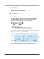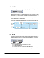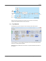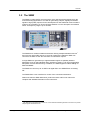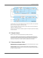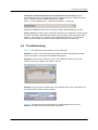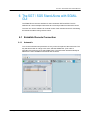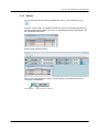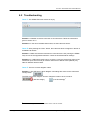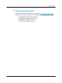
1
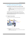
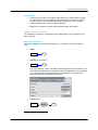
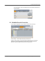
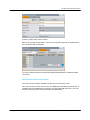
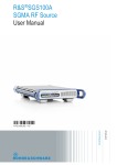
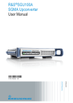
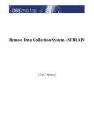
Connecting and Interfacing with SGMA Instruments Application Note Products: | R&SSMW200A | R&SSGS100A | R&SSGU100A | R&SSGT100A The SGMA products from Rohde & Schwarz are optimized for use in production and automated applications. Their key characteristics are high speed and a compact design. The instruments are also an ideal enhancement for the R&SSMW200A in MIMO applications. They can interface to the high-end vector signal generator and serve as additional RF outputs. C. Tröster-Schmid 10.2015-1GP103_1E Application Note This application note explains how to connect and interface with the SGMA instruments and gives some recommendations and hints about their use. It helps the user to get started and to understand how the instruments interact. Table of Contents Table of Contents 1GP103_1E 1 Introductory Note ................................................................... 3 2 Introduction ............................................................................ 3 3 Overview ................................................................................. 4 3.1 The SGMA Products .....................................................................................4 3.1.1 The SGS.........................................................................................................4 3.1.2 The SGU ........................................................................................................5 3.1.3 The SGT .........................................................................................................5 3.1.4 The SGMA-GUI ..............................................................................................6 3.2 The SMW .......................................................................................................7 4 The SGS-SGU Combination .................................................. 8 4.1 The SGU-Z4 Connection Kit ........................................................................8 4.2 Remote Control.............................................................................................9 4.3 Troubleshooting .........................................................................................10 4.4 Recommendations / Hints ...........................................................................9 5 The SMW with External RF Outputs ................................... 11 5.1 Physical Connections ................................................................................11 5.2 Establish Remote Connection ..................................................................13 5.3 Remote Control...........................................................................................15 5.4 Get an Overview .........................................................................................16 5.5 Delays between RF Outputs ......................................................................17 5.6 Troubleshooting .........................................................................................18 6 The SGT / SGS Stand-Alone with SGMA-GUI .................... 19 6.1 Establish Remote Connection ..................................................................19 6.1.1 Automatic ....................................................................................................19 6.1.2 Manual .........................................................................................................20 6.2 Troubleshooting .........................................................................................21 7 Ordering Information ........................................................... 22 Rohde & Schwarz Connecting and Interfacing with SGMA Instruments 2 Introductory Note 1 Introductory Note The following abbreviations are used in this application note for Rohde & Schwarz products: ® The R&S SMW200A vector signal generator is referred to as SMW. ® The R&S SGT100A SGMA vector RF source is referred to as SGT. ® The R&S SGS100A SGMA RF source is referred to as SGS. ® The R&S SGU100A SGMA upconverter is referred to as SGU. ® The R&S SGMA-GUI PC software is referred to as SGMA-GUI. ® ® ® The R&S SGU-Z4 connection kit R&S SGU100A to R&S SGS100A is referred to as SGU-Z4. 2 Introduction The SGMA products comprising the SGS, SGU and SGT are optimized for use in production and automated applications. Their key characteristics are high speed and a compact design. Though compact in size, the instruments have excellent RF characteristics (e.g. signal quality and level accuracy) and cover a wide frequency range up to microwave frequencies. The space-saving SGMA instruments are also an ideal enhancement for the SMW in MIMO applications with more than two RF test signals. They can interface to the SMW and serve as additional RF outputs. In this application the instruments are used to exploit the full capacity of the SMW’s powerful digital baseband section. This application note explains how to connect and interface with the SGMA instruments and gives some recommendations and hints about their use. This document is intended to help the user get started and understand how the instruments interact. For complete description and instructions please see the user manuals of the instruments. 1GP103_1E Rohde & Schwarz Connecting and Interfacing with SGMA Instruments 3 Overview 3 Overview This section gives a brief overview of the individual instruments covered by this application note and their key characteristics. 3.1 The SGMA Products 3.1.1 The SGS The SGS is an RF source designed to meet the requirements of automated test systems. It is available as a CW source or as a vector signal generator with an integrated I/Q modulator. Its frequency range is up to 12.75 GHz. The SGS can be controlled via the SGMA-GUI PC software (via USB, LAN or PCIe) the SMW (via USB or LAN) or remotely using SCPI commands (via USB, LAN or PCIe) Please note that the SGS has no integrated baseband generator. It requires external I/Q signals when operated as a vector signal generator. The following simplified block diagram illustrates the functional principle of the SGS. Please see also the SGS data sheet, product brochure and/or user manual for complete and detailed information on the instrument. 1GP103_1E Rohde & Schwarz Connecting and Interfacing with SGMA Instruments 4 Overview 3.1.2 The SGU The SGU is an upconverter extending the frequency range of the SGS up to 40 GHz. When connected properly (e.g. via the PCIe interface) the SGS recognizes the SGU automatically as an extension such the combined instruments act as a single unit. In this configuration, the SGU is controlled via the SGS. Please note that the SGU always requires an external synthesizer (the SGS is recommended). It cannot work stand-alone. The following simplified block diagram illustrates the functional principle of the SGU. Please see also the SGU data sheet, product brochure and/or user manual for complete and detailed information on the instrument. 3.1.3 The SGT The SGT is an RF vector signal generator with an integrated baseband generator. It has been optimized for use in production and automated applications. Its frequency range is up to 6 GHz. The SGT can be controlled via the SGMA-GUI PC software (via USB, LAN or PCIe) the SMW (via USB or LAN) or remotely using SCPI commands (via USB, LAN or PCIe) The following simplified block diagram illustrates the functional principle of the SGT. 1GP103_1E Rohde & Schwarz Connecting and Interfacing with SGMA Instruments 5 Overview Please see also the SGT data sheet, product brochure and/or user manual for complete and detailed information on the instrument. 3.1.4 The SGMA-GUI The SGMA-GUI is the user interface for the instruments SGS, SGU and SGT. The PC software can control multiple instruments at once and provides full instrument control (e.g. including firmware update). Please see also the SGMA-GUI user manual for complete and detailed information on the software. 1GP103_1E Rohde & Schwarz Connecting and Interfacing with SGMA Instruments 6 Overview 3.2 The SMW The SMW is a high-end RF and microwave vector signal generator designed for the most demanding applications. It is ideal for generating complex, digitally modulated signals of high quality required for the development of new wideband communications systems, the verification of 3G and 4G base stations or in the aerospace and defense sector. Its frequency range is up to 40 GHz. The SMW has a modular scalable architecture offering multiple baseband sources and up to two internal RF outputs. If more RF outputs are needed the SMW can connect to the SGS or SGT and use them as external RF outputs. 1 A single SMW can generate up to eight baseband signals to optimally address application such as multi-standard radio, interference testing, LTE carrier aggregation and phase coherent beamforming. In addition, the SMW supports realtime fading for SISO and MIMO. The SMW can connect up to six SGTs via digital I/Q or two SGSs/SGUs via analog I/Q. The SMW offers a user interface for control of the connected instruments. Please see also the SMW data sheet, product brochure and/or user manual for complete and detailed information on the instrument. 1 The SMW can be equipped with a maximum of two hardware baseband generators but these can provide multiple logical baseband sources. 1GP103_1E Rohde & Schwarz Connecting and Interfacing with SGMA Instruments 7 The SGS-SGU Combination 4 The SGS-SGU Combination The combination of SGS and SGU can generate vector modulated signals up to 40 GHz. To physically connect the instruments the option SGU-Z4 connection kit is recommended. 4.1 The SGU-Z4 Connection Kit The SGU-Z4 connection kit is a set of cables and mounting parts for connecting the SGS and the SGU. It includes the following cables (from SGS to SGU): Semi-rigid cable: RF out → LO in I/Q cables: I in → I out and Q in → Q out Trigger cable: TRIG in/out → TRIG in/out PCIe cable: PCIe → PCIe The following simplified block diagram illustrates the functional principle of the SGSSGU combination: 1GP103_1E Rohde & Schwarz Connecting and Interfacing with SGMA Instruments 8 The SGS-SGU Combination The I/Q signals from an external ARB generator are fed into the SGU. For frequencies below 12 GHz the I/Q signal is routed to the SGS. The RF output signal is taken from the SGU. The RF output covers the full frequency range from 10 MHz up to 40 GHz. If desired, an external reference frequency signal or LO signal for synthesizer coupling is fed into the SGS. 4.2 Remote Control Remote control of the combined instruments is possible via the SGS. The connection between the SGS and the SGU is established automatically via the PCIe interface. When connected, the SGS recognizes the SGU as an extension such that the combined instruments act as a single unit. This means, that only the SGS needs to be connected e.g. via LAN or USB to the SGMA-GUI or the SMW. 4.3 Recommendations / Hints Firmware version: Use the same firmware version for the SGS and the SGU. Use the same version also for the SGMA-GUI software. Firmware update: Currently, the SGU firmware update is only possible by directly interfacing the SGU. Disconnect the PCIe cable when performing a firmware update of the SGU to not affect the SGS. 1GP103_1E Rohde & Schwarz Connecting and Interfacing with SGMA Instruments 9 The SGS-SGU Combination Putting the combined instruments into operation for the first time: Run the internal adjustments on the SGU after having connected a SGU to a SGS for the first time. To do this, make the following steps on the SGS: Setup → Internal Adjustments → Adjust only extension → Adjust All Repeat this adjustment whenever you (re)connected a SGU physically to a SGS. Power cycling: To switch off the combined instruments, it is sufficient to switch off just the SGS. The SGU is automatically switched off by the SGS. Both instruments are on standby. In the same way, to switch on the combined instruments, it is sufficient to switch on just the SGS. The SGU is automatically switched on by the SGS. 4.4 Troubleshooting Issue 1: The SGS does not recognize the connected SGU. Solution 1: Power on the instruments direct after each other starting with the SGS. This way the PCIe connection will be established properly. Solution 2: Check in the “Extension” menu of the SGS if the SGU is set to “ON”. Perform a scan, if the SGU is not shown in the list. Solution 3, only if all other solutions fail: In the “Maintenance” menu of the SGS, set the PCIe interface mode to “Root Complex”. Issue 2: The SGS does not accept frequency settings higher than 12.5 GHz. Reason: The SGU has not been detected. See issue 1. 1GP103_1E Rohde & Schwarz Connecting and Interfacing with SGMA Instruments 10 The SMW with External RF Outputs 5 The SMW with External RF Outputs The SMW offers up to two internal RF outputs. If more RF outputs are needed, external instruments such as the SGT or SGS can be connected to the SMW. The SGS connects to the analog I/Q outputs of the SMW for frequencies up to 12.75 GHz. The SGS-SGU combination connects to the analog I/Q outputs of the SMW for frequencies up to 40 GHz. The SGT connects to the digital I/Q outputs of the SMW for frequencies up to 6 GHz. The SMW offers up to two analog I/Q outputs and up to six digital I/Q outputs. The external instruments can be connected via USB or LAN. The user can control them directly via the SMW touchscreen. Basic settings such as RF parameters are automatically transferred to the connected instrument via the USB/LAN control line. As a result, the whole setup acts like one unit. 5.1 Physical Connections An example setup with two external RF outputs looks as follows: RF outputs C D REF OUT REF IN REF IN I/Q USB I/Q USB I/Q signal 10 MHz reference frequency Control (USB / LAN) REF OUT RF outputs A B Per external instrument there are three connections needed: I/Q signal 10 MHz reference frequency for frequency synchronization of the synthesizers Control line, either via USB or LAN 1GP103_1E Rohde & Schwarz Connecting and Interfacing with SGMA Instruments 11 The SMW with External RF Outputs I/Q connection Analog I/Q connection: Use cables of the same type, exactly equal in length. This is important, since otherwise a delay between the I and the Q signal is introduced, which can degrade signal quality significantly. Also, use high quality adapters and do not accumulate adapters. ® Digital I/Q connection: Use the cable R&S SMU-Z6 (LVDS cable). 10 MHz reference connection It is mandatory to share the 10 MHz reference signal between the instruments. Use daisy-chaining. USB / LAN connection Connect the SMW to the external instrument (e.g. an SGS) in one of the following ways: USB: SMW SGS 2 LAN Direct connection : SMW SGS Use “Auto (DHCP)” mode: The SMW selects automatically an IP address. The SGS selects automatically an IP address, too. Both addresses are compatible. To connect more external instruments, use a LAN switch. All instruments select automatically compatible IP addresses. LAN Network: SMW 2 1GP103_1E Network SGS No crossover LAN cable is needed. Rohde & Schwarz Connecting and Interfacing with SGMA Instruments 12 The SMW with External RF Outputs Use “Auto (DHCP)” mode: All IP addresses are automatically assigned by the network (DHCP). rssmw200a100949 5.2 Establish Remote Connection In the “System Configuration” menu, select the “External RF and I/Q” tab. Touch “Config…” for the output connector you want to use. Press the “Scan” button to scan the LAN and the USB interfaces for connected instruments. The found instruments are listed under the “External Instrument” parameter. Select the target instrument from the drop down list. 1GP103_1E Rohde & Schwarz Connecting and Interfacing with SGMA Instruments 13 The SMW with External RF Outputs Press the “Apply and Connect” button. Back in the “System Configuration” menu, the connected instrument is displayed and the connection state is indicated. To connect further instruments repeat the steps described above for different output connectors. Auto Connect Feature (only for SGT) The “Auto Connect” feature simplifies the process of connecting a SGT. If the "Auto Connect" check box is active, the SMW will automatically detect a SGT at its digital output and establish the connection via the USB/LAN control line. The user does not need to perform the manual steps described above. 1GP103_1E Rohde & Schwarz Connecting and Interfacing with SGMA Instruments 14 The SMW with External RF Outputs 5.3 Remote Control Remote control is supported for the following configurations: SGT connected to digital output of SMW SGS connected to analog output of SMW If an external instrument is connected, the SMW automatically sets the following parameters and triggers the following actions over the control line: Preset RF frequency RF level Crest factor of I/Q signal External 10 MHz reference oscillator RF output state → on/off I/Q modulator state → on Digital I/Q input state → on (only on SGT) Digital I/Q input sample rate (only on SGT) Baseband clock → sync mode “Dig I/Q In” (only on SGT; the SGT gets the baseband clock and trigger from the SMW via the digital connection) If an external instrument is connected, the SMW automatically activates its own analog or digital output to ensure signal flow. Specific settings can be made via the SMW GUI in three different ways: 1) By using a user-defined initialization sequence, i.e. a set of SCPI commands. The initialization sequence is automatically transmitted to the external instrument during the connection process. 2) During operation, the user can control basic RF settings of the external instruments via the “System Configuration” menu. 3) During operation, the user can send a remote SCPI command or a SCPI command sequence (file) to the external instrument. 1GP103_1E Rohde & Schwarz Connecting and Interfacing with SGMA Instruments 15 The SMW with External RF Outputs 5.4 Get an Overview The external instruments are shown in the overview diagram. The graphical elements of the diagram are hotkeys and lead to the corresponding configuration menus. The diagram shows the input and output connectors of the SMW. For each output connector it shows which I/Q stream is output (e.g. stream A) if the output is active or inactive → a solid line indicates an active output if an external instrument is connected and which one→ blue color means the RF output of the external instrument is active; the connection state is indicated separately 1GP103_1E Rohde & Schwarz Connecting and Interfacing with SGMA Instruments 16 The SMW with External RF Outputs 5.5 Delays between RF Outputs There is only a very small delay of a few nanoseconds between the internal RF outputs of the SMW and the external RF outputs from the SGT or SGS. The following example shows three RF signals from the SMW, SGS and SGT on an oscilloscope. The horizontal resolution is 50 ns/div. SGS RF The user has the possibility to cancel any small delay by applying an intended delay to the baseband signals using the SMW’s digital impairments feature. The “I/Q Delay” parameter delays the baseband signal with picosecond resolution. By adjusting this parameter the RF output signals can be perfectly aligned in time, if required for the application. Note: On the SMW, the “I/Q Delay” parameter for the digital I/Q outputs can only be set if a SGT is connected. Otherwise this parameter is greyed out. 1GP103_1E Rohde & Schwarz Connecting and Interfacing with SGMA Instruments 17 The SMW with External RF Outputs 5.6 Troubleshooting Issue 1: The RF outputs are delayed relative to each other. Solution 1: Make sure that the basebands of the SMW are all synchronized. Check the trigger settings. Issue a trigger event. Solution 2: Compensate small delays using the “I/Q Delay” parameter (see section 5.5). Note: Large delays (microsecond range) are due to some failure. Check baseband synchronization in this case (solution 1). Issue 2: There is no RF signal output from the external RF instrument. Solution 1: Check on the SMW (“External RF and I/Q” tab) if the RF output of the external instrument is turned on (”RF State” parameter). Solution 2: Check on the SMW (“I/Q Stream Mapper” tab) if there is a stream routed to the wanted output. Check if the baseband generator associated with this stream is turned on and in “running” state. Issue 3: The “REF EXT” LED on the front panel of the connected instrument is off, although the instrument is connected and an external reference signal is fed to the instrument. Solution 1: Configure the instrument to use the external reference signal. Send the following SCPI commands via the “Remote Control” tab. Check if the “REF EXT” LED on the front panel of the instrument is green. 1GP103_1E Rohde & Schwarz Connecting and Interfacing with SGMA Instruments 18 The SGT / SGS Stand-Alone with SGMA-GUI 6 The SGT / SGS Stand-Alone with SGMAGUI The SGMA-GUI is the user interface for the instruments SGT and SGS. The PC software can control multiple instruments at once and provides full instrument control. The user can use the software for manual control of the instruments and for monitoring the instrument status during remote control. 6.1 Establish Remote Connection 6.1.1 Automatic Turn on the instrument and press the “ID” key on the front panel of the instrument. The key will start to blink in orange color. Now, start the SGMA-GUI. (The order is important: first press key, then start SGMA-GUI.) The instrument will automatically be added to the list of available instruments and set active. 1GP103_1E Rohde & Schwarz Connecting and Interfacing with SGMA Instruments 19 The SGT / SGS Stand-Alone with SGMA-GUI 6.1.2 Manual Turn on the instrument and start the SGMA-GUI. Click on the “Instruments” icon. Press the “Scan” button. The SGMA-GUI will now scan for connected instruments on all supported interfaces (USB, LAN, PCIe). The detected instrument will appear in the list of available instruments. Set the target instrument active. Check if the status indicator is green. A green indicator confirms that the remote connection is established. Status indicator 1GP103_1E Max. RF frequency indicator Rohde & Schwarz Connecting and Interfacing with SGMA Instruments 20 The SGT / SGS Stand-Alone with SGMA-GUI 6.2 Troubleshooting Issue 1: The SGMA-GUI main window is empty. Solution 1: Establish a remote connection to an instrument. Follow the instructions given in section 6.1.2. Solution 2: In the list of available instruments, set the instrument active. Issue 2: After pressing the “Scan” button, the instrument does not appear in the list of available instruments. Solution 1: Make sure that the instrument is connected to the PC (running the SGMAGUI) via one of the supported interfaces. Check the interface/network settings. Solution 2: In LANs with a DHCP server, press the “LAN” key at the front panel of the instrument (for a few seconds) to reset the instrument to DHCP mode (default). Any static IP address will be erased. Issue 3: There is no block diagram visible. Solution 1: The SGS has no block diagram. All settings are done via the “Instrument Config” button: The SGT has a block diagram. Use the “Diagram” button to show or hide it: (old GUI design) 3 1GP103_1E (new GUI design) 3 The new GUI design is available from software version 3.20.xxx onwards. Rohde & Schwarz Connecting and Interfacing with SGMA Instruments 21 Ordering Information 7 Ordering Information Please visit the Rohde & Schwarz product websites at www.rohde-schwarz.com for comprehensive ordering information on the following Rohde & Schwarz instruments: 1GP103_1E ® R&S SMW200A vector signal generator ® R&S SGT100A SGMA vector RF source ® R&S SGS100A SGMA RF source ® R&S SGU100A SGMA upconverter Rohde & Schwarz Connecting and Interfacing with SGMA Instruments 22 About Rohde & Schwarz Rohde & Schwarz is an independent group of companies specializing in electronics. It is a leading supplier of solutions in the fields of test and measurement, broadcasting, radiomonitoring and radiolocation, as well as secure communications. Established more than 75 years ago, Rohde & Schwarz has a global presence and a dedicated service network in over 70 countries. Company headquarters are in Munich, Germany. Environmental commitment ● Energy-efficient products ● Continuous improvement in environmental sustainability ● ISO 14001-certified environmental management system Regional contact Europe, Africa, Middle East +49 89 4129 12345 [email protected] North America 1-888-TEST-RSA (1-888-837-8772) [email protected] Latin America +1-410-910-7988 [email protected] Asia/Pacific +65 65 13 04 88 [email protected] China +86-800-810-8228 /+86-400-650-5896 [email protected] This application note and the supplied programs may only be used subject to the conditions of use set forth in the download area of the Rohde & Schwarz website. R&S® is a registered trademark of Rohde & Schwarz GmbH & Co. KG; Trade names are trademarks of the owners. Rohde & Schwarz GmbH & Co. KG Mühldorfstraße 15 | D - 81671 München Phone + 49 89 4129 - 0 | Fax + 49 89 4129 – 13777 www.rohde-schwarz.com