1
Fillcontrol Plus
GB
Operating manual
Original operating manual
2014-10-15
Contents
English
Fillcontrol Plus
2014-10-15
Contents
1
Notes on the operating manual .................................................................................................................................. 5
2
Liability and guarantee ................................................................................................................................................ 5
3
Safety ............................................................................................................................................................................ 6
3.1
3.2
3.3
3.4
3.5
3.6
4
Explanation of symbols ...................................................................................................................................................... 6
3.1.1
Symbols and notes used .................................................................................................................................. 6
3.1.2
Safety symbols used ......................................................................................................................................... 6
Personnel requirements ..................................................................................................................................................... 7
Personal protective equipment ........................................................................................................................................... 7
Intended use....................................................................................................................................................................... 7
Inadmissible operating conditions ...................................................................................................................................... 7
Residual risks ..................................................................................................................................................................... 8
Description of the device ............................................................................................................................................ 9
4.1
4.2
4.3
4.4
4.5
4.6
Description ......................................................................................................................................................................... 9
Overview ............................................................................................................................................................................ 9
Identification ..................................................................................................................................................................... 10
4.3.1
Nameplate ...................................................................................................................................................... 10
4.3.2
Type code ....................................................................................................................................................... 10
Function............................................................................................................................................................................ 11
Scope of delivery .............................................................................................................................................................. 12
Optional equipment and accessories ............................................................................................................................... 12
5
Technical data ............................................................................................................................................................ 13
6
Installation .................................................................................................................................................................. 14
6.1
6.2
6.3
6.4
6.5
6.6
7
Commissioning .......................................................................................................................................................... 25
7.1
7.2
7.3
7.4
7.5
7.6
7.7
7.8
8
Installation conditions ....................................................................................................................................................... 14
6.1.1
Incoming inspection ........................................................................................................................................ 14
Preparatory work .............................................................................................................................................................. 15
Execution.......................................................................................................................................................................... 15
6.3.1
Wall mounting ................................................................................................................................................. 16
6.3.2
Hydraulic connection ...................................................................................................................................... 17
Switching and make-up variants ...................................................................................................................................... 18
Electrical connection ........................................................................................................................................................ 20
6.5.1
Terminal diagram ............................................................................................................................................ 21
6.5.2
RS-485 interface ............................................................................................................................................. 23
Installation and commissioning certificate ........................................................................................................................ 24
Checking the requirements for commissioning ................................................................................................................ 25
Determining the P0 minimum operating pressure for the controller.................................................................................. 25
Filling the device with water ............................................................................................................................................. 26
Operator panel ................................................................................................................................................................. 26
Parametrising the controller in the Customer menu ......................................................................................................... 27
Function test ..................................................................................................................................................................... 27
Filling system with device ................................................................................................................................................. 28
Starting Automatic mode .................................................................................................................................................. 28
Operation .................................................................................................................................................................... 29
8.1
Operating modes .............................................................................................................................................................. 29
8.1.1
Automatic mode .............................................................................................................................................. 29
8.1.2
Manual mode .................................................................................................................................................. 29
8.1.3
Stop mode ...................................................................................................................................................... 30
Fillcontrol Plus — 2014-10-15
English — 3
Contents
8.1.4
9
Controller ................................................................................................................................................................... 31
9.1
9.2
10
Summer operation...........................................................................................................................................30
Configuring settings in the controller ................................................................................................................................31
9.1.1
Customer menu...............................................................................................................................................31
9.1.2
Service menu ..................................................................................................................................................35
9.1.3
Default settings ...............................................................................................................................................35
Messages .........................................................................................................................................................................36
Maintenance ............................................................................................................................................................... 38
10.1
10.2
10.3
Maintenance schedule......................................................................................................................................................39
Exterior leak test ...............................................................................................................................................................39
Maintenance certificate.....................................................................................................................................................40
11
Disassembly .............................................................................................................................................................. 41
12
Annex ......................................................................................................................................................................... 42
12.1
12.2
12.3
12.4
4 — English
Reflex Customer Service ..................................................................................................................................................42
Conformity and standards ................................................................................................................................................43
Guarantee.........................................................................................................................................................................44
Glossary ...........................................................................................................................................................................44
Fillcontrol Plus — 2014-10-15
Notes on the operating manual
1
Notes on the operating manual
This operating manual is an important aid for ensuring the safe and reliable functioning of the device.
The operating manual will help you to:
• avoid any risks to personnel.
• become acquainted with the device.
• achieve optimal functioning.
• identify and rectify faults in good time.
• avoid any faults due to improper operation.
• cut down on repair costs and reduce the number of downtimes.
• improve the reliability and increase the service life of the device.
• avoid causing harm to the environment.
Reflex Winkelmann GmbH accepts no liability for any damage resulting from failure to observe the information in this operating manual.
In addition to the requirements set out in this operating manual, national statutory regulations and provisions in the country of installation
must also be complied with (concerning accident prevention, environment protection, safe and professional work practices, etc.).
This operating manual describes the device with basic equipment and interfaces for optional equipment with additional functions. For
optional equipment and accessories, see chapter 4.6 "Optional equipment and accessories" on page 12 ..
Notice!
Every person installing this equipment or performing any other work at the equipment is required to carefully read this
operating manual prior to commencing work and to comply with its instructions. The manual is to be provided to the
device operator and must be stored near the device for access at any time.
2
Liability and guarantee
The device has been designed using state-of-the-art technology and in accordance with generally recognised technical safety
regulations. Nevertheless, its use can pose a risk to life and limb of personnel or third persons as well as cause damage to the system or
other property.
It is not permitted to make any modifications at the device, such as to the hydraulic system or the circuitry.
Warranty and liability claims will not be accepted by the manufacturer if these can be traced back to one or more of the following causes:
• Improper use of the device.
• Improper start-up, operation, maintenance, servicing, repair or installation of the device.
• Failure to observe the safety information in this operating manual.
• Operation of the device with defective or improperly installed safety/protective equipment.
• Failure to perform maintenance and inspection work according to schedule.
• Use of unapproved spare parts and accessories.
The proper installation and start-up of the device is a prerequisite for the making of warranty claims.
Note!
Have the Reflex Customer Service carry out commissioning and the annual maintenance, see chapter 12.1 "Reflex
Customer Service" on page 42 .
Fillcontrol Plus — 2014-10-15
English — 5
Safety
3
Safety
3.1
Explanation of symbols
3.1.1
Symbols and notes used
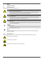
The following symbols are used in this operating manual.
Danger
•
Danger to life and/or severe damage to health
– The corresponding warning symbol in combination with the "Danger" signal term indicates an imminent
threatening danger which will result in death or severe (irreversible) injuries.
Warning
•
Severe damage to health
– The corresponding warning symbol in combination with the "Warning" signal term indicates a threatening
danger which may result in death or severe (irreversible) injuries.
Caution
•
Damage to health
– The corresponding warning symbol in combination with the "Caution" signal term indicates a danger which may
result in minor (reversible) injuries.
Attention!
•
Damage to property
– This symbol in combination with the "Attention" signal word indicates a situation that may cause damage to the
product itself or objects in its vicinity.
Notice!
This symbol in combination with the "Notice" signal word indicates useful tips and recommendations regarding the
efficient use of the product.
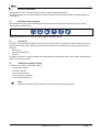
3.1.2
Safety symbols used
The following safety symbols are used in this operating manual. They are also attached to the equipment or in its vicinity.
This symbol warns of electric.voltage.
This symbol warns of a hot surface.
This symbol warns of overpressure in conduits and connections.
6 — English
Fillcontrol Plus — 2014-10-15
Safety
3.2
Personnel requirements
Only specialist personnel or specifically trained personnel may install and operate the equipment.
The electric connections and the wiring of the device must be executed by a specialist in accordance with all applicable national and
local regulations.
3.3
Personal protective equipment
When working at the system, wear the stipulated personal equipment such as hearing and eye protection, safety boots, helmet,
protective clothing, protective gloves.
See the national regulation of your country for personal protective equipment required.
3.4
Intended use
The device is a pressure maintaining station for heating and cooling water systems. It is intended to maintain the water pressure and to
add water within a facility system. The devices may be used only in systems that are sealed against corrosion and with the following
water types:
• Non-corrosive
• Chemically non-aggressive
• Non-toxic
The ingress of atmospheric oxygen by permeation into the entire heating and cooling water system, make-up water and similar must be
reliably minimised during operation.
3.5
Inadmissible operating conditions
The devices are not suited for the following conditions.
• In mobile system operation.
• For outdoors operation.
• For the use with mineral oils.
• For the use with flammable media.
• For the use with distilled water.
Notice!
Changes to the hydraulic system or interference with the interconnection are strictly prohibited.
Fillcontrol Plus — 2014-10-15
English — 7
Safety
3.6
Residual risks
This device has been manufactured to the current state of the art. However, some residual risk cannot be excluded.
Warning – large weight!
•
The devices are very heavy. Thus, there is a risk of physical damage and accidents.
– Use only lifting gear suitable for transport and installation.
Caution – risk of burning!
•
Excessively hot surfaces in heating systems can cause burns on the skin.
– Wear protective gloves.
– Please place appropriate warning signs in the vicinity of the device.
Caution – risk of injury!
•
8 — English
If installation, removal or maintenance work is not carried out correctly, there is a risk of burns and other injuries at
the connection points, if pressurised hot water or hot steam suddenly escapes.
– Ensure proper installation, removal or maintenance work.
– Ensure that the system is de-pressurised before performing installation, removal or maintenance work at the
connection points.
Fillcontrol Plus — 2014-10-15
Description of the device
4
Description of the device
4.1
Description
The device is a make-up station for heating and cooling water systems without pump. The device controller regulates the make-up with
water for the facility system.
The device is designed for two make-up systems:
• Adding fresh water to facility systems with a diaphragm expansion tank.
• Adding fresh water to facility systems with pressure maintaining station.
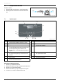
4.2
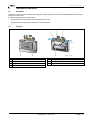
Overview
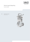
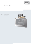
1
2
3
WC
WC
6
1
2
3
4
"BV" shut-off valve
"PIS" pressure transducer
"WV" make-up valve
Console for wall mounting
5
4
5
6
WC
000191_001_R001
Cover (hinged)
Control Basic controller
Fresh water inlet/outlet
Fillcontrol Plus — 2014-10-15
English — 9
Description of the device
4.3
Identification
4.3.1
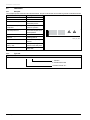
Nameplate
The nameplate provides information about the manufacturer, the year of manufacture, the manufacturing number and the technical data.
Information on nameplate
Type
Serial No.
min. / max. allowable pressure P
Meaning
Device name
Serial number
Minimum/maximum
permissible pressure
max. continuous operating
Maximum temperature for
temperature
continuous operation
min. / max. allowable temperature Minimum/maximum
/ flow temperature TS
permissible temperature/TS
flow temperature
Year built
Year of manufacture
min. operating pressure set up on Factory-set minimum
shop floor
operating pressure
at site
Set minimum operating
pressure
max. pressure saftey valve
Factory-set opening
factory - aline
pressure of the safety valve
at site
Set opening pressure of the
safety valve
4.3.2
000043_001_R001
Type code
Type code
Fillcontrol Plus P
1,4
E
– : Standard
E : Stainless steel model
Volumetric flow rate "Kvs"
10 — English
Fillcontrol Plus — 2014-10-15
Description of the device
4.4
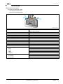
Function
LIS
PIS
WC
ST
1
BP
DC
WC
2
3
000192_001_R001
1
Fillset Impuls, see chapter 4.6 "Optional equipment and
accessories" on page 12 .
PIS
2
"Fillsoft" softening system, see chapter 4.6 "Optional
equipment and accessories" on page 12 .
WC
Pressure transducer for pressure-dependent make-up
• Internal signal line from the pressure transducer to
the controller
Make-up line to the device
3
LIS
Fillcontrol Plus
Filling level monitoring for level-dependent make-up
• External signal line to the controller
DC
Make-up line to the system
Fillcontrol Plus controls the make-up with fresh water for the facility system.
The controller monitors the following functions:
• Make-up time.
• Make-up cycles.
• Make-up quantity, if an optional contact water meter is installed.
The controller will detect small leaks in the system. When a leak is detected, the controller interrupts the make-up with as soon as the
make-up time or the make-up cycles are exceeded.
Fillcontrol Plus supports two make-up variants:
• Pressure-dependent make-up with water in a facility system with a diaphragm expansion tank ("Magcontrol" mode).
– The pressure transducer sends a signal to the controller if the pressure drops below the minimum working pressure of the
facility system. The make-up is released. Fresh water is added to the facility system. For calculating the filling pressure into the
facility system, see chapter 7.2 "Determining the P0 minimum operating pressure for the controller" on page 25 .
• Level-dependent make-up with water in a facility system with a pressure-maintaining station ("Levelcontrol" mode).
– A pressure-maintaining station monitors the filling level in the expansion tank. If the level drops below minimum, the pressuremaintaining station sends a signal to the controller. The make-up is released. Fresh water is added to the facility system.
The mode is set in the Customer menu, see chapter 9.1.1 "Customer menu" on page 31 .
The controller may monitor additional function, if you combine various accessories.
The following components are available as optional accessories:
• "Reflex Fillsoft" softening system.
• "Reflex Fillset" with "FQI" water meter.
• "Reflex Fillset Imuls" with "FQIRA+" contact water meter.
Note!
For optional accessories, see chapter 4.6 "Optional equipment and accessories" on page 12 .
Fillcontrol Plus — 2014-10-15
English — 11
Description of the device
4.5
Scope of delivery
The scope of delivery is described in the shipping document and the content is shown on the packaging.
Proceed as follows:
1. Immediately after receipt of the goods, please check the shipment for completeness and damage.
2. Please notify us immediately of any transport damage.
Basic make-up equipment:
• The pre-wired device.
• Operating manual.
4.6
Optional equipment and accessories
The following optional equipment and expansion functions are available for this device:
• Fillset or Fillset Compact as add-on modules for drinking water systems.
• Softening with Reflex Fillsoft.
• Expansions for Reflex Basic controllers:
– I/O modules
– Bus modules:
• Lonworks Digital
• Lonworks
• Profibus DP
• Ethernet
Note!
Separate operating instructions are supplied with accessories.
12 — English
Fillcontrol Plus — 2014-10-15
Technical data
5
Technical data
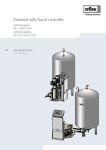
Make-up station with controller.
• For heating and cooling water systems:
– With diaphragm expansion tanks.
– With pressure-maintaining stations.
WC
WC
000193_001_R001
Type, Article No.
Width
Height
Depth
Weight
Permissible gauge operating pressure
Permissible operating temperature
Permissible ambient temperature
Volumetric flow rate Kvs
Inlet pressure to "Fillcontrol Plus“
Make-up pressure to the system
Degree of protection IP
Electrical power supply
• Output
• Fusing
• Voltage
• Frequency
Connector for make-up line, internal thread (IG)
• To the device
• To the system
Fillcontrol Plus / 8812100
Fillcontrol Plus E / 8812200
340 mm
320 mm
190 mm
2.5 kg
10 bar
90 °C
> 0 °C – 45 °C
1,4 m3/h
≤ 6 bar (if higher, install a pressure reducer)
≤ ?? bar
IP 54
350 W
4A
230 V
50 Hz
G 3/4 "
G 1/2 "
Fillcontrol Plus — 2014-10-15
English — 13
Installation
6
Installation
Danger – electric shock!
•
Risk of serious injury or death due to electric shock.
– Ensure that the system is voltage-free before installing the device.
– Ensure that the system is secured and cannot be reactivated by other persons.
– Ensure that installation work for the electric connection of the device is carried out by an electrician, and in
compliance with electrical engineering regulations.
Caution – risk of injury!
•
If installation, removal or maintenance work is not carried out correctly, there is a risk of burns and other injuries at
the connection points, if pressurised hot water or hot steam suddenly escapes.
– Ensure proper installation, removal or maintenance work.
– Ensure that the system is de-pressurised before performing installation, removal or maintenance work at the
connection points.
Caution – risk of burning!
•
Excessively hot surfaces in heating systems can cause burns on the skin.
– Wear protective gloves.
– Please place appropriate warning signs in the vicinity of the device.
Caution – Risk of injury due to falls or bumps!
•
Bruising from falls or bumps at system components during installation.
– Wear personal protective equipment (helmet, protective clothing, gloves, safety boots).
6.1
Installation conditions
6.1.1
Incoming inspection
Prior to shipping, this device was carefully inspected and packed. Damages during transport cannot be excluded.
Proceed as follows:
1. Upon receipt of the goods, check the shipment for
• completeness and
• possible transport damage.
2. Document any damage.
3. Contact the forwarding agent to register a complaint accordingly.
14 — English
Fillcontrol Plus — 2014-10-15
Installation
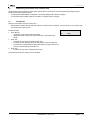
6.2
Preparatory work
max.45 °C
min.0 °C
≥ DN 15
000037_001_R001
Conditions for device installation:
• Frost-free, well-ventilated room.
– Room temperature range: 0 °C to 45 °C.
• Filling connection.
– If necessary, provide a DN 15 filling connection according to DIN 1988 T 4.
• Electric connection: 230 V~, 50 Hz, 16 A with upstream ELCB: Tripping current 0.03 A.
6.3
Execution
Attention! – Damage due to improper installation
Bear in mind that the device may be subject to additional stresses through the connection of piping or system equipment.
• Ensure that pipes are connected from the device to the system without stresses being induced.
• If necessary, provide support structures for the pipes or devices.
The device may be installed anywhere within the system if it operated within the permissible pressure and temperature ranges, see
chapter 5 "Technical data" on page 13 .
In systems with a diaphragm expansion tank, the device must be installed in the vicinity of the tank to ensure that the filling pressure for
the fresh water make-up is recorded by the "PIS" pressure transducer in the device. For calculating the filling pressure, see chapter 7.2
"Determining the P0 minimum operating pressure for the controller" on page 25 .
Proceed as follows for the installation:
1. Position the device.
2. Create the water-side connections of the device to the system.
3. Create the interfaces according to the terminal plan.
Fillcontrol Plus — 2014-10-15
English — 15
Installation
6.3.1
Wall mounting
The device is installed at the wall. Bore holes for wall mounting
are provided on the rear of the console (1) housing.
Select the attachment means according to the wall properties
and the weight (G) of the device.
During installation, ensure that:
• The device is installed sufficiently close to the diaphragm
expansion tank. You ensure so that the "PIS" pressure
sensor is able to measure the filling pressure.
• The fixtures can be operated.
•
The feed connections of the pipes are not adversely
affected.
16 — English
Fillcontrol Plus — 2014-10-15
1
G
000194_001_R001
Installation
6.3.2
Hydraulic connection
Attention! – Damage due to improper installation
Bear in mind that the device may be subject to additional stresses through the connection of piping or system equipment.
• Ensure that pipes are connected from the device to the system without stresses being induced.
• If necessary, provide support structures for the pipes or devices.
DN
WC
ST
1
1
2
3
4
BP
WC
2
DC
3
Fillset Impuls
"Fillsoft" softening system
"WV" Make-up valve
Fillcontrol Plus
4
5
WC
DC
DN
5
000195_001_R001
"BV" shut-off device
Make-up line to the device
Make-up line to the system
Nominal diameter of the make-up line
Prepare the connection as follows:
1. Select the "DN" nominal diameter for the make-up lines.
– At a length of up to 10 metres: DN 15.
– At a length of more than 10 metres: DN 20.
2. Connect the "DC" make-up line to the "BV"shut-off device.
3. Connect the "DC" make-up line to the system.
4. Connect the "WC" make-up line to the "WV" make-up valve.
5. Connect the "WC" make-up line to the external fresh water system.
The make-up lines are connected.
Note!
Use a pressure reducer in the "WC" make-up line if the fresh water system pressure exceeds 6 bar.
Note!
For selecting the make-up variants, see chapter 6.4 "Switching and make-up variants" on page 18 .
Fillcontrol Plus — 2014-10-15
English — 17
Installation
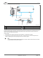
6.4
Switching and make-up variants
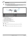
Example of a pressure-dependent make-up with "Fillcontrol Plus".
DN
PIS
ST
WC
1
1
2
3
Fillset
Fillcontrol Plus
Diaphragm expansion tank MAG
BP
2
3
PIS
WC
DC
000196_001_R001
Pressure transducer
Make-up line to the device
Nominal diameter of the make-up line
In facility systems with a diaphragm expansion tank, the "PIS" pressure transducer in the device monitors the make-up with fresh water.
When the required filling pressure for water make-up drops below the minimum value, the pressure transducer sends a signal to the
device controller. The make-up is released. Fresh water is added to the facility system.
Proceed as follows:
1. In the Customer menu, activate the "Magcontrol" mode, see chapter 9.1.1 "Customer menu" on page 31 .
2. Connect the pressure line near the connection to the diaphragm expansion tank.
– This ensures that the "PIS" pressure transducer detects the filling pressure required for the make-up with fresh water.
– For calculating the filling pressure, see chapter 7.2 "Determining the P0 minimum operating pressure for the controller" on page
25 .
3. Do not use nominal diameters below the specified diameters for the "WC"make-up lines.
– You will avoid an undesired cycling of the make-up.
18 — English
Fillcontrol Plus — 2014-10-15
Installation
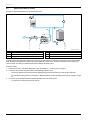
Example of a level-dependent make-up with "Fillcontrol Plus".
4
LIS
DN
230V
PIS
WC
ST
1
1
2
3
Fillset Impuls
"Fillsoft" softening system
Fillcontrol Plus
BP
2
3
4
WC
DN
000197_001_R001
"Reflexomat" pressure maintaining station
Make-up line to the device
Nominal diameter of the make-up line
The pressure maintaining station is fitted with a monitoring device for the filling level in the expansion tank. If the filling level drops below
the minimum level in the expansion tank, the pressure maintaining station sends a signal to the device controller. The make-up is
released. Fresh water is added to the facility system.
Proceed as follows:
1. In the Customer menu, activate the "Levelcontrol" mode, see chapter 9.1.1 "Customer menu" on page 31 .
2. The filling pressure for make-up with fresh water must be at least 1.7 bar higher than the "P0" minimum working pressure, see
chapter 7.2 "Determining the P0 minimum operating pressure for the controller" on page 25 .
Note!
You may combine the device with softening systems (Fillsoft, for example); available as optional accessories, see chapter
4.6 "Optional equipment and accessories" on page 12 .
Fillcontrol Plus — 2014-10-15
English — 19
Installation
6.5
Electrical connection
Danger – electric shock!
•
Risk of serious injury or death due to electric shock.
– Ensure that the system is voltage-free before installing the device.
– Ensure that the system is secured and cannot be reactivated by other persons.
– Ensure that installation work for the electric connection of the device is carried out by an electrician, and in
compliance with electrical engineering regulations.
Danger – electric shock!
•
Risk of serious injury or death due to electric shock. Some parts of the main board may still carry 230V voltage even
with the device physically isolated from the 230 V power supply.
– Before you remove the covers, completely isolate the device controller from the power supply.
The following descriptions apply to standard systems and are limited to the necessary user-provided connections.
1. Disconnect the system from the power source and secure it against unintentional reactivation.
2. Remove the cover.
3. Install a screwed cable gland suitable for the respective cable. M16 or M20, for example.
4. Thread all cables to be connected through the cable gland.
5. Connect all cables as shown in the terminal diagram, see chapter 6.5.1 "Terminal diagram" on page 21 .
– Note that the fusing for the device connection is to be provided by the user, see chapter 5 "Technical data" on page 13 .
6. Install the cover.
7. Connect the mains plug to the 230 V power supply.
8. Activate the system.
The electrical connection is completed.
20 — English
Fillcontrol Plus — 2014-10-15
Installation
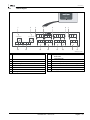
6.5.1
Terminal diagram
Error
Auto
Quit
Menu
1
2
3
7
T 0,315 A
T 0,315 A
8
Y2
9
N
PE
PE
2
N
15
3
L
4
PE
5
N
6
19 20 21 25 26
13 14 15
COM
NC
6
NO
Manual
Stop
7
29 30 31
A(+)
GND
RS-485
B(+)
RS-485
10 11 12
1
5
4
Ok
Auto
Y1
N
PE
16 17 18
22 23 24 27 28
GND
+24V
32 33 34
+24V
WZ
WM
M1
14
13
12
11
10
9
8
000090_001_R001
1
"L" fuse for electronics and solenoid valves
9
2
3
4
5
6
7
8
"N" fuse for solenoid valves
Solenoid valve (not for motor ball valve)
Group message
Not used
Not used
RS-485 interface
Shielding
10
11
12
13
14
15
Digital inputs
• Water meter
• Insufficient water
Not used
Pressure analogue input
External make-up demand ("Levelcontrol" only)
Not used
Not used
Mains supply
Fillcontrol Plus — 2014-10-15
English — 21
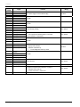
Installation
Terminal
number
1
2
3
4
5
6
10
11
12
13
14
15
16
17
18
19
20
21
PE
N
L
PE
N
M1
Y1
N
PE
COM
NC
NO
Not assigned
Make-up (230 V)
Make-up (230 V)
PE shield
- Level (signal)
+ Level (+ 18 V)
22
23
24
PE (shield)
- Pressure (signal)
+ Pressure (+ 18 V)
25
0 – 10 V (correcting
variable)
0 – 10 V (feedback)
GND
+ 24 V (supply)
A
B
GND
+ 24 V (supply)
E1
26
27
28
29
30
31
32
33
34
22 — English
Signal
E2
Function
230 V power supply via mains cable and plug.
Wiring
Pre-wired
Not used.
Not used.
Group message (floating).
User, optional
External make-up demand for level-dependent make-up.
• From a pressure maintaining station, for example.
(Set the controller to "Levelcontrol")
User, optional
Not used.
Pressure analogue input.
• Display at the controller.
• Activation of the make-up.
– For the "Magcontrol" make-up variant
Pre-wired
Not used.
RS-485 interface.
User, optional
Supply for E1 and E2.
Contact water meter (in "Fillset Impuls", for example), see chapter
4.6 "Optional equipment and accessories" on page 12 .
• Evaluation of the make-up.
• Contact 32/33 closed = meter pulse.
Not used.
Pre-wired, bridged
Fillcontrol Plus — 2014-10-15
User, optional
Pre-wired, bridged
Installation
6.5.2
RS-485 interface
The following options are available via the interface:
• Data polling by the controller.
– Pressure
– Pump operating states.
– Cumulated quantity of the "FQIRA+" contact water meter.
– Al messages, see chapter 9.2 "Messages" on page 36 .
– All entries in the fault memory.
• Communication with control centres.
• Communication with other equipment.
Note!
If required, please request the RS-485 interface protocol from the Reflex Customer Service.
• Connection details.
• Accessory information and data.
6.5.2.1
Connecting the RS-485 interface
Connect the interface as follows:
1. For connecting the interface use only a cable with these properties:
– LJYCY (TP), 4 × 2 × 0.8, maximum overall bus length 1000 m.
2. Use a shielded cable to connect the interface to terminals 29, 30, 31 of the main board in the control cabinet.
– For connecting the interface, see chapter 6.5 "Electrical connection" on page 20 .
3. When using the device with a control centre not supporting an RS-485 interface (RS-232, for example), you must use a
corresponding adapter.
Fillcontrol Plus — 2014-10-15
English — 23
Installation
6.6
Installation and commissioning certificate
Notice!
The proper installation and commissioning must be confirmed in the installation, commissioning and maintenance
certificate. This certificate is prerequisite for any warranty claim.
– Have the Reflex Customer Service carry out commissioning and the annual maintenance.
Data shown on the nameplate:
Type:
Serial number:
P0
PSV
This device has been installed and commissioned in accordance to the instructions provided in the Operating Manual. The settings in the
controller match the local conditions.
Note!
When any factory-set values of the device are changed, you must enter this information in the Maintenance certificate,
see chapter 10.3 "Maintenance certificate " on page 40 .
For the installation
Place, date
Company
Signature
Company
Signature
For the commissioning
Place, date
24 — English
Fillcontrol Plus — 2014-10-15
Commissioning
7
Commissioning
Notice!
The proper installation and commissioning must be confirmed in the installation, commissioning and maintenance
certificate. This certificate is prerequisite for any warranty claim.
– Have the Reflex Customer Service carry out commissioning and the annual maintenance.
7.1
Checking the requirements for commissioning
The device will be ready for commissioning when the tasks described in the "Installation" chapter have been completed. Comply with the
information below on commissioning:
•
•
•
•
•
The device is installed.
The water connections to the facility system are established.
The device shut-off valves are closed.
– Shut-off valve from the "DC" make-up line to the facility system.
– Shut-off valve from the "WC" make-up line to the fresh water system.
"PIS“ pressure monitoring is ready.
The electrical connection has been created according to applicable national and local regulations.
Establish a 230 V power supply by plugging the power plug into a corresponding outlet. The controller is in Stop mode.
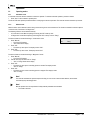
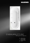
7.2
Determining the P0 minimum operating pressure for the controller
The "P0“ minimum working pressure for the device is used in facility systems with a diaphragm expansion tank.
Calculate the "P0“ minimum working pressure for the device:
•
•
The device is installed at the same level (hst = 0) as the
diaphragm expansion tank:
P0 = p0
The device is installed at a lower level than the diaphragm
expansion tank:
P0 = p0 + hst / 10
The device is installed at a higher level than the diaphragm
expansion tank:
P0 = p0 - hst / 10
p0
PIS
P0
hst
•
P0 Minimum working pressure in bar
p0 Initial pressure, diaphragm expansion tank, in bar
hst Static elevation in m
p
000198_001_R001
Note!
Calculate the filling pressure for the make-up with fresh water into the system as follows:
Filling pressure ≥ P0 + 0.3 bar
Note!
During planning, take into account that the working range of the device must be between the "PA" initial pressure and the
"PE" final pressure in the working range of the pressure maintenance.
Fillcontrol Plus — 2014-10-15
English — 25
Commissioning
7.3
Filling the device with water
1
Proceed as follows:
1. Connect the "BV" shut-off device (1) to the facility system.
2. Carefully open the shut-off device in the "WC" fresh water
line.
ST
WC
BP
DC
000199_001_R001
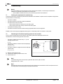
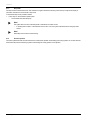
7.4
Operator panel
1
2
3
Error
Auto
4
11
10
Quit
Menu
Ok
Auto
9 8
1
2
3
4
5
6
Stop
Manual
7 6 5
Error LED
• The Error LED illuminates in the event of a fault
Display
7
"Back" to the previous menu
8
Auto LED
• The Auto LED illuminates green in Automatic mode
• The Auto LED flashes green in Manual mode
• The Auto LED is not illuminated when the system is
stopped
Stop
• For commissioning and entry of new values in the
controller
OK
• Confirm actions
Manual
• For tests and maintenance tasks
9
Auto
• For continuous operation
"Forward" to the next menu
10
Menu
• Call up the Customer menu
11
Quit
• Acknowledge messages
Selecting and changing parameters
1. Use "OK" (5) to select the parameter.
2. Use the arrow buttons (7) or (9) to change the parameter value.
3. Use "OK" (5) to confirm the parameter.
4. Use the arrow buttons (7) or (9) to change the menu option.
5. Use "Quit" (11) to switch to a different menu level.
26 — English
Fillcontrol Plus — 2014-10-15
000088_001_R001
Commissioning
7.5
Parametrising the controller in the Customer menu
Use the Customer menu to display or correct system-specific values. In the course of commissioning, the factory settings must be
adjusted for the system-specific conditions.
– For adjusting the default settings, see chapter 9.1 "Configuring settings in the controller" on page 31 .
– For information about controller operation, see chapter 7.4 "Operator panel" on page 26 .
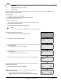
7.6
Function test
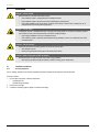
Perform a function test for the "WV" make-up valve.
• Set the device controller to manual mode, see chapter 8.1.2 "Manual mode" on page 29 . In manual mode, you can manually open
and close the "WV" make-up valve.
Proceed as follows:
1. Press "Manual".
– "Levelcontrol" mode: "WV" flashes at the display.
– "Magcontrol" mode: Use the arrow keys to select "WV". "WV" flashes at the
display.
2. Press "OK".
– The make-up valve opens. The displays shows "WV!".
– The water pressure displayed rises to the water pressure in the fresh water line.
– The make-up is completed when the value at the display no longer increases. The
make-up valve automatically closes after 10 s.
3. Press "OK".
– The make-up valve closes. The displays shows "WV".
2.0 bar
WV!
Filling
The function test of the "WV" make-up valve is completed.
Fillcontrol Plus — 2014-10-15
English — 27
Commissioning
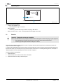
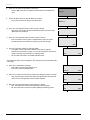
7.7
Filling system with device
In a pressure-dependent make-up, you have the option to use the device to fill the facility system with water. The following prerequisites
must be met:
• The facility system is not yet filled with water.
• The facility system has a maximum water volume of 30000 litres.
•
The shut-off valve to the facility system is open.
– Carefully open the "BV“ (1) shut-off valve.
1
WC
ST
BP
DC
000200_001_R001
Set the controller as follows:
• Select "Magcontrol" make-up, see chapter 9.1.1 "Customer menu" on page 31 .
• Select Manual mode, see chapter 8.1.2 "Manual mode" on page 29 .
Proceed as follows:
1. Press "Manual".
2. Use the arrow keys to select "Filling".
– "Filling" flashes at the display.
3. Press "OK".
– The system starts the filling process. The displays shows "Filling".
– The controller calculates the required filling pressure. As soon as the filling
pressure has been attained, the controller automatically stops the filling process.
2.0 bar
WV
Filling!
The facility system is filled with water.
Note!
Monitor the system for the entire automatic filling process.
Note!
If the maximum filling time (10 hours by default) is exceeded, the system aborts the make-up process with an error
message, see chapter 9.2 "Messages" on page 36 .
• Press "Quit" at the operator panel to acknowledge the fault message when the fault has been eliminated. The system
continues the filling process.
7.8
Starting Automatic mode
Automatic operation can be started after initial commissioning. The following prerequisites must be met for automatic operation:
• "P0" minimum working pressure is entered in the controller.
• The device is filled with water.
• All required parameters are defined in the controller.
• The function test has been concluded.
Start the automatic mode at the operator panel of the controller:
• Press "Auto" for automatic operation.
• The "Auto" LED at the operator panel illuminates to visually signal automatic operation.
Notice!
The commissioning process is now concluded.
28 — English
Fillcontrol Plus — 2014-10-15
Operation
8
Operation
8.1
Operating modes
8.1.1
Automatic mode
In automatic mode, the device is switched in continuous operation. To start the automatic operation, proceed as follows:
1. Press "Auto" on the controller's operator panel.
The "Auto" LED at the operator panel illuminates to visually signal continuous operation. The controller monitors the make-up functions.
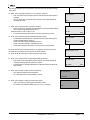
8.1.2
Manual mode
Manual mode is used to test the functions during commissioning and to service the device. The functions available for selection depend
on the set mode, "Levelcontrol" or "Magcontrol".
The following functions can be selected manually:
• In "Levelcontrol" mode: Manual opening and closing the "WV" make-up valve.
• In "Magcontrol" mode: Manual opening and closing the "WV" make-up valve or "Filling".
Proceed as follows to test the functioning in "Levelcontrol" mode:
1. Press "Manual".
– The "Auto" LED flashes.
– "WV" flashes at the display.
2. Press "OK".
– The make-up valve opens. The displays shows "WV!".
3. Press "OK".
– The make-up valve closes. The displays shows "WV".
2.0 bar
WV!
Filling
Proceed as follows to test the functioning in "Magcontrol" mode:
1. Press "Manual".
– The "Auto" LED flashes.
2. Use the arrow keys to select "WV" or "Filling".
– "WV" or "Filling" flashes at the display.
3. Press "OK".
– The make-up valve opens or the filling process is started. The displays shows
"WV!" or "Filling".
4. Press "OK".
– The make-up valve closes or the filling process is stopped. The displays shows
"WV" or "Filling".
Note!
The controller calculates the pressure required for filling. As soon as this value has been attained, the controller
automatically stops the filling process.
Note!
Manual operation can not be performed if safety-relevant parameters are exceeded.
• The switch is blocked.
Fillcontrol Plus — 2014-10-15
English — 29
Operation
8.1.3
Stop mode
Use Stop mode to shut the device down. The controller no longer monitors the functioning of the make-up. Except for the display of
information, the device is non-functional in Stop mode.
To execute the Stop mode, proceed as follows:
1. Press "Stop" on the controller's operator panel.
– The controller shuts down the pump.
Note!
The system returns an alarm if the Stop mode is activated for more than 4 hours.
– If "Floating alarm contact?" in the Customer menu is set to "Yes", the system outputs the alarm to the group alarm
contact.
Note!
Select Stop mode for device commissioning.
8.1.4
Summer operation
The make-up with fresh water must be ensured even outside of the operation of the heating and cooling systems. Do not shut down the
device when the pressure maintaining systems of the heating and cooling systems are in operation.
30 — English
Fillcontrol Plus — 2014-10-15
Controller
9
Controller
9.1
Configuring settings in the controller
9.1.1
Customer menu
Use the Customer menu to display or correct system-specific values. In the course of commissioning, the factory settings must be
adjusted for the system-specific conditions.
Proceed as follows:
1. Press "Manual" to switch to manual operation.
2. Press "Menu" to display the first main menu option "Customer menu".
You are in the "Customer menu" main menu.
To navigate and set the values:
– Use the "▼▲" arrow keys to navigate and set the values in the selected main menu.
–
–
Press "OK" to open the next sub-menu.
Press "OK" to confirm the changed setting in the sub-menu.
Note!
For a description of the operation, see chapter 7.4 "Operator panel" on page 26 .
You are in the "Customer menu" main menu.
1. Use the "▼▲" arrow keys to open the "Language" sub-menu.
2.
▼Customer menu
Press "OK" and change the desired language.
Language
3.
4.
5.
Press "OK" and change the displayed "Hour", "Minute" and "Second". The active value
to be changed flashes.
– This time is used for entries in the fault memory.
Time:
Press "OK" and change the displayed "Day", "Month" and "Year". The active value to
be changed flashes.
– This date is used for entries in the fault memory.
Date:
Press "OK" and select the required make-up variant, "Levelcontrol" or "Magcontrol".
Fillcontrol +
Magcontrol
The system displays the "Minimum working pressure" message when you have set the
"Magcontrol" make-up variant.
Min. op. pressure
6.
01.8 bar
Press "OK" and enter the minimum working pressure.
The system displays the "Safety valve pressure" message when you have set the
"Magcontrol" make-up variant.
7. Press "OK" and enter the actuating pressure for the safety valve.
– Refer to the facility system for specifying the actuating pressure of the safety
valve.
Fillcontrol Plus — 2014-10-15
(005)
Safety valve pressure
03.0 bar
(006)
English — 31
Controller
8.
9.
Press "OK" and switch into the "Make-up" main menu.
– Use the "▼▲" arrow keys to navigate and set the values in the selected main
menu.
Use the "▼▲" arrow keys to open the "Make-up" sub-menu.
– Press "Quit" to return to the previous main menu option.
10. Press "OK" and change the time for a make-up cycle, if required.
– Upon expiry of the set time, the system interrupts the make-up and returns the
"Make-up time" fault message.
Make-up >
▼Make-up
Max. make-up time
020 min.
11. Press "OK" and change the number of make-up cycles, if required.
– If the set number of make-up cycles is exceeded within 2 hours, the system
interrupts the make-up and returns the "Make-up cycles" fault message.
(023)
Max. make-up cycl.
003 / 2 h
12. Press "OK" and select a setting for "With water meter":
– Yes: FQIRA+ contact water meter is installed, see chapter 4.6 "Optional
equipment and accessories" on page 12 . This is the prerequisite for the make-up
quantity monitoring and the operation of a softening system.
– NO: A contact water meter is not installed (standard model).
(024)
With water meter
YES
(027)
The following sub-menus are only displayed if "YES" has been set in the "With water meter"
menu option.
13. Press "OK" to select "Make-up quantity".
– Press "YES" to reset the value displayed to "0".
– Press "No" to retain the displayed value.
Make-up quantity
14. Press "OK" to select "maximum make-up quantity" and change the quantity, if required.
– When the set quantity is reached, the system interrupts the make-up process and
returns the error message "Max. make-up quantity exceeded".
Max. make-up qty.
000020 l
100 l
15. Press "OK" and change the setting for "With softening", if required.
– YES: The system offers more queries regarding the softening process.
– NO: The system does not offer more queries regarding the softening process.
32 — English
Fillcontrol Plus — 2014-10-15
(028)
(029)
With softening
YES
(030)
Controller
The following sub-menus are only displayed if "YES" has been set in the "With softening"
menu option.
16. Press "OK" and change the setting for "Lock make-up", if required.
– YES: The system stops the make-up process when the set soft water capacity is
exceeded.
– NO: The system does not stop the make-up process. The system displays the
"Softening" message.
Lock make-up?
17. Press "OK" and enter the value for hardness reduction.
• Hardness reduction is calculated from the difference of the overall water hardness
GHactual and the target water hardness GHtarget.
Hardness reduction = GHactual-GHtargetl °dH.
– Consult the manufacturer information for the values of third-party products.
Hardness reduction
18. Press "OK" and enter the value for attainable soft water capacity.
– The attainable soft water capacity is calculated from the type of softening used
and the specified hardness reduction.
– Fillsoft I, soft water capacity ≤ 6000/hardness red. l
– Fillsoft II, soft water capacity ≤ 12000/hardness red. l
– Consult the manufacturer information for the values of third-party products.
Cap. soft water
The value of the remaining soft water capacity is only displayed. It cannot be set and is
calculated from the hardness reduction and the soft water capacity.
Remaining cap. soft w.
YES
10 °dH
(033)
00600 l
19. Press the "▼▲" arrow keys to switch into the next menu option.
000020 l
20. Press "OK" and enter the time for replacing the softening cartridge.
– Enter the time interval specified by the manufacturer. The system displays the
"Softening" message when this interval has expired.
– The time interval for cartridge replacement is independent od the calculated soft
water capacity.
21. Press "OK" and select a setting for "Next maintenance":
– OFF: Without maintenance recommendation.
– 001 – 060: Maintenance recommendation in months.
(031)
(032)
(035)
Replacement in
18 months
(034)
Next maintenance
012 months
22. Press "OK" and select a setting for "Floating fault contact":
– YES: For the output of all messages to the floating contact.
– NO: Output of all messages identified with "xxx" ("01", for example).
Fillcontrol Plus — 2014-10-15
Floating fault contact
YES
English — 33
Controller
23. Press "OK" and switch into the "Fault memory" main menu.
– Use the "▼▲" arrow keys to navigate and set the values in the selected main
menu.
Fault memory˃
24. Use the "▼▲" arrow keys to call the last 20 messages.
– The system stores the fault type, date, time and fault code.
– For a list of the ER fault codes and their meaning, see chapter 9.2 "Messages" on
page 36 .
25. Press "OK" and switch into the "Parameter memory" main menu.
– Use the "▼▲" arrow keys to navigate and set the values in the selected main
menu.
ER 01…xx
Parameter memory˃
26. Use the "▼▲" arrow keys to call the last 10 entries for the "P0" minimum working
pressure.
– The last 10 entries of the minimum working pressure are stored with date and
time.
P0 = xx.x bar
Date | Time
Information about the software version
Fillcontrol +
V1.00
34 — English
Fillcontrol Plus — 2014-10-15
05
11
Controller
9.1.2
Service menu
This menu is protected with a password. It can be accessed only by the Reflex Customer Service. A partial summary of the settings
stored in the Service menu is proved in the Chapter Default settings, see chapter 9.1.3 "Default settings" on page 35 .
9.1.3
Default settings
The device controller is shipped with the following default settings. Use the Customer menu to adjust these values to local conditions. In
special cases, it is possible to further adjust the values in the Service menu.
Customer menu
Parameter
Setting
Remarks
Language
EN
Display language
Fillcontrol Plus
Magcontrol
For systems with diaphragm-type pressure expansion
tank
Minimum operating pressure p0
1.5 bar
Only Magcontrol
see chapter 7.2 "Determining the P0 minimum operating
pressure for the controller" on page 25 .
Safety valve, pressure
3.0 bar
Pressure value for the safety valve of the heat generator
in the system to trip
Next maintenance
12 months
Time left to the next due maintenance
Floating alarm contact
NO
Only the messages marked in the "Messages" list
Make-up
Maximum make-up quantity
1000 Litres
Only if controller with "With water meter yes"
Maximum make-up time
20 minutes
Magcontrol
Maximum make-up cycles
3 cycles within 2 hours
Magcontrol
Softening (Only if "With softening yes")
Lock make-up
No
In the case of soft water residual capacity = 0
Hardness reduction
8°dH
= Target – Actual
Maximum make-up quantity
0 Litres
Attainable make-up quantity
Soft water capacity
0 Litres
Attainable water capacity
Cartridge replacement
18 months
Replace cartridge
Service menu
Parameter
Make-up
Pressure differential, "NSP" make-up
Pressure differential, filling pressure PF –
P0
Water quantity for each contact
Maximum filling contacts
Setting
Remarks
0.2 bar
0.3 bar
Only Magcontrol
Only Magcontrol
10 l / K
Only if a water meter is installed. (Fillset Impulse, for
example)
Limits the filling volume.
Only if a water meter is installed. (Fillset Impulse, for
example)
OFF
Fillcontrol Plus — 2014-10-15
English — 35
Controller
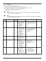
9.2
Messages
Messages with ER codes are displayed at the controller.
• Use the arrow keys at the controller operating panel to select the messages.
• By selecting the "Fault memory" main menu in the Customer menu, you display the last 20 alarms.
• Alarm causes can be eliminated by the operator or a specialist workshop.
• If required, please contact the Reflex Customer Service.
Note!
Confirm the elimination of the fault by pressing "Quit" at the controller operator panel. All other alarms are automatically
reset as soon as the cause has been eliminated.
Note!
Group messages are issued via a floating contact which is set in the Customer menu, see chapter 7.5 "Parametrising the
controller in the Customer menu" on page 27 .
ER
Code
01
Alarm
Min. pressure
06
Make-up time
07
Make-up cycles
08
Pressure measurement
10
Maximum pressure
36 — English
Group
message
YES
YES
Causes
The set value for the "P0“
minimum working pressure
has been exceeded.
• Water loss in the
system.
• Expansion tank
defective.
Set time for the make-up
time has been exceeded.
• Severe water loss in
the system.
• Make-up line not
connected.
• Make-up rate
insufficient.
• Make-up hysteresis
too high.
Set value for the make-up
cycles has been exceeded.
• Leakage in the
system.
Controller receives
incorrect signal.
• Pressure transducer
plug not plugged in.
• Broken wire from
"PIS“ pressure
transducer.
• "PIS" pressure
transducer defective.
Set value for the maximum
pressure has been
exceeded.
• Safety valve defective.
• Insufficient
dimensioning of the
pipeline to the system.
Remedy
Alarm reset
•
•
•
Check the system for leaks.
Replace the expansion tank.
Check the function in manual
mode.
"Quit"
•
•
•
•
Check the system for leaks.
Connect the make-up system.
Check the make-up rate.
Check the make-up
hysteresis.
"Quit"
•
Check the system for leaks.
"Quit"
•
•
•
Plug in the plug.
Replace the wire.
Replace the "PIS“ pressure
transducer.
"Quit"
•
Check the actuating pressure
of the safety valve.
Replace the safety valve.
Increase the diameter of the
pipeline to the system.
"Quit"
•
•
Fillcontrol Plus — 2014-10-15
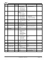
Controller
ER
Code
11
Alarm
Make-up quantity
12
Filling time
13
Filling volume
Group
message
Set value of the water meter
has been exceeded.
• Leakage in the system.
• Water quantity per
contact incorrectly set
in the Service menu.
Set value for the maximum
filling time has been
exceeded.
• System volume too
large (≤ 3000Liter).
• System volume too
large (≤ 3000Liter).
• Water quantity per
contact incorrectly set
in the Service menu.
Make-up without demand
• "WV" make-up valve
leaking
No power.
The device is in Stop mode
for more than 4 hours.
Set value for the make-up
quantity has been
exceeded.
Set value exceeded.
15
Make-up valve
16
19
Power failure
Stop > 4 h
20
Max. Make-up volume
21
24
Maintenance
recommended
Softening
30
I/O module fault
31
EEPROM defective
YES
32
33
Undervoltage
Adjustment parameter
faulty
Main board
communication faulty
YES
34
35
36
Digital input voltage
faulty
Analogue input voltage
faulty
Causes
•
Set value for the water
capacity has been
reached.
• Time interval for
replacement of the
softening cartridge has
been reached.
• I/O module defective.
• Connection between
option card and
controller faulty.
• Option card defective.
• EEPROM defective.
• Internal calculation
error.
Supply voltage too low.
EPROM parameter memory
defective.
• Connecting cable
defective.
• Main board defective.
Short-circuit of input
voltage.
Short-circuit of input
voltage.
Remedy
Alarm reset
•
•
Check the system for leaks.
Check the set value.
"Quit"
•
Restart the filling process
"Quit"
•
If necessary, restart the
filling process
Set the water quantity per
contact in the Service menu.
"Quit"
•
•
Replace the "WV" make-up
valve
Check power supply.
Select Automatic mode.
–
–
Reset the "Make-up quantity"
meter in the Customer menu.
"Quit"
Carry out maintenance.
"Quit"
Replace the softening cartridge.
"Quit"
Contact the Reflex Customer
Service.
Contact the Reflex Customer
Service.
"Quit"
Check power supply.
Contact the Reflex Customer
Service.
Contact the Reflex Customer
Service.
Check the wiring at the digital
inputs (water meter, for example).
Check the wiring at the analogue
inputs (pressure/level).
Fillcontrol Plus — 2014-10-15
English — 37
Maintenance
10
Maintenance
Danger – electric shock!
•
Risk of serious injury or death due to electric shock.
– Ensure that the system is voltage-free before installing the device.
– Ensure that the system is secured and cannot be reactivated by other persons.
– Ensure that installation work for the electric connection of the device is carried out by an electrician, and in
compliance with electrical engineering regulations.
Caution – risk of burning!
•
Risk of burning due to escaping medium.
– Maintain a sufficient distance from the escaping medium.
– Wear suitable personal protective equipment (safety gloves and goggles).
Caution – risk of injury!
•
Incorrect installation or service work may cause burns and other injuries at the connections when hot water or steam
suddenly escape at pressure.
– Ensure proper disassembly.
– Ensure that the system is de-pressurised before performing the disassembly.
Note!
Ensure that maintenance is carried out annually.
• In specific cases, the maintenance intervals depend on the operational conditions.
Note!
The annual maintenance is displayed upon expiry of the set operating time.
• Use the "Quit" button to confirm the "Maintenance received" message.
• Reset the maintenance counter in the Customer menu.
Note!
Maintenance tasks must be carried out only by specialist personnel or the Reflex Customer Service.
•
Confirm the maintenance tasks, see chapter 10.3 "Maintenance certificate " on page 40 .
38 — English
Fillcontrol Plus — 2014-10-15
Maintenance
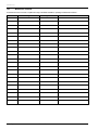
10.1
Maintenance schedule
The maintenance schedule is a summary of maintenance tasks to be carried out regularly.
Maintenance task
▲ = Check, ■ = Service, ● = Clean
Check for leaks, see chapter 10.2 "Exterior leak test" on page 39 .
• Screw connections.
Check the make-up function, see chapter 7.6 "Function test" on page 27
.
Check the system-specific setting values in the controller, see chapter
9.1.1 "Customer menu" on page 31 .
• Mindestbetriebsdruck „P0“.
• "PSV“ safety valve pressure.
▲
Conditions
Interval
■
Annually
▲
Annually
▲
Annually
Note!
Compare the minimum working pressure with the initial pressure in the diaphragm expansion tank.
– If necessary, adjust the initial pressure in the diaphragm expansion tank.
10.2
Exterior leak test
Check the following device components for leaks:
– "PU“ pumps and screw fittings.
• Seal any leaks at the connections or replace the connections, if required.
• Seal leaking screw connections or replace, if required.
Fillcontrol Plus — 2014-10-15
English — 39
Maintenance
10.3
Maintenance certificate
All maintenance tasks have been completed according to the Reflex Installation, Operating and Maintenance Manual.
Date
40 — English
Service organisation
Signature
Fillcontrol Plus — 2014-10-15
Remarks
Disassembly
11
Disassembly
Danger – electric shock!
•
Risk of serious injury or death due to electric shock.
– Ensure that the system is voltage-free before installing the device.
– Ensure that the system is secured and cannot be reactivated by other persons.
– Ensure that installation work for the electric connection of the device is carried out by an electrician, and in
compliance with electrical engineering regulations.
Danger – electric shock!
•
Risk of serious injury or death due to electric shock. Some parts of the main board may still carry 230V voltage even
with the device physically isolated from the 230 V power supply.
– Before you remove the covers, completely isolate the device controller from the power supply.
Caution – risk of burning!
•
Risk of burning due to escaping medium.
– Maintain a sufficient distance from the escaping medium.
– Wear suitable personal protective equipment (safety gloves and goggles).
Caution – risk of injury!
•
Incorrect installation or service work may cause burns and other injuries at the connections when hot water or steam
suddenly escape at pressure.
– Ensure proper disassembly.
– Ensure that the system is de-pressurised before performing the disassembly.
Proceed as follows:
1. Prior to dismantling, block off all "water"-side connections to the device.
2. Disconnect the system from the power supply and secure it against unintended reactivation.
3. Disconnect the power cable of the device from the power supply.
4. Disconnect and remove all cables from the terminals of the device controller.
5. Undo all hose and pipe connections between the device and the system and remove them completely.
6. Drain all water from the device.
7. If necessary, physically remove the device from the system.
The device is removed.
Fillcontrol Plus — 2014-10-15
English — 41
Annex
12
Annex
12.1
Reflex Customer Service
Central customer service
Switchboard: Telephone number: +49 (0)2382 7069 - 0
Customer Service extension: +49 (0)2382 7069 - 9505
Fax: +49 (0)2382 7069 - 523
E-mail: [email protected]
42 — English
Fillcontrol Plus — 2014-10-15
Annex
12.2
Conformity and standards
Declaration of conformity for electrical installations in the pressure maintaining, make-up or degassing systems
1.
We hereby confirm that the products meets the essential protection requirements
as established in the Council Directive to approximate the laws of the Member
States relating to electromagnetic compatibility (2004/108/EC).
The following Standards have been applied to assess the products:
Deutsches Institut für Normung, European
Standard 61326 – 1:2006-10
2.
We hereby confirm that the control cabinets meet the essential requirements of
the Low-voltage Directive (2006/95/EC).
The following Standards have been applied to assess the products:
Deutsches Institut für Normung, European
Standard 61010 – 1:2002-08, Occupational
Health and Safety Regulations of the trade
associations Para 2
The manufacturer declares that the pressure equipment (the assembly)
Manufacturer
complies with the requirements of Directive 97/23/EC.
Reflex Winkelmann GmbH
Gersteinstraße 19
D - 59227 Ahlen - Germany
Telephone: +49 (0)2382 7069-0
Fax: +49 (0)2382 7069-588
Norbert Hülsmann
Volker Mauel
E-mail: [email protected]
Members of the Board of Directors
Fillcontrol Plus — 2014-10-15
English — 43
Annex
12.3
Guarantee
The respective statutory guarantee regulations apply.
12.4
System
Hysteresis
Cavitation
Cumulated
Klixon
Permeation
44 — English
Glossary
Heating, climate control or other building services system to which the device is connected.
Delayed behaviour of an output variable relative to the input variable.
(The input signal influences the output signal)
Formation and dissolution of vapour-filled cavities (vapour bubbles) in fluids.
Cumulation of values.
Pressure safety cut-out for the protection of the pump motor.
Process in which a substance (permeate) penetrates or migrates through a solid body.
Fillcontrol Plus — 2014-10-15
SI1417en / 9125047 / 04-14
Reflex Winkelmann GmbH
Gersteinstraße 19
59227 Ahlen, Germany
Telephone: +49 (0)2382 7069-0
Fax: +49 (0)2382 7069-588
www.reflex.de