1
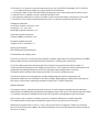
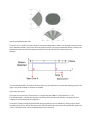
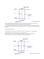
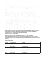
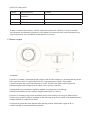
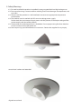
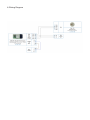
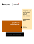
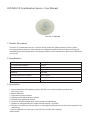
LED DALI CS Combination Sensor - User Manual
Item No.: LC-004-600
1. Product Description
The DALI CS Combination Sensor is a Sensor unit for automatic lighting control in DALI systems
wit integrated Licht intensiry measurement and additional temperature sensor for measuring and
monitioring the room temperature. The compact module can be mounted in a flush box or directly on
cavity walls.
2. Specifications
power supply
typ. current consumption
Input/Output
function
shellcolor
via DALI- Bus
3.5 mA
DALI
adjustable
RAL9010
connecting wire cross section
Dimensions (L x W x H) in mm
0,5-1,5 mm2
98 x 9 x 30 mm
weight
48g
3. Description
1. Sensor Module for DALI lighting systems with focus on automatic lighting control and
low energy costs
2. Motion detection
3. Light intensity measurement
4. Lighting control dependent on motion
5. Ambient light dependent control
6. Sensor for ambient temperature measurement and monitoring
7. Optional an integrated IR or RF remote control receiver is available.
8. The DALI CS module can be used either as active lighting control unit or just for measurements and
monitoring.
9. Sensor properties are set easily via the DALI-line and the “DALI-Cockpit”
software tool.
10. The DALI CS is able to transmit DALIcommands (e.g. ON, OFF, RECALL MIN/MAX, GO TO SCENE X, …) to single destination addresses, group addresses or broadcast.
11. The rotary switch on the back of the housing helps to assign a destination group address easily.
12. Several DALI CS modules can be used within one DALI-line.
13. The compact module can easily be installed in recessed conduit boxes or directly on cavity walls.
14. The DALI CS must not be connected to the mains. It is directly supplied by the DALI-line.
PIR Motion Detection:
sensibility: 92 zones, distance: <12m
range: hor.: ±51°, vert. ±46°
temp.diff. target to ambience: >4°C
Light Intensity Measurement:
range: 0-2500lux, resolution: 1lux
Temperature Measurement:
range: 0°C-70°C, resolution: 1°C
optional (on request):
IR or RF Remote Control Receiver
Functionality and Configuration
The DALI CS measures various physical properties (motion, light intensity and temperature) and offers
the possibility to react according to the measurements by sending DALI commands.
Via a DALI-USB interface the software tool “DALI-Cockpit” can communicate with the DALI CS.
So the desired functionality can be configured easily on PC. DALI-Cockpit and DALI-USB interface are
required for the configuration only and can be removed when configuration is finished.
For further details check the DALI tutorial and DALI CS and DALI Cockpit manuals.
The settings of the sensor components and the configuration of the DALI commands and
destination addresses can be defined in the DALI Cockpit. Before going in detail the functionality of
the sensors and the basic operating conditions of the DALI CS will be explained.
Motion Detection
The motion sensor is spatially divided into 92 zones. In each zone the received thermal radiation is
determined and differentially compared to the adjacent zones (PIR sensor). For motion detection there
is a need for a temperature difference of at least 4°C between moving object and environment.
Heat sources such as copiers or heaters may have a negative influence on motion detection.
This method allows observation of relatively large areas by using only one sensor head.
With opening angles of 46.3° and 51.3° and a sensor mounted at a height of 5 meters the 92 zones
cover an area of more than 100m2. The distance between sensor and the object of interest should be
less than 12 meters.
opening angel/detection area
The DALI CS can send DALI commands on movement detection as well as on disappearance of a previously detected motion. In the case of the disappearance of a previously detected motion a delay time
between the occurrence of the event and the transmission of the DALI command can be
defined.
This functionality offers a simple and convenient way to implement an automatic lighting control. The
light is turned on and off as reaction on motion.
Light Intensity Sensor
The light sensor measures illuminance in a range from 0 to 2500 lux. The resolution is 1 lux.
The incident light is rated by the spectral sensitivity of the human eye and thus a property for the
subjective visual perception of brightness.
In the DALI-Cockpit switching threshholds for light intensity can be defined by setting values for threshold and hysteresis. When the measured value falls below the lower limit or exceeds the upper one
various DALIcommands can be selected to be sent as response.
hysteresis light sensor
Besides direct lighting control the light sensor can be used for measurement and monitoring
as well. The measured value can be transmitted to a superimposed control.
A combined functionality of light intensity sensor and motion detector can be selected optionally.
With this option the motion sensor can be forced to work only at night while it is deactivated during
daytime.
Temperature Measurement
The temperature sensor covers a range from 0°C to 70°C. The resolution is 1°C. The setting of
switching thresholds is implemented similar to the light sensor.
The temperature sensor can be used for measurement and monitoring purposes only.
The measured value can then be transmitted to a higher level controller.
hysteresis temperature sensor
Optional Sensors
On request the DALI CS is available with infrared (IR) or radio frequency (RF) remote control receiver.
The transmission of DALI commands can then be manually triggered by a remote control.
Configuration
For applications requiring a motion sensor only the default configuration may be sufficient.
The destination address can be set by the rotary switch on the rear side of the sensor
(0…Broadcast, 1…15 -> group addresses G0…G14). In the default configuration light- and
temperature-sensor are deactivated. The motion sensor sends the DALI-command
RECALL MAX in case of a detected motion and the DALI-command OFF (without delay) if
movement isn’t detected any longer. The destination address is G0...G14 or broadcast as selected by
the rotary switch.
For any other configuration the free DALICockpit software tool can be used to adjust
the sensor individually. In the DALI-Cockpit the DALI addressing procedure can easily be initiated.
After addressing has finished the spatial localization of any DALI CS can be done by forcing the
desired sensor to turn on a red LED. Therefore select the check box to switch on the LED in
the DALI Cockpit. The relationship between spatial arrangement and assigned number in
the software is simply established that way.
The parameters like threshold and hysteresis of light intensity measurement and temperature sensor
can be configured in the DALI Cockpit as well as the delay time of the PIR sensor.
Moreover each sensor can be separately enabled or disabled.
When a defined event (such as crossing temperature thresholds or detected motion) occurs, each
sensor module can send freely configurable DALI-commands (Send Cmd X/Y) to up to four
destination addresses. In contrast to the default setting multiple
destination addresses can be selected.
These can be either individual addresses or group addresses as well as broadcast.
Besides the destination addresses the DALIcommand to be transmitted must also be selected.
Available DALI-commands can be separated into commands for Switching On (CmdX) and Switching
Off (CmdY).
CmdX (ON-commands):
CmDNr.
Command Name
Funtction
-
DIRECT ARC
POWER>0
direct arc power in %
5
RECALL MAX
recalls MAX value
6
RECALL MIN
recalls MIN value
8
ON AND STEP
UP
Increases light level by one
increment, if OFF switch
ON (MIN value)
16-31
GO TO SCENE
go to scene 0-15
CmdY (OFF-commands):
CmDNr.
Command Name
Function
-
DIRECT ARC
POWER>0
direct arc power in %
0
OFF
light off
16-31
GO TO SCENE
go to scene 0-15
If there is no destination address, no DALI commands will be sent. The DALI CS may be used for
measurement and monitoring purposes in this mode. The measured values can be retrieved using
special commands. For more details check the DALI CS manual.
4. Abmessungen
Installation
The DALI CS module is connected to the DALIline. Like all DALI modules it is powered directly via the
DALI signal line, which is supplied by a DALI PS. A separate power supply is not needed.
A typical value for the current consumption is 3.5mA. The DALI-line input is polarity free and
protected against overvoltage of up to 270Vac. DALI signals are not SELV.
Therefore the same procedures should be applied as working with main voltage.
Allowed connection wire cross sections range from 0.5mm2 to 1.5mm2.
The DALI CS mounting ring can be attached to cavity walls directly or by using an electrical box.
The housing can then simply be attached on the mounting ring. Even in a flush-mounted box there is
enough room for a sunken sensor head.
Finally the sensor head can be aligned to the desired position. Declination angles of 40° in
vertical and 360° in axial direction are provided.
5. Safety Warnings
6.1. To avoid installed the product in minefield, strong magnetic field and high voltage area.
6.2. To ensure the wiring is correct and firm avoiding short circuit damages to components and
cause fire.
6.3. Please install the product in a well ventilated area to ensure appropriate temperature
environment.
6.4. The product must be worked with DC constant voltage power supply.
Please check the consistence of input power with the product, if the output voltage of the
power comply with that of the product.
6.5. Connect the wire with the power on is forbidden. Ensure proper wiring first then check to
ensure no short-circuit, then power on.
6.6. Don‘t repair it by yourself whenever an error occur. Contact the supplier for any inquiry.
sensor head: sunken and extended
aligned sensor head
6. Wiring Diagram