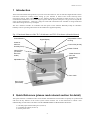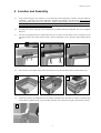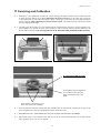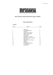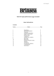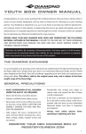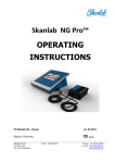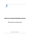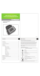
1
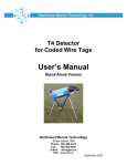
HD401 US Issue 01
®
TLC-40 Advance / TLC-50 Advance
Thermal
Life-support
Cabinet
User instructions
Contents
Section
Subject
Page
1
2
3
4
5
6
7
8
9
11
12
13
Introduction
QUICK REFERENCE
Unpacking
Location and Assembly
Digital Control System
Temperature
Humidity and Ventilation
Introducing Young Birds
Internal Lighting
Cleaning up
Servicing and Calibration
Specification
2
2
4
5
6
8
9
9
10
10
11
12
IMPORTANT NOTICE
Brinsea® Products Ltd and its agents or distributors will not be responsible for loss of
animals in the event of failure however caused and the user is advised to arrange his
own insurance cover where loss of power or mechanical or electrical failure might
result in unacceptable losses.
1
HD401 US Issue 01
1 Introduction
These instructions detail the operation of your new TLC-40 Advance or TLC-50 Advance digital brooder. Please
read these instructions carefully before setting up your machine to achieve best results and keep these
instructions safe for future reference. Your TLC Advance brooder is designed to allow the user to vary the
environmental conditions to suit a wide range of species and the specific set-up for every species is beyond the
scope of these instructions. There are a range of books and veterinarian texts available covering animal and
avian hand rearing and recovery techniques
The TLC Advance brooders are available with the option of the Advance Humidity Pump for automatic
humidity control. Operating instructions for this module are supplied separately.
Fig. 1 Functional features of the TLC-40 Advance and TLC-50 Advance (40 model shown)
Control Buttons
Digital Display
Outlet for
Advance
Humidity Pump
Temperature Control
Housing
Power Inlet (at rear)
Water Fill Hole
Inlet Air Filter
(circulation
filters are
inside)
Water Reservoir
Pan and
Evaporating
Block
Adjustable Vent
Door Latch
Door Hinges
(Reversible)
2 Quick Reference (please read relevant section for detail)
This quick reference is intended to allow users familiar with Brinsea® TLC brooders to quickly set up the brooder
and learn the key features of the control system. Please read the rest of the instructions to obtain a full
understanding of each feature. DO NOT COVER THE BROODER. FOR INDOOR USE ONLY.
1) Carefully unpack the brooder parts (section 3)
2) Assemble the cabinet (section 4)
3) Fit the power lead
2
HD401 US Issue 01
MAIN MENU – QUICK REFERENCE
PRESS BOTH BUTTONS TO UNLOCK THE MAIN MENU
SELECT THE OPTION / RETURN TO THE MENU.
GO FORWARD ONE SCREEN / INCREASE THE VALUE / DISPLAY IN CELSIUS.
GO BACK ONE SCREEN / DECREASE THE VALUE / DISPLAY IN FAHRENHEIT.
30.0C OK - + TEMPERATURE.
RANGE 20.0 – 40.0°C (68.0 – 104.0°F).
DEFAULT 30.0°C (86.0°F).
RH% OK Å Æ RH 20% EX ONLY RELATIVE HUMIDITY.
RANGE 20% – 80%.
DEFAULT 20%.
ONLY FOR EX VERSION WITH
ADVANCE HUMIDITY PUMP – SEE
SECTION 7.
ALARM HI OK Å Æ HI 2.0C OK - + HIGH TEMPERATURE ALARM.
RANGE 1.0 – 5.0°C (1.8 – 9.0°F) ABOVE
SET BROODER TEMPERATURE.
DEFAULT 2.0°C (3.6°F).
ALARM LO OK Å Æ LOW 3.0C OK - + LOW TEMPERATURE ALARM.
RANGE 1.0 – 5.0°C (1.8 – 9.0°F) BELOW
SET BROODER TEMPERATURE.
DEFAULT 3.0°C (5.4°F).
C/F OK Å Æ DISP C OK C F CELSIUS / FAHRENHEIT DISPLAY.
SWITCHES ALL TEMPERATURE
FIGURES BETWEEN °C AND °F.
DEFAULT °C.
TEMP OK Å Æ SAVE OK Å Æ SAVE.
ALL CHANGES ARE SAVED. RETURN
TO NORMAL OPERATION SCREEN.
CANCEL OK Å Æ CANCEL.
ALL CHANGES ARE IGNORED.
RETURN TO NORMAL OPERATION
SCREEN.
3
HD401 US Issue 01
3 Unpacking
Your brooder has been supplied in protective packaging. Please remove all tape, strapping and packing from the
brooder and parts. Retain the carton and packing materials to enable the unit to be repacked.
Your brooder will include as standard:
Quantity
Item
1
1
1
1
1
1
1
1
1
Brooder top assembly (with 3 air filters fitted)
Cabinet base
Door
Hinge socket
Fastener and tool kit
Mains cable
Water pan
Evaporating block
Water funnel
Fastener and Tool Kit Contents:
Quantity TLC-40
Quantity TLC-50
Item
2
2
M5 x 16mm countersunk screws
2
2
M5 flat washers
2
2
M5 domed nuts
12
16
M4 x 30mm cap-headed screws
12
16
M4 star washers
12
16
M4 domed nuts
1
1
1
1
1
1
3mm hex key
4mm hex key
7mm / 8mm wrench
3.1
Please identify each part and check that they are all present and undamaged. If there are any parts
damaged or missing please contact your retailer or Brinsea® Products (at the address at the end of the
document).
3.2
Note that if your brooder has been ordered with additional options (such as the Advance Humidity Pump)
separate instructions and component lists apply.
3.3
Check also that the electrical supply matches the machine’s requirements (marked on the technical label
next to the power inlet socket).
3.4
To register your new Brinsea® product please visit www.brinsea.com and follow the link under Customer
Service on the top navigation of the home page to qualify for your free 2 year guarantee. If you do not
have access to the internet please call 1-888-667-7009.
3.5
Go to www.Brinsea.com and register as a free member of the Brinsea® Email Group to receive the latest
news and information such as advance notice about new products, special offers, exclusive competitions
and much more.
4
HD401 US Issue 01
4 Location and Assembly
4.1
Your brooder will give best results in a room free from wide temperature variations and with generous
ventilation – particularly if several incubators / brooders are running at the same time. Ensure that the
room temperature cannot drop on a cold night. Ideally thermostatically control the room at between 68
and 77°F (20 and 25°C). Never allow the room temperature to drop below 59°F (15°C) and ensure that
the brooder cannot be exposed to direct sunlight.
4.2
Assemble the cabinet using the tools and fasteners provided. Follow the diagrams. Do not over-tighten
fasteners.
4.3
The door is hinged at the left as supplied but may be reversed to provide better access if required. Fit the
top hinge socket to the cabinet using the M5 x 16mm countersunk screws, M5 flat washers and M5 dome
nuts.
1
4.4
2
3
Place the door in the lower hinge and close the latch. Lower the top cabinet down onto the other parts.
4
4.5
5
6
Fit the M4 x 30mm cap-headed screws, star washers and dome nuts into each set of holes around the edge
of the cabinet. Tighten enough to prevent them spinning. This creates an air tight seal around the cabinet.
7
5
HD401 US Issue 01
4.6
Place the white evaporating block upright in the clear water pan. Open the door and lift the pan into
position, it pushes up and across into two slots on the heater enclosure. The pad may need to be softened
with a little water to help it flatten while the pan is fitted. The pan is located in this manner to help
prevent accidental removal by animals.
Air Filter
8
9
4.7
Your brooder is supplied with air filter media fitted at the air inlet (see fig 1) and at each end of the heater
enclosure (see picture 9 above). For details of filter replacement see the Servicing section.
4.8
Place the brooder on a scratch and moisture resistant surface. Worktop height is ideal.
4.9
Connect the mains cable to the inlet. Ensure the connector is pushed fully home in its socket.
4.10
The fan will start and the display will show the current temperature and humidity in the cabinet plus a "P"
symbol to show power was interrupted.
4.11
Allow the brooder to run for at least an hour to stabilise the temperature before making adjustments or
introducing animals.
5 Digital Control System
T*30.0C H*40% The TLC Advance control system utilises highly accurate, individually calibrated sensors for temperature and
humidity. Be cautious of low cost analogue or digital thermometers and hygrometers when comparing them with
the brooder display readings.
6
HD401 US Issue 01
5.1
NORMAL OPERATION – Temperature and relative humidity are continuously displayed.
The asterisk “*” adjacent to the temperature reading shows when the heater power is on. When warming
the asterisk will be continuously on, once warmed up the asterisk will slowly flash as the heater is pulsed
to maintain the correct temperature. When reducing the temperature setting the asterisk may go off, this is
normal.
The asterisk “*” adjacent to the relative humidity display is only on when the pump control output is on
(see section 8) and is only applicable when using the optional Brinsea Advance Humidity Management
Module.
5.2
POWER LOSS DISPLAY – If power has been interrupted due to a power cut (or when first switching
on) a “P” is shown flashing in the corner of the display. Press the - or + button for 2 or more seconds to
clear the indicator. If the reason for the power loss is not known check the power cable connections are
secure.
T*30.0C H 40% P 5.3
HIGH TEMPERATURE ALARM DISPLAY – If the measured temperature goes up by more than the
figure in the ALARM HI screen, the alarm will sound immediately and “+T” will be displayed. Press OK
to silence the alarm for 30 minutes.
If the high temperature problem rectifies itself the “+T” remains on the display to show this has
happened. Press OK to clear the indicator. Check the brooder is not (and has not been) in direct sunlight
or too near a heat source such as a room heater.
T 39.8C H 23% +T 5.4
LOW TEMPERATURE ALARM DISPLAY – If the measured temperature goes down by more than the
figure in the ALARM LO screen, after 30 minutes “-T” will be displayed and the alarm will sound. Press
OK to silence the alarm for 30 minutes.
If the low temperature problem rectifies itself the “-T” remains on the display to show this has happened.
Press OK to clear the indicator. Check the brooder is not (and has not been) in a cold draught or that the
room temperature has dropped significantly.
T*32.1C H 45% -T 5.5
CHANGING SETTINGS – The Main Menu allows the various settings to be modified and saved. All
changes are retained in the event of a power cut.
To access the Main Menu press the + and – buttons simultaneously to unlock the display. For full details
of menu settings please refer to the guide on page 3.
7
HD401 US Issue 01
6 Temperature
Stable and correct temperature is essential for good results. Adjust with care.
6.1
Note: your brooder may not be set to the correct temperature from the factory and the following
procedure must be followed before introducing animals.
6.2
As the brooder warms up and approaches its control setting the heater on asterisk “*” will change from
continuously on to flashing. Allow the brooder to stabilise for at least an hour before adjusting the
temperature.
6.3
Press the - and + buttons simultaneously to unlock the main menu. Press OK to select the temperature
screen and adjust as necessary using the + and – buttons. Press OK to return to the Main Menu and then
scroll down to Save. Press OK to save the changes. When reducing temperature the asterisk may go out
while the brooder cools – this is normal.
6.4
Refer to the digital temperature display to check temperature. The display shows the air temperature in
increments of 0.1°.
6.5
The Display can be switched to show all temperature settings in degrees Fahrenheit. Press the - and +
buttons simultaneously to unlock the main menu. Scroll to the C/F option and press OK to select the C/F
display screen. Press the + button to select °F or the – button to select °C. Press OK to return to the Main
Menu and then scroll down to Save. Press OK to save the changes.
6.6
TEMPERATURE GUIDELINES FOR BROODING HATCHLING CHICKS. As a general rule a newly
hatched chick will need a brooder temperature a little lower than incubation temperature, about 95-97°F
(35-36°C) and the temperature can be reduced progressively at about 1°F (0.5°C) per day until it is fully
feathered or no longer requires supplementary heat. In warm ambient conditions this will be sooner than
in cold climates. When brooding temperatures are just above room temperature the asterisk heater
indicator may go out (indicating that no heat is being applied). This indicates that the birds are ready to be
moved to a nursery cage. If room temperature then drops (e.g. at night) then the birds can be kept warm
by replacing them into the TLC brooder.
6.7
Where there is to be a continuous throughput of birds of differing stages of development, several TLC
brooders can be set to different temperatures and the birds moved to cooler units as they grow.
6.8
The Recommended staged temperature settings for most parrots and falcons:
Days 1 to 5
Days 6 to 10
Days 11 to 15
Days 16 to 25
97°F (36°C)
91°F (33°C)
85°F (29.5°C)
80°F (27°C)
These temperatures have been found to promote optimal health and growth from newly hatched chicks
and are a little higher than may be found in nests. Where birds are taken from a nest after more than a
few days, the temperature setting will usually need to be a few degrees lower to prevent heat stress. The
recommendations above are for guidance only, always observe the chick’s behaviour (see below) to
verify setting.
Temperatures too high can cause heat stress, dehydration, deformities or haemorrhaging under the skin.
Low temperature may reduce appetite and retard growth. Observation of the bird is the best guide to its
comfort. Chicks try to huddle together if cold and move about seeking parental warmth. Chicks too warm
separate and pant. In either case they will complain vocally. Comfortable birds will lie quietly sleeping with
wings loosely folded at the sides, usually in contact with one another.
6.9
The TLC-40 Advance and TLC-50 Advance have a built-in temperature alarm which warns of high or
low temperatures. See section 5 for details.
6.10
Developing chicks are fairly tolerant of short-term temperature drops but care should be taken about
cooling that occurs during feeding or inspection. Keep the room warm, hold the bird in a cloth to prevent
chilling from cold hands and use warmed feeding utensils.
8
HD401 US Issue 01
7 Humidity and Ventilation
Elevated air temperatures in the TLC brooder will reduce the relative humidity level(RH) and can cause
dehydration. A water reservoir is fitted to counteract this effect.
7.1
Your TLC brooder is fitted with a water reservoir (see fig.1) which humidifies air as it is drawn into the
heater enclosure. Use a solution of Brinsea® Incubation Disinfectant (1part concentrate to 100 parts water)
in the water reservoir (pan) to inhibit bacterial build-up. It is recommended that the reservoir is topped up
with solution daily to reduce dehydration. This can be a particular problem with chick(s).
Relative humidity of between 45 and 55% RH is adequate for brooding. Avoid very high levels as
condensation may form on cooler surfaces.
7.2
The brooder and its occupants need not be disturbed to fill the water pan. Use the funnel provided to pour
water through the water fill point in the top of the brooder (see fig. 1) directly onto the evaporating block
and into the water pan. Push the funnel down gently into the hole to make sure the water pours directly in.
Clean up any spilled water from the top of the brooder immediately.
7.3
To further increase humidity levels within the brooder the water reservoir is fitted with an evaporating
block of absorbent paper mesh as standard. This block may be set across the water pan (instead of
upright) or removed entirely to give lower humidity levels. The block can provide a breeding ground for
bacteria. In addition to the use of Brinsea® Incubation Disinfectant concentrate in the water, it is
recommended that the block is replaced every 2 months of use.
7.4
An adjustable vent is fitted to the door of the brooder which may be opened or closed to give greater
control of humidity (close vent to increase) and fresh air flow. The vent may be fully closed as fixed
ventilation is also provided.
7.5
The Brinsea® Advance Humidity Pump is available as an option for the TLC Advance brooder. The
brooder digital control system not only reads the humidity in the brooder but it provides a control signal
to operate the water pump and accurately maintain the humidity level at the desired level.
8 Introducing Young Birds
Once the correct temperature has been established and the air humidified the TLC brooder is ready for
use.
8.1
For newly hatched chicks use small plastic tubs such as ice-cream or butter / spread containers lined with
paper towel. Young birds of similar age and size can be placed together and benefit from the warmth and
comfort. If disparity in size is too great the smaller animal is at risk of being crushed or smothered.
8.2
For larger chicks and adult birds line the base of the TLC brooder with paper towelling and place the
bird(s) directly on this. The brooder cabinet material is smooth and designed to be easy to clean.
8.3
Change paper towel at each feed or at least four times a day.
8.4
Follow feeding regimes recommended for your species ensuring the highest standards of hygiene at all
times.
8.5
In order to maintain maximum air-flow the air-flow filters should be checked once a week for dust or
down, and cleaned if necessary.
9
HD401 US Issue 01
9 Internal Lighting
9.1
The TLC Advance brooders are equipped with gentle, internal LED lighting for night-time inspection of
animals and birds. The LED lamps are energy efficient, do not affect temperature and would not normally
require replacement. Amber colour LED's do not produce UV light often associated with "white" LED's.
9.2
The LED lights are located to the left of the fan diffuser in the TLC-40 size model and on both sides of
the fan diffuser on the larger TLC-50 model.
9.3
The lights may be switched on and off by pressing the OK button. This has a toggle action.
LED lamp
location
(TLC-50
only)
LED lamp
location
(TLC-40 and
TLC-50)
10 Cleaning Up
IMPORTANT:
DISCONNECT THE BROODER FROM THE MAINS POWER SUPPLY DURING CLEANING. RISK OF
ELECTRIC SHOCK! ENSURE THAT ALL ELECTRICAL PARTS ARE KEPT DRY.
10.1
Following each brood in your TLC brooder remove all debris from the floor. Wipe all internal surfaces
with a soft cloth soaked in 100:1 Brinsea® Incubation Disinfectant solution. Filters should be inspected on
a weekly basis and be cleaned if necessary. Remove all three filters and gently hand wash in warm water
then allow them to dry before use. Filters need replacing every six months. Immerse and soak any nest
tubs in disinfectant solution. The exterior of the TLC brooders may be cleaned with a damp cloth.
USE WATER BASED DISINFECTANTS ONLY WHEN CLEANING
10.2
Always clean the TLC brooder before storage and ensure that the unit is totally dry inside and out or
damage may occur to the components.
10.3
For deeper cleaning the base of the cabinet and the door may be removed by releasing the fasteners. See
section 4 for assembly guide. The cabinet base and the door may be wet-cleaned with mild detergent and
then disinfected with water based disinfectant solution such as Brinsea® Incubation Disinfectant.
Replacement filters, evaporating blocks and disinfectant solution are all available from Brinsea® Products at the
address at the end of this document or from your Brinsea® agent.
10
HD401 US Issue 01
11 Servicing and Calibration
11.1
Although it is not regarded as necessary for routine cleaning, the heater enclosure may be safely removed
to allow the heater and fan to be dusted. Disconnect the power lead. Remove the water pan. Loosen the
4 cap-head screws (on top of the white plastic cabinet, not the grey control box) as shown and then finally
remove each one while supporting the metal enclosure inside. The metal enclosure will fall if not held
and may damage the brooder.
11.2
Carefully place the brooder on its top and then lift out the metal heater enclosure. The fan assembly may
then be hinged over toward the front of the machine so that the heating element and fan blades may be
dusted with a soft brush. USE NO LIQUIDS. DO NOT DISTURB THE TEMPERATURE SENSOR.
DO NOT DISTURB SENSOR
Fan assembly may be hinged out
on its cables to allow fan and
heater to be dusted with a soft
brush
Fan assembly is located by 4 pegs
in the feet of the clear moulding
11.3
Once the heater area has been dusted the fan assembly must be relocated by ensuring the 4 pegs on the
clear moulding fit into the corresponding holes in the metal base plate.
11.4
ENSURE THE FAN / LED WIRES ARE NOT TOUCHING THE HEATING ELEMENT
11.5
Replace the metal cover so that the water pan slots are at the correct end. Hold the cover in place and fit
the 4 cap-head screws. Do not over-tighten.
11
HD401 US Issue 01
11.6
In case of failure first check that the mains power supply is working and that the mains cable connector is
fully engaged in the socket at the rear of the control housing. Check the fuse in the mains inlet on the rear
of the control housing. Replace with a fuse of the same type and rating if necessary.
11.7
The digital control system may be reset to the original factory defaults by connecting the power supply
while holding the OK button.
If the problem persists contact your distributor or Brinsea® Products Service Dept.
11.8
The digital temperature and humidity display is individually calibrated during manufacture but may be recalibrated if required. To ensure optimal performance return the brooder to Brinsea® Products Service
dept. for re-calibration every two years. It is not recommended that this procedure is carried out by the
user.
BE CAUTIOUS OF LOW COST ANALOGUE OR DIGITAL THERMOMETERS AND
HYGROMETERS.
BRINSEA PRODUCTS LTD USES SOPHISTICATED
INTERNATIONAL REFERENCE STANDARDS.
EQUIPMENT
TRACEABLE
TO
To access the Calibration Menu press all three buttons simultaneously to unlock the display. See page 14
for details of the Calibration Menu.
12
Specification
TLC-40 Advance
TLC-50 Advance
Overall height
Overall width
Overall depth
Floor area
Effective volume
Weight
18.5" (470mm)
19" (485mm)
15" (385mm)
15.5 x 12" (400x300mm)
10USgal (40L)
15lbs (6.7Kg)
21.5" (550mm)
27" (690mm)
19.5" (490mm)
23.5 x 15.5" (600x400mm
26USgal (100L)
19lbs (8.7Kg)
Power consumption
85W typical, 150W max
100W typical, 150W max
Power supply
115V 60Hz or 230V 50Hz as ordered
Brinsea Products Inc., 704 N Dixie Ave., Titusville, FL 32796-2017 USA.
Phone. (321) 267-7009 Toll Free 1-888-667-7009 Fax (321) 267-6090
e-mail [email protected], website www.Brinsea.com
12
HD401 US Issue 01
CALIBRATION MENU
PRESS ALL 3 BUTTONS TO UNLOCK THE CALIBRATION MENU
SELECT THE OPTION / RETURN TO THE MENU.
GO FORWARD ONE SCREEN / INCREASE THE VALUE.
GO BACK ONE SCREEN / DECREASE THE VALUE.
CAL TEMP OK Å Æ T 30.0C OK CAL! CALIBRATE THERMOMETER.
TAKE READINGS AT SEVERAL
PLACES 1.5" (40mm) ABOVE THE
BASE OF THE EMPTY BROODER AND
CALCULATE THE AVERAGE.
CAL RH% OK Å Æ RH 28% OK CAL! CALIBRATE HYGROMETER.
PLACE HYGROMETER IN BASE OF
BROODER WITH NO WATER IN THE
RESERVOIR PAN.
RH CYCLE OK Å Æ RHC 16s OK - + HUMIDITY PUMP CYCLE TIME.
ONLY APPLICABLE WHEN USED
WITH THE BRINSEA ADVANCE
HUMIDITY PUMP.
AMBIENT OK Å Æ T 20.0C OK - + BGHEAT OK Å Æ BGH60% OK - + SAVE OK Å Æ CANCEL OK Å Æ 13
AMBIENT TEMPERATURE
COMPENSATION.
AMBIENT TEMPERATURE USED IN
HEATER CONTROL ALGORITHM.
ONLY ADJUST IF TYPICAL ROOM
TEMPERATURE IS GREATER THAN
9°F (4°C) DIFFERENT.
BACKGROUND HEATING LEVEL.
HEATER POWER ADJUSTMENT USED
IN HEATER CONTROL ALGORITHM.
ONLY ADJUST WITH ADVICE FROM
BRINSEA PRODUCTS.