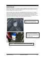
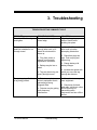
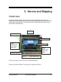
1
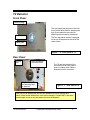
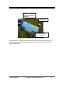
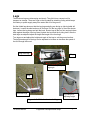
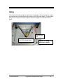
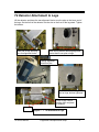
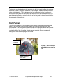
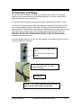
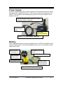
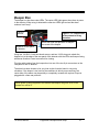
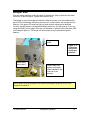
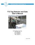
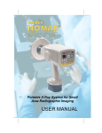
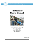
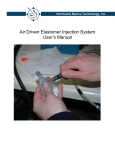
Northwest Marine Technology, Inc.
T4 Detector
for Coded Wire Tags
User’s Manual
Stand-Alone Version
Northwest Marine Technology
Shaw Island, WA
Phone: 360-468-3375
Fax:
360-468-3844
E-Mail: [email protected]
Web: www.nmt.us
September 2005
Table of Contents
Introduction.................................................................................... 3
1. Equipment Description and Setup ............................... 4
T4 Detector, stand-alone ........................................................................................... 4
T4 Detector ................................................................................................................ 5
Front Panel............................................................................................................. 5
Rear Panel ............................................................................................................. 5
Legs ........................................................................................................................... 7
Sling ........................................................................................................................... 8
T4 Detector Attachment to Legs ................................................................................ 9
Fish Funnel .............................................................................................................. 10
Connectors and Plugs.............................................................................................. 12
Power Supply........................................................................................................... 13
Battery...................................................................................................................... 13
Power Supply and Battery Setup ............................................................................. 14
Beeper Box .............................................................................................................. 15
Detection Standard .................................................................................................. 16
2. Equipment Operation................................................... 17
T4 Detector .............................................................................................................. 17
Power....................................................................................................................... 17
Beeper Box .............................................................................................................. 18
Fish Funnel .............................................................................................................. 19
Tag Detection........................................................................................................... 20
Radio Frequency Interference ................................................................................. 20
Magnetic Interference .............................................................................................. 20
3. Troubleshooting........................................................... 21
4. Maintenance ................................................................. 22
Care of the T4 Detector ........................................................................................... 22
Cleaning ............................................................................................................... 22
Disinfection........................................................................................................... 22
Disassembly............................................................................................................. 22
5. Service and Shipping................................................... 23
Transit Case............................................................................................................. 23
7. Equipment Specifications ........................................... 24
8. Contacting NMT............................................................ 25
9. Index.............................................................................. 26
T4 User’s Manual
2
Introduction
The T4 is the first and smallest of a new line of tunnel-type Coded Wire Tag (CWT)
detectors. It maintains the high sensitivity of the earlier R-Series detectors and their
ability to detect a tag in any orientation while improving upon the water resistance and
general ruggedness of those units. The T4 can operate as a stand-alone detector, with a
diverter gate, or as a Quality Control Device (QCD) for a MKIV tag injector.
The T-Series detectors are designed to plug together with one or more other system
components such as a beeper box, power supply, control box, and an automatic diverter
gate using a new unified system connector. Most components have two identical 8-pin
connectors with universal cables to interconnect them.
The T4 detector’s tunnel has inside dimensions of 2 1/4 inches (5.7cm) by 3 7/8 inches
(9.8 cm). It may be used with either the broad or the narrow dimension upright, the NMT
funnel is designed for attaching to the detector when the larger dimension is vertical.
The T4 stand-alone tag detector is supplied with an audible beeper (beeper box). The
beeper box has a power ON light and will beep and light two red LEDs when a tag is
detected.
The T4 detector may be powered from the NMT 24VDC power supply which has an
input AC voltage range from 100-250V, from an 18VDC rechargeable battery supplied
by NMT, or from a 24V standard storage battery.
The T4 is equipped with a folding set of legs as well as a watered fish funnel.
A detection standard (a dowel with a standard length coded wire tag embedded in one
end and a 1/2 length l tag in the other) is supplied with each detector. This is used for
verifying that the detector is working correctly and for determining the correct settings on
the control box.
Optional equipment available to go with the T4 detector for diverting fish, are a diverting
gate and a control box. Settings for the gate, detector and control box are made from the
control box. The control box records counts of detected tags in up to four different
groups. Using the control box it is possible to adjust the system for a variety of
situations, such as fish that move unusually fast or unusually slow.
T4 User’s Manual
Introduction
3
1. Equipment Description and Setup
T4 Detector, stand-alone
This section describes the equipment required for the T4 detector stand-alone
configuration.
Listed below is the equipment and supplies that come with the stand-alone version.
¾
¾
¾
¾
¾
¾
¾
¾
¾
¾
¾
¾
T4 detector
Leg stand with sling
Fish funnel
Beeper box with two 1/4-20X1/2 inch thumb screws and two wing nuts
18 volt modified DeWalt battery housing with power on light and low battery light
18 volt DeWalt rechargeable NiCd battery
18 volt DeWalt battery charger
24 volt power supply
One 4 foot cable
Coded wire tag detection standard
Transit case
User’s Manual
T4 Detector
Fish Funnel
Beeper Box
Adjustable legs
Battery power supply in
sling
Figure 1 - 1: T4 detector, stand-alone.
T4 User’s Manual
Equipment Description and Setup
4
T4 Detector
Front Panel
Serial number
The front panel has the entry to the fish
tunnel and a latch plate for attaching the
legs. Screw holes are provided for
attaching other accessory equipment.
Fish tunnel
The four digit serial number is stamped
on the top of the panel to the left of the
center screw.
Latch plate
Figure 1 - 2: Front panel of T4.
Rear Panel
Silicone
seal
8 pin connectors
with dust covers
Alignment blocks
for attaching legs
to detector
The T4 has two identical 8 pin
connectors on the rear panel. It
does not matter which cable is
attached to which connector.
Figure 1 - 3: Rear panel of T4.
Take care not to damage the silicone seal between the tunnel and the end
panels. Water inside the detector could cause damage. Contact NMT if the seals
are damaged in such a way that water can enter the detector.
T4 User’s Manual
Equipment Description and Setup
5
Figure 1 - 4: Artwork
on sides of detector
enclosure.
Caution label
Unit name and NMT
contact information
The sides of the T4 detector have labels naming the piece of equipment and giving
contact information to Northwest Marine Technology. The top of the detector has a
yellow Caution label.
T4 User’s Manual
Equipment Description and Setup
6
Legs
The aluminum legs are telescoping and sturdy. They fold into a compact unit for
transport or storage. There are rings on the leg stand for attaching a sling which keeps
the battery or power supply away from water and off of the ground.
Set the folded legs down so that the long legs and sling are facing up (the leg label will
be down). Loosen the side knobs on all four legs. Pull the long legs up, then the shorter
legs. Loosen the leg clamp and pull the back, shorter legs all the way out and push them
back against the edge of the leg stand, tighten the lever and the 4 prong knob. After the
back legs are adjusted adjust the height and angle of the front legs.
Turn legs over and adjust the height and angle of the legs to suit the ground surface.
The height and angle of the legs can be adjusted to increase or decrease the speed of
the fish through the tunnel.
Long front legs
Sling
Knobs for adjusting
leg angle
Sling
Extended legs
Leg clamps for
adjusting height
Figure 1 - 5: Folded and extended legs.
T4 User’s Manual
Equipment Description and Setup
7
Sling
The net sling with spring snaps at each corner is designed to hang from the four rings on
the leg stand and to hold either the 18V battery or the 24V power supply. This should be
hung in such a way as to keep the battery and power supply out of the direct flow of
water.
Ring and spring
snap
Note that the battery power
“ON” LED is lit and green
T4 User’s Manual
Figure 1 - 6: Sling
with battery supply.
Equipment Description and Setup
8
T4 Detector Attachment to Legs
Lift the detector and place the rear alignment blocks over the pins on the lower end of
the legs. Set the front of the detector into the slot on the front of the leg stand. Tighten
the latches.
Rear end of legs showing
pins for alignment blocks
Rear end of detector showing alignment
blocks that fit over pins on legs
Setting alignment
blocks on pins.
Front of detector resting in
slot on legs; latches tightened
Front of legs. Slot for
holding front end plate
of detector
latches
Figure 1 - 7: T4 attachment to Legs.
T4 User’s Manual
Equipment Description and Setup
9
The detector may be attached to the leg stand with the fish tunnel in either the vertical or
horizontal direction. If using the fish funnel, or diverter gate, the detector tunnel must be
in the vertical direction. The leg latches on the front end panel and the leg alignment
blocks on the rear panel are mounted so that the tunnel is in the vertical direction. If you
want the tunnel in the horizontal direction, then the alignment blocks and the latch bar
with latches will have to be moved to the side of the end panel so that the connectors on
the rear panel will be at the top.
Fish Funnel
The fish funnel attaches to the front panel of the detector and helps guide fish into the
tunnel. It also provides a way to inject water to help lubricate the tunnel. The water
source can be an ordinary garden hose connected to the fitting provided at the bottom of
the funnel support structure. A valve is provided near the fitting and can be used to
regulate the water flow. When the valve is properly adjusted, streams of water will
emerge from vents at the top edge of the funnel.
Tunnel
entrance
Figure 1 - 8: Fish funnel
attached to front panel of
T4.
Water emerging
from vents
T4 User’s Manual
Equipment Description and Setup
10
Clips for attaching to
detector. Two on top and
two on bottom
Near the bottom of the funnel bracket are
two locating pins that fit into two holes on
the lower front panel of the detector. Set
the bottom of the plastic funnel against
the bottom of the aluminum fish tunnel;
slide the pins into the holes.
Make sure that the clips on the top and
bottom edges of the funnel are out of the
way when positioning the funnel. Once
the funnel is in place, close the clips over
the edges of the detector end panel.
Locating pins on funnel bracket
You may need to gently squeeze
the sides of the neck of the fish
funnel to get it to go inside the
aluminum fish tunnel. The bottom
half of the funnel must fit inside of
the entrance to the detector
tunnel; the top half is designed to
line up with the tunnel entrance,
but remain just outside.
Attach a hose to the fitting on the
funnel.
Clips fastened over top edge of
detector front end panel
Hose fitting
with flow valve
Bottom of plastic funnel is inside of the
aluminum detector tunnel
Figure 1 – 9: Fish funnel attached to front end panel of T4 detector.
The clips should move easily, do not force them closed. Check that the bottom edge
and lower sides of the plastic fish funnel are inside of tunnel before tightening clips.
Be sure the locating pins on the funnel bracket are properly inserted into the holes in
the front panel.
T4 User’s Manual
Equipment Description and Setup
11
Connectors and Plugs
On any unit in the T4 system, the two 8-pin connectors are identical. The universal
cables are all the same with the two ends being identical, so it doesn’t matter which
cable gets attached to which connector.
It is important, however that in hooking units together that they are hooked in a chain.
To make sure of good electrical contact and waterproof assembly, the plug connectors
on the universal cables require a three step connecting process when inserted into a
panel connector. Rotate the plug in the connector while pushing very gently until you feel
the plug fit on the connector pins. Push the plug into the 8-pin connector as far as it
easily goes. Next turn the locking ring at least a half turn while continuing to push:
usually the plug will slide in a small additional amount. Finally, turn the locking ring
clockwise until it comes up snug.
If an 8-pin system connector is not in use then the dust cover should be closed over it for
protection against dirt and water.
8 pin connector with dust cover
open
8 pin connector with dust cover
closed
Universal cable with two 8-socket
plugs with locking rings. The cable
ends are identical.
Locking ring
Figure 1 - 10: 8-pin connectors with dust covers
and universal cable with 8 socket plugs.
T4 User’s Manual
Equipment Description and Setup
12
Power Supply
The 24VDC power supply may be used to power the T4 stand-alone detector as well as
the detector with a gate and control box. It will function from an input ranging from 100250VAC. The cord with the three pronged plug is glued into the power supply. Do not
attempt to remove it.
Plug that attaches to 8 pin connector on either
the detector, gate or control box
Cable from
power supply to
outlet
Glued plug
DO NOT REMOVE
Figure 1 - 11: Power supply with cords.
Battery
The T4 stand-alone detector may also be powered from an 18VDC rechargeable nickelcadmium DeWalt battery in a modified flashlight housing. This unit comes with a battery
charger and a cable.
Power ON LED,
Green when lit
8 pin connector
with dust cover
Rechargeable battery
Low battery LED, Red
when lit
On Off slide switch on back
Universal cable:
the plugs at each
end are identical
Figure 1 - 12: Battery 18 volt DC.
T4 User’s Manual
Equipment Description and Setup
13
Power Supply and Battery Setup
Hang the sling on the leg stand under the detector; attach each spring snap to one of the
four split rings on the leg stand. Set the power supply or battery supply in the sling.
All power supplies must be kept out of the water.
If you are using the 24V power supply, plug the cable with the 8 socket plug into the
eight pin connector on the back of the detector, gate or control box. Plug the cable with
the three prong connector into a wall outlet or an extension cord.
If you are using the 18VDC battery, be sure the battery is fully charged. It is best to
charge the battery for a full 8 hours before each use to have it work at maximum
capacity. See instructions supplied with the battery charger for further information. Plug
one end of a universal cable to the 8 pin connector on the battery face, and attach the
other end to a free connector on the detector, gate or control box.
Slide the on/off switch up to the on position; the green Power ON Led should light up.
The slide switch is on the back. If the battery is low, the red Low Battery LED will come
on. Always change or charge the battery as soon as the red Low Power LED comes on.
With just the detector and beeper box, a fully charged battery should last 30 hours. As
the battery gets old, or if not properly charged, the battery may not last as long.
CAUTION: Change the battery as soon as the red LOW Battery LED comes on.
T4 User’s Manual
Equipment Description and Setup
14
Beeper Box
The beeper box has three clear LEDs. The center LED lights green when there is power
to the detector. When a tag is detected the other two LEDs light red and the alarm
makes a loud “beep”.
Cable to
detector
Figure 1 - 13: Beeper Box
at the moment of a tag
detection.
Alarm with foam ear protector to dampen
the sound of the beeper
Attached to rear panel
of detector
Using two 1/4-20X1/2 inch hex thumb screws, and two 1/4-20 wing nuts, attach the
beeper box to the edge of the rear panel of the detector with the LEDs and beeper facing
whichever direction is most convenient for viewing.
Plug the cable coming from the beeper box into one of the two 8 pin connectors on the
rear panel of the T4 detector.
The alarm has been chosen to be very loud so that it can be heard in very noisy
situations. If the beeper is too loud for the conditions in which you are working, the
center hole of the alarm may be partially or completely covered with a piece of tape or
plugged with a foam ear protector.
When power is being supplied to the detector and beeper the green LED on the
beeper box will be lit.
T4 User’s Manual
Equipment Description and Setup
15
Detection Standard
The detection standard is a wooden stick which has a standard length CWT imbedded in
one end and a 1/2 length tag imbedded in the other end. A single ring around the end of
the stick indicates the end with a 1/2 length tag and the end with two rings indicates the
standard tag. Pass the detection standard through the tunnel to verify that the detector is
detecting tags and to determine the range of speeds at which a tag is detected.
The detection standard
Single ring at end indicates a
½ length Coded Wire Tag
Two rings at end indicate a Standard
length Coded Wire Tag
Figure 1 - 14: Detection Standard.
T4 User’s Manual
Equipment Description and Setup
16
2. Equipment Operation
T4 Detector
Power
To power the detector with the 24V power supply, attach the plug from the power supply
cable to one of the 8-pin connectors on the rear panel of the detector. Make certain that
the coupling ring on the plug is screwed tight to the connector.
Plug the three prong plug cable into a wall outlet or extension cord. Keep the power
supply dry.
If you are using the 18VDC battery instead of the power supply to power the detector
read about charging the battery in Section 1. Use the cable with an 8 pin plug on each
end. Attach one end to the face plate of the battery housing and the other end to one of
the connectors on the rear panel of the detector. Slide the on/off switch up to the on
position; the green Power ON Led should light up. The slide switch is on the back. If the
battery is low, the red Low Battery LED will come on. With a fully charged battery the
detector and beeper should operate for at least 30 hours.
Once power is connected to the detector it takes about 20 seconds before the
detector will detect a tag and sound the beeper.
Green Power ON LED is lit.
Cable attached to battery
Figure 2 - 1: 18VDC battery for T4
T4 User’s Manual
Equipment Operation
17
Beeper Box
With the beeper attached to the rear panel of the detector, plug its cable into the other
connector on the rear panel. Tighten the connector ring.
The beeper is powered through the detector. When the power is on to the detector the
green LED on the beeper will light up as soon as it is connected to the rear panel of the
detector. If the green LED does not light up check that the cables are all attached
correctly, that the battery is charged and battery switch is in the ON position. If you are
using the 24VDC power supply, then the only indication of power is when the green LED
on the beeper lights up. The beeper will sound when a tag is passed through the
detector.
Beeper box
cable
Figure 2 - 2:
T4 detector
with power
and beeper
attached
Power cable
from battery
Power cable from
battery and beeper
cable attached to the
rear end of the
detector.
When power is being supplied to the detector and beeper the green LED on the
beeper box will be lit.
T4 User’s Manual
Equipment Operation
18
Fish Funnel
Once you have power to the detector, hook up a garden hose to the hose connector on
the fish funnel. Adjust the water flow with the black handled valve. Water will come out
around the upper front edges of the funnel.
Adjust the water flow so that the fish are sliding easily through the tunnel. The water
coming out of the back of the detector should be hitting the ground at about 12 inches
from the end of the tunnel. If the water flow is not adequate then the fish will go too
slowly through the detector and a single tag may be detected twice. For starting, set the
leg heights so that the top edge of the funnel is parallel to the ground.
Good water flow in the funnel.
The tunnel has a fast moving
stream of water going through it.
Water is coming out the back
edge of the tunnel and hitting the
floor at about 12 inches from the
end of the tunnel.
Figure 2 - 3: Water flow through the funnel, tunnel and gate.
T4 User’s Manual
Equipment Operation
19
Tag Detection
Once everything is hooked up, pass the detection standard through the tunnel several
times to determine that tags are being detected. Move the tag through at the rate you
think your tagged specimens will be going to verify that the detector will detect a tag at
that speed. Verify this speed by putting some test fish through the detector. Be sure the
water is on and adjust the leg angle and water flow until the fish pass through at a rate
such that the beeper always goes off when a tagged fish passes through the center of
the tunnel. It is suggested that you start with the top edge of the funnel parallel to the
ground.
Radio Frequency Interference
The T4 tag detector has been designed to withstand radio frequency interference from
hand held radio transmitters and cell phones kept at a moderate distance from the units.
However if a radio transmitter is operated closer than six feet (2 meters) it may set off
the detector and give false positive detections.
Magnetic Interference
The T4 detector should be set up away from equipment that generates strong magnetic
fields such as large motors because these magnetic fields may cause false positive
detections. If this happens, move the detector further away from the source of the
magnetic field.
T4 User’s Manual
Equipment Operation
20
3. Troubleshooting
TROUBLESHOOTING SUMMARY TABLE
PROBLEM
POSSIBLE CAUSES
SOLUTION
Funnel is difficult to align
and tighten
Funnel neck is caught on
tunnel edge
Align locating pins, squeeze
sides of funnel while
pushing into place.
Beeper doesn’t sound when
detection standard is run
through tunnel
1. Haven’t waited long
enough after hook up of
power for electronics to
warm up.
1. Wait 15 – 20 seconds
after hook up before
attempting a detection.
2. Plug from power or
beeper is not properly
tightened to connector.
3. Battery may be low or
dead.
4. Tag may be moving too
slowly through tunnel.
Beeper is going off without
a tag being present
1. Detector may be too
close to equipment that is
generating a strong
magnetic field.
2. Detector may be getting
radio frequency
interference.
T4 User’s Manual
Troubleshooting
2. Check that plugs are
tight. Push on plug and
tighten ring.
3. Charge battery with
battery charger.
4. Increase the speed with
which you move the tag
through the detector.
1. Move detector away
from equipment.
2. Check area for hand
held radio, cell phone, other
device that may be
transmitting radio
frequencies and turn off the
device.
21
4. Maintenance
Care of the T4 Detector
The detector and beeper are designed to be waterproof, however care must be taken
not to damage the silicone seals around the ends of the fish tunnel
Do not drop the detector; internal parts could be damaged.
Cleaning
At the end of each session, unplug the power and beeper cables from the back of the
detector and put the caps over the connectors before washing.
Remove the 24V power supply or 18V battery from the sling under the detector. Wipe
dry if they are wet. Do not spray them with the hose.
Wash the detector and fish funnel thoroughly with water or soap and water. Use a soft
brush and or sponge to remove scales and slime. DO NOT USE A HIGH PRESSURE
HOSE. Use normal water pressure for washing the detector.
Disinfection
To disinfect the equipment we recommend using a household bleach (which is a 5%
solution hypochlorite) and diluting it 1part bleach to 25 parts water for a final solution of
200ppm hypochlorite and leaving it on for a minimum of 10 minutes. Rinse the
equipment well with fresh water (not pond water) after disinfection.
Disassembly
Prior to moving or shipping the T4 detector, unplug the power and beeper cables.
Remove the beeper from the rear panel and the fish funnel from the front panel. Remove
the detector from the leg stand and fold the legs. The sling may be left in place.
T4 User’s Manual
Maintenance
22
5. Service and Shipping
Transit Case
The transit case has a foam interior with cut outs for the detector and some of the
accessories. Set the detector into the foam so that the alignment blocks are to the center
of the case as shown below. The accessories will be further packed in bubble wrap to
protect them during shipping.
Detector
Alignment blocks
User’s Manual
Battery
housing, 24V
power supply,
beeper box
Removable divider
Battery
charger, 18V
battery and
cable
Detection standard
Figure 5 - 1: Packed transit case
The legs with sling and fish funnel are packaged separately.
Please call Northwest Marine Technology for shipping instructions.
T4 User’s Manual
Service and Shipping
23
7. Equipment Specifications
T4 Detector:
Dimensions: 22” (55.9cm) long x 11” (27.9cm) high x 11” (27.9cm) high
Weight: 26 pounds (11.8 kg)
Legs:
Dimensions: folded: 22.5” (57.2cm) long x 13.75” (34.9cm) wide x 4.5” (11.4
cm) high
Dimensions: Legs extended: Front 37” (94 cm), Back 27.5” (69.8cm)
Weight: 13 pounds (5.9 kg)
Fish Funnel:
Dimensions: 11.5” (29.2 cm) high x 11.5” (29.2 cm) wide x 15” (38.1 cm) deep
Weight: 4.5 pounds (2.0kg)
Beeper Box mounted on plate:
Dimensions: 4 inches (10.2 cm) long x 3.375” (8.6cm) wide x 2.37” (6.0cm) deep
includes nuts
Weight: .5 pounds (.23kg)
NMT 24V Power supply:
Input from 100-250VAC, 50/60Hz, 1.5A-0.6A
Dimensions: 6.5” (16.5cm) long x 3.6” (9.2cm) wide x 2.25” (5.7) cm deep
Weight: 3.25 pounds (1.4kg)
Modified flashlight housing with battery:
Weight: 3.5 pounds (1.6 kg)
Battery: DeWalt rechargeable NiCd 18V, XRP
Battery Charger: DeWalt DW9116 7.2V-18V
Transit Case:
Dimensions: 27” (68.6cm) long x 22” (55.9 cm) wide x 16.5” (41.9 cm) high
Weight: 25 pounds (11.3kg)
If you have questions regarding the operation of the T4 detector or accessory
equipment, call Northwest Marine Technology at 360-468-3375 or e-mail
[email protected].
T4 User’s Manual
Equipment Specifications
24
8. Contacting NMT
NMT strives to provide the highest quality tagging systems for research and
management. We offer free consultation on the suitability of available methods for
specific purposes.
Corporate Office
For information on prices, delivery times, and for assistance on any questions or
problems relating to our equipment for use in any location please contact our main
office:
Northwest Marine Technology
Corporate Office
P.O. Box 427, Ben Nevis Loop Road
Shaw Island, WA 98286
U.S.A.
Telephone:
E-mail:
Support:
Web Site:
(360) 468-3375, FAX: (360) 468-3844
[email protected]
[email protected]
www.nmt.us
Biological Services
For questions relating to the suitability of methods for various species and life stages,
please contact our biological services office:
Northwest Marine Technology
Biological Services
955 Malin Lane SW
Tumwater, WA 98501
U.S.A.
Telephone: (360) 596-9400, FAX: (360) 596-9405
Email: [email protected]
T4 User’s Manual
Contacting NMT
25
9. Index
Battery
description ...................................... 13
Beeper Box)
description and setup ..................... 15
Beeper Box, operation ....................... 18
Cell Phone Interference ..................... 20
Cleaning ............................................. 22
Connectors and Plugs
description and setup ..................... 12
Contacting NMT ................................. 25
Detection Standard
description ...................................... 16
Disassembly....................................... 22
Disinfection......................................... 22
Equipment
description and setup ....................... 4
list ..................................................... 4
operation......................................... 17
specifications .................................. 24
Fish Funnel
description and setup ..................... 10
operation......................................... 19
Front panel ........................................... 5
T4 User’s Manual
Legs
description and setup........................ 7
Magnetic Interference......................... 20
Maintenance ....................................... 22
Power Supply
description....................................... 13
Power Supply and Battery
setup ............................................... 14
Radio Frequency Interference ............ 20
Rear panel ............................................ 5
Service................................................ 23
Shipping.............................................. 23
Sling
description......................................... 8
Stand-alone
equipment and supplies .................... 4
T4 Detector
description......................................... 5
operation ......................................... 17
power .............................................. 17
setup ................................................. 9
Tag Detection ..................................... 20
Transit Case ....................................... 23
Troubleshooting.................................. 21
Index
26