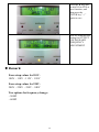
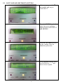
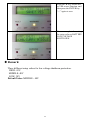
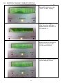
1
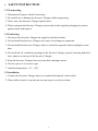
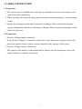
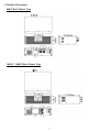
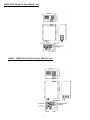
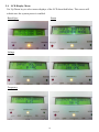
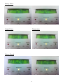
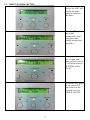
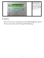
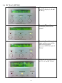
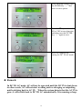
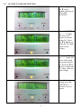
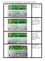
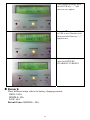
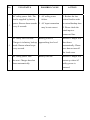
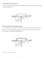
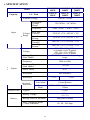
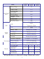
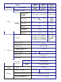
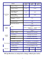
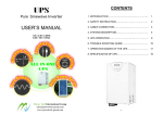
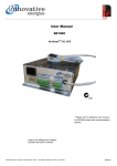
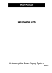
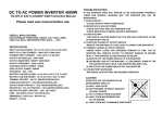
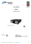
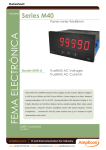
USER MANUAL Innovative Energies Ltd . 1 Heremai Street, Henderson NZ . Tel: +64 9 835 0700 . [email protected] . www.innovative.co.nz 1 CONTENTS 1. INTRODUCTION .............................. 1 2. SAFTY INSTRUCTION..................... 3 3. CABLE CONNECTION..................... 4 4. SYSTEM DESCRIPTION................... 5 5. OPERATION ....................................... 9 6. TROUBLE SHOOTING GUIDE......... 25 7. OPERATION MODES ..............…….. 27 8. SPECIFICATION..................…........... 29 1. INTRODUCTION 1.1 General Description The Inverter/ Charger (solar charge controller as optional), a powerful all-in-one solution, delivers unsurpassed clean true sine wave output power and combines this with a selectable multistage battery charging current. Applicable for any kind of loads such as air conditioner, home appliances, consumer electronic and office equipments. This series features a durable&continuous 24 operation. The built-in 5-stage intelligent charger automatically charges any type of batteries without the risk of overcharge. The compact&modular design makes utility interactive installations easier and more cost effective. It is a high quality product that offers the best price/performance ratio in the industry. 1.2 Key features 1. Multiple microprocessor design base. 2. Compatible with both linear&non-linear load. 3. Stronger charger to support batteries of 500AH up. 4. 24 hours operation on the inverter. 5. DC start and automatic self-diagnostic function. 6. THD less than 3%. 7. High efficiency design to save electricity. 8. Low heat dissipation in long time operation 9. Design to operate under harsh environment 10. 3U 19” Rack Mount or WALL Mounted design 11. DC priority or AC priority selectable 1.3 Important Notices 1. Read instructions carefully before operating the Inverter/ Charger. 2. Inverter/ Charger power connect instruction should be followed. 3. Please don‘t open the case to prevent danger. 4. Maximum solar charging current: 50AMP 5. Retain the load within the rating of Inverter/ Charger to prevent faults. 6. Keep the Inverter/ Charger clean and dry. 1 2. SAFTY INSTRUCTION 2.1 Transporting 1. Disconnect all power cables if necessary. 2. Be careful not to damage the Inverter/ Charger while transporting. 3. Don‘t move the Inverter/ Charger upside down. 4. Please transport the Inverter/ Charger system only in the original packaging (to protect against shock and impact). 2.2 Positioning 1. Do not put the Inverter/ Charger on rugged or declined surface. 2. Do not install the Inverter/ Charger near water or in damp environments. 3. Do not install the Inverter/ Charger where it would be exposed to direct sunlight or near heat. 4. Do not block off ventilation openings in the Inverter/ Charger system’s housing and don’t leave objects on the top of the Inverter/ Charger. 5. Keep the Inverter/ Charger far away from heat emitting sources. 6. Do not expose it to corrosive gas. 7. Ambient temperature : 0℃ - 40℃ 2.3 Installation 1. Connect the Inverter/ Charger only to an earthed shockproof socket outlet. 2. Place cables in such a way that no one can step on or trip over them. 2 2.4 Operation 1. Do not disconnect the mains cable on the Inverter/ Charger or the building wiring socket outlet during operations since this would cancel the protective earthing of the Inverter/ Charger and of all connected loads. 2. Ensure that no fluids or other foreign objects can enter the Inverter/ Charger system. 2.5 Maintenance and Service 1. Caution - risk of electric shock. Even after the unit is disconnected from the mains power supply (building wiring socket outlet), components inside the Inverter/ Charger are still connected to the battery and are still electrically live and dangerous. Before carrying out any kind of servicing and/or maintenance, disconnect the batteries and verify that no current is present. 2. Batteries may cause electric shock and have a high short-circuit current. Please take the precautionary measures specified below and any other measures necessary when working with batteries: - remove wristwatches, rings and other metal objects - use only tools with insulated grips and handles. 3 3. CABLE CONNECTION 3.1 Inspection 1. The system may be installed and wired only by qualified electricians in accordance with applicable safety regulations. 2. When installing the electrical wiring, please note the nominal amperage of your incoming feeder. 3. Inspect the packaging carton and its contents for damage. Please inform the transport agency immediately should you find signs of damage. Please keep the packaging in a safe place for future use. 3.2 Connection 1. Inverter/ Charger Input Connection If the Inverter/ Charger is connected via the power cord, please use a proper socket with protection against electric current, and pay attention to the capacity of the socket. 2. Inverter/ Charger Output Connection The output of this model is with terminal block. Simply wire the load power cord to the output terminal to complete connection. 4 4. SYSTEM DESCRIPTION 4.1 Front Panel Description for LCD Model 1. LCD Display: This indicates the Inverter/ Charger operation information, including UPS status, input/output voltage, input/output frequency, battery voltage, battery capacity left, output load, inside temperature, and the times of history events. 2. Up-key: Use to select upward the Inverter/ Charger status on LCD Display. 3. Down-key: Use to select downward the Inverter/ Charger status on LCD Display. Beside, press it simultaneously with the Up-key to switch off the Inverter/ Charger. 4. Enter-Key: It is pressed with the Down-key to turn on the Inverter/ Charger. In battery operation mode, press it with Up-key at the same time to disable the buzzer. Beside, it is pressed to confirm and enter the item selected. 5. Fault LED (red): To indicate the Inverter/ Charger is in fault condition because of inverter shutdown or over-temperature. 6. Warning LED (yellow): To indicate the Inverter/ Charger is in the status of overload, bypass and battery back-up. 7. Normal LED (green): To indicate the Inverter/ Charger is operating normally. 8. ON/TEST/MUTE key: It should be pressed with the control key simultaneously to switch on Inverter/ Charger, do auto-test in normal AC mode and turn off the buzzer in battery operation. 5 4.2 Outline Description 800W Rack Mount Type 1600W / 2400W Rack Mount Type 6 800W Wall Mounted Type 1600W / 2400W Wall Mounted Type 4000W / 6000W / 8000W Wall Mounted Type 7 800W Wall Mounted Type (Black case) 1600W / 2400W Wall Mounted Type (Black Case) 8 5. OPERATION 5.1 Check Prior to Start Up 1. Ensure the Inverter/ Charger is in a suitable positioning. 2. Check input cord is secured. 3. Make sure the load is disconnected or in the “OFF” position. 4. Check if input voltage meets the Inverter/ Charger rating required. 5.2 Storage Instruction Disconnect input power in rear panel if you will not use it for long period. If the Inverter/ Charger is stored over 3 months, please keep supplying power to the Inverter/ Charger for at least 24 hours to ensure battery fully recharged. 5.3 Operation Procedure for LCD Model Please follow the instructions below for Inverter/ Charger operation. 1. Once the AC source is connected, the LCD Display shall light up immediately to display first the main menu of greeting context and the Normal LED is blinking to indicate ready to switch on the inverter. 2. By pressing the Enter-key and the Down-key simultaneously for 3 seconds, the Inverter/ Charger will start up after two beeps and Normal LED lights up to indicate the power is from its inverter to the load. 3. When the Down-key and the Up-key are pressed simultaneously for 3 seconds, the inverter will be turned off after two beeps and the Inverter/ Charger is on the standby status (LCD display illuminates and Normal LED is blinking) until AC source is disconnected. 9 5.4 LCD Display Menu Use Up/Down key to select menu-displays of the LCD described below. This screen will refresh once the system power is enabled. Rated Spec Status Voltage Frequency 10 Battery Status Output Power Temperature History Record 11 5.5 GREEN POWER SETTING After the startup screen, the LCD will display the main menu as shown in the photo. Press the ▼ key in the middle continuously until seeing the same display as shown in the photo. Then press the enter key at right, and there will be a cursor (→) shown between SETTING and AC TO AC Press enter key again so the cursor will move down to the position between GREEN and OFF. 12 Press the ▼ key in the middle once, the LCD Display shall now display GREEN →ON 30sec Press the enter key at right again, and the cursor shall move to the right and now pointing 30sec. There are 4 options (15sec, 30sec, 45sec, 60sec) for how often to run the detection. After completing the setting, press the enter key at right. The LCD Display shall display “FUNCTION SETTING SAVE? NO” as shown in photo. Press the ▼ key in the middle, the text “NO” shall now become “YES”, then press the enter key again to confirm the setting. 13 The same screen as shown in the photo shall be displaying, and the inverter will automatically run the detection on GREEN POWER every 30 sec. Remark: When AC IN source is connected, the Normal LED will light up; when AC IN source is not connected, the Warning LED will light up. 14 5.6 DC TO AC SETTING After startup, we can change the LCD display by the ▲ & ▼ key Press the ▼ key till you see the display shown in the picture. Press the “Enter” key < at right, and then you will be able to see an arrow between SETTING and AC TO AC Press the ▼ key, and switch AC TO AC to DC TO AC 15 After finishing setting, press the ENTER key “<” and move to save option. Press the ▼ key and switch NO to YES at save function, and then press the ENTER key “<” again to save Now we complete the setting for DC TO AC mode Remark: In DC TO AC mode, AC will not be operated until the DC IN is shut down. in other words, AC will not start working such as charging or outputting until switching back to AC IN. When the system detects that the AC IN is gone, it will switch back to DC TO AC automatically. It is running as loop. 16 5.7 AC INPUT VOLTAGE SETTING After startup, press the ▼ in the middle, and stop at “I/P VOLT SETTING” Press the ENTER key “<” at right, the arrow will appear at bottom before LO. Press the ▼ & ▲ key to adjust the AC input value for low voltage Press the ENTER key “<” again, the arrow will switch the position before HI. Press the ▼ & ▲ key to adjust the AC input value for high voltage After finishing setting, press the ENTER key “<” and move to save option. 17 Press the ▼ key, switch NO to YES at save function, and then press the ENTER key “<” again to save Now we complete the setting for adjusting the value to AC INPUT HIGH/LOW VOLTAGE Remark: Low voltage 110V system – Range: 60V~100V 220V system – Range 120V~200V High voltage 110V system –Range: 125V~140V 220V system –Range 250V~280V 18 5.8 OUTPUT VOLTAGE AND FREQUENCY ADJUSTMENT SETTING After startup, press the ▼ in the middle, and stop at “VOLT/FREQ SET” Press the ENTER key “<” at right, the arrow will appear at bottom before 100 VAC. Press the ▼ & ▲ key to adjust the output voltage Press the ENTER key “<” again, the arrow will switch the position before 50HZ(or 60HZ). Press the ▼ & ▲ key to adjust the output frequency After finishing setting, press the ENTER key “<” and move to save option. 19 Press the ▼ key and switch NO to YES at save function, and then press the ENTER key “<” again to save Now we complete the setting for OUTPUT VOLTAGE AND FREQUENCY ADJUSTMENT Remark: Four setup values for 110V– 100V、110V、115V、120V Four setup values for 220V– 200V、220V、230V、240V Two options for frequency change: - 50HZ - 60HZ 20 5.9 LOW VOLTAGE SHUTDOWN SETTING After startup, press the ▼ in the middle, and stop at “BAT.SHUT” Press the ENTER key “<” at right, the arrow will then appear between BAT.SHUT and MIDDLE Press the ▼ & ▲ key to set up the voltage value for shutdown protection After finishing setting, press the ENTER key “<” and move to save option. 21 Press the ▼ key, switch NO to YES at save function, and then press the ENTER key “<” again to save Now we complete the setting for setup value to BATTERY LOW VOLTAGE SHUTDOWN Remark: Three different setup values for low voltage shutdown protection. HIGH: 42V. MIDDLE: 40V LOW: 38V Default Value: MIDDLE - 40V 22 5.10 BATTERY CHARGE CURRENT SETTING After startup, press the ▼ in the middle, and stop at the “CHG.. CURR” display Press the ENTER key “<” at right, the arrow will then appear between BAT.SHUT and MIDDLE Press the ENTER key “<” again, the arrow will switch to bottom between CHG. CURR and MIDDLE Press the ▼ & ▲ key to set up the charging current 23 After finishing setting, press the ENTER key “<” and move to save option. Press the ▼ key, switch NO to YES at save function, and then press the Enter key “<” again to save Now we complete the setup value for BATTERY CHARGING CURRENT Remark: Three different setup values for battery charging current. HIGH: 100A. MIDDLE: 80A LOW: 60A Default Value: MIDDLE - 80A 24 6. TROUBLE SHOOTING GUIDE 6.1 For LCD Model The following guideline may be helpful for basic problem solving. No. UPS STATUS POSSIBLE CAUSE AC utility power is normal. 1. Charger PCB is Inverter/ Charger is 1 running normally, but fault 1.Replace the charger PCB. 2. Fan is damaged. 2.Replace the fan. 3. Unknown 3.Restart AC utility power is normal Overload Please reduce the but Inverter/ Charger is 100%< load< 125% critical load to <100%. AC utility power is normal. Overload Please reduce the Warning LED does not 125%< load<150% critical load to <100%. AC utility power is normal. Overload Please reduce the Warning LED lits up and 150%< load critical load to <100%. LED lits up. Buzzer beeps continuously. 2 damaged. ACTION overloaded. Warning LED lits up and buzzer beeps per second. 3 4 fade out and buzzer beeps per 0.5 second. buzzer beeps continuously. 25 No. UPS STATUS AC utility power fails .The load is supplied by battery 5 POSSIBLE CAUSE 1. AC utility power failure. power. Buzzer alarm sounds 2. AC input connection every 4 seconds. may be not correct. ACTION 1. Reduce the less critical load in order to extend backup time. 2. Please check the rated input or connected line. AC utility fails. Inverter/ 6 Battery power is Inverter/ Charger will Charger is in battery backup approaching low level. shut down mode. Buzzer alarm beeps automatically. Please every second. save data or turn off the loads soon. AC utility power fails. 7 Battery runs out Inverter/ Charger will Inverter/ Charger has shut restart up when AC down automatically. utility power is restored. 26 7. OPERATION MODES 7.1 Inverter/ Charger System Block Diagram 7.2 Normal Operation (AC Priority) There are two main loops when AC utility is normal: the AC loop and the battery charging loop. The AC output power comes from AC utility input and passes through static switch to support power to load. The battery charging voltage comes from AC utility input and converted by AC/DC charger to support battery-charging power. 7.3 AC Utility Failure (Battery Mode) The AC output comes from battery, passing through DC/AC inverter and static switch within the battery backup time. 27 7.4 Normal Operation (DC Priority) The AC output comes from battery, passing through DC/AC inverter and static switch within the battery backup time. 7.5 DC Utility Failure (Out-Of-Battery Mode) The AC output power comes from AC utility input and passes through static switch to support power to load. The battery charging voltage comes from AC utility input and converted by AC/DC charger to support battery-charging power. **please refer to P.17 -5.6 DC to AC SETTING 28 8. SPECIFICATION INVERTER INVERTER INVERTER 800W 1600W 2400W 1.2KVA / 2.4KVA / 3.6KVA / 800W 1600W 2400W Model Capacity VA / Watt Nominal Voltage 220Vac; 110Vac Acceptable Voltage Range Input Voltage Range 120-280Vac ; 60-140Vac Frequency 50Hz / 60Hz Line Low Transfer Line Low Return Line High Transfer Line High Return 120VAC ± 2% ; 60VAC ± 2% 130VAC ± 2% ; 65VAC ± 2% 280VAC ± 2% ; 140VAC ± 2% 260VAC ± 2% ; 130VAC ± 2% 200 / 220 / 230 / 240Vac re-settable via LCD panel) 100 / 110 / 115 / 120Vac re-settable via LCD panel) < 3% RMS for entire battery voltage range Voltage Voltage Regulation (Batt. Mode) Frequency Output 50Hz or 60Hz Frequency Regulation (Batt. Mode) ±0.1Hz Power Factor 0.67 Waveform Pure Sinewave Effiecincy Overload Protection Transfer Time Battery ( 45Hz - 70Hz) > 75% > 80% Line Mode Circuit Breaker Battery Mode 110% ~ 150% for 30 sec. , >150% for 200ms Typical < 8 ms. Battery Voltage 24Vdc (20~32) Backup Time (at full load) long time available Max. Charging Current (3 steps selectable) 60 / 80 / 100 Amp 29 INVERTER INVERTER INVERTER 800W 1600W 2400W Model Solar Charge (SLU) Display LCD Battery Voltage 24V Charge Vlotage 27.7V Solar Maximum Peak Voltage 50.0V Solar Charge Working Voltage Maximum Charging Current 24.0V Polarity Protect YES Back Flow Protect YES 50A UPS status, I/P&O/P Voltage Frequency, Load%, Battery Voltage & %, Charge current, Temperature, Model Normal (Green), Warning (Yellow), Fault (Red) LCD LED Battery Audible Alarm Mode Beeping every 4 seconds Low Battery Beeping every second UPS Fault Beeping Continuously Overload Beeping twice per second Operation Temperature Environment 0-40 degree C; 32-104 degree F Relative Humidity 0-95% non-dondensing Audible Noise Less than 55dBA (at 1M) Net Weigh (Kgs) Physical 14 21 23 (WxHxD)mm Black Case 298*400*155 298*450*150 298*450*150 (WxHxD)mm Rack Mount 440*132*290 440*132*360 440*132*360 (WxHxD)mm Wall Mounted 298*400*150 298*450*190 298*450*190 Specifications are subjected to change without prior notice. 30 INVERTER INVERTER INVERTER 4000W 6000W 8000W 5KVA / 6KVA / 8KVA / 4000W 6000W 8000W Model Capacity VA / Watt Nominal Voltage Input Voltage Range 220Vac; 110Vac 220Vac only Acceptable Voltage Range 120-280Vac ; 60-140Vac 120-280Vac Frequency 50Hz / 60Hz ( 45Hz 70Hz) Line Low Transfer Line Low Return Line High Transfer Line High Return 120VAC ± 2% ; 60VAC ± 2% 130VAC ± 2% ; 65VAC ± 2% 280VAC ± 2% ; 140VAC ± 2% 260VAC ± 2% ; 130VAC ± 2% 200 / 220 / 230 / 240Vac re-settable via LCD panel) 100 / 110 / 115 / 120Vac re-settable via LCD panel) Voltage Voltage Regulation (Batt. Mode) 50Hz or 60Hz Frequency Regulation (Batt. Mode) ±0.1Hz Power Factor Transfer Time 0.8 Pure Sinewave Effiecincy > 80% Line Mode Circuit Breaker Battery Mode 110% ~ 150% for 30 sec. >150% for 200ms Typical < 8 ms. 24Vdc (20~32) Battery Voltage Battery 1.0 Waveform Overload Protection 200 / 220 / 230 / 240Vac re-settable via LCD panel < 3% RMS for entire battery voltage range Frequency Output 50Hz / 60Hz ( 45Hz 70Hz) 120VAC ± 2% 130VAC ± 2% 280VAC ± 2% 260VAC ± 2% 48Vdc (42~62) Backup Time (at full load) long time available Max. Charging Current (3 steps selectable) 60 / 80 / 100 Amp 31 INVERTER INVERTER INVERTER 4000W 6000W 8000W Model Solar Charge (SLU) Display LCD Battery Voltage 24V 48V Charge Vlotage 27.7V 55.2V Solar Maximum Peak Voltage 50.0V 100V Solar Charge Working Voltage 24.0V 44.0V Maximum Charging Current 50A Polarity Protect YES Back Flow Protect YES UPS status, I/P&O/P Voltage Frequency, Load%, Battery Voltage & %, Charge current, Temperature, Model Normal (Green), Warning (Yellow), Fault (Red) LCD LED Battery Audible Alarm Mode Beeping every 4 seconds Low Battery Beeping every second UPS Fault Beeping Continuously Overload Beeping twice per second Operation Temperature Environment 0-40 degree C; 32-104 degree F Relative Humidity 0-95% non-dondensing Audible Noise Less than 55dBA (at 1M) Net Weigh (Kgs) Physical 49.2Kg (WxHxD)mm Wall Mounted 51.4Kg 55Kg 415*600*260 415*600*260 415*600*260 Specifications are subjected to change without prior notice. 32