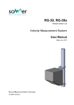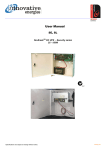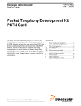
1
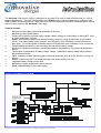
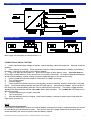
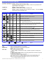
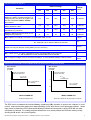
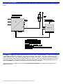
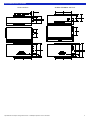
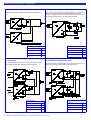
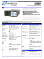
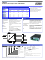
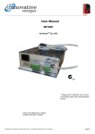
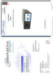
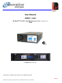
User Manual
SR250i….LAN+
No-BreakTM DC UPS - with Ethernet port (SNMP - firmware va11)
250W
2 x SR250 fitted in 2U rack
Please refer to separate user manual for full SNMP instructions
08/06/15
Specifications are subject to change without notice. No liability accepted for errors or omissions.
1
Safety
The user is responsible for ensuring that input and output wiring segregation complies with local standards and that in
the use of the equipment, access is confined to operators and service personnel. A low resistance earth connection is
essential to ensure safety and additionally, satisfactory EMI suppression (see below).
HAZARDOUS VOLTAGES EXIST WITHIN A POWER SUPPLY ENCLOSURE AND ANY REPAIRS MUST
BE CARRIED OUT BY A QUALIFIED SERVICEPERSON.
Electrical Strength Tests
Components within the power supply responsible for providing the safety barrier between input and output are constructed to provide electrical isolation as required by the relevant standard. However EMI filtering components could be damaged as result of excessively long high voltage tests between input, output and ground. Please contact our technicians
for advice regarding electric strength tests.
Earth Leakage
Where fitted, EMI suppression circuits cause earth leakage currents which may be to a maximum of 3.5mA.
Ventilation
High operating temperature is a major cause of power supply failures, for example, a 10oC rise in the operating temperature of a component will halve its expected life. Therefore always ensure that there is adequate ventilation for the
equipment. Batteries in particular suffer shortened lifetimes if subjected to high ambient temperatures.
Water / Dust
Every effort must be made in the installation to minimise the risk of ingress of water or dust. Water will almost always
cause instant failure. The effects of dust are slower in causing failure of electronic equipment but all electrical equipment should be cleaned free of any dust accumulation at regular intervals.
Electromagnetic Interference (EMI)
Switching power supplies and converters inherently generate electrical noise. All wiring should be as short as practicable and segregated from all equipment wiring which is sensitive to EMI. Residual noise can be reduced by looping DC
wiring through ferrite cores (sleeves). These are most effective as close to the power supply as possible and as many
turns of the wire taken through the core (+ and - in the same direction) as the core will accommodate.
External fuse protection
Fuses or circuit breakers must be used in all battery circuits to protect against short circuits. External fuses should be
used for power supplies/ chargers even though they are usually internally protected.
Connection polarity
It is critical to check the polarity carefully when connecting DC devices. Some Innovative Energies models have nondestructive reverse polarity protection but usually a reverse polarity connection will result in a blown fuse or serious damage to the device.
Glossary of terms used in our user manuals
PSU = power supply unit
BCT = battery condition test
ECB = electronic circuit breaker
ELVD = electronic low voltage disconnect
RPP = reverse polarity protection
EMI = electromagnetic interference
SNMP = Simple Network Management
Protocol
LAN = local area network
DOD = depth of discharge
Specifications are subject to change without notice. No liability accepted for errors or omissions.
2
The No-Break™ DC power supply is designed to provide DC power to lead acid batteries for critical
back up applications. This user manual refers to the SR250i version with an Ethernet port configured with
SNMP network monitoring protocol. Note that some of the more general information contained in this manual
refers to other models in the No-Break™ DC range
Features include:
♦
♦
♦
♦
♦
♦
♦
♦
♦
♦
♦
♦
Monitoring of the battery status and availability at all times
Monitoring of input power status
Continuous monitoring of power supply voltage, battery voltage on mains failure or during BCT, power supply and battery currents
Battery overcurrent protection and reverse polarity connection, using an electronic circuit breaker
(ECB). With input (mains) power present, the ECB acts to limit the battery current but does not
latch open. If no mains power is present then the ECB will latch open on battery circuit overcurrent.
Deep discharge protection by disconnecting the load at low battery voltage.
Monitoring of ambient temperature (usually temperature near batteries) using external temperature
sensor
Temperature compensation of battery charge voltage - essential for battery health where ambient
temperatures fluctuate.
Alarm contacts to enable interfacing with monitoring equipment such as PLCs, SCADA, security, telemetry
Battery condition test (BCT) at preset intervals or as determined by the user.
Adjustable battery charge current limit
Monitoring of power supply and network settings
SNMP traps available for user data logging
No-Break™ SYSTEM BLOCK DIAGRAM
Ethernet port
Toggle output
Specifications are subject to change without notice. No liability accepted for errors or omissions.
3
CONNECTION DIAGRAM
REAR PANEL LAYOUT
Refer to page 7 for description of control terminals 1 - 4.
CONNECTION & INITIAL TESTING
1
Check input and output voltages of system, ensure that they match the equipment. All loads should be
isolated.
2
Check polarity of all wiring. Place temperature sensor probe on the batteries or ideally on the battery
terminals. Connect the LAN port to the Ethernet network.
3
Plug in ac input and turn power on. Both LEDs will light up after approx. 4 sec, “BATTERY SYS OK”
LED will go out after another 10 sec (since there is no battery connected). DC output voltage should appear
at both load and battery outputs (ensure screws are tightened down on the connector block).
4
Refer to separate instruction sheet for information on SNMP monitoring
5
Turn off input power.
5
Connect battery.
6
Check that ECB (internal electronic circuit breaker) closes by shorting together the B- and L- terminals
briefly. You will hear a relay operate and both LEDs will light up. If this does not happen, there is a fault in
the wiring or the internal battery protection fuse is ruptured (see note below). The battery voltage will then
appear at the load terminals and the “BAT LOW” alarm relay energises. The “POWER OK” LED stays on for
about 30 seconds.
7
Connect load wiring to L+ and L- terminals.
8
Turn on ac power.
9
After the batteries are fully charged, check that the battery continues to power up the load when the
input power is turned off.
NOTE
Reverse polarity protection
If the battery is connected in reverse, the internal battery protection fuse may be ruptured and the unit should
be returned to the manufacturer for repair. If the fuse is good, the voltage measured as at step 3 above
should be exactly the same on both the load and battery outputs.
Specifications are subject to change without notice. No liability accepted for errors or omissions.
4
FRONT PANEL LEDS (WITH BUILT IN SWITCHES)
BATTERY SYSTEM OK: LED on: Battery present and above V batl.
Pushing this button briefly will initiate a battery condition test (provided the BCT
jumper is fitted, refer to page 7)
POWER OK:
LED on: Charger output present
LED off: no mains input or charger in standby mode
STANDBY:
LED on: Charger in standby mode (no output from charger). Push the STANDBY
button briefly to put into standby mode.
LED INDICATION CODES
Battery
Power OK
System OK
LED
LED
Stand-by
LED
Battery
System
OK Alarm
Power OK
Alarm
Normal
Normal
System Normal: Input power on, battery circuit is OK
Normal
Normal
Battery detection test in progress
Alarm
Normal
Normal
Alarm
Input power off, battery system is OK (battery volts > Vbatl)
Alarm
Alarm
Input power off and battery has discharged to < V batl
Alarm
Alarm
Input power off, ELVD has activated and disconnected battery from load.
Normal
Normal
BCT is in progress: LEDs flash slowly
Alarm
Normal
Input power on, battery condition unserviceable- battery voltage < Vpres during a
BCT
Normal
Normal
PSU in standby, input power on, battery system OK
Alarm
Alarm
Alarm
Normal
Condition
Input power on, battery system fault:
LEGEND :
=on
=fast flash
1.
2.
Internal battery fuse has opened or
Battery circuit wiring open circuit, battery missing, ECB has tripped
PSU in standby, input power present, battery missing.
PSU in standby and system has failed previous BCT
=slow flash
=off
ALARM RELAYS
AUX:
MAINS FAIL:
Relay is energized when BCT is in progress.
Relay is de-energized on loss of mains input power
NOTE: approx. 30 second delay
BAT LOW:
Relay is de-energized when either:
1. battery voltage = 1.8V/cell (for 2V cells) - operates only when no mains power
present or
2. battery missing or fault in battery circuit wiring (alarm does not show for up to bat
tery detection interval time).
3. battery fails a battery condition test (BCT)
If the system fails a BCT the BAT LOW alarm latches (de-energized state) until
either: both the mains power input and the battery are disconnected briefly
or: the system passes the next BCT.
Specifications are subject to change without notice. No liability accepted for errors or omissions.
5
SPECIFICATIONS (at 20 degrees C)
Nominal Voltage
Parameter
Default
Value
12V
24V
30V
36V
48V
V out = Output Voltage
13.8
27.6
34.5
41.4
55.2
2.3V/cell
V pres = Voltage threshold for battery
detection & battery condition test (BCT). If
voltage drops to this level during BCT then
the test is aborted and BATT SYS OK
alarm shows
12.2
24.4
30.5
36.6
48.8
2.03V/cell
V shutd = Output voltage of PSU during
battery detection & BCT
11.5
23
28.8
34.5
46
1.92V/cell
V batl = voltage where BATT low alarm
activates during mains fail
11
22
27.6
33
44
1.84V/cell
V disco = Battery disconnect level on low
voltage during mains fail
10
20
25
30
40
1.66V/cell
Bccl = Maximum charge current as % of rated PSU rated current
100% *1
Comms = communications mode of PSU: F = continuous data stream of status
M = responds only to request made by a controller
M
BatDetect = Battery detection interval time, active only when no battery charge current is detected (the unit may not detect a missing battery for up to this time)
60 min
BCT = length of battery condition test
20 min
Ret = retest option: N = after a failed BCT further scheduled BCTs are inhibited
Y = after a failed BCT further scheduled BCTs will be allowed
Y
CC = Length of charge cycle in minutes/hours/days. ie. time between battery condition tests
40m/23h/
027d
*1 Except for 12V which is set at 50%
OPERATION OF ELECTRONIC CIRCUIT BREAKER (ECB) FOR PROTECTION OF CHARGER & BATTERY
Max. allowable
load amps
(x I rated)
8
8
Max. allowable
load amps
(x I rated)
Short circuit condition,
ECB trips within 2ms
Short circuit condition,
ECB trips within 2ms
7x I rated for
300ms max.
7
6x I rated
for 300ms max.
6
2.5 x I rated peak current allowed
1.5 x I rated until
LVD operates
2.5
1.5
2ms
300ms
Time
INPUT POWER ON
ECB automatically resets
2ms
300ms
Time
INPUT POWER OFF
ECB trips & latches off until input power is restored
The ECB, which is between the load and battery negatives (L-/B-) operates to protect the charger on overcurrent, and to protect the battery from deep discharge (LVD) when there is no mains power present. When
input power is present the ECB resets automatically but when the input power is off the ECB will not reset
until power is restored. For testing purposes when there is no power present the ECB can reset by briefly
shorting the B- and L- terminals together.
Specifications are subject to change without notice. No liability accepted for errors or omissions.
6
OPTIONAL CONTROL TERMINALS
Terminals 1-4 on the alarm terminal connector block are used for BCT control and LAN supervision which is described
below.
LAN SUPERVISION
The SR250 - i - LAN+ PSU/charger has a transistor collector output, labelled terminal ’1’, which is controlled
via the SNMP software and, for example, may be used to reboot a modem/router. The output is switched on (‘low’
state) for approx. 5 sec if the selected LAN device (eg. the monitoring PC) fails to respond to ‘ping’ echo requests for a
time longer than the configured timeout (default setting is 2 minutes). Further relay toggles will take place every twice
the timeout (4 minutes) until the device responds. Once the device under supervision responds a SNMP trap will be
sent by the SR250-i to indicate that the device has been successfully rebooted.
The configuration of this feature is done via the ‘LAN Supervision Configuration’ web page (refer to page 17 of the
SNMP user manual).
Specifications are subject to change without notice. No liability accepted for errors or omissions.
7
MOUNTING DETAILS FOR SR250
STUD OUTPUT
Specifications are subject to change without notice. No liability accepted for errors or omissions.
SCREW TERMINAL OUTPUT
8
SOME TYPICAL NO-BREAK DC CONNECTIONS
#1 No-Break™DC charger with additional PSU
#2 No-Break™DC Connection for high peak loads
The second PSU is used primarily to provide extra charging current.
This is a basic connection which is used when there is a connected load
with a peak current greater than 1.5 times the rated current of the
charger. Standing loads are connected normally and an optional external low voltage disconnect may be used for the peak load.
Alarms available
Alarms Available
YES
Power OK
YES
Battery missing
NO
Battery Missing
YES
YES
Battery Low
YES
Battery low
YES
Battery Condition Test Fail
YES
Battery condition test fail
Power OK
#3 2 x No-Break™DC chargers and 2 x battery banks
for redundancy
#4 2 x No-Break™DC charger and 2 x battery banksfor redundancy and high peak loads
The diodes isolate the units from one another in the event of a short
circuit appearing at the other output and aid current sharing.
All No-Break alarms are available and the low voltage disconnect for the
peak load is optionally implemented with an external relay.
Alarms available
Alarms Available
Power OK
YES
Power OK
YES
Battery Missing
YES
Battery missing
YES
Battery Low
YES
Battery low
YES
Battery Condition Test Fail
YES
Battery condition test fail
YES
Specifications are subject to change without notice. No liability accepted for errors or omissions.
9
250W PSU/Charger with communication options
High performance No-BreakTM DC UPS system
Choice of Ethernet/RS485/RS232 output
Separate outputs for load and battery
Battery detection - regular battery presence and
battery circuit integrity checks
Deep discharge protection for batteries
Battery condition test (BCT) automatic or user
controlled via comms. port
Overload, short circuit & reverse polarity protection for battery
Temperature compensated output
No transition switching between PSU & battery
LED flash codes for precise state indication
“Mains” & “Battery System” alarm relay outputs
LAN supervision output for Ethernet versions
♦ 24 Month Warranty
SPECIFICATIONS All specifications are typical at nominal input, full load and at 20°C unless otherwise stated.
ELECTRICAL
Input Voltages
▪ standard
No-Break™ FUNCTIONS AND ALARMS*
Battery Charge Limit
See Model Table for default settings may be increased to PSU rated current
180V - 264V, 45-65Hz
▪ optional
88V - 132VAC (internal link select)
88-135VDC (specify at time of order)
Reverse Polarity
Battery reverse connection will open internal
fuse (and produce alarm)
Fusing / Protection
Internal input fuse, output battery fuse
Battery Monitoring
Isolation
1KV DC input - output / earth
Detects for presence of battery on start up,
then every 60 minutes when charge current <
200mA
Efficiency
> 85%
Battery Protection
Inrush current
Soft start circuit
Output Power
250W continuous (0 - 50°C)
Electronic Circuit Breaker (ECB) operates
under the following conditions:
ELVD (electronic low voltage disconnect)
activates when battery voltage drops to 1.67V/
cell (adjustable) - auto reset
Output Voltages
13.8/ 27.6/ 34.5/ 41.4/ 55.2V
Voltage adj. range
85 - 105% of Vout
- overload (*refer to
options - ECB)
Temp. Compensation
Temperature sensor on 1.7m lead with adhesive pad: -4mV / °C / cell ±10%
- short circuit
Current Limit
Straight line profile
Line Regulation
<0.2% over AC input range
Load Regulation
<0.4% open circuit to 100% load
Noise
<1% of rated output
Drift
0.03% / °C
Hold-up time
15 - 20 ms (nom. - max. Vin) without battery
Thermal Protection
Automatic current de-rating if >50°C. Selfresetting.
Overvoltage protection Over-voltage protection on output
at ~ 130% of nominal output voltage
EMI
CISPR 22 / EN55022 class A
Safety
IEC950 / EN60950 / AS/NZS3260
- battery discharged
Allows ~150% load from battery without acting, operates within 300ms for total load >
600%
Acts within 2ms, backed up by fuse
Indication LEDs
Green: Battery System OK, Power OK
Red:
Standby
Alarms
Mains Fail (Mains or PSU fail, standby
mode)
•
Battery System OK - alarms when battery
voltage low (on mains fail) , battery
missing, battery circuit wiring faulty, BCT
fail (if enabled)
C - NO - NC full changeover rated 1A /50V
DC, 32VAC
Alarm Relay contacts
Battery Condition Test
(BCT)
Standby Mode
•
Standard default setting is 20mins/28days
BCT may be manually controlled via comms.
port.
Turns off DC output of PSU & allows load to
run off battery
ENVIRONMENTAL
Operating
temperature
0 - 50 °C ambient at full load
De-rate linearly >50 °C to 0 load @ 70 °C
Storage temperature
-10 to 85 °C ambient
Humidity
0 - 95% relative humidity non-condensing
Cooling
Natural Convection except for 12V model
Specifications are subject to change without notice. No liability accepted for errors or omissions.
10
250 Watt
No-Break™ DC charger for lead acid batteries
MODEL TABLE
*1 Factory default setting unless differently
specified at time of ordering
DC Output
MODELS
Output (V)
20degC
PSU Rated
(A)
Charge
Limit (A) *1
Recomm.
Load (A)
Peak load
2
(A)*
SR250i 12
13.8
18.0
9.0
12.0
27
SR250i 24
27.6
9.0
9.0
5.0
13.5
SR250i 30
34.5
7.2
7.2
3.7
10.8
SR250i 36
41.4
6.0
6.0
3.0
9
SR250i 48
55.2
4.5
4.5
2.0
6.7
PHYSICAL DETAILS
*2 Higher peak loads may be connected
directly to the battery and bypassing the
internal overcurrent trip circuit
OPTIONS
AC Input connector
IEC320 input socket (included)
DC Output Connections
M6 brass stud or 'Phoenix combicon' Plug-in
style socket & mating screw terminal block:
Alarm Connections
Plug in screw terminal block
Enclosure
Powder coated or zinc plated steel / anodised
aluminium
Weight
1.7kg
Dimensions
242 x 150 x 61mm (excluding mounting feet
and connections)
19”Rack Mount
2U sub rack option: add SR-RM2U
Optional V/I meter for subrack: SR-METER
Refer to Rack Mounting Option data sheet for
further details.
Battery Condition
Test
May be enabled or disabled on start up. BCT
relay provided to control an external test load
or to provide BCT interlock when 2 units are
connected for redundancy. Please ask our
sales staff for assistance with system design.
Communication Port
for i versions
Choice of RS485, RS232, Ethernet
+PROTOCONMB-x
Protocol Converter (MODBUS via RS485) with
programming port for PC. Power MBLink setup
software supplied.
SR250i: -x = blank, x = -OE for Ethernet Port
LVD
Low voltage disconnect level may be customized. Please call us for further information.
MODEL IDENTIFICATION CODES
485 = RS485
232 = RS232
LAN+ = Ethernet/ SNMP
Communications Interface Port
Input voltage and front
panel switches
230V AC
+ switch = L 230V AC
110V AC
+ switch = U 110V AC
110V DC
+ switch = H 110V DC
230V AC + switch +
Output DC Connector type:
Stud = S
Fan cooled:
With fan = F No fan = blank
Temperature Compensation
Yes = T
LAN = Ethernet
no switch = blank
no switch = G
no switch = J
To be used with IE OVP HV AC)
Plug in screw terminal block = X
No = blank
DC output: Nominal voltage
12, 24, 30, 36, 48
Function
C = No-Break™ DC PSU/charger , M = C with load output at nominal voltage (eg
24V)
i = C with communications port & BCT
J = C with LOAD- & BATT- common (Note: no battery detection function)
Power
250W
Specifications are subject to change without notice. No liability accepted for errors or omissions.
11
TERMS OF WARRANTY
Innovative Energies Ltd warrants its power supplies for
24 months (two years) from date of shipment against
material and workmanship defects.
Innovative Energies' liability under this warranty is limited to the replacement or repair of the defective product
as long as the product has not been damaged through
misapplication, negligence, or unauthorized modification
or repair.
Thank you for purchasing from
Innovative Energies.
We trust your power supply will exceed
your expectations and perform for years
to follow.
Sincerely,
The Innovative Energies team.
Innovative Energies Limited
Phone:
Freephone:
+64 9 835 0700
0800 654 668 (New Zealand)
1800 148 494 (Australia)
Fax:
+64 9 837 3446
Email:
[email protected]
Online:
www.innovative.co.nz
In Person:
1 Heremai Street, Henderson, Auckland, New Zealand
By Post:
PO Box 19-501, Auckland 1746, New Zealand
Specifications are subject to change without notice. No liability accepted for errors or omissions.
12