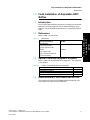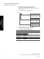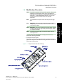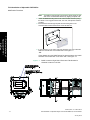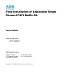
1
Field Installation of Adjustable Single
Channel PAPI Baffle Kit
Service Bulletin
Document Number
ALN152, 03 Sep 2011,
Rev. C , 1 March 2012
ADB Airfield Solutions
P.O. Box 30829
977 Gahanna Parkway
Columbus, OH 43230
Tel. (614) 861-1304
Fax. (614) 864-2069
Copyright © 2011 ADB Airfield Solutions. All rights reserved
1.0 Field Installation of Adjustable PAPI Baffles . . . . . . . . . . . . . . . . . . . . . . . . . . . . . . . . . . . . 1-1
1.1 Introduction . . . . . . . . . . . . . . . . . . . . . . . . . . . . . . . . . . . . . . . . . . . . . . . . . . . . . . . . . . . . . . . . . . . . . . . .
1.2 References. . . . . . . . . . . . . . . . . . . . . . . . . . . . . . . . . . . . . . . . . . . . . . . . . . . . . . . . . . . . . . . . . . . . . . . . .
1.3 Special Tools and Equipment Required. . . . . . . . . . . . . . . . . . . . . . . . . . . . . . . . . . . . . . . . . . . . . . . . . . .
1.4 Items Included in PAPI Baffle Retrofit Kits . . . . . . . . . . . . . . . . . . . . . . . . . . . . . . . . . . . . . . . . . . . . . . . . .
1.4.1 PAPI Baffle Retrofit Kit Ordering Code . . . . . . . . . . . . . . . . . . . . . . . . . . . . . . . . . . . . . . . . . . . . . . . .
1.5 Baffle Kit Parts List for 2/4-Box PAPI . . . . . . . . . . . . . . . . . . . . . . . . . . . . . . . . . . . . . . . . . . . . . . . . . . . . .
1.6 Modification Procedure . . . . . . . . . . . . . . . . . . . . . . . . . . . . . . . . . . . . . . . . . . . . . . . . . . . . . . . . . . . . . . .
1-1
1-1
1-1
1-1
1-2
1-2
1-3
Field Installation of Adjustable PAPI Baffles
Introduction
1.0 Field Installation of Adjustable PAPI
Baffles
1.1
Introduction
This service bulletin provides instructions for modifying the horizontal
light beam coverage of the PAPI unit for obstacle avoidance in the
approach area for the ADB Airfield Solutions’ 1-lamp Single Channel
PAPI.
1.2
References
Table 1.1.
1.3
1 - Field Installation of
Adjustable PAPI
Baffles
Refer to Table 1 for references.
References
Reference Description
ADB Airfield Solutions’s Part
Number
USER MANUAL:
Single-Channel PAPI,
Precision Approach Path
Indicator
Type L-880 & L-881,
Style A (Voltage-Powered) &
B(Current-Powered)
96A0379
Special Tools and Equipment Required
Refer to Table 2 for the special tools and equipment. This equipment
is not supplied.
Table 1.2.
Table 2. Required Equipment Not Supplied
Description
Walkie-talkies or other form of communication
Small Phillips screwdriver
Combination square or machinist’s square
Instruction manual for PAPI part number 96A0379
1.4
Quantity
2
1
1
1
Items Included in PAPI Baffle Retrofit Kits
This subsection provides the PAPI Baffle Retrofit Kit ordering code,
and a parts list for 2-box and 4-box baffle kits.
ALN152, Rev. C 1 March 2012
Field Installation of Adjustable Single Channel PAPI Baffle Kit, Service Bulletin
28 July 2010
1-1
Field Installation of Adjustable PAPI Baffles
Baffle Kit Parts List for 2/4-Box PAPI
1.4.1 PAPI Baffle Retrofit Kit Ordering Code
See Figure 1.1 to determine the part number for a particular PAPI
Baffle Retrofit Kit.
Figure 1.1.
PAPI Baffle Retrofit Kit Part Ordering Code
94A 0570 - X X X
Cutoff – Sec Obs
1 - Field Installation of
Adjustable PAPI
Baffles
0 = No Secondary Obs
1 = Cut-Off 0.0 to 3.3 Degrees
2 = Cut-Of f 3.1 to 6.4 Degrees
3 = Cut-Off 6.3 to 10.0 Degrees
Cutoff – Pr i Obs
1 = Cut-Off 0.0 to 3.3 Degrees
2 = Cut-Of f 3.1 to 6.4 Degrees
3 = Cut-Off 6.3 to 10.0 Degrees
L ight Box
2 = 2-Box PA PI System
4 = 4-Bo x PA PI System
1.5
Baffle Kit Parts List for 2/4-Box PAPI
Refer to Table 1.3 for the Baffle Kit parts list.
Table 1.3.
Baffle Kit 94A0570-XXX, Parts per Unit
Baffle Mounting Plate
Baffle (0.0 -3.3)
Baffle (3.1 – 6.4)
Baffle (6.3 – 10)
Pan head screws, 632 x 0.75 long
Lockwasher, Split #6
Hex Nut, 6-32
Pan head screws, 832 x 0.38 long
1-2
Part Number
60C1672
60B1673-1
60B1673-2
60B1673-3
One Obstruction Two Obstructions
1
1
1
2
64A0198-12
2
4
66A0026-11
65A0015-11
2
2
4
4
64A0966/06
2
4
ALN152, Rev. C 1 March 2012
Field Installation of Adjustable Single Channel PAPI Baffle Kit, Service Bulletin
28 July 2010
Field Installation of Adjustable PAPI Baffles
Modification Procedure
Modification Procedure
Note:
One baffle is required for EACH PAPI Light Box. Each set of
baffles are to be the same cut-off range. More than one
baffle type (cut-off range) can be ordered depending upon the
application. Contact ADB Airfield Solutions if you are not
sure about the cut-offs required for your particular
application.
Note:
The estimated time required is 60 minutes per PAPI Light
Box.
Note:
WARNING: Only personnel authorized to work on high
voltage equipment should make the modifications described
in this service bulletin.
Note:
WARNING: Disconnect equipment from line voltage. Failure
to observe this warning may result in personal injury, death,
or equipment damage.
Note:
Coordinate a power outage for the PAPI system with Air
Traffic personnel.
To modify the horizontal light beam coverage of the PAPI unit,
perform the following procedure:
1. De-energize the PAPI system.
Depending on the location of the obstruction in the approach area
(right or left side), attach the baffle mounting plate on the back side of
the enclosure filter bracket.
Figure 1.2.
Single Channel PAPI Box Assembly
ALN152, Rev. C 1 March 2012
Field Installation of Adjustable Single Channel PAPI Baffle Kit, Service Bulletin
28 July 2010
1-3
1 - Field Installation of
Adjustable PAPI
Baffles
1.6
Field Installation of Adjustable PAPI Baffles
Modification Procedure
Note:
The baffle mounting plate is mounted on either the left or right
side of the enclosure filter bracket by flipping the plate over.
2. Fasten the Baffle Mounting Plate to the enclosure filter bracket by using
the #6-32 x 0.75 long pan head screws, hex nuts, and split lock washers
provided.
3. Insert the #6 screws through the plate and the mating slots in the
enclosure filter bracket located at the end of the filter slot.
1 - Field Installation of
Adjustable PAPI
Baffles
4. IF the obstacle is on the LEFT side of the approach area, then install the
baffle over the filter slot on the RIGHT side. See Figure 1.3.
-ORIF the obstacle is on the RIGHT side of the approach area, then install
the baffle over the filter slot on the LEFT side. See Figure 1.4.
Figure 1.3.
1-4
Baffle Located on Right Side of Enclosure Filter Bracket for
Obstacle Located on Left Side
ALN152, Rev. C 1 March 2012
Field Installation of Adjustable Single Channel PAPI Baffle Kit, Service Bulletin
28 July 2010
Field Installation of Adjustable PAPI Baffles
Modification Procedure
Baffle Located on Left Side of Enclosure Filter Bracket for
Obstacle Located on the Right Side
1 - Field Installation of
Adjustable PAPI
Baffles
Figure 1.4.
Note:
Figure 1.5.
If both sides are obstructed, complete one side at a time.
PAPI Signal Viewing Zone
Obstacle Located in the RIGHT
SIDE of the Approach Area
See Fig 1.
10 Degree Zone either side of R/W
Centerline from where the PAPI
signal can be observed
Runway
Centerline
4 Mile Radius
Obstacle Clearance
Zone
PAPI Units 2 or 4 Boxes
Obstacle Located in theLEFT
SIDE of the Approach Area
See Fig 2.
ALN152, Rev. C 1 March 2012
Field Installation of Adjustable Single Channel PAPI Baffle Kit, Service Bulletin
28 July 2010
1-5
Field Installation of Adjustable PAPI Baffles
Modification Procedure
5. Take a combination square or machinists’ square of appropriate length,
and square the Baffle Mounting Plate with the top edge of the filter
Enclosure Filter Bracket. See Figure 1.6.
Figure 1.6.
Squaring Top Edge of Baffle Mounting Plate
Baffle Mounting Plate Screws
1 - Field Installation of
Adjustable PAPI
Baffles
6. Using the #10-32 x 0.38 large screws, and hex nuts supplied with the
baffle, install baffle as required for the application. Two #10-32 tapped
holes are located in the Baffle Mounting Plate.
Note:
Until the cutoff has been confirmed, the two screws should
only be finger tight.
7. Apply power to the lamp.
Note:
It may be necessary to lower the PAPI unit in elevation for the
individual to see the light beam. See manual 96A0379 for
any required alignment adjustment.
8. Position someone equipped with a walkie-talkie at the edge of the
obstacle or as far out from the edge the beam where cutoff is desired.
Move the baffle along the aperture of the baffle mounting plate until the
light beam cut-off is seen by the individual who is standing in front of the
obstacle. Use a combination square to make sure the machined edge on
the baffle is perpendicular to the top edge of the Baffle Mounting Plate.
Tighten the two screws on the baffle. See Figure 1.7.
1-6
ALN152, Rev. C 1 March 2012
Field Installation of Adjustable Single Channel PAPI Baffle Kit, Service Bulletin
28 July 2010
Field Installation of Adjustable PAPI Baffles
Modification Procedure
Figure 1.7.
Squaring Baffle Plate with Top Edge of Baffle Mounting Plate
9. Energize the lamp in the PAPI unit, and verify that the light beam cannot
be seen by the individual stationed at the obstacle. If the light beam is
visible, repeat Step 8.
10.Disconnect power from the PAPI unit, remove the jumper from tilt switch
(if installed), and reinstall the red filter. The red filter's ground edge must
be installed facing down. If the filter is dirty, use a soft cotton cloth
moistened with alcohol to clean the filter.
After the filter has been reinstalled, recheck the cutoff to make sure it
is correct for each PAPI Light Box. If the settings are correct, remove
ONE SCREW AT A TIME AND PLACE A DROP OF LOCTITE 242, or
equal, thread locking compound on the threads. Retighten the
screws. Repeat this process for each screw used to secure the baffle.
11.Repeat Steps 1 through 13 for the remaining PAPI units in the system.
The individual observing the horizontal cutoff for the PAPI units should
remain at the same position for all observations.
12.If the PAPI units were lowered in elevation, the units will require
realignment and the tilt switches will need to be leveled. Consult the
subsection Aligning Units in the Installation sections of instruction manual
96A0379 for instructions to align the PAPI and level the tilt switches.
Before putting the PAPI system into service, a flight check of the PAPI
system is required to determine if all horizontal cutoffs of the PAPI
beams are properly located relative to the obstacle(s).
13.After the cut-off angle has been verified, remove jumpers from the Tilt
Switch by reversing the procedure as outlined in Step 8. In addition, see
instruction manual 96A0379 to verify that the Tilt Switch is wired correctly
BEFORE PLACING PAPI IN SERVICE.
Note:
CAUTION: These adjustable baffles have been designed to
be used in ADB Airfield Solutions’ PAPI light boxes to alter
the horizontal cut-off angle avoidance of obstacles. The
customer is responsible for the proper installation and
verification that the horizontal cutoff produced by the
baffles meets the requirements set by the FAA for
obstacle avoidance. Therefore ADB Airfield Solutions
asserts that it be held harmless for the end use of the ADB
Airfield Solutions PAPI in this special baffle application.
ALN152, Rev. C 1 March 2012
Field Installation of Adjustable Single Channel PAPI Baffle Kit, Service Bulletin
28 July 2010
1-7
1 - Field Installation of
Adjustable PAPI
Baffles
Baffle Screws
Field Installation of Adjustable PAPI Baffles
Modification Procedure
1 - Field Installation of
Adjustable PAPI
Baffles
1-8
ALN152, Rev. C 1 March 2012
Field Installation of Adjustable Single Channel PAPI Baffle Kit, Service Bulletin
28 July 2010
ADB Airfield Solutions
Leuvensesteenweg 585
B-1930 Zaventem
Belgium
Tel: +32 (2) 722.17.11
Fax: +32 (2) 722.17.64
European Authorized Representative
ADB Airfield Solutions, LLC
977 Gahanna Parkway
Columbus, OH 43230
USA
Tel: +1 (614) 861-1304
+1 (800) 545-4157
Fax: +1 (614) 864-2069
[email protected]
ADB Airfield Solutions, Ltd.
5500 North Service Road, Suite 1108
Burlington, Ontario
L7L 6W6 Canada
Telephone: (905) 331-6887
Fax: (905) 331-9389
www.adb-airfieldsolutions.com
© 2010 ADB Airfield Solutions, LLC. All Rights Reserved.
ADB is a registered trademark of ADB Airfield Solutions, LLC. Product names mentioned may be trademarks of their
respective companies. Specifications are subject to change without notice.