1
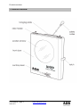
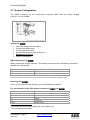
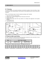
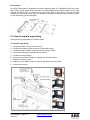
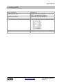
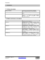
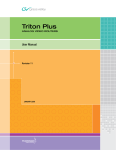
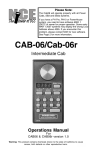
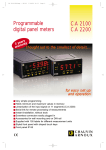
WARP Colour Changer - CC/W
User Manual
Issue 2.0
Lighting Technologies
M 6043
1106.06.043
Index
Index
INDEX ................................................................................................................................................... 1
1.
PRODUCT OVERVIEW ............................................................................................................... 2
2.
PRODUCT DESCRIPTION ......................................................................................................... 3
2.1.
CONSTRUCTION..................................................................................................................... 3
2.2.
MOTOR AND FAN ................................................................................................................... 3
2.3.
COLOUR FILTERS .................................................................................................................. 3
2.4.
SCROLLING MODES ............................................................................................................... 3
2.5.
COLOUR CHANGING SPEED .................................................................................................... 3
2.6.
RESET .................................................................................................................................. 3
2.7.
SYSTEM CONFIGURATION ...................................................................................................... 4
2.7.1. Adding the CC/WARP .......................................................................................................... 4
2.7.2. DMX mapping for the CC/WARP ......................................................................................... 4
2.7.3. Removing the CC/WARP ..................................................................................................... 4
2.7.4. Pin out definition of the 4 Pin output connector of WARP/M and CC/WARP .......................... 4
3.
OPERATION................................................................................................................................ 5
3.1.
LED INDICATORS .................................................................................................................. 5
3.2.
TEST BUTTON ...................................................................................................................... 5
3.3.
ROTARY ADDRESS SWITCH ..................................................................................................... 5
3.3.1. Fan speed ....................................................................................................................... 6
3.3.2. Continuous /step mode ................................................................................................... 6
3.3.3. Power on reset ................................................................................................................ 6
3.3.4. Fast / quit mode .............................................................................................................. 6
4.
SPECIAL OPERATION MODE ................................................................................................... 7
4.1.
REMOTE RESET ADDRESS ...................................................................................................... 7
4.1.1. Remote reset address - setup (999) ............................................................................... 7
4.2.
AUTO TRACE MODE (8XY) ...................................................................................................... 7
4.3.
GEL STRING MOVEMENT SPEED SETTING (9XX) ....................................................................... 7
4.4.
RESTORE TO FACTORY DEFAULT SETTING (600) ...................................................................... 7
4.5.
HOW TO GET THE BEST PERFORMANCE ................................................................................... 8
5.
MAINTENANCE .......................................................................................................................... 9
8.1.
8.2.
8.3.
CLEANING ............................................................................................................................. 9
HOW TO MAKE A GEL STRING .................................................................................................. 9
HOW TO REPLACE A GEL STRING........................................................................................... 10
6.
SPECIFCATIONS ...................................................................................................................... 11
7.
STANDARDS ........................................................................................................................ 12
7.1.
7.2.
8.
SAFETY STANDARDS ............................................................................................................ 12
RADIO INTERFERENCE STANDARDS ....................................................................................... 12
PERSONAL NOTES ............................................................................................................. 13
www.adblighting.com
User Manual - page 1
Issue 2.0
Product overview
1. Product overview
User Manual - page 2
Issue 2.0
www.adblighting.com
Product description
2. Product description
2.1 Construction
The housing of the WARP Colour Changer is made of sturdy aluminium plate to reduce weight. Outer
finish is a scratch resistant matt black epoxy powder coating.
2.2 Motor and Fan
The scrolling of the gel string is controlled by 2 DC Servo Motors which are mounted directly
to the plastic rollers. The motors are operated simultaneously to provide torque which enables
fast, smooth quiet and accurate positioning of the colour filter. Tension on the filter is also
maintained at the optimum level. DC fans provide excellent cooling for gel string extended life.
2.3 Colour Filters
Standard gel string, supplied, has a capacity of 16 frames (15 colours + clear).
2.4 Scrolling Modes
There are three scrolling modes available: Continuous, Step and Auto Trace.
•
•
•
Continuous Mode
The movement of the gel string is divided into 100 steps, and its position is proportional
to the intensity level of the signal on the control channel.
Step Mode
The movement of the gel string is divided into 16 steps, each step corresponds to a
separate colour. For approximately every 6.7% change of intensity level of the signal on
the control channel, the gel string will change one colour.
Auto Trace Mode
The unit continuously steps through each colour from the first to the last one, and then
back to the first colour on the string.
2.5 Colour changing speed
By employing DC servo motor control technique, fast colour changing speed is achieved.
Minimum time required to scroll from end to the end is 1.5s. In some applications, noise is of
more concern than speed. In this case scrolling speed can be reduced to minimize the noise
of mechanical movement. For example, the slowest speed is 20s, and is achieved by setting
the Gel string Movement setting to (9XX).
2.6 Reset
The colour changer automatically resets when power is applied. During reset, the gel string
rolls to the starting end first, then to the other end, then back to the starting end again to
enter the ready state.
The colour changer can also be reset from a control console. This feature makes life easier
when the colour changer is installed on a truss at the ceiling of the studio.
www.adblighting.com
User Manual - page 3
Issue 2.0
Product description
2.7 System Configuration
The XLR4 connector on the motor-house provides DMX data and Power Supply
(24V DC / 1A) for CC/WARP.
Adding the CC/WARP
•
•
•
•
•
•
Insert the changer into the WARP/M.
Connect the safety cable.
Connect the XLR4 cable1.
Set the DMX address of the changer to 1.
Rebalance the WARP/M2
Power up the WARP/M.
DMX mapping for the CC/WARP
WARP/M remaps the changer address. The changer becomes a part of the WARP/M personality.
CC/WARP has 3 parameters.
Channel 1
Channel 2
Channel 3
Colour (Position of String)
Fan Speed
Reset
In this case External 1 becomes colour, External 2 Fan Speed and External 3 enables a reset.
Removing the CC/WARP
After you have removed the changer, you must rebalance the WARP/M.
Pin out definition of the 4 Pin output connector of WARP/M and CC/WARP
PIN number
1
2
3
4
Case
1
2
Connector
COM
DMX DMX +
24 Vdc/1A
Shield ground
XLR4 cable with each CC/WARP ( ideal length to fit to WARP/M unit)
See user manual motorised WARP
User Manual - page 4
Issue 2.0
www.adblighting.com
Operation
3. Operation
For normal operation, set the DIP switches to the desired configuration and set the rotary
address switch to the desired DMX address. Set power and the unit is now ready to work.
3.1 LED Indicators
LED
Description
Red power LED
Red LED lights up when DC power is applied to
the unit.
Green LED lights up when the unit receives
proper DMX signal.
It flashes at short «ON», long «OFF» interval
when the gel string breaks.
It flashes at short «OFF», long «ON» interval
when the motor is jammed
Green signal LED
3.2 TEST Button
This switch button is used to test the unit. When used together with the DIP switches and
address switches, it sets the different operation modes available. After replacing the colour
filter (gel string) roller or adjusting a wrongly positioned gel string, press this button to RESET
the unit. The gel string will then scroll to the starting end, then to the other end, and finally
back to the starting end again, stopping at the control signal position.
3.3 Rotary address switch
For DMX operation, it is necessary to set the address of each colour changer to match the
dimmer number set on the control console. The address can be set between 1 to 512, by
means of the 3 rotary switches (X100, X10&X1).
www.adblighting.com
User Manual - page 5
Issue 2.0
Operation
FAN SPEED
Switch 1
Description
Off
On
LOW fan speed
HIGH fan speed
CONTINUOUS /STEP mode
Switch 2
Description
Off
STEP mode
The movement of the gel string is divided into 16
steps, and each step corresponds to a separate
colour. For approximately every 6.7% change of
intensity level of the signal on the control channel,
the gel string will change one colour
On
CONTINUOUS mode
The movement of the gel string is divided into 100
steps, and its position is proportional to the
intensity of the signal on the control channel
POWER ON RESET
Switch 3
Description
Off
Power on reset disable
The gel string scrolls to the starting end to enter
the ready state. If there is a control signal from
the console, it will go to the desired position.
On
Power on reset enable
The gel string scrolls to the starting end then to
the other end, then back to the starting end again.
If there is a control signal from the console, it will
go to the desired position.
FAST / QUIET mode
This mode will only operate if gel string movement speed setting is «900». This switch
optimizes the gel string scrolling speed with quietness of operation.
Switch 4
Description
Off
QUIET mode
The colour changer is set to scroll the gel string at
low speed, 2.5 s. Noise from moving gel string is
reduced to the minimum.
On
FAST mode
The colour changer is set to scroll the gel string at
high speed, 1.5 s. Noise from moving gel string
might be generated.
User Manual - page 6
Issue 2.0
www.adblighting.com
Special operation mode
4. Special operation mode
4.1 Remote reset address
If during normal operation the positioning of the gel string is incorrect, it is possible to bring it
back to the correct position by sending a RESET signal from a control console. This function
is especially useful if the unit is installed in a difficult to reach position. In order to be reset
from a console, the unit must receive a signal of FULL intensity level, maintained for a period
of more than 1 second at the Remote Reset Address.
Note: The factory-set default RESET address is 000. This effectively disables the Remote
RESET function because DMX does not support address 000).
Remote reset address - setup (999)
Set the address switches to «999», and press the «TEST» button to enter this mode. The
«signal» LED will then flash at 10 times per second. Set the desired RESET address and
press the «TEST» button again to confirm this address. The unit will then reset.
Remember to set the address switches back to the normal operation address, and
then switch the unit off and on again, or the unit will not operate properly.
Beware that WARP/M remaps the changers address. The changer becomes a part of the
WARP/M personality. External 3 become for example reset. (8 external parameters
available on WARP/M)
4.2 Auto trace mode (8XY)
The unit steps through each colour continuously from the first to the last colour and then
back to the first one. Set the address switches to 8XY and press the «TEST» button to enter
this mode. The value XY adjusts the speed of each stepping, the smaller the value, the faster
the stepping. «X» represents the speed of movement from starting end to the final end while
«Y» represents the speed of movement from the final end to starting end. When the value
XY is changed, it is necessary to press the «TEST» button or turn POWER OFF and then
ON to make the change effective.
4.3 Gel string movement speed setting (9XX)
16 different levels of speed of the gel string are available on CC/WARP changers. Set the
address to 9XX and press the «TEST» button to set the speed. The value XX (00-15) adjusts
the speed of the gel string movement, the smaller the value, the faster the speed.
For example the speed of the gel string ranges from 1.5s to 20s.
Remember to set the address switches back to the normal operation address, and
then switch the unit off and on again, or the unit will not operate properly.
4.4 Restore to factory default setting (600)
Set the address to 600 and press the TEST button to restore the factory default settings.
Factory default settings
Remote Reset Function
Gel string Movement Speed
Disable
Maximum
www.adblighting.com
User Manual - page 7
Issue 2.0
Special operation mode
Attention: A factory reset may become necessary in cases when the Colour
Changer does not function correctly. E.g. in case the ventilators are not
controllable and run constantly.
4.5 How to get the best performance
1.
2.
3.
4.
Maximum ambient temperature is 50° C.
This unit is suitable for indoor operation only
Always dim the light to the colour changer when not in use
Make sure you set the Normal Operation Address and Remote. RESET
Address before operation.
5. Make sure you restore the Normal Operation Address after setting
different modes of operation.
6. Remember to press the «TEST» button when changing a setting.
7. The unit stops automatically when the gel string breaks or when the
motor is jammed. In this case the «SIGNAL» LED blinks.
User Manual - page 8
Issue 2.0
www.adblighting.com
Maintenance
5. Maintenance
5.1 Cleaning
The colour changer uses optical encoding to calculate the position of the colour filter. If dust
accumulates on the optical devices, the accuracy in the positioning of the colour filter will be
degraded.
Refer to the following steps to clean the optical encoding units if needed:
1.
2.
3.
4.
Open the front door of the changer.
Slacken the 3 screws holding the cover of the motor on the left.
Remove the cover.
Remove dust in this area. Be very careful not to disrupt the alignment of the optical
sensors.
5. Re-install the cover.
6. Close the front door.
5.2 How to make a gel string
In order to make your own gel string, follow the chart here below for the correct size of each
filter. Note that the first and the last filter are different
Model
CC/W
Colour filter size (mm)
Filter No.1 & 16
Filter No.2 to 15
505 (W) x 197 (H)
315 (W) x 197 (H)
STANDARD GEL STRING FOR CCNVARP - 16 FRAMES, LEE REF. NR
1
2
3
4
5
6
7
8
9
10
11
12
13
14
15
16
LEE LEE LEE LEE LEE LEE LEE LEE LEE LEE LEE LEE LEE LEE LEE LEE
256 130 176 020 101 179 128 048 026 192 126 115 089 119 181 201
www.adblighting.com
User Manual - page 9
Issue 2.0
Maintenance
Use High Temperature Transparent Polyester adhesive tape (e.g. 3M #853) to join the colour
filters side by side. Make sure that there is a good adhesion by pressing firmly on the tape
against the filters. Join the first and the last colour filter to the rollers. You can use the
reference line marked on the roller for alignment. Please note that the tape should be taped
on the side facing you on the rollers.
5.3 How to replace a gel string
Each gel string is mounted on 2 plastic rollers.
To replace a gel string:
1. release the latch to open the front door.
2. slacken the locking screw at the top of the roller holder.
3. release the roller holders at the top of the 2 plastic rollers.
4. remove the existing gel string from the rollers.
5. install the new gel string.
6. press down the roller holders to engage the 2 plastic rollers.
7. fasten the locking screw.
8. slightly turn the plastic rollers to ensure that they can freely rotate
9. close the front door.
User Manual - page 10
Issue 2.0
www.adblighting.com
Specifications
6. Specifcations
Power consumption
Control input from CC/W
200 W max.
Output to CC/W colour changers
(CC/W - 4 Pin XLR male connector)
Operating environment
Operating environment temp
Size
Indoor use only (NOT Waterproof)
0° C - 50° C
Weight
Front aperture Ø
2.3 kg
Ø 185 mm
www.adblighting.com
User Manual - page 11
Issue 2.0
Standards
7. Standards
7.1 Safety standards
Conforms to council directive 73/23/EEC
(Low Voltage Directive) of CE marking 99
Luminaries Part 1: general requirements and
tests
Luminaries Part 2 : particular requirements
section 17: luminaries for stage lighting,
television, film and photographic studios
(outdoor and indoor)
Safety standards
EN60598-1
EN60598-2-17
7.2 Radio interference standards
Radio interference standards
EN55103-1
EN55103-2
EN61000-3-2
EN61000-3-3
User Manual - page 12
Issue 2.0
Conforms to council directive 89/336/EEC (EMC
directive) of CE marking 99
Electromagnetic compatibility product family
standard for audio, video, audio-visual and
entertainment lighting control apparatus for
professional use; Part 1: emission
Electromagnetic compatibility product family
standard for audio, video, audio-visual and
entertainment lighting control apparatus for
professional use; Part 2: immunity.
Electromagnetic compatibility (EMC); Part 3:
limits; Section 2 : limits for harmonic current
emissions (equipment input current 16 Ampere
per phase
Electromagnetic compatibility (EMC); Part 3:
limits; Section 3 : limitation of voltage
fluctuations and flicker in low-voltage supply for
equipment with rated current 16 Ampere
www.adblighting.com
8. Personal Notes
www.adblighting.com
User Manual - page 13
Issue 2.0
Subject to modifications
N.V. ADB-TTV Technologies S.A.
(Group Headquarters) Leuvensesteenweg 585, B-1930 Zaventem
Tel : +32.2.709.32.11, Fax : +32.2.709.32.80, E-Mail : [email protected]
France
ADB S.A.S.
Sales Office: 92, Avenue Jean Jaurès F-92120 Montrouge
Tel : +33.1.41.17.48.50, Fax : +33.1.42.53.54.76, E-Mail : [email protected]
Factory & Group Logistics Centre: Zone industrielle Rouvroy F-02100 Saint-Quentin
Tel : +33.3.23.06.35.70, Fax : +33.3.23.67.66.56, E-Mail : [email protected]
www.adblighting.com
Lighting Technologies
M-6043-E-06r
ADB - Your Partner for Light
Belgium