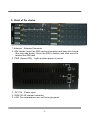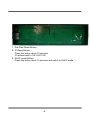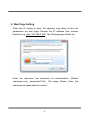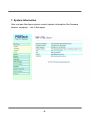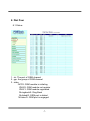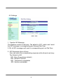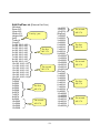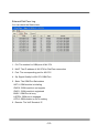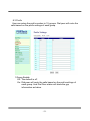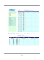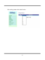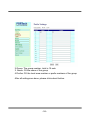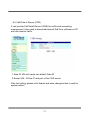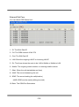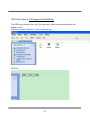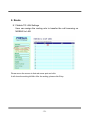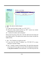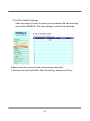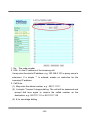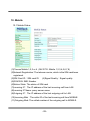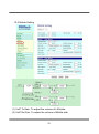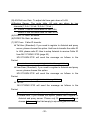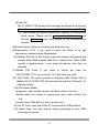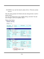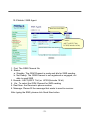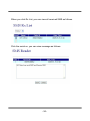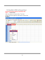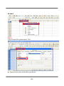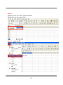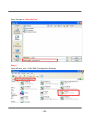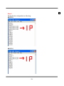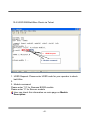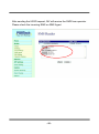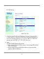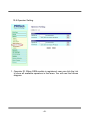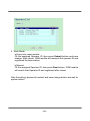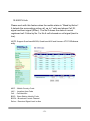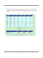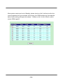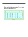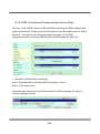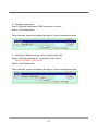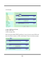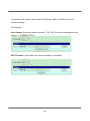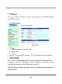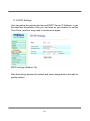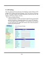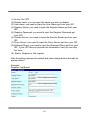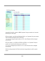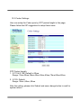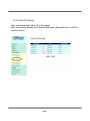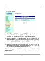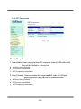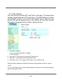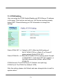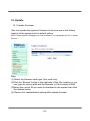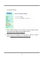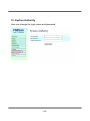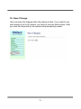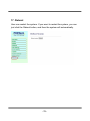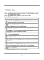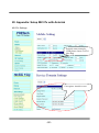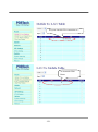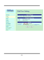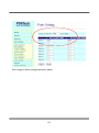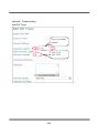
1
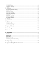
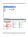
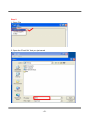
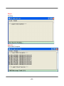
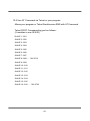
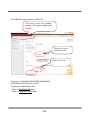
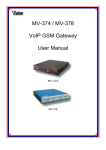
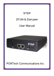
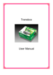
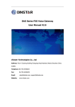
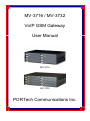
MV-3716 / MV-3732 VoIP GSM Gateway User Manual MV-3716 MV-3732 PORTech Communications Inc. 【Content】 1. Introduction........................................................................................................... 1 2. Function description ............................................................................................ 1 3. Parts list ................................................................................................................ 1 4. Dimension: 37*26*10 cm ...................................................................................... 2 5. Chart of the device ............................................................................................... 3 6. Web Page Setting ................................................................................................. 5 7. System Information .............................................................................................. 6 8. Dial Peer ................................................................................................................ 7 8.1 Status.............................................................................................................................. 7 8.2 Settings........................................................................................................................... 9 8.3 Prefix ............................................................................................................................. 13 8.4 Call Data to Server (CDR) ......................................................................................... 17 9. Route ................................................................................................................... 21 9.1 Mobile TO LAN Settings ............................................................................................ 21 9.2 Mobile to LAN Speed Dial Settings.......................................................................... 24 9.3 LAN to Mobile Settings............................................................................................... 25 10. Mobile ................................................................................................................ 28 10.1 Mobile Status............................................................................................................. 28 10.2 Mobile Setting............................................................................................................ 29 10.3 Mobile / SMS Agent:................................................................................................. 33 10.4 Send Bulk of SMS via Microsoft Excel .................................................................. 35 10.5 Use AT Command via Telnet or your program .................................................... 43 10.6 USSD SIM BaLANce Check via Telnet................................................................. 45 10.7 SIM Setting ................................................................................................................ 47 10.8 Operator Setting........................................................................................................ 49 10.9 BCCH Info.................................................................................................................. 51 10.10 USSD (Unstructured Supplementary Service Data) ......................................... 56 11. Network ............................................................................................................. 60 11.1 WAN Setting .............................................................................................................. 60 11.2 SNTP Settings........................................................................................................... 61 12. SIP Setting......................................................................................................... 62 12.1 Service Domain Setting ........................................................................................... 62 12.2 Ports Setting .............................................................................................................. 64 12.3 Codec Settings:......................................................................................................... 65 12.4 Codec ID Setting....................................................................................................... 66 12.5 DTMF Setting ............................................................................................................ 67 12.6 SIP Responses ......................................................................................................... 68 12.7 Other Settings ........................................................................................................... 70 13. STUN Setting..................................................................................................... 71 14. Update ............................................................................................................... 72 14.1 Update Firmware ...................................................................................................... 72 14.2 Default Settings......................................................................................................... 73 15. System Authority .............................................................................................. 74 16. Save Change ..................................................................................................... 75 17. Reboot ............................................................................................................... 76 18. Specification ..................................................................................................... 77 18.1 Protocols .................................................................................................................... 77 18.2 TCP/IP ........................................................................................................................ 77 18.3 Codec ......................................................................................................................... 77 18.4 Voice Quality ............................................................................................................. 77 18.5 GSM (MV-3716/MV-3732)....................................................................................... 78 19. Simple Steps ..................................................................................................... 79 20. Appendix: Setup MV-37x with Asterisk .......................................................... 80 1. Introduction MV-3716/MV-3732 is a 16 / 32 channels VoIP GSM Gateway for call termination (VoIP to GSM) and origination (GSM to VoIP). It is SIP based and compatible with Asterisk. It can enable to make 16 / 32 calls simultaneously from IP phones to GSM networks and GSM network to IP phone. 2. Function description 2.1 VoIP(SIP)、GSM conversion. 2.2 50 sets of LAN->MOBILE routes setting,50 sets of MOBILE->LAN routes setting. 2.3 Voice response for setting and status (dial in from mobile). 2.4 Series connections to save bills. 2.5 Standard SIP(RFC2543,RFC3261) protocol, *It communicates with other gateway or PC. 3. Parts list 3.1 「MV-3716/MV-3732」main body 3.2 Power adaptor Output 12V/9A, Input 100~240V Auto switching 3.3 Network cable 3.4 Antenna: MV-3716: 4 pcs / MV-3732: 8 pcs 3.5 Rack-mount accessories (compatible with 19“Rack) 3.6 User Manual -1- (3.1) MV-3732 (3.1) MV-3716 (3.2) Power adapter (3.4) (3.3) (3.5) 4. Dimension: 37*26*10 cm -2- 5. Chart of the device 1 Antenna:Antenna Connector 2. SIM Holder: Insert the SIM card as instruction and hear click sound (the chip side down); Press the SIM to bottom with click sound to remove the SIM card 3. PWR (Power LED):Light up when power is normal. 1. DC 12V:Power input. 2. WAN: RJ-45 internet connector 3. LAN: For maintenance use, not for any propose -3- 1. Dial Peer Reset Button 2. IP Reset Button: Press this button about 10 seconds IP restore back to 192.168.0.100 3. DHCP mode Button: Press this button about 10 seconds and switch to DHCP mode -4- 6. Web Page Setting When the IP setting is done, the operator may setup all the rest parameters via web page. Browse the IP address from Internet Explorer (e.g. http://192.168.0.100). The following page shows up: Enter the username and password for authentication. (Default username=voip, password=1234). The page follows when the username and password are correct. -5- 7. System Information User can see the demo system current system information like firmware version, company… etc in this page. -6- 8. Dial Peer 8.1 Status 1. ch: The port of GSM channel 2. grp: the group of GSM channel 3. state: INIT/0: GSM module is initialing IDLE/0: GSM module not register IDLE/1: GSM module registered M.ringback/0: Ring Back M.dialed/0: GSM port is dialed M.listen/0: GSM port is engaged -7- 4. 5. 6. 7. MNC: Mobile Network Code SQ: Signal quality Mobile: The caller number of the incoming/outgoing call to Mobile dir: The Arrow shows the route to be LAN to Mobile or Mobile to LAN a. < : LAN to Mobile b. > : Mobile to LAN 8. LAN: the IP address of the last incoming/outgoing call from/to LAN -8- 8.2 Settings 1. Transfer SIP Message The Replace contact to dial peer: The default is OFF, which won’t send the SIP message to corresponding port through Dial Peer. If ON, all SIP messages will send to corresponding port via Dial Peer. 2. SIP Response when all busy User can select the corresponding response while all ports are busy. The Default is 600 600 : Busy Everywhere (default) 408 : Request Timeout 480 : Temporarily unavailable 503: Service unavailable -9- 3. Dial Peer Working Mode a. OFF: To disable Dial Peer, user need to assign the port of GSM channel for the incoming calls from LAN side (E.g. Default ch1 is 5064 port; ch2 should be 5066 port and so on) b. Internal: to motivate Dial Peer, all incoming calls from LAN will come to dial peer port. Dial peer will route calls to idle channels(Default: 5060 port) c. External: All GSM Channel are controlled by external Dial peer program. External URL External Dial peer program’s IP address and port number -10- Edit DialPeer.ini (External Dial Peer) [Window] Xpos=512 Ypos=252 Width=471 Total ip / port Height=399 [Info] Total=16 [VoipIP] 1=192.168.0.100 2=192.168.0.100 3=192.168.0.100 The first 4=192.168.0.100 MV-378 5=192.168.0.100 6=192.168.0.100 7=192.168.0.100 8=192.168.0.100 9=192.168.0.110 10=192.168.0.110 11=192.168.0.110 The second 12=192.168.0.110 MV-378 13=192.168.0.110 14=192.168.0.110 15=192.168.0.110 16=192.168.0.110 [SipPort] 1=5060 2=5062 3=5064 The first 4=5066 MV-378 5=5068 6=5070 7=5072 8=5074 9=5060 The second 10=5062 11=5064 MV-378 12=5066 13=5068 -11- 14=5070 15=5072 16=5074 [RtpPort] 1=60000 2=60002 3=60004 4=60006 5=60008 6=60010 7=60012 8=60014 9=60000 10=60002 11=60004 12=60006 13=60008 14=60010 15=60012 16=60014 [PtcPort] 1=40000 2=40000 3=40008 4=40008 5=40016 6=40016 7=40024 8=40024 9=40000 10=40000 11=40008 12=40008 13=40016 14=40016 15=40024 16=40024 The second MV-378 The first MV-378 The second MV-378 The first MV-378 The second MV-378 External Dial Peer Log You can check the Statue here 1. CH: The number for GSM port of MV-37X 2. MvIP: The IP address of MV-37X for Dial Peer connection 3. Port: The corresponding port for MV-37X 4. Sq: Signal Quality for MV-37X GSM Port: 5. State: The GSM Port Sate status INIT/1: GSM module is initialing IDLE/0: GSM module is not register IDLE/1: GSM module is registered BUSY: GSM Port is busy LISTEN: GSM port is engaged OFF/0: GSM module is out of working 6. Remote: The VoIP Sender’s IP -12- 8.3 Prefix User can setup the prefix number in 15 groups. Dial peer will route the calls based on the prefix settings of each group 1.Group Enable Off: The default is off. On: Dial peer will route the calls based on the prefix settings of each group. And Dial Peer status will show the grp information as below. -13- Please click to select the group number of each channel -14- After setting, please click submit button -15- 2.Group: The group number, total is 15 sets 3. Name: Fill the name of the group 4.Prefixs: Fill the local area number or prefix numbers of the group After all settings are done, please click submit button. -16- 8.4 Call Data to Server (CDR) It can provide Call Detail Record (CDR) for traffic and accounting management. User need to download external Dial Peer software on PC and can monitor traffic. 1.Data ID: MV will create one default Data ID 2.Server URL: Fill the IP and port of the CDR server After the setting, please click Submit and save change button to wait for system reboot -17- External Dial Peer You can check CDR Statue here 1. ID: The MV’s Data ID 2. CH: The GSM channel of MV-37X 3. Cimi: The SIM Card ID 4. LAN: Show the outgoing LAN IP or Incoming LAN IP 5. Dir: The Arrow shows the route to be LAN to Mobile or Mobile to LAN 6. Mobile: The outgoing mobile number or incoming mobile number 7. tStart: When the call started(date and time) 8. tANS: The second answering the call 9. tEND: The second ending the call(duration) (tANS, tEND are the exactly talking seconds) 10. State: The GSM Port Sate status -18- CDR Files store at C:\Program Files\DialPeer The CDR log is stored in this “cdr” file each hour, which includes all gsm port call detials record. If there’s no calls in this hour, it won’t creat any log. CDR File -19- Example: 1. Id=Mv-000000: The MV’s Data ID 2. Ch=1: The 1st channel for MV ID 3. Cimi=466922202956645 : The SIM card ID for this GSM port 4. dir=L2M: The route is LAN to Mobile (If it’s Mobile to LAN, that shows M2L) 5. iurl=192.168.0.96: The incoming IP 6. omb=0980763178: The outgoing number 7. tStart=4e7a0682(2011/09/21 15:45:06): The duration for the call 8. tEnd=+26: The call end on 26th second 9. state=LANEnd: The call hang up on LAN side. -20- 9. Route 9.1 Mobile TO LAN Settings User can assign the routing rule to transfer the call incoming on MOBILE to LAN Please move the mouse to that red arrow spot and click It will show the setting bLANk. After the setting, please click Entry. -21- 1. MCH: the code of mobile channel 2. CID: (1) It may enter the whole number, e.g. 0911111111 (2) Only part of the number (prefix) e.g. 0911* means any number starting with 0911 will be accepted (3) * means all numbers can be accepted Please note the priority of the rules. The item which has more digits will have higher priority. If the digits are the same, then former one gets the higher priority. 3. URL:The IP address to transfer this call (1) It may enter the whole IP address, e.g. 192.168.0.101 or proxy extension or phone number. (2) If an ‘*’ entered, it means 2-stages-dialing. The call will be answered and prompt dial tone again to receive the IP address/sip extension or any phone number as the destination. The caller may enter the -22- IP such as 192*168*0*101#. *If the device have register proxy server/Asterisk ,you can enter any destination phone number. Please note the proxy server/Asterisk need to set the route of destination phone number. 4. SEL: Select the one to delete -23- 9.2 Mobile to LAN Speed Dial Settings NOTE: It’s for 2 stage dialing mode The call will be answered and prompt dial tone again. When the caller may enter the “Num”, system will connect the “URL” as destination. E.g. item: 0 Name: JACK URL: 192.168.0.156, When the caller hear dial tone and enter 0, system will connect 192.168.0.156 -24- 9.3 LAN to Mobile Settings User can assign 24 sets of routing rule to transfer the call incoming from LAN to MOBILE. The chart setting is used for all channels. Please move the mouse to that red arrow spot and click It will show the setting bLANk. After the setting, please click Entry. -25- 1. No. : The code number 2. URL: It’s the IP address of the incoming call It may enter the whole IP address, e.g. 192.168.0.101 or proxy server’s extension. If a simple ‘*’ is entered, means no restriction for the incoming IP address. 3. Call Num: (1). May enter the whole number, e.g. 0911111111 (2). A simple *”means 2-stages-dialing. The call will be answered and prompt dial tone again to receive the called number as the destination, e.g. 0911111111 or 0911111111# (3). # for one-stage dialing -26- (4). # ['d'n]['a'ppp] for one-stage-dialing [...] is option 'd'n means to delete the beginning n codes, 'a'ppp means to add 'ppp' in front. For example #d123a456 means one-stage dialing, delete the first 123 from your destination number, then add 456 in front as the new destination number. Example: LAN to Mobile: *, # (1)MV-3716/MV-3732 and LAN Phone both need to register proxy server or Asterisk. (2)Proxy server/asterisk set the route that the prefix of destination number (3)When you dial any destination phone number from LAN phone, MV-3716/MV-3732 will connect this call auto. 4.SEL : Select the one to delete -27- 10. Mobile 10.1 Mobile Status (1)Choose Mobile 1,2,3 or 4 (MV-3732: Mobile 1,2,3,4,5,6,7,8) (2)Network Registration:The telecom carrier, which is the SIM card been registered. (3)SIM Card ID:SIM card ID. (4)Signal Quality:Signal quality. (5)GSM S/N: IMEI Number (6)Motion State: The status of SIM card (7)Incoming IP:The IP address of the last incoming call from LAN. (8)Incoming IP Name: proxy server name (9)Outgoing IP:The IP address of the last outgoing call to LAN. (10)Incoming Mob:The caller ID of the last incoming call from MOBILE. (11)Outgoing Mob: The called number of the outgoing call to MOBILE. -28- 10.2 Mobile Setting (1) VoIP Tx Gain: To adjust the volume of LAN side. (2) VoIP Rx Gain: To adjust the volume of Mobile side. -29- (3)LAN Dial tone Gain: To adjust dial tone gain down of LAN. (4)Routing Range: The route table -50 sets can share by two channels(1,2 ch / 3,4 ch / 5,6 ch / 7,8 ch ) ex: Mobile 1 use the route table for item 0-24, Mobile 2 use the route table for item 25-49 (5)CODEC Tx Gain: as above (6)CODEC Rx Gain: as above (7) SIP From: Caller ID transfer Tel/User (Standard): If you need to register to Asterisk and proxy server, please choose this option. And how to transfer the caller ID to LAN, please refer 21.How to setup Asterisk to receive Caller ID from MV-3716/MV-3732 (page 42) MV-3716/MV-3732 will send the message as follows in the Packet. From: “caller number” <sip:[email protected]>;tag=51088abb User/User (Standard): If you need to register to Asterisk and proxy server, please choose this option. MV-3716/MV-3732 will send the message as follows in the Packet. From: " 3001" <sip:[email protected]>;tag=51088abb Tel/Tel : MV-3716/MV-3732 will send the message as follows in the Packet. From: "caller number" <sip: caller number @192.168.0.228>;tag=6ac93f7c ※Please note: If you choose this option, please don’t register to Asterisk and proxy server. Please only fill proxy server IP and choose Active: on (else field empty) in sip setting/service domain -30- User/Tel MV-3716/MV-3732 will send the message as follows in the Packet. From: “Username” <sip: caller number @192.168.0.228>;tag=7f130947 ※ If you choose this option, please don’t register to Asterisk and proxy server. Please only fill proxy server ip,Username and choose Active: on (else field empty) in sip setting/service domain (8)Answer Delay: Delay for incoming call when the ring. (9)Presentation CLID: If you need to block the Caller Id for call termination, please choose Suppression (10) Restart Dial Fail: In this feature, user can initialize and register the module while GSM module dials fail in couple times. When GSM module is dysfunctional, it can avoid the device shut down in advance. (11)Mobile PIN Code: If you need to unlock pin code via MV-3716/MV-3732, you can click “On” and enter pin code. (12) Dial Prefix: The prefix number of outgoing calls. When LAN to Mobile, MV-3716/MV-3732 will automatically add the “Dial prefix” for outgoing mobile. (13)LAN Answer Mode: Answered: when mobile answer, and then connect the call Alerted: when the mobile is ringing back tone, then connect the call Income: when LAN dial out, then connect soon (14) Init AT Cmd: User can fill the AT Command for GSM module (15) Band Type: You can manual setting according to your GSM Frequency of carrier. -31- (16) ON/Off: If you use this channel, please click on. Otherwise, please click off. After the setting, please click Submit and save change button to wait for system reboot You can click Submit All to copy to Mobile setting, and select Yes and save change to wait for the system reboot Please check below: -32- 10.3 Mobile / SMS Agent: Read received SMS 2 mode: ASC7(ASCII 7 bit) UCS2(Unicode 16 bit) 1. Port: The GSM Channel No. 2. Status: a. Standby: The GSM Channel is ready and idle for SMS sending b. Not Ready: The GSM Channel is not registered or engaged, not able to send SMS 3. Encode : ASC7(ASCII 7 bit) or UCS2(Unicode 16 bit) 4. Via : To select the GSM Channel for SMS sending 5. Dest Num: the Receiver’s phone number 6. Message: Please fill the message that wants to send to receiver. After typing the SMS, please click Send Now button -33- When you click Rx List, you can view all received SMS as follows. Click the serial no, you can view message as follows. -34- 10.4 Send Bulk of SMS via Microsoft Excel First of all, please open a new Excel file. Step 1 Format Cells Here, we need you to format cells to “Text” first. Please click mouse right key, and choose “Format Cells” BLANk A -35- BLANk B Step 2 In the Format Cells, please select “Text” Please do this action for BLANk A and B both. -36- Step 3 BLANk A: is for you to key “phone numbers” BLANk B: is for you to key “text” Step 4 save the file -37- Save the type as “Unicode Text” Step 5 Open MVsms_exe - MV-SMS (Configuration Settings) -38- Step 6 Please do the configuration as following: MV-3732 MV-3716 =2 -39- MV-372 & MV-370 =1 Step 7 Run MV-SMS program -40- Step 8 1. Open File 2. Open the “Excel file” that you just saved -41- Step 9 Sending Step 10 Send SMS Complete -42- 10.5 Use AT Command via Telnet or your program Allows your program or Telnet Send/receive SMS with AT Command Telnet PORT Corresponding port as follows: (2 modules in one SLAVE) SLAVE 1:1301 SLAVE 2:1302 SLAVE 3:1303 SLAVE 4:1304 SLAVE 5:1305 SLAVE 6:1306 SLAVE 7:1307 SLAVE 8:1308….. *MV-3716 SLAVE 9:1309 SLAVE 10:1310 SLAVE 11:1311 SLAVE 12:1312 SLAVE 13:1313 SLAVE 14:1314 SLAVE 15:1315 SLAVE 16:1316….. *MV-3732 -43- Please enter account and password Choose module Enter “ate1”,then you can see your at command below Enter at+cmgs=”phone number” Enter short message and ctrl+Z -44- 10.6 USSD SIM BaLANce Check via Telnet 1. USSD Request 2. Module command 1. USSD Request: Please enter USSD code for your operator to check baLANce 2. 3. Module command: Please enter “15” for Siemens BG2W module Please enter “0” for Simcom module User can check this information on main page on Module Description -45- After sending the USSD request, MV will receive the SMS from operator Please check the incoming SMS on SMS Agent -46- 10.7 SIM Setting 1. CU ID: It’s the ID for MV and SIM Server Transfer Protocol, within 1~9999. Each MV under same SIM Sever should setup different CU ID, and no reusing parameter. E.g. If you put “888” on 1st MV-3732 that you can’t use “888” on 2nd MV-3732, and so on. 2. Mode a. Local: Disable Remote SIM feature b. Bank: Enable Remote SIM Bank feature, and manage SIM card on SBK-32 SIM Bank. c. Server: Enable Remote SIM Server feature, and allocate SIM cards on SBK-32 SIM Bank. -47- 3. Mobile a. ID: Put in 8 digits (hexadecimal, also base 16), which used for GSM Module ID identification to Remote SIM protocol. User can define the ID. IF it’s Server Mode, just leave it default. If it’s Bank Mode, No reusing GSM Module ID for same SIM Bank. b. Group: Fill in SIM Group number for Remote GSM module. Server follow SIM Group Number to allocate SIM card to correspond GSM module 4. Card ID: Put in 8 digits (hexadecimal, also base 16), which used for SIM Card ID identification to Remote SIM protocol. User can define the ID. If it’s in Server Mode, Card ID can be bLANk or default. As for Bank Mode, Card ID must be corresponding to SIM Card ID of SIM Bank. 5. Bank URL: If it’s Bank Mode, please fill SIM Bank IP and Port Number. On other hand, please leave bLANk for Server Mode. 6. Server URL: If it’s Server Mode, please fill SIM Server IP and Port Number. On other hand, please leave bLANk for Bank Mode. 7. Status: User can check the SIM Card ID of GSM module and IP, Port Number of SIM bank. After the setting, please click submit and save change button and wait for system reboot -48- 10.8 Operator Setting 1. Operator ID: When GSM module is registered, user can click the List to show all available operators in that area. You will see like follows diagram. -49- 2. Work Mode: a.Every time reset module: Fill the assigned Operator ID, then press Submit bottom and save change. After reboot, GSM module will research the operator ID and registered the base station. b.Manual: Fill the assigned Operator ID, then press Now bottom. GSM module will search that Operator ID and registered after reboot. After the setting, please click submit and save change button and wait for system reboot -50- 10.9 BCCH Info Please work with this feature when the mobile status is “Stand by/Active”. It detects the surrounding active cell, up to 7 cells and shows Cell ID, signal and best signal (RXlev). The No.0 shows the data of current registered cell. Follow by No.1 to No.6 cell is based on cell signal (best to low). NOTE: Support Quad band-BG2W, Quad band-M10 and firmware V10.185 above only. MCC : Mobile Country Code LAC : Location Area Code Cell : Cell Identifier BSIC: Base Station Identity Code BCCH: Broadcast Control Channel RxLev: Received Signal level in dbm -51- How to Configure 1. You can choose a BCCH channel by clicking on the cell. The module will automatically register in the new BCCH. E.g. If you would like to register BCCH channel on No.4 cell, please click no4 select like below. -52- 2. System will show the cell number information once you select on Preferred this Cell form. Please click the submit button and Save Change, and wait for system reboot -53- After system restart and turn to Standby, please check on No.0 cell and confirm the current registered cell you selected. At the point, the GSM module won’t provide the data of surrounding cell signal, but shows -110dbm on No.1 to No.6 RxLev, which means GSM signal 0. -54- 3. If you would like to research all the surrounding BCCH cells again, please cancel Preferred this Cell selection first and send Submit, Save Change to restart the gateway. That, System can detect the surrounding active cell, up to 6 cells and display Cell ID, signal and best signal (RXlev). -55- 10.10 USSD (Unstructured Supplementary Service Data) User can check USSD screen for SIM baLANce remaining and SIM recharge (add value) automatically. Please work with this feature when the mobile status is “Stand by/Active”. And ensure your Service provider has given you a USSD string(Command) for checking SIM BaLANce and Recharge the SIM Card. 1. BaLANce (SIM baLANce remaining) Step1: Enter BaLANce checking USSD command in column Step 2: Click Send button When selected, system will check the baLANce of SIM and display the reply of receive message as below -56- 2. Recharge (add value) Step1: Enter the Recharging USSD command in column Step 2: Click Send button When selected, system will display the reply of receive message as below 3. Checking (If above ways are failed, please select this) Step 1: Enter the complete AT command in Cm3 column Ex. AT+CUSD=1,*145*11#,15 Step 2: Click Send button When selected, system will display the reply of receive message as below -57- 4. Rx Decoder a. None: GSM Format (Default) b. ASC7: ASCII 7bit c.UCS2: Unicode 16bit When user select default GSM Format(None), it may not receive correct GSM code due to the different operator or GSM module/chipset. Please check below example, -58- In this case, user need to select other RX Decoder (ASCII or UCS2) to receive correct message. For Example, None format: When user send command, “*145*11#”, the return message show on system, “C1F1B80CA797C9” ASC7 Format: In this format, the return message is “Accepted” -59- 11. Network User can check the Network status and configure the WLAN Settings and SNTP settings. 11.1 WAN Setting 1. IP Type a. Fixed IP (Default IP: 192.168.0.100) b. DHCP Client c. PPPoE 2. Main IP: The current IP address. The IP chaning need to under the Fixed IP mode. 3. PPPoE Setting The PPPoE Configuration item is to setup the PPPoE Username and Password. If you have PPPoE account from the Service Provider, please input the Username and the Password correctly After the setting, please click submit and save change button and wait for system reboot -60- 11.2 SNTP Settings User can setup the primary and second SNTP Server IP Address, to get the date/time information. Also you can base on your location to set the Time Zone, and how long need to synchronize again. SNTP settings (Default: On) After the setting, please click submit and save change button and wait for system reboot -61- 12. SIP Setting User can setup the Service Domain, Port Settings, Codec Settings, RTP setting, RPort Setting and Other Settings. If the VoIP service is provided by ISP, you need to setup the related information correctly then you can register to SIP Proxy Server correctly. 12.1 Service Domain Setting In Service Domain Function you need to input the account and the related information in this page please refer to your ISP Provider. You can register three SIP accounts. You can dial the VoIP phone to your friends via first enable SIP account and receive the phone from the tree SIP account. -62- (1) Active: On /OFF (2) Display name: you can input the name you want to display. (3) User name: you need to input the User Name get from your ISP. (4) Register Name: you need to input the Register Name get from your ISP. (5) Register Password: you need to input the Register Password get from ISP. (6) Domain Server: you need to input the Domain Server get from your ISP. (7) Proxy Server: you need to input the Proxy Server get from your ISP. (8) Outbound Proxy: you need to input the Outbound Proxy get from your ISP. If your ISP does not provide the information, then you can skip this item. (9) Status: Register or Not register After the setting, please click submit and save change button and wait for system reboot Example: Register VoipBuster Your Voipbuster username Your Voipbuster password Proxy Server’s IP -63- 12.2 Ports Setting Internal Dial Peer Port: default = 5060 (*important* this port number can’t coincide with SIP port or RTP port) SIP port: default = ch1:5064 ch2:5066 ch3:5068…etc (*important* this port number can’t coincide with dial peer port or RTP port) You can only change the port number on Ch1; other Channels will be changed automatically RTP port: default = ch1:20004 ch2:20006 ch3:20008…etc (*important* this port number can’t coincide with dial peer port or SIP port) You can only change the port number on Ch1; other Channels will be changed automatically After the setting, please click Submit and save change button to wait for system reboot -64- 12.3 Codec Settings: User can setup the Codec priority, RTP packet length in this page. Please follow the ISP suggestion to setup these items. RTP Packet Length 1. G.711& G.729: Default is 20ms. Range: 10ms,20ms,30ms,40ms,50ms,60ms,70ms,80ms,90ms 2. G.723: Default: Range: 30ms ,60ms, 90ms After the setting, please click Submit and save change button to wait for system reboot -65- 12.4 Codec ID Setting User can setup the Codec ID in this page. After the setting, please click Submit and save change button to wait for system reboot -66- 12.5 DTMF Setting 1. Format: a. 2833: Default RFC2833, the type of DTMF Data Transfer Format b. Inband: The Type of Inband DMTF Data Transfer Format c. SIP Info: The Type of SIP-Info DMTF Data Transfer Format; 2. Duration: Default is -1. It’s the duration for MV-3716/MV-3732 to defect sender’s DTMF. If the parameter is 0, MV-3716/MV-3732 won’t detect sender’s DTMF. Parameter is 0~999 seconds. After that duration, MV-3716/MV-3732 won’t detect DTMF. 3. Debounce: Default is 80ms.User can adjust for own. If DTMF is adding more digits, please increase parameter over 80. If DMTF is lost digit, please decrease parameter less than 80. After the setting, please click Submit and save change button to wait for system reboot -67- 12.6 SIP Responses Mobile Busy Response 1. Unavailable: User can setup the SIP response code of LAN side while the call dial failed or in busy line a. 486 Busy Here (Default) b. 503 Service unavailable c. 480 Temporarily unavailable 2. Ring Timeout: User can setup the response SIP code of LAN side while operators hang up the no answered calls a. 486 Busy Here (Default) b. 503 Service unavailable c. 480 Temporarily unavailable -68- SIP Ring Response 1. 180 Ring on/off: LAN TO MOBILE two stage dialing can be turn off, therefore there will be no the Ring Back Tone, all the phone call will be transferred to prompt voice directly. (For this function, 183 must be turn on) 2. 183(Session Progress) [It means "on progressing"]: When you turn 183 on, it means you can hear the prompt voice while GSM side is busy we recommend you to turn this on if you use SIP Proxy. After the setting, please click Submit and save change button to wait for system reboot -69- 12.7 Other Settings User can setup the Hold by RFC and QoS in this page. To change these settings, please follow your ISP information. The QoS setting is to set the voice packets’ priority. If you set the value higher than 0, then the voice packets will get the higher priority to the Internet. But the QoS function still need to cooperate with the others Internet devices. 1. Hold RFC of Mobile: a. On: To activate Hold RFC of Moible b. OFF (Default) 2. Voice QoS : The setting of Voice QoS, Default is 40 3. SIP QoS : The setting of SIP QoS, Default is 40 4. SIP Expire Time : The setting of SIP Expire Time, Default is 40 After the setting, please click Submit and save change button to wait for system reboot You can click Submit All to copy to Mobile setting, and select Yes and save change to wait for the system reboot -70- 13. STUN Setting User can setup the STUN Enable/Disable and STUN Server IP address in this page. This function can help your VoIP device working properly behind NAT. Please following your ISP information to change the settings Public STUN OFF Default is OFF; While the WAN setting of MV-3716/MV-3732 is in Static IP or Private IP please selects Public STUN OFF. Public STUN ON While MV-3716/MV-3732 is working under Firewall or behind NAT, It will cause SIP can’t register, or one side communicate, please select Public STUN ON. STUN Server The STUN Server IP (Default: stun.iptel.org) STUN Port The STUN Port (Default: 3478) After the setting, please click Submit and save change button to wait for system reboot -71- 14. Update 14.1 Update Firmware User can update the system’s firmware to the new one or the factory reset to let the system back to default setting. NOTE: Please open the webpage from Internet Explorer, not compatible with FF or Google Chrome Step: (1) Select the firmware code type, Risc code only. (2)Click the “Browse” button in the right side of the File Location or you can type the correct path and the filename in File Location bLANk. (3)Select the correct file you want to download to the system then click the Update button. (4) Please click update/default setting after update firmware -72- 14.2 Default Settings 1. Restore default settings: User can restore the factory default settings to the system. All setting will restore default setting. The device IP still is the user original IP. 2. Restore factory all settings: All setting will be restored to default setting. The device IP will be back to 192.168.0.100 -73- 15. System Authority User can change the login name and password -74- 16. Save Change User can save the changes after the setting is done. If you want to use new setting in the VoIP system, you have to click the Save button. After you click the Save button, the system will automatically restart -75- 17. Reboot User can restart the system. If you want to restart the system, you can just click the Reboot button, and then the system will automatically. -76- 18. Specification 18.1 Protocols SIP (RFC2543, RFC3261) 18.2 TCP/IP IP/TCP/UDP/RTP/RTCP/ CMP/ARP/RARP/SNTP DHCP/DNS Client IEEE802.1P/Q ToS/DiffServ NAT Traversal STUN uPnP IP Assignment Static IP DHCP PPPoE 18.3 Codec G.711 u-Law G.711 a-Law G.729A G.729A/B 18.4 Voice Quality VAD CNG AEC, LEC -77- Packet loss 18.5 GSM (MV-3716/MV-3732) Quad Band: 900/1800/1900/850MHZ 3G/UMTS: for all world and Japan (SoftBank and Docomo) 3G: EDGE/GPRS 850, 900, 1800, 1900 MHz / HSDPA/UMTS 850, 1900, 2100 MHz CDMA 2000(800MHZ/1900MHZ) **Please note** 1. Most CDMA -2000 operators don't offer Answer signal. So VoIP to Mobile, MV-3716/MV-3732 will connect soon. CDMA -2000 operators will start billing soon. It doesn't wait mobile side answer 2. CDMA Version doesn't support SMS Feature and 180/183 unavailable 3. CDMA version doesn't have Remote SIM feature -78- 19. Simple Steps Step 1. Change the Network setting as you need (Network/network setting) Step 2. Register SIP proxy Server or Asterisk or VoipBuster as you need (sip setting/service domain) Step 3. Set Mobile setting –adjust your gain as you need Step 4. Set Route ( request ) mobile to LAN: (1) *,* --->it is two stage dialing. when mobile call in,MV-37x will provide dial tone and you can enter ip or asterisk extension or phone number. * If you want to enter phone number, please note your asterisk need to have route of destination number. (2) *, specific extension or IP or phone number when mobile call in,MV-37x will connect with this specific extension or IP or phone number auto * If you want to set specific phone number, please note your asterisk need to have route of destination number. LAN to Mobile: (1) *,* --->it is two stage dialing. When LAN phone call in, MV-37x will provide dial tone and you can enter mobile number. (2) *, specific mobile number When LAN phone call in, MV-37x will connect with the specific mobile number auto. (3) *,#--->It is 1 stage dialing When LAN phone and MV-37x both register Asterisk, you can dial any destination number from LAN phone directly. * Please note: Asterisk need to set route of destination number that dial out from MV-37x * All changes both need to click "save and change" -79- 20. Appendix: Setup MV-37x with Asterisk MV-37x Settings Asterisk want to transfer CLID,please choose Tel/Tel (Not Reg) Can register Asterisk or not -80- Set your Asterisk IP or extension or * As Asterisk GSM Route -81- -82- Don't forget to Save changes and then reboot -83- Asterisk / Trixbox setting Add SIP Trunk: Type your mobile number MV-374: 4 MV-378: 8 -84- Type MV-37X’s IP and port -85- Set GSM Route that dial out via MV-37X After change, please press “Sumbit changes” and “apply configuration changes” The prefix of route : 09XXXXXXXX Choose SIP Trunk Frequency: Quad Band:900/1800/1900/850MHZ GSM Module use Simcom sim340 Compliant to GSM phase 2/2+ -Class 4 (2W@850/900 MHz) -Class 1 (1W@1800/1900 MHz) -86- 15.21 Federal Communications Commission (FCC) Statement You are cautioned that changes or modifications not expressly approved by the part responsible for compliance could void the user’s authority to operate the equipment. 15.105(b) Federal Communications Commission (FCC) Statement This equipment has been tested and found to comply with the limits for a Class B digital device, pursuant to part 15 of the FCC rules. These limits are designed to provide reasonable protection against harmful interference in a residential installation. This equipment generates, uses and can radiate radio frequency energy and, if not installed and used in accordance with the instructions, may cause harmful interference to radio communications. However, there is no guarantee that interference will not occur in a particular installation. If this equipment does cause harmful interference to radio or television reception, which can be determined by turning the equipment off and on, the user is encouraged to try to correct the interference by one or more of the following measures: -Reorient or relocate the receiving antenna. -Increase the separation between the equipment and receiver. -Connect the equipment into an outlet on a circuit different from that to which the receiver is connected. -Consult the dealer or an experienced radio/TV technician for help. Operation is subject to the following two conditions: 1) this device may not cause interference and 2) this device must accept any interference, including interference that may cause undesired operation of the device. -87- FCC RF Radiation Exposure Statement: 1. This Transmitter must not be co-located or operating in conjunction with any other antenna or transmitter. 2. This equipment complies with FCC RF radiation exposure limits set forth for an uncontrolled environment. This equipment should be installed and operated with a minimum distance of 20 centimeters between the radiator and your body. -88-