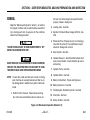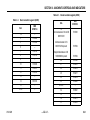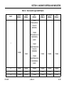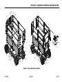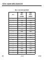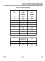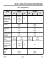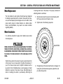
1
Operation and Safety Manual
Original Instructions - Keep this manual with the machine at all times.
Model
3369LE/4069LE
M3369/M4069
ANSI
P/N - 3121220
®
December 10, 2010
FOREWORD
FOREWORD
This manual is a very important tool! Keep it with the machine at all times.
The purpose of this manual is to provide owners, users, operators, lessors, and lessees with the precautions and
operating procedures essential for the safe and proper machine operation for its intended purpose.
Due to continuous product improvements, JLG Industries, Inc. reserves the right to make specification changes
without prior notification. Contact JLG Industries, Inc. for updated information.
3121220
– JLG Lift –
a
FOREWORD
SAFETY ALERT SYMBOLS AND SAFETY SIGNAL WORDS
This is the Safety Alert Symbol. It is used to alert you to the potential personal
injury hazards. Obey all safety messages that follow this symbol to avoid possible
injury or death
INDICATES AN IMMINENTLY HAZARDOUS SITUATION. IF NOT
AVOIDED, WILL RESULT IN SERIOUS INJURY OR DEATH. THIS DECAL
WILL HAVE A RED BACKGROUND.
INDICATES A POTENTIALITY HAZARDOUS SITUATION. IF NOT
AVOIDED, COULD RESULT IN SERIOUS INJURY OR DEATH. THIS
DECAL WILL HAVE AN ORANGE BACKGROUND.
b
INDICATES A POTENTIALITY HAZARDOUS SITUATION. IF NOT
AVOIDED, MAY RESULT IN MINOR OR MODERATE INJURY. IT MAY
ALSO ALERT AGAINST UNSAFE PRACTICES. THIS DECAL WILL HAVE
A YELLOW BACKGROUND.
NOTICE
INDICATES INFORMATION OR A COMPANY POLICY THAT RELATES
DIRECTLY OR INDIRECTLY TO THE SAFETY OF PERSONNEL OR PROTECTION OF PROPERTY.
– JLG Lift –
3121220
FOREWORD
For:
THIS PRODUCT MUST COMPLY WITH ALL SAFETY RELATED BULLETINS. CONTACT JLG INDUSTRIES, INC. OR THE LOCAL AUTHORIZED
JLG REPRESENTATIVE FOR INFORMATION REGARDING SAFETYRELATED BULLETINS WHICH MAY HAVE BEEN ISSUED FOR THIS
PRODUCT.
• Accident Reporting
• Product Safety Publications
• Current Owner Updates
• Questions Regarding
Product Safety
NOTICE
JLG INDUSTRIES, INC. SENDS SAFETY RELATED BULLETINS TO THE
OWNER OF RECORD OF THIS MACHINE. CONTACT JLG INDUSTRIES,
INC. TO ENSURE THAT THE CURRENT OWNER RECORDS ARE
UPDATED AND ACCURATE.
NOTICE
JLG INDUSTRIES, INC. MUST BE NOTIFIED IMMEDIATELY IN ALL
INSTANCES WHERE JLG PRODUCTS HAVE BEEN INVOLVED IN AN
ACCIDENT INVOLVING BODILY INJURY OR DEATH OF PERSONNEL
OR WHEN SUBSTANTIAL DAMAGE HAS OCCURRED TO PERSONAL
PROPERTY OR THE JLG PRODUCT.
• Standards and Regulations
Compliance Information
• Questions Regarding Special Product Applications
• Questions Regarding Product Modifications
Contact:
Product Safety and Reliability Department
JLG Industries, Inc.
13224 Fountainhead Plaza
Hagerstown, MD 21742
or Your Local JLG Office
(See addresses on manual rear cover)
In USA:
Toll Free:
877-JLG-SAFE (877-554-7233)
Outside USA:
Phone:
E-mail:
3121220
– JLG Lift –
240-420-2661
[email protected]
c
FOREWORD
REVISION LOG
Original Issue
Revised
Revised
Revised
Revised
Revised
d
- May 5, 2005
- May 24, 2005
- August 11, 2006
- March 29, 2007
- May 21, 2008
- December 10, 2010
– JLG Lift –
3121220
TABLE OF CONTENTS
SECTION - PARAGRAPH, SUBJECT
PAGE
SECTION - PARAGRAPH, SUBJECT
SECTION - 1 - SAFETY PRECAUTIONS
1.1
1.2
1.3
1.4
1.5
2.2
GENERAL . . . . . . . . . . . . . . . . . . . . . . . . . . . . . . . . .1-1
PRE-OPERATION . . . . . . . . . . . . . . . . . . . . . . . . . . .1-1
Operator Training and Knowledge . . . . . . . . . . . .1-1
Workplace Inspection . . . . . . . . . . . . . . . . . . . . . .1-2
Machine Inspection . . . . . . . . . . . . . . . . . . . . . . .1-3
OPERATION . . . . . . . . . . . . . . . . . . . . . . . . . . . . . . .1-3
General . . . . . . . . . . . . . . . . . . . . . . . . . . . . . . . . .1-3
Trip and Fall Hazards . . . . . . . . . . . . . . . . . . . . . .1-4
Electrocution Hazards . . . . . . . . . . . . . . . . . . . . .1-5
Tipping Hazards . . . . . . . . . . . . . . . . . . . . . . . . . .1-7
Crushing and Collision Hazards. . . . . . . . . . . . . .1-8
TOWING, LIFTING, AND HAULING . . . . . . . . . . . . .1-9
MAINTENANCE . . . . . . . . . . . . . . . . . . . . . . . . . . . .1-9
General . . . . . . . . . . . . . . . . . . . . . . . . . . . . . . . . .1-9
Maintenance Hazards. . . . . . . . . . . . . . . . . . . . .1-10
Battery Hazards . . . . . . . . . . . . . . . . . . . . . . . . .1-10
2.3
2.4
3121220
PREPARATION, INSPECTION, AND
MAINTENANCE. . . . . . . . . . . . . . . . . . . . . . . . . . . . 2-2
PRE-START INSPECTION. . . . . . . . . . . . . . . . . . . . 2-4
Preparing the Machine for Operation . . . . . . . . . 2-5
Function Check . . . . . . . . . . . . . . . . . . . . . . . . . . 2-5
OSCILLATING AXLE LOCKOUT TEST
(IF EQUIPPED) . . . . . . . . . . . . . . . . . . . . . . . . . . . . 2-7
GENERAL . . . . . . . . . . . . . . . . . . . . . . . . . . . . . . 2-9
Limit Switch Locations. . . . . . . . . . . . . . . . . . . . 2-11
SECTION - 3 - MACHINE CONTROLS AND INDICATORS
3.1
3.2
GENERAL . . . . . . . . . . . . . . . . . . . . . . . . . . . . . . . .
CONTROLS AND INDICATORS . . . . . . . . . . . . . . .
Ground Control Station . . . . . . . . . . . . . . . . . . . .
Platform Control Station . . . . . . . . . . . . . . . . . . .
3-1
3-1
3-1
3-3
SECTION - 4 - MACHINE OPERATION
4.1
4.2
SECTION - 2 - USER RESPONSIBILITIES, MACHINE
PREPARATION AND INSPECTION
2.1
PAGE
PERSONNEL TRAINING . . . . . . . . . . . . . . . . . . . . .2-1
Operator Training . . . . . . . . . . . . . . . . . . . . . . . . .2-1
Training Supervision. . . . . . . . . . . . . . . . . . . . . . .2-1
Operator Responsibility . . . . . . . . . . . . . . . . . . . .2-1
– JLG Lift –
4.3
4.4
4.5
DESCRIPTION. . . . . . . . . . . . . . . . . . . . . . . . . . . . .
POWER SELECT. . . . . . . . . . . . . . . . . . . . . . . . . . .
Platform/Ground Select. . . . . . . . . . . . . . . . . . . .
RAISING AND LOWERING . . . . . . . . . . . . . . . . . . .
Raising & Lowering . . . . . . . . . . . . . . . . . . . . . . .
LEVELING JACKS . . . . . . . . . . . . . . . . . . . . . . . . . .
PLATFORM EXTENSION . . . . . . . . . . . . . . . . . . . .
4-1
4-1
4-1
4-1
4-1
4-2
4-2
i
TABLE OF CONTENTS
SECTION - PARAGRAPH, SUBJECT
PAGE
4.6
PLATFORM HANDRAILS FOLD DOWN
PROCEDURE (IF EQUIPPED) . . . . . . . . . . . . . . . . . 4-2
4.7 STEERING . . . . . . . . . . . . . . . . . . . . . . . . . . . . . . . . 4-2
Traveling Forward and Reverse. . . . . . . . . . . . . 4-4
4.8 SHUT DOWN AND PARK . . . . . . . . . . . . . . . . . . . . 4-4
4.9 SAFETY PROP . . . . . . . . . . . . . . . . . . . . . . . . . . . . . 4-5
4.10 BATTERY CHARGING PROCEDURE . . . . . . . . . . . 4-5
4.11 TIE DOWN/LIFTING . . . . . . . . . . . . . . . . . . . . . . . . . 4-5
Tie Down . . . . . . . . . . . . . . . . . . . . . . . . . . . . . . . 4-5
Lifting . . . . . . . . . . . . . . . . . . . . . . . . . . . . . . . . . . 4-5
SECTION - PARAGRAPH, SUBJECT
SECTION - 6 - GENERAL SPECIFICATIONS AND
OPERATOR MAINTENANCE
6.1
6.2
6.3
SECTION - 5 - EMERGENCY PROCEDURES
5.1
5.2
5.3
5.4
5.5
PAGE
GENERAL . . . . . . . . . . . . . . . . . . . . . . . . . . . . . . . . 5-1
INCIDENT NOTIFICATION. . . . . . . . . . . . . . . . . . . . 5-1
EMERGENCY TOWING PROCEDURES . . . . . . . . . 5-1
MANUAL DESCENT SYSTEM . . . . . . . . . . . . . . . . . 5-2
EMERGENCY OPERATION . . . . . . . . . . . . . . . . . . . 5-2
Operator Unable to Control Machine . . . . . . . . . 5-2
Platform Caught Overhead . . . . . . . . . . . . . . . . . 5-2
6.4
6.5
INTRODUCTION. . . . . . . . . . . . . . . . . . . . . . . . . . . .6-1
SUPPLEMENTAL INFORMATION . . . . . . . . . . . . . .6-1
OPERATING SPECIFICATIONS . . . . . . . . . . . . . . . .6-2
Dimensional Data . . . . . . . . . . . . . . . . . . . . . . . . .6-5
Capacities . . . . . . . . . . . . . . . . . . . . . . . . . . . . . . .6-5
Tires . . . . . . . . . . . . . . . . . . . . . . . . . . . . . . . . . . .6-6
Engine. . . . . . . . . . . . . . . . . . . . . . . . . . . . . . . . . .6-7
Batteries (Electric Machines) . . . . . . . . . . . . . . . .6-7
Critical Stability Weights . . . . . . . . . . . . . . . . . . . .6-8
Lubrication . . . . . . . . . . . . . . . . . . . . . . . . . . . . .6-11
OPERATOR MAINTENANCE . . . . . . . . . . . . . . . . .6-12
TIRES AND WHEELS . . . . . . . . . . . . . . . . . . . . . . .6-14
Tire Damage . . . . . . . . . . . . . . . . . . . . . . . . . . . .6-14
Tire Replacement . . . . . . . . . . . . . . . . . . . . . . . .6-14
Wheel Replacement . . . . . . . . . . . . . . . . . . . . . .6-15
Wheel Installation . . . . . . . . . . . . . . . . . . . . . . . .6-15
SECTION - 7 - INSPECTION AND REPAIR LOG
ii
– JLG Lift –
3121220
TABLE OF CONTENTS
SECTION - PARAGRAPH, SUBJECT
PAGE
SECTION - PARAGRAPH, SUBJECT
LIST OF FIGURES
2-1.
2-2.
2-3.
2-4.
3-1.
3-2.
3-3.
3-4.
3-5.
3-6.
4-1.
4-2.
4-3.
6-1.
6-2.
6-3.
3121220
PAGE
LIST OF TABLES
Walk-Around Inspection (Sheet 1 of 3) . . . . . . . . . .2-8
Walk-Around Inspection (Sheet 2 of 3) . . . . . . . . . .2-9
Walk-Around Inspection (Sheet 3 of 3) . . . . . . . . .2-10
Limit Switch Locations . . . . . . . . . . . . . . . . . . . . . .2-11
Ground Control Station . . . . . . . . . . . . . . . . . . . . . .3-2
Platform Control Station. . . . . . . . . . . . . . . . . . . . . .3-6
Indicator Panel . . . . . . . . . . . . . . . . . . . . . . . . . . . . .3-7
Decal Installation (ANSI) . . . . . . . . . . . . . . . . . . . . .3-8
Decal Installation (ANSI Export). . . . . . . . . . . . . . .3-11
Decal Installation (CE/AUS) . . . . . . . . . . . . . . . . . .3-17
Grade and Sideslope . . . . . . . . . . . . . . . . . . . . . . . .4-3
Lifting & Tie Down Chart - Sheet 1 of 2 . . . . . . . . . .4-6
Lifting & Tie Down Chart - Sheet 2 of 2 . . . . . . . . . .4-7
Engine Operating Temperature Specifications (Kubota) Sheet 1 of 2 . . . . . . . . . . . . . . . . . . . . . . . .6-9
Engine Operating Temperature Specifications (Kubota) Sheet 2 of 2 . . . . . . . . . . . . . . . . . . . . . . .6-10
Operator Maintenance and Lubrication Diagram .6-12
– JLG Lift –
1-1
2-1
2-2
2-3
3-1
3-2
3-3
6-1
6-2
6-3
6-4
6-5
6-6
6-7
6-8
6-9
6-10
6-11
7-1
Minimum Approach Distances (M.A.D.) . . . . . . . . . 1-6
Inspection and Maintenance Table. . . . . . . . . . . . . 2-3
Drive Limits . . . . . . . . . . . . . . . . . . . . . . . . . . . . . . . 2-6
Tilt vs. Height. . . . . . . . . . . . . . . . . . . . . . . . . . . . . . 2-6
Decal Location Legend (ANSI) . . . . . . . . . . . . . . . . 3-9
Decal Location Legend (ANSI Export) . . . . . . . . . 3-12
Decal Location Legend (CE/AUS) . . . . . . . . . . . . 3-18
Operating Specifications. . . . . . . . . . . . . . . . . . . . . 6-2
Dimensional Data . . . . . . . . . . . . . . . . . . . . . . . . . . 6-5
Capacities . . . . . . . . . . . . . . . . . . . . . . . . . . . . . . . . 6-5
Tire Specifications. . . . . . . . . . . . . . . . . . . . . . . . . . 6-6
Engine Specifications . . . . . . . . . . . . . . . . . . . . . . . 6-7
Engine Battery Specifications . . . . . . . . . . . . . . . . . 6-7
Battery Specifications . . . . . . . . . . . . . . . . . . . . . . . 6-7
Critical Stability Weights . . . . . . . . . . . . . . . . . . . . . 6-8
Hydraulic Oil . . . . . . . . . . . . . . . . . . . . . . . . . . . . . 6-11
Lubrication Specifications. . . . . . . . . . . . . . . . . . . 6-11
Wheel Torque Chart . . . . . . . . . . . . . . . . . . . . . . . 6-16
Inspection and Repair Log . . . . . . . . . . . . . . . . . . . 7-1
iii
TABLE OF CONTENTS
SECTION - PARAGRAPH, SUBJECT
PAGE
SECTION - PARAGRAPH, SUBJECT
PAGE
This page left blank intentionally.
iv
– JLG Lift –
3121220
SECTION 1 - SAFETY PRECAUTIONS
SECTION 1. SAFETY PRECAUTIONS
1.1
GENERAL
This section outlines the necessary precautions for proper
and safe machine usage and maintenance. In order to promote proper machine usage, it is mandatory that a daily routine is established based on the content of this manual. A
maintenance program, using the information provided in this
manual and the Service and Maintenance Manual, must also
be established by a qualified person and must be followed to
ensure that the machine is safe to operate.
FAILURE TO COMPLY WITH THE SAFETY PRECAUTIONS LISTED IN
THIS MANUAL COULD RESULT IN MACHINE DAMAGE, PROPERTY
DAMAGE, PERSONAL INJURY OR DEATH.
1.2
PRE-OPERATION
Operator Training and Knowledge
The owner/user/operator/lessor/lessee of the machine
should not accept operating responsibility until this manual
has been read, training is accomplished, and operation of
the machine has been completed under the supervision of
an experienced and qualified operator.
• The Operators and Safety Manual must be read in its
entirety before operating the machine. For clarification,
questions, or additional information regarding any portions of this manual, contact JLG Industries, Inc.
These sections contain the responsibilities of the owner,
user, operator, lessor, and lessee concerning safety, training,
inspection, maintenance, application, and operation.If there
are any questions with regard to safety, training, inspection,
maintenance, application, and operation, please contact JLG
Industries, Inc. (“JLG”).
3121220
– JLG Lift –
1-1
SECTION 1 - SAFETY PRECAUTIONS
• An operator must not accept operating responsibilities
until adequate training has been given by competent and
authorized persons.
• Allow only those authorized and qualified personnel to
operate the machine who have demonstrated that they
understand the safe and proper operation and maintenance of the unit.
• Before operation, check work area for overhead hazards
such as electric lines, bridge cranes, and other potential
overhead obstructions.
• Read, understand, and obey all DANGERS, WARNINGS,
CAUTIONS, and operating instructions on the machine
and in this manual.
• Check floor surfaces for holes, bumps, drop-offs, obstructions, debris, concealed holes, and other potential hazards.
• Ensure that the machine is to be used in a manner which
is within the scope of its intended application as determined by JLG.
• Check the work area for hazardous locations. Do not
operate the machine in hazardous environments unless
approved for that purpose by JLG.
• All operating personnel must be familiar with the emergency controls and emergency operation of the machine
as specified in this manual.
• Ensure that the ground conditions are adequate to support the maximum tire load indicated on the tire load
decals located on the chassis adjacent to each wheel.
• Read, understand, and obey all applicable employer,
local, and governmental regulations as they pertain to
your utilization and application of the machine.
• Do not operate the machine when wind conditions exceed
28 mph (12.5 m/s).
Workplace Inspection
• Precautions to avoid all hazards in the work area must be
taken by the user before operation of the machine.
1-2
• Do not operate or raise the platform from a position on
trucks, trailers, railway cars, floating vessels, scaffolds or
other equipment unless the application is approved in
writing by JLG.
• This machine can be operated in nominal ambient temperatures of 0o F to 104o F (-20o C to 40o C). Consult JLG
to optimize operation outside of this temperature range.
– JLG Lift –
3121220
SECTION 1 - SAFETY PRECAUTIONS
Machine Inspection
1.3
• Do not operate this machine until the inspections and
functional checks have been performed as specified in
Section 2 of this manual.
OPERATION
General
• Do not operate this machine until it has been serviced and
maintained according to the maintenance and inspection
requirements as specified in the machine’s Service and
Maintenance Manual.
• Ensure all safety devices are operating properly. Modification of these devices is a safety violation.
• Do not use the machine for any purpose other than positioning personnel, their tools, and equipment.
• Before operation, the user must be familiar with the
machine capabilities and operating characteristics of all
functions.
• Never operate a malfunctioning machine. If a malfunction
occurs, shut down the machine. Remove the unit from
service and notify the proper authorities.
• Do not remove, modify, or disable any safety devices.
MODIFICATION OR ALTERATION OF AN AERIAL WORK PLATFORM
SHALL BE MADE ONLY WITH PRIOR WRITTEN PERMISSION FROM THE
MANUFACTURER
• Do not operate any machine on which the safety or
instruction placards or decals are missing or illegible.
• Check the machine for modifications to original components. Ensure that any modifications have been approved
by JLG.
• Avoid accumulation of debris on platform deck. Keep
mud, oil, grease, and other slippery substances from footwear and platform deck.
3121220
– JLG Lift –
• Never slam a control switch or lever through neutral to an
opposite direction. Always return switch to neutral and
stop before moving the switch to the next function. Operate controls with slow and even pressure.
• Hydraulic cylinders, other than the outrigger cylinders,
should never be left at end of travel (fully extended or fully
retracted) before shutdown or for long periods of time.
Always “bump” control in opposite direction slightly when
function reaches end of travel. This applies both to
machines in operation or in the stowed position.
1-3
SECTION 1 - SAFETY PRECAUTIONS
• Do not allow personnel to tamper with or operate the
machine from the ground with personnel in the platform,
except in an emergency.
• Do not carry materials directly on platform railing unless
approved by JLG.
• When two or more persons are in the platform, the operator shall be responsible for all machine operations.
Trip and Fall Hazards
• JLG Industries, Inc. recommends that all persons in the
platform wear a full body harness with a lanyard attached
to an authorized lanyard anchorage point while operating
this machine. For further information regarding fall protection requirements on JLG products, contact JLG Industries, Inc.
• Always ensure that power tools are properly stowed and
never left hanging by their cord from the platform work
area.
• Do not assist a stuck or disabled machine by pushing or
pulling except by pulling at the chassis tie-down lugs.
• Stow scissor arm assembly and shut off all power before
leaving machine.
1-4
• Prior to operation, ensure all gates and rails are fastened
and secured in their proper position. Identify the designated lanyard anchorage point(s) at the platform and
securely attach the lanyard. Attach only one (1) lanyard
per lanyard anchorage point
– JLG Lift –
3121220
SECTION 1 - SAFETY PRECAUTIONS
Electrocution Hazards
.
• This machine is not insulated and does not provide protection from contact or proximity to electrical current.
• Keep both feet firmly positioned on the platform floor at all
times. Never position ladders, boxes, steps, planks, or
similar items on unit to provide additional reach for any
purpose.
• Never use the scissor arm assembly to gain access to or
leave the platform.
• Use extreme caution when entering or leaving platform.
Ensure that the scissor arm assembly is fully lowered.
Face the machine when entering or leaving the platform.
Always maintain “three point contact” with the machine,
using two hands and one foot or two feet and one hand at
all times during entry and exit.
• Keep oil, mud, and slippery substances cleaned from footwear and the platform floor.
3121220
– JLG Lift –
1-5
SECTION 1 - SAFETY PRECAUTIONS
Table 1-1.Minimum Approach Distances (M.A.D.)
• Maintain safe clearance from electrical lines, apparatus, or
any energized (exposed or insulated) parts in accordance
with the Minimum Approach Distance (MAD) as specified
in Table 1-1.
• Allow for machine movement and electrical line swaying.
1-6
Voltage Range
(Phase to Phase)
MINIMUM APPROACH DISTANCE
in Feet (Meters)
0 to 50KV
10 (3)
Over 50V to 200 KV
15 (5)
Over 200KV to 350 KV
20 (6)
Over 350 KV to 500 KV
25 (8)
Over 500 KV to 750 KV
35 (11)
Over 750 KV to 1000 KV
45 (14)
NOTE:
This requirement shall apply except where
employer, local or governmental regulations
are more stringent.
• Maintain a clearance of at least 10 ft. (3m) between any
part of the machine and its occupants, their tools, and
their equipment from any electrical line or apparatus carrying up to 50,000 volts. One foot additional clearance is
required for every additional 30,000 volts or less.
– JLG Lift –
3121220
SECTION 1 - SAFETY PRECAUTIONS
• The minimum approach distance may be reduced if insulating barriers are installed to prevent contact, and the
barriers are rated for the voltage of the line being guarded.
These barriers shall not be part of (or attached to) the
machine. The minimum approach distance shall be
reduced to a distance within the designed working dimensions of the insulating barrier. This determination shall be
made by a qualified person in accordance with the
employer, local, or governmental requirements for work
practices near energized equipment.
.
DO NOT MANEUVER MACHINE OR PERSONNEL INSIDE PROHIBITED
ZONE (MAD). ASSUME ALL ELECTRICAL PARTS AND WIRING ARE
ENERGIZED UNLESS KNOWN OTHERWISE.
Tipping Hazards
• Ensure that the ground conditions are adequate to support the maximum tire load indicated on the tire load
decals located on the chassis adjacent to each wheel. Do
not travel on unsupported surfaces.
• The user should be familiar with the driving surface before
driving. Do not exceed the allowable sideslope and grade
while driving
3121220
– JLG Lift –
• Do not elevate platform or drive with platform elevated
while on or near a sloping, uneven, or soft surface. Ensure
machine is positioned on a firm, level and uniformly supported surface before elevating platform or driving with
the platform in the elevated position.
• Before driving on floors, bridges, trucks, and other surfaces, check allowable capacity of the surfaces.
• Never exceed the maximum work load as specified on the
platform. Keep all loads within the confines of the platform, unless authorized by JLG.
1-7
SECTION 1 - SAFETY PRECAUTIONS
• Keep the chassis of the machine a minimum of 2 ft (0.6 m)
from holes, bumps, drop-offs, obstructions, debris, concealed holes, and other potential hazards at the ground
level.
• Watch for obstructions around machine and overhead
when driving. Check clearances above, on sides, and bottom of platform when lifting or lowering platform.
• Never attempt to use the machine as a crane. Do not tieoff machine to any adjacent structure. Never attach wire,
cable, or any similar items to platform.
• Do not cover the platform sides or carry large surface-area
items in the platform when operating outdoors. The addition of such items increases the exposed wind area of the
machine.
• Do not increase the platform size with unauthorized deck
extensions or attachments.
• If scissor arm assembly or platform is caught so that one
or more wheels are off the ground, all persons must be
removed before attempting to free the machine. Use
cranes, forklift trucks, or other appropriate equipment to
stabilize machine and remove personnel.
Crushing and Collision Hazards
• Approved head gear must be worn by all operating and
ground personnel.
• Keep hands and limbs out of the scissor arm assembly
during operation.
1-8
• During operation, keep all body parts inside platform railing.
• Always post a lookout when driving in areas where vision
is obstructed.
• Keep non-operating personnel at least 6 ft (1.8 m) away
from machine during all driving operations.
• Under all travel conditions, the operator must limit travel
speed according to conditions of ground surface, congestion, visibility, slope, location of personnel, and other factors causing hazards of collision or injury to personnel.
– JLG Lift –
3121220
SECTION 1 - SAFETY PRECAUTIONS
• Ensure platform is fully retracted and completely empty of
tools prior to towing, lifting or hauling.
• Be aware of stopping distances in all drive speeds. When
driving in high speed, switch to low speed before stopping. Travel grades in low speed only.
• When lifting machine with a forklift, position forks only at
designated areas of the machine. Lift with a forklift of adequate capacity.
• Do not use high speed drive in restricted or close quarters
or when driving in reverse.
• Refer to Section 4 for lifting information.
• Exercise extreme caution at all times to prevent obstacles
from striking or interfering with operating controls and persons in the platform.
• Ensure that operators of other overhead and floor level
machines are aware of the aerial work platform’s presence. Disconnect power to overhead cranes. Barricade
floor area if necessary.
• Avoid operating over ground personnel. Warn personnel
not to work, stand, or walk under a raised platform. Position barricades on floor as necessary.
1.4
TOWING, LIFTING, AND HAULING
• Never allow personnel in platform while towing, lifting, or
hauling.
1.5
MAINTENANCE
General
This section contains general safety precautions which must be
observed during maintenance of this machine. Additional precautions to be observed during machine maintenance are
inserted at the appropriate points in this maunual and in the Service and Maintenance Manual. It is of utmost importance that
maintenance personnel pay strict attention to these precautions
to avoid possible injury to personnel or damage to the machine
or property. A maintenance program must be established by a
qualified person and must be followed to ensure that the
machine is safe.
• This machine should not be towed, except in the event of
emergency, malfunction, power failure, or loading/unloading. Refer to emergency towing procedures.
3121220
– JLG Lift –
1-9
SECTION 1 - SAFETY PRECAUTIONS
Maintenance Hazards
• Shut off power to all controls and ensure that all operating
systems are secured from inadvertent motion prior to performing any adjustments or repairs.
• Never work under an elevated platform until it has been
fully lowered to the full down position, if possible, or otherwise supported and restrained from movement with
appropriate safety props, blocking, or overhead supports.
• Always relieve hydraulic pressure from all hydraulic circuits before loosening or removing hydraulic components.
• Always disconnect batteries when servicing electrical
components or when performing welding on the machine.
• Shut down the engine (if equipped) while fuel tanks are
being filled.
• Ensure replacement parts or components are identical or
equivalent to original parts or components.
• Never attempt to move heavy parts without the aid of a
mechanical device. Do not allow heavy objects to rest in
an unstable position. Ensure adequate support is provided when raising components of the machine.
• Remove all rings, watches, and jewelry when performing
any maintenance. Do not wear loose fitting clothing or
1-10
long hair unrestrained which may become caught or
entangled in equipment.
• Use only clean approved non-flammable cleaing solvents.
• Never alter, remove, or substitute any items such as counterweights, tires, batteries, platforms or other items that
may reduce or affect the overall weight or stability of the
machine.
• Reference the Service and Maintenance Manual for the
weights of critical stability items.
MODIFICATION OR ALTERATION OF AN AERIAL WORK PLATFORM
SHALL BE MADE ONLY WITH PRIOR WRITTEN PERMISSION FROM THE
MANUFACTURER.
Battery Hazards
• Always disconnect batteries when servicing electrical
components or when performing welding on the machine.
• Do not allow smoking, open flame, or sparks near battery
during charging or servicing.
• Do not contact tools or other metal objects across the battery terminals.
– JLG Lift –
3121220
SECTION 1 - SAFETY PRECAUTIONS
• Always wear hand, eye, and face protection when servicing batteries. Ensure that battery acid does not come in
contact with skin or clothing.
BATTERY FLUID IS HIGHLY CORROSIVE. AVOID CONTACT WITH SKIN
AND CLOTHING AT ALL TIMES. IMMEDIATELY RINSE ANY CONTACTED
AREA WITH CLEAN WATER AND SEEK MEDICAL ATTENTION.
• Charge batteries only in a well ventilated area.
• Avoid overfilling the battery fluid level. Add distilled water
to batteries only after the batteries are fully charged.
3121220
– JLG Lift –
1-11
SECTION 1 - SAFETY PRECAUTIONS
NOTES:
1-12
– JLG Lift –
3121220
SECTION 2 - USER RESPONSIBILITIES, MACHINE PREPARATION AND INSPECTION
SECTION 2. USER RESPONSIBILITIES, MACHINE PREPARATION AND INSPECTION
2.1
PERSONNEL TRAINING
6. The safest means to operate the machine where overhead obstructions, other moving equipment, and obstacles, depressions, holes, drop-offs.
The aerial platform is a personnel handling device; so it is
necessary that it be operated and maintained only by trained
personnel.
Persons under the influence of drugs or alcohol or who are
subject to seizures, dizziness or loss of physical control must
not operate this machine.
7. Means to avoid the hazards of unprotected electrical
conductors.
8. Specific job requirements or machine application.
Training Supervision
Operator Training
Training must be done under the supervision of a qualified
person in an open area free of obstructions until the trainee
has developed the ability to safely control and operate the
machine.
Operator training must cover:
1. Use and limitations of the controls in the platform and at
the ground, emergency controls and safety systems.
2. Control labels, instructions, and warnings on the
machine.
Operator Responsibility
3. Rules of the employer and government regulations.
4. Use of approved fall protection equipment.
The operator must be instructed that he/she has the responsibility and authority to shut down the machine in case of a
malfunction or other unsafe condition of either the machine
or the job site.
5. Enough knowledge of the mechanical operation of the
machine to recognize a malfunction or potential malfunction.
3121220
– JLG Lift –
2-1
SECTION 2 - USER RESPONSIBILITIES, MACHINE PREPARATION AND INSPECTION
2.2 PREPARATION, INSPECTION, AND
MAINTENANCE
NOTICE
The following table covers the periodic machine inspections
and maintenance recommended by JLG Industries, Inc.
Consult local regulations for further requirements for aerial
work platforms. The frequency of inspections and maintenance must be increased as necessary when the machine is
used in a harsh or hostile environment, if the machine is
used with increased frequency, or if the machine is used in a
severe manner.
2-2
JLG INDUSTRIES, INC. RECOGNIZES A FACTORY-CERTIFIED SERVICE
TECHNICIAN AS A PERSON WHO HAS SUCCESSFULLY COMPLETED
THE JLG SERVICE TRAINING SCHOOL FOR THE SPECIFIC JLG PRODUCT MODEL.
– JLG Lift –
3121220
SECTION 2 - USER RESPONSIBILITIES, MACHINE PREPARATION AND INSPECTION
Table 2-1.Inspection and Maintenance Table
Type
Frequency
Primary
Responsibility
Service
Qualification
Reference
Pre-Start
Inspection
Before using each day; or
whenever there’s an Operator change.
User or Operator
User or Operator
Operator and Safety Manual
Pre-Delivery
Inspection (See Note)
Before each sale, lease, or rental delivery.
Owner, Dealer, or User
Qualified JLG Mechanic
Service and Maintenance
Manual and applicable JLG
inspection form
Owner, Dealer, or User
Qualified JLG Mechanic
Service and Maintenance
Manual and applicable JLG
inspection form
In service for 3 months or 150 hours, whichever comes first; or
Frequent
Inspection
Out of service for a period of more than 3
months; or
Purchased used.
Annual Machine
Inspection
(See Note)
Annually, no later than 13 months from the
date of prior inspection.
Owner, Dealer, or User
Factory Certified Service
Technician
(Recommended)
Service and Maintenance
Manual and applicable JLG
inspection form
Preventative
Maintenance
At intervals as specified in the Service and
Maintenance Manual.
Owner, Dealer, or User
Qualified JLG Mechanic
Service and Maintenance
Manual
NOTE: Inspection forms are available from JLG. Use the Service and Maintenance Manual to perform inspections.
3121220
– JLG Lift –
2-3
SECTION 2 - USER RESPONSIBILITIES, MACHINE PREPARATION AND INSPECTION
2.3
PRE-START INSPECTION
The Pre-Start Inspection should include each of the following:
1.
2.
Cleanliness – Check all surfaces for leakage (oil, fuel,
or battery fluid) or foreign objects. Report any leakage to
the proper maintenance personnel.
Structure - Inspect the machine structure for dents,
damage, weld or parent metal cracks or other discrepencies.
Parent Metal Crack
3.
2-4
4.
Operators and Safety Manuals – Make sure a copy of
the Operator and Safety Manual is enclosed in the
weather resistant storage container.
5.
“Walk-Around” Inspection – Refer to Figure 2-1., WalkAround Inspection (Sheet 1 of 3).
6.
Battery – Charge as required.
7.
Fuel - (Combustion Engine Powered Machines) – Add
the proper fuel as necessary.
8.
Engine Oil Supply - Ensure that the engine oil level is at
the full mark on the dipstick and the filler cap is secure
9.
Fluid Levels - Be sure to check the engine oil and the
hydraulic oil levels.
10.
Accessories/Attachments - Reference the Operator
and Safety Manual of each attachment or accessory
installed upon the machine for specific inspection, operation, and maintenance instructions.
11.
Function Check – Once the “Walk-Around” Inspection
is complete, perform a functional check of all systems in
an area free of overhead and ground level obstructions.
Refer to Section 4 for more specific instructions on the
operation of each function.
Weld Crack
Decals and Placards – Check all for cleanliness and
legibility. Make sure none of the decals and placards are
missing. Make sure all illegible decals and placards are
cleaned or replaced.
– JLG Lift –
3121220
SECTION 2 - USER RESPONSIBILITIES, MACHINE PREPARATION AND INSPECTION
Preparing the Machine for Operation
Function Check
Emergency Ground Control Station
Perform the Function Check as follows:
1. Turn key-switch to ground control select.
1. From the ground emergency control panel with no load
in the platform:
2. Pull emergency stop switch to the On position.
3. Check the function of the protective scissor cage.
a. Check for proper lifting and lowering of the platform.
Platform Control Box
b. Check manual descent.
1. Ensure the control box is connected at the platform.
c. Ensure that all machine functions are disabled
when the Emergency Stop Button is activated.
2. Complete pre-operational checks:
NOTE:
• Check all functions
• Machine should not be drivable with outriggers
extended.
• Check all limit switches
2. From the platform control console:
a. Ensure that the control console is firmly secured in
the proper location.
• Check the emergency-STOP button
b. Check that all guards protecting the function control
switches are in place.
• Check the automatic self levelling
IF THE MACHINE DOES NOT OPERATE PROPERLY, TURN OFF THE
MACHINE IMMEDIATELY! REPORT THE PROBLEM TO THE PROPER
MAINTENANCE PERSONNEL. DO NOT OPERATE THE MACHINE UNTIL
IT IS DECLARED SAFE FOR OPERATION.
3121220
Be sure the platform extension is retracted before lowereing.
– JLG Lift –
c. Check the high drive cut out switch by raising the
platform beyond the preset high drive speed cutout
height (stowed) and ensure the high drive speed
cuts out.
d. Ensure that all machine functions are disabled
when the Emergency Stop Button is pushed in.
2-5
SECTION 2 - USER RESPONSIBILITIES, MACHINE PREPARATION AND INSPECTION
e. Ensure that all LED’s in the control box are working
properly.
f.
Table 2-3. Tilt vs. Height
Check that the platform extension extends and
retracts properly.
a. Drive the machine on a grade, not to exceed the
rated gradeability, and stop to ensure the brakes
hold.
b. The red warning LED on the control panel indicates
the chassis is on a slope beyond the rated limit from
side to side and/or front to rear when the platform is
in the stowed position.
Table 2-2. Drive Limits
Front - Back
< 25 ft (7.6 m)
5°
5°
< 30 ft (9.1 m)
4°
5°
3°
5°
Full Height
3369LE/M3369 (CSA)
Full Height
3°
3°
3369LE/M3369 (CE) - 37 mph (16.7 m/s) windspeed option
< 25 ft (7.6 m)
4°
5°
Full Height
2°
4°
4069LE/M4069 (ANSI/CE/Australia/Japan)
High Drive
Cutout
Drive Cutout
Drive at Creep
Speed
3369LE/M3369
Above Stowed
N/A
N/A
4069LE/M4069
Above Stowed
30 ft (9.1 m)
N/A
M4069 (AUS Full
Drive Height Model)
Above Stowed
N/A
28 ft - 30 ft
(8.5 m - 9.1 m)
< 30 ft (9.1 m)
5°
5°
< 36 ft (11 m)
4°
5°
Full Height
3°
5°
4069LE/M4069 (CSA)
Full Height
NOTE:
2-6
Left - Right
3369LE/M3369 (ANSI/CE/Australia/Japan)
3. With the platform in the stowed position:
Model
Tilt
Height
– JLG Lift –
3°
3°
When the limits are exceeded, drive and lift-up functions
are cutout.
3121220
SECTION 2 - USER RESPONSIBILITIES, MACHINE PREPARATION AND INSPECTION
2.4
OSCILLATING AXLE LOCKOUT TEST (IF
EQUIPPED)
7. Lower the machine platform; the lockout cylinder should
then release and allow wheel to rest on the ground. It
may be necessary to activate DRIVE to release cylinders.
NOTICE
LOCKOUT SYSTEM TEST MUST BE PERFORMED QUARTERLY, ANY
TIME A SYSTEM COMPONENT IS REPLACED, OR WHEN IMPROPER
SYSTEM OPERATION IS SUSPECTED.
NOTE:
Ensure platform is fully lowered prior to beginning lockout
cylinder test.
8. Place the 6 inch (15.2 cm) high block with ascension
ramp in front of right front wheel.
9. From platform control station, select LOW drive speed.
10. Place DRIVE control switch to FORWARD position and
carefully drive the machine up ascension ramp until right
front wheel is on top of block.
1. Place a 6 inch (15.2 cm) high block with ascension ramp
in front of left front wheel.
11. Raise machine platform approximately 7 ft (2.1 m) on
the 3369LE or 9 ft (2.7 m) on the 4069LE.
2. From platform control station, select LOW drive speed.
12. Place DRIVE control switch to REVERSE position and
carefully drive the machine off the block and ramp.
3. Place DRIVE control switch to FORWARD position and
carefully drive the machine up ascension ramp until left
front wheel is on top of block.
4. Raise machine platform approximately 7 ft (2.1 m) on
the 3369LE or 9 ft (2.7 m) on the 4069LE.
5. Place DRIVE control switch to REVERSE position and
carefully drive the machine off the block and ramp.
6. Have an assistant check to see that the left front wheel
remains locked in position off the ground.
3121220
– JLG Lift –
13. Have an assistant check to see that the right front wheel
remains locked in position off the ground.
14. Lower the machine platform; the lockout cylinder should
then release and allow wheel to rest on the ground. It
may be necessary to activate DRIVE to release cylinders.
15. If the lockout cylinders do not function properly, have
qualified personnel correct the malfunction prior to any
further operation.
2-7
SECTION 2 - USER RESPONSIBILITIES, MACHINE PREPARATION AND INSPECTION
26
27
4
25
24
23
22
9
21
20
12
19
4
18
17
16
2
15
1
2
14
3
4
5
6
7
8
9
10 11
4
12
13
Figure 2-1. Walk-Around Inspection (Sheet 1 of 3)
2-8
– JLG Lift –
3121220
SECTION 2 - USER RESPONSIBILITIES, MACHINE PREPARATION AND INSPECTION
GENERAL
Begin the “Walk-Around Inspection” at Item 1, as noted on
the diagram. Continue Left (counterclockwise viewed from
top) checking each item in sequence for the conditions
listed in the following checklist.
TO AVOID POSSIBLE INJURY, BE SURE MACHINE POWER IS “OFF”
DURING “WALK-AROUND INSPECTION”.
NOTICE
DO NOT OVERLOOK VISUAL INSPECTION OF CHASSIS UNDERSIDE.
CHECKING THIS AREA OFTEN RESULTS IN DISCOVERY OF CONDITIONS WHICH COULD CAUSE EXTENSIVE MACHINE DAMAGE.
NOTE:
On each item, make sure there are no loose or missing
parts, that they are securely fastened, and that no visible damage exists in addition to any other criteria mentioned.
trol lever lock and emergency stop switch function
properly, manual in storage box.
2. Leveling Jacks - See Note
3. Spindle, Tie Rod and Steer Linkage (left front) - See
Note
4. Wheels and Tires -Properly secured, no missing lug
nuts. Refer to section 6, Tires and Wheels. Inspect
wheels for damage and corrosion
5. Steer Cylinder - See Note
6. Hydraulic Reservoir - Recommended hydraulic fluid
level on level indicator on tank. Breather cap secure
and working.
7. Hydraulic Pump - See Note
8. Hydraulic Motor - See Note
9. Battery Compartment - Proper electrolyte level.
10. Battery Disconnect - See Note
11. Oscillating Axle, Oscillation Cylinder - See Note
1. Platform Control Console - Placard secure and legible, control lever and switches return to neutral, con-
12. Drive Hubs - See Note
13. Brake, Left Rear - See Note
Figure 2-2. Walk-Around Inspection (Sheet 2 of 3)
3121220
– JLG Lift –
2-9
SECTION 2 - USER RESPONSIBILITIES, MACHINE PREPARATION AND INSPECTION
14. Limit Switch - See Note
23. Ground Controls - Placard secure and legible, control
switches return to neutral position, emergency stop
switch functions properly. Control markings legible.
15. Ladder - See Note
16. Manual Descent - See Note
17. Limit Switch - See Note
24. Control Valve - No unsupported wires or hoses; no
damaged or broken wires.
18. Brake, Right Rear - See Note
25. Sizzor Arms and Sliding Wear Pads - See Note
19. Oscillation Cylinder - See Note
26. Spindle, Tie Rod and Steer Linkage (right front) - See
Note
20. Battery Disconnect - See Note
27. Battery Charger - See Note
21. Lift Cylinder - See Note
22. Generator Fuel Supply - See Note
28. Platform/Handrail Installation (Not Shown) - See Note
Figure 2-3. Walk-Around Inspection (Sheet 3 of 3)
2-10
– JLG Lift –
3121220
SECTION 2 - USER RESPONSIBILITIES, MACHINE PREPARATION AND INSPECTION
Limit Switch Locations
1
1. Proximity Sensor Switch
2. Rotary Angle Sensor Switch
2
Figure 2-4. Limit Switch Locations
3121220
– JLG Lift –
2-11
SECTION 2 - USER RESPONSIBILITIES, MACHINE PREPARATION AND INSPECTION
NOTES:
2-12
– JLG Lift –
3121220
SECTION 3 - MACHINE CONTROLS AND INDICATORS
SECTION 3. MACHINE CONTROLS AND INDICATORS
3.1
GENERAL
1. Power/Emergency Stop
A two-position red mushroom shaped switch furnishes
power to Platform/Ground Select switch when pulled out
(on). When pushed in (off), power is shut off to the Platform/Ground Select switch.
NOTICE
THE MANUFACTURER HAS NO DIRECT CONTROL OVER MACHINE
APPLICATION AND OPERATION. THE USER AND OPERATOR ARE
RESPONSIBLE FOR CONFORMING WITH GOOD SAFETY PRACTICES.
2. Platform/Ground Select
This section provides the necessary information needed to
understand control functions.
3.2
A three position, key operated switch supplies power to
platform control console when positioned to platform.
With the key held in the ground position, power is shut
off to platform and only ground controls are operable.
CONTROLS AND INDICATORS
Ground Control Station
NOTE:
DO NOT OPERATE FROM GROUND CONTROL STATION WITH PERSONNEL IN PLATFORM EXCEPT IN AN EMERGENCY.
NOTE:
When machine is shut down, the ground control emergency stop switch must be positioned to OFF to prevent
draining the batteries.
With Platform/Ground Select in center position, power is
shut off to controls at both operating stations.
3. Lift/Lower
A three position, momentary contact lift control switch
provides raising and lowering of the platform when positioned to up or down.
4. Generator Start Switch (Optional)
A momentary contact, push button switch is provided to
manually start the optional generator
3121220
– JLG Lift –
3-1
SECTION 3 - MACHINE CONTROLS AND INDICATORS
.
PLATFORM/GROUND
SELECT SWITCH
CIRCUIT
BREAKER
EMERGENCY
STOP SWITCH
HOURMETER
PLATFORM
OVERLOAD
INDICATOR
GENERATOR
SWITCH
SYSTEM
FAULT
LIFT
SWITCH
Figure 3-1. Ground Control Station
3-2
– JLG Lift –
3121220
SECTION 3 - MACHINE CONTROLS AND INDICATORS
A two-position red mushroom shaped switch furnishes
power to Platform/Ground Select switch when pulled out
(on). When pushed in (off), power is shut off to the Platform/Ground Select switch.
5. Platform Overload Indicator (If Equipped)
Indicates the platform has been overloaded. An audible
alarm will also signal when the plaform is overloaded.
NOTE:
If the Overload Indicator is illuminated, all functions will be
prevented from the platform controls. Using the ground
controls or manual descent, fully lower the machine and
reduce the weight in the platform so as to not exceed the
rated workload indicated on the capacity decal.
2. Controller (Joystick)
The Joystick controls four functions: drive, steer, lift and
optional outriggers. The drive or the lift function switch
must be selected before operating the joystick. The controller is ‘ramped’ to allow variable speed.
6. Hourmeter
3. Steer
The hourmeter indicates the number of hours the
machine has been operated.
Steering is controlled by a thumb-operated switch on
top of the Joystick.
7. Circuit Breaker
4. Low/High Speed
If the circuit breaker opens this indicates a short or overload on the machine.
The two position speed switch controls high or low
range travel speed.
8. System Fault
NOTE:
Illuminates when there is any type of fault in the electrical system.
Platform Control Station
Travel speed will automatically be reduced to low drive
when the platform is raised above the stowed position.
For M4069 (AUS Full Drive Height Model), low drive
speed is cut back to creep drive speed above 28 - 30 ft
(8.5 - 9.1 m) up to the maximum height of 40 ft (12.2 m).
1. Power/Emergency Stop
3121220
– JLG Lift –
3-3
SECTION 3 - MACHINE CONTROLS AND INDICATORS
5. Drive Select
When selected, the drive function will be active for 3 seconds. The operator has 3 seconds to select the desired
direction of travel.
When selected, the leveling jack function will be active
for 3 seconds in order to raise or lower the jacks. Indicator lights will illuminate signaling the leveling jacks are
being set or retracted. See Figure 3-3., Indicator Panel
8. Generator Enable Switch (Optional)
The Generator Enable Switch, when in the off position,
allows the operator to prevent the generator engine from
starting when using the machine indoors. When in the
on position (and the ground Emergency Stop Switch on
[pulled out]), the generator is enabled to automatically
start when the batteries need charged.
DO NOT OPERATE MACHINE IF HIGH DRIVE SPEED OPERATES WHEN
PLATFORM IS RAISED ABOVE THE STOWED POSITION. FOR AUS FULL
DRIVE HEIGHT MODEL, DO NOT OPERATE IF LOW DRIVE SPEED IS
NOT CUT BACK TO CREEP DRIVE SPEED ONCE PLATFORM IS RAISED
ABOVE 28 - 30 FT (8.5 - 9.1 M)
9. All Wheel Drive (Optional)
6. Lift /Lower
Activating the All Wheel Drive switch allows the operator
to engage the front drive motors for a pre-set time of 10
seconds. The control system may also engage the positrack function automatically. This occurs when the rear
wheels begin to slip and the joystick is engaged at 75%.
This is pre-set to remain engaged for 10 seconds.
When selected, the lift function will be active for 3 seconds. The operator has 3 seconds to select the desired
direction of lift.
DO NOT LOWER WITHOUT COMPLETELY RETRACTING THE PLATFORM
EXTENSION.
7. Leveling Jacks (Optional, Mandatory on M4069 AUS Full
Drive Height Model)
3-4
NOTE:
All Wheel Drive does not aid in climbing a grade.
10. Horn
– JLG Lift –
If pressed, this switch supplies power to the horn.
3121220
SECTION 3 - MACHINE CONTROLS AND INDICATORS
11. Tilt Indicator Warning LED
The red warning LED on the control panel the illuminates when the chassis is on a slope greater than what
the machine is programmed for.
12. Tilt Alarm Warning Horn
The Tilt Alarm Warning Horn is activated when the chassis is on a slope greater than what the machine is programmed for and the platform is elevated.
13. Battery Charge Indicator
This indicates the level of charge remaining in the batteries.
3121220
– JLG Lift –
3-5
SECTION 3 - MACHINE CONTROLS AND INDICATORS
All Wheel
Drive
1705911B
Platform
Overload
LED
B
Horn
A
A
Enable
Trigger
Drive
Selector
Power/
Emergency
Stop
Steer
Button
Leveling
Jacks
Generator
Enable Switch
1705912B
Speed
Selector
Lift
Selector
Joystick
Figure 3-2. Platform Control Station
3-6
– JLG Lift –
3121220
SECTION 3 - MACHINE CONTROLS AND INDICATORS
LIFT
BATTERY CHARGE
INDICATOR
TILT
SYSTEM
FAULT
DRIVE
LEVELING
JACKS
(SET)
LEVELING
JACKS
(RETRACTED)
Figure 3-3. Indicator Panel
3121220
– JLG Lift –
3-7
SECTION 3 - MACHINE CONTROLS AND INDICATORS
2 19
3
103
38
39
105
10
36
24
23
23
107
9
106
107
110
1
16
17
106
20
22
110
108
13
15
110
111
105
7
14
11
108
34
111
37
21
12
102
37
40
25
22
8
9
40
37105
113
109
111
34
20
37
5
112
4
41
108
20
22
Figure 3-4. Decal Installation (ANSI)
3-8
– JLG Lift –
3121220
SECTION 3 - MACHINE CONTROLS AND INDICATORS
Table 3-1. Decal Location Legend (ANSI)
Table 3-1. Decal Location Legend (ANSI)
3121220
Item
ANSI
0270591-6
1-3
--
4
1700584
5
1701644
6
--
7
1702153
8
Item
ANSI
0270591-6
19
USA manufactured - Prior to S/N
0200101481
1703788
USA manufactured - S/N
0200101481to present
1701509
1702155
Belgium Manufactured - S/N
1200000398 to present
1701509
9
--
20
1701500
10
1703816
21
1703812
11
1704211
22
1703814
12
1704412
23
1704277
13
--
24
1703819
14
3251813
25
1703822
15
--
26 to 33
--
16-18
--
34
1703687
35
--
36
1704911
37
1703818
– JLG Lift –
3-9
SECTION 3 - MACHINE CONTROLS AND INDICATORS
Table 3-1. Decal Location Legend (ANSI)
Item
ANSI
0270591-6
38
1703821
39
1704903
40
1703813
41
1704248
101
--
102
1704174
103
(M3369/M4069
ANSI California Spec only)
3-10
Table 3-1. Decal Location Legend (ANSI)
Item
1702962
104
--
105
3369LE & M3369
4069LE & M4069
1001125438
1001125437
106
(4WD only)
1704998
107
3369LE
4069LE
M3369
M4069
1704783
1704784
1704908
1704909
– JLG Lift –
ANSI
0270591-6
108
3369LE & M3369
4069LE & M4069
1703490
1704953
109
(M3369/M4069 only)
1704286
110
1702773
111
1704885
112
1704830
113
(M3369/M4069 only)
1701505
3121220
SECTION 3 - MACHINE CONTROLS AND INDICATORS
105
36 10
39
JAPAN
SPEC ONLY
ALL SPEC
EXCEPT JAPAN
36
38
24
23
23
2 19
3
107
110
106
107
6
13
20
22
1
16
17
106
9
110
108
13
15
109
110
105
7
14
11
108
34
111
37
21
12
102
37
40
25
22
8
20
9
40
37
105 113
109
111
34
4
37
5
112
108
41
20
22
Figure 3-5. Decal Installation (ANSI Export)
3121220
– JLG Lift –
3-11
SECTION 3 - MACHINE CONTROLS AND INDICATORS
Table 3-2. Decal Location Legend (ANSI Export)
Item #
Chinese
0272005_2
CSA
0272653_2
Japanese
0270602_2
Latin American
0270600_5
Korea
0275688_2
1-3
--
--
--
--
--
--
4
1700584
1700584
1700584
1700584
1700584
1700584
5
1701644
1701644
1701644
1701644
1701644
1701644
3252191
3252191
--
3252191
3252191
1705303
1705303
--
1705303
1705303
3252191
3252191
--
3252191
3252191
1705303
1705303
--
1705303
1705303
6
USA manufactured - Prior to
S/N 0200108331
USA manufactured - S/N
0200108331to present
Belgium manufactured Prior to S/N 1200000459
Belgium Manufactured - S/N
1200000459 to present
3-12
Brazilian
0270601_5
– JLG Lift –
3252191
1705303
3252191
1705303
3121220
SECTION 3 - MACHINE CONTROLS AND INDICATORS
Table 3-2. Decal Location Legend (ANSI Export)
Item #
Brazilian
0270601_5
Chinese
0272005_2
CSA
0272653_2
Japanese
0270602_2
Latin American
0270600_5
Korea
0275688_2
1701621
1704006
1703962
1702155
1702155
1702155
1704007
(USA manufactured Prior to S/N
0200108331)
1704006
(USA manufactured - S/
N 0200108331to
present)
7
1704008
1704007
(Belgium manufactured Prior to S/N
1200000459)
1704607
1704006
(Belgium Manufactured S/N 1200000459 to
present)
8
3121220
1702155
1702155
1702155
9
1702631
1702631
1702631
1702631
1702631
1702631
10
1704699
1705195
1704684
1704278
1704691
1707021
– JLG Lift –
3-13
SECTION 3 - MACHINE CONTROLS AND INDICATORS
Table 3-2. Decal Location Legend (ANSI Export)
Item #
Brazilian
0270601_5
Chinese
0272005_2
CSA
0272653_2
Japanese
0270602_2
Latin American
0270600_5
Korea
0275688_2
11
1704211
1704211
1704211
1704211
1704211
1704211
12
1704412
1704412
1704412
1704412
1704412
1704412
13
--
--
--
--
--
--
14
3251813
3251813
3251813
3251813
3251813
3251813
15
3252645
3252645
3252645
3252645
3252645
3252645
16-17
--
--
--
--
--
--
18
2901912
2901912
2901912
2901912
2901912
2901912
19
USA manufactured - Prior to
S/N 0200101481
1703788
1703788
1703788
1703788
1703788
1703788
1701509
1701509
1701509
1701509
1701509
1701509
USA manufactured - S/N
0200101481to present
Belgium Manufactured - S/N
1200000398 to present
3-14
1701509
1701509
1701509
1701509
1701509
1701509
20
1703811
1703811
1703811
1703811
1703811
1703811
21
1703812
1703812
1703812
1703812
1703812
1703812
22
1703814
1703814
1703814
1703814
1703814
1703814
– JLG Lift –
3121220
SECTION 3 - MACHINE CONTROLS AND INDICATORS
Table 3-2. Decal Location Legend (ANSI Export)
Item #
Brazilian
0270601_5
Chinese
0272005_2
CSA
0272653_2
Japanese
0270602_2
Latin American
0270600_5
Korea
0275688_2
23
1704277
1704277
1704277
1704277
1704277
1704277
24
1703819
1703819
1703819
1703819
1703819
1703819
25
1703822
1703822
1703822
1703822
1703822
1703822
26-33
--
--
--
--
--
--
34
1703687
1703687
1703687
1703687
1703687
1703687
35
--
--
--
--
--
36
1704915
1705097
1704904
1704917
1704913
1707026
37
1704701
1705193
1704686
1705394
1704693
1707018
38
1704702
1705194
1704687
1705398
1704694
1707020
39
1704916
1705098
1704912
1704918
1704914
1707024
40
1704341
1704344
1704340
1704342
1704339
1707022
41
1704330
1704333
1704329
1704331
1704329
1707025
101
--
--
--
--
--
--
102
1704174
1704174
1704174
1704174
1704174
1704174
103-104
--
--
--
--
--
--
105
3369LE & M3369
4069LE & M4069
3121220
1001125438
1001125437
– JLG Lift –
3-15
SECTION 3 - MACHINE CONTROLS AND INDICATORS
Table 3-2. Decal Location Legend (ANSI Export)
Brazilian
0270601_5
Chinese
0272005_2
CSA
0272653_2
Japanese
0270602_2
Latin American
0270600_5
Korea
0275688_2
106
(4WD only)
1704998
1704998
1704998
1704998
1704998
1704998
107
3369LE
4069LE
M3369
M4069
1704783
1704784
1704908
1704909
1704783
1704784
1704908
1704909
1704783
1704784
1704908
1704909
1704783
1704784
1704908
1704909
1704783
1704784
1704908
1704909
1704783
1704784
1704908
1704909
108
3369LE & M3369
4069LE & M4069
1703490
1704953
1703490
1704953
1703490
1704953
1703490
1704953
1703490
1704953
1703490
1704953
109
(M3369/M4069 only)
1704373
--
1704368
1704369
1704371
--
110
1702773
1702773
1702773
1702773
1702773
1702773
111
1704885
1704885
1704885
1704885
1704885
1704885
112
(M3369/M4069 only)
1704830
1704830
1704830
1704830
1704830
1704830
113
1701505
1701505
1701505
1701505
1701505
1701505
Item #
3-16
– JLG Lift –
3121220
SECTION 3 - MACHINE CONTROLS AND INDICATORS
40
6
24
23
19
7
7
36
9
14
8
11
41
25
41
37
33 42
21
37
12
33
36
41
20
36
4
22
38 5
41
36
20 22
8
Figure 3-6. Decal Installation (CE/AUS)
3121220
– JLG Lift –
3-17
SECTION 3 - MACHINE CONTROLS AND INDICATORS
Table 3-3. Decal Location Legend (CE/AUS)
3-18
Item #
CE/AUS
0275084_2
3369LE/4069LE
CE/AUS
0275085_2
M3369/M4069
1-3
--
--
4
1700584
1700584
5
1701644
1701644
6
1706338
1706338
7
--
1705084
8
1702155
1702155
9
1702631
1702631
10
--
--
11
1704211
1704211
12
1704412
1704412
13 - 17
--
--
18
2901912
2901912
19
1701509
1701509
20
1703811
1703811
21
1703812
1703812
22
1703814
1703814
23
1704277
1704277
– JLG Lift –
3121220
SECTION 3 - MACHINE CONTROLS AND INDICATORS
Table 3-3. Decal Location Legend (CE/AUS)
3121220
Item #
CE/AUS
0275084_2
3369LE/4069LE
CE/AUS
0275085_2
M3369/M4069
24
1703819
1703819
25
1703822
1703822
26 - 32
--
--
33
1703687
1703687
34 - 35
--
--
36
1706338
1706338
37
1705670
1705670
38
1706492
1706492
39
--
--
40
1704530 (3369LE & M3369)
1706491 (3369LE only)
1704580
41
1703490 (3369LE & M3369)
1704953 (4069LE & M4069)
42
1704174
1704174
– JLG Lift –
3-19
SECTION 3 - MACHINE CONTROLS AND INDICATORS
NOTES:
3-20
– JLG Lift –
3121220
SECTION 4 - MACHINE OPERATION
SECTION 4. MACHINE OPERATION
4.1
DESCRIPTION
4.2
POWER SELECT
This machine is a self-propelled hydraulic lift equipped with a
work platform on an elevating scissor mechanism. Vibrations
emitted by these machines are not hazardous to an operator
in the work platform. The equivalent continuous A-Weighted
sound pressure level at the work platform is less than 70
dB(A).
Platform/Ground Select
The primary operator control station is in the platform. From
this control station, the operator can drive and steer the
machine in both forward and reverse directions. The
machine has a Ground Control Station which will override
the Platform Control Station. Ground Controls operate lift
and lower and are to be used in an emergency to lower the
platform to the ground should the operator in the platform be
unable to do so. Ground Control is also to be used in PreStart Inspection.
4.3
The Platform/Ground Select switch directs power to the
Ground or Platform controls as selected. For power, the
POWER/EMERGENCY STOP switch must also be pulled out
(on).
RAISING AND LOWERING
Raising & Lowering
To raise or lower the platform, either use Lift or Lower function and hold switch until desired elevation is reached.
DO NOT LOWER WITHOUT COMPLETELY RETRACTING PLATFORM
EXTENSION.
3121220
– JLG Lift –
4-1
SECTION 4 - MACHINE OPERATION
4.4
LEVELING JACKS
3. Remove the pin from extension right side handrail, lift up
and fold down onto platform deck.
Once the leveling jacks leave the stowed position (fully
retracted) but are not fully extended, the lift and drive functions are cut out.
4. Remove the two pins from rear handrail, lift up and fold
gate down onto platform deck.
5. Lift up left handrail, fold handrail down onto platform
deck.
After all 4 jacks are extended and touch a solid surface only
the drive function is cut out. Drive function is restored once
the jacks are stowed (fully retracted) again.
4.5
PLATFORM EXTENSION
The machine is equipped with a mechanically extendible
deck. To extend the deck, lift handle up on the left and right
side of the platform to release the latch and use the handle to
push the extendible deck out. When the deck reaches the
end of its travel, push handle down to latch, this will lock and
hold the deck in place. To retract the deck, reverse operation.
4.6
PLATFORM HANDRAILS FOLD DOWN
PROCEDURE (IF EQUIPPED)
6. Lift up right handrail, fold handrail down onto platform
deck.
4.7
STEERING
Position thumb switch on drive/lift/steer controller to right for
steering right, or to left for steering left.
TO AVOID LOSS OF TRAVEL CONTROL OR UPSET ON GRADES AND
SIDE SLOPES, DO NOT DRIVE MACHINE ON GRADES OR SIDE SLOPES
EXCEEDING THOSE SPECIFIED ON WARNING PLACARD AT PLATFORM.
1. Remove the two pins from platform extension gate and
fold gate to the left side handrail.
2. Remove the pin from extension left side handrail, lift up
and fold down handrail onto platform deck.
4-2
– JLG Lift –
3121220
SECTION 4 - MACHINE OPERATION
Figure 4-1. Grade and Sideslope
3121220
– JLG Lift –
4-3
SECTION 4 - MACHINE OPERATION
4.8
Traveling Forward and Reverse
1. At platform controls, pull out emergency stop switch and
select the drive switch.
2. Position drive controller to forward or reverse as desired.
DIRECTION OF DRIVE AND STEER MOVEMENT MAY BE OPPOSITE
FROM NORMAL OPERATION. BEFORE DRIVING, LOCATE THE BLACK/
WHITE ORIENTATION ARROWS ON BOTH THE CHASSIS AND THE
PLATFORM CONTROLS. MOVE THE DRIVE CONTROLS IN A DIRECTION
MATCHING THE ORIENTATION ARROWS.
REV
SHUT DOWN AND PARK
NOTE:
When parking overnight, batteries should be charged
properly to ensure readiness for next workday.
To shut down and park the machine, the procedures are as
follows:
1. Drive machine to a reasonably well protected area.
2. Ensure platform is fully lowered.
3. Push in the Emergency Stop at platform controls.
4. Push in the Emergency Stop at ground controls. Position platform/ground select switch to center off.
5. If necessary, cover Platform Controls to protect instruction placards, warning decals and operating controls
from hostile environment.
FWD
6. Chock at least two wheels when parking machine for an
extended period of time.
IF TILT ALARM IS ON WHEN PLATFORM IS RAISED, STOP DRIVING AND
LOWER PLATFORM COMPLETELY, THEN REPOSITION MACHINE SO
THAT IT IS LEVEL BEFORE RAISING PLATFORM.
4-4
– JLG Lift –
3121220
SECTION 4 - MACHINE OPERATION
4.9
SAFETY PROP
4.11 TIE DOWN/LIFTING
Tie Down
1. Place platform in stowed position and retract deck
extension.
SAFETY PROP MUST BE USED WHEN MAINTENANCE REQUIRES SIZZOR ARMS TO BE RAISED.
1. To engage safety prop, raise platform, pull ring to
release safety prop, then rotate prop clockwise until it
hangs vertically. Lower the platform until the safety prop
rests between the two extended cross-shafts.
2. To store safety prop, reverse operation of step 1.
2. Remove all loose items from machine.
3. Secure the chassis using straps or chains of adequate
strength.
Lifting
NOTE:
4.10 BATTERY CHARGING PROCEDURE
The battery charger receptacle is located at the front of the
machine. The receptacle is located in the molded front panel.
1. Place platform in stowed position and retract deck
extension.
1. Connect the charger receptacle to a 115 volt (220 volt)
power outlet with a 15 amp minimum capacity.
2. Remove all loose items from machine.
3. Properly adjust rigging to prevent damage to machine
and so machine remains level.
2. The batteries are charged fully when the 100% LED is lit.
At this time, the charger will shut off automatically.
NOTE:
Discharged batteries will take approximately 23 hours to
charge.
3121220
See manufacturer’s nameplate for gross weight of
machine as originally manufactured.
NOTICE
DO NOT ATTEMPT TO LIFT MACHINE WITH A FORK TRUCK. FORK
POCKETS LOCATED UNDER BATTERY PACKS ARE PROVIDED FOR
LIFTING BATTERIES ONLY.
– JLG Lift –
4-5
SECTION 4 - MACHINE OPERATION
X
MODEL
Z
FRONT AXLE REAR AXLE
(lb)
(lb)
GVW WHEELBASE
lb)
(in)
X
(in)
Z
(in)
3369LE
4860
4900
9760
91.5
45.5
30
4069LE
5300
5260
10,560
91.5
45.9
30
Figure 4-2. Lifting & Tie Down Chart - Sheet 1 of 2
4-6
– JLG Lift –
3121220
SECTION 4 - MACHINE OPERATION
MACHINE WITHOUT LEVELING JACKS
MACHINE WITH LEVELING JACKS
Figure 4-3. Lifting & Tie Down Chart - Sheet 2 of 2
3121220
– JLG Lift –
4-7
SECTION 4 - MACHINE OPERATION
NOTES:
4-8
– JLG Lift –
3121220
SECTION 5 - EMERGENCY PROCEDURES
SECTION 5. EMERGENCY PROCEDURES
5.1
GENERAL
5.3
This section explains the steps to be taken in case of an
emergency situation while operating.
5.2
INCIDENT NOTIFICATION
Towing this machine is prohibited. However, provisions for
moving the machine have been incorporated. The following
procedures are to be used ONLY for emergency.
1. Chock wheels securely.
JLG Industries, Inc. must be notified immediately of any incident involving a JLG product. Even if no injury or property
damage is evident, the factory should be contacted by telephone and provided with all necessary details.
2. Engage the brake release on both drive hubs by loosening the bolts, completely reversing hub caps, and
retightening the bolts.
3. Connect towing equipment and remove chocks.
JLG Phone: 717-485-5161
Failure to notify the manufacturer of an incident involving a
JLG Industries product within 48 hours of such an occurrence may void any warranty consideration on that particular
machine.
NOTICE
FOLLOWING ANY ACCIDENT, THOROUGHLY INSPECT THE MACHINE
AND TEST ALL FUNCTIONS FIRST FROM THE GROUND CONTROLS,
THEN FROM THE PLATFORM CONTROLS.
3121220
EMERGENCY TOWING PROCEDURES
– JLG Lift –
After towing machine, complete the following procedure:
1. Position machine on a firm level surface.
2. Chock wheels securely.
3. Disengage the brake release on both drive hubs by
loosening the bolts, completely reversing hub caps, and
retightening the bolts.
4. Remove chocks.
5-1
SECTION 5 - EMERGENCY PROCEDURES
5.4
MANUAL DESCENT SYSTEM
5.5
The manual descent system is used, in the event of total
power failure, to lower the platform using gravity. Pull the
handle located at the rear of the machine just behind the ladder.
MANUAL DESCENT ON THE 4069LE DOES NOT COMPLETELY LOWER
THE PLATFORM. TO LOWER COMPLETELY, USE THE LOWER FUNCTION AT THE GROUND CONTROL. THE PLATFORM WILL LOWER THE
LAST SEVERAL INCHES (CM) AT GRAVITY SPEED. KEEP CLEAR OF
DESCENDING PLATFORM.
EMERGENCY OPERATION
Operator Unable to Control Machine
NOTE:
If the platform operator is pinned, trapped or unable to
operate or control machine:
1. Other personnel should operate the machine from
ground controls only as required.
2. Other qualified personnel on the platform may use the
platform controls. DO NOT CONTINUE OPERATION IF
CONTROLS DO NOT FUNCTION PROPERLY.
3. Cranes, forklift trucks or other equipment which may be
available are to be used to remove platform occupants
and stabilize motion of the machine.
Platform Caught Overhead
If the platform or boom becomes jammed or snagged in
overhead structures or equipment, rescue platform occupants prior to freeing the machine.
5-2
– JLG Lift –
3121220
SECTION 6 - GENERAL SPECIFICATIONS AND OPERATOR MAINTENANCE
SECTION 6. GENERAL SPECIFICATIONS AND OPERATOR MAINTENANCE
6.1
INTRODUCTION
6.2
SUPPLEMENTAL INFORMATION
This section of the manual provides additional necessary
information to the operator for proper operation and maintenance of this machine.
The following information is provided in accordance with the
requirements of the European Machinery Directive 2006/42/EC
and is only applicable to CE machines.
The maintenance portion of this section is intended as information to assist the machine operator to perform daily maintenance tasks only, and does not replace the more thorough
Preventive Maintenance and Inspection Schedule included
in the Service and Maintenance Manual.
For electric powered machines, the equivalent continuous AWeighted sound pressure level at the work platform is less than
70dB(A).
Other Publications Available Specific to this Machine:
Service and Maintenance Manual (Domestic) .. 3121122
Illustrated Parts Manual (Domestic)................... 3121123
Service and Maintenance Manual (CE .............. 3121824
Illustrated Parts Manual (CE) ............................. 3121825
3121220
For combustion engine powered machines, guaranteed Sound
Power Level (LWA) per European Directive 2000/ 14/EC (Noise
Emission in the Environment by Equipment for Use Outdoors)
based on test methods in accordance with Annex III, Part B,
Method 1 and 0 of the directive, is 109 dB.
The vibration total value to which the hand-arm system is subjected does not exceed 2,5 m/s2. The highest root mean square
value of weighted acceleration to which the whole body is subjected does not exceed 0,5 m/s2.
– JLG Lift –
6-1
SECTION 6 - GENERAL SPECIFICATIONS AND OPERATOR MAINTENANCE
6.3
OPERATING SPECIFICATIONS
Table 6-1. Operating Specifications
Description
3369LE/M3369
ANSI
Max. Number of Persons
Max. Workload (Capacity)
Extension Only:
ANSI/CSA/Brazil:
CE/AUS:
ANSI/CSA/Brazil:
CE/AUS:
Max. Gradeability
Max. Slope (Left - Right)
(optional for CE machines
with 37 mph (16.7 m/s) windspeed rating only)
Max. Slope (Front - Back)
6-2
CE/AUS
CSA
ANSI
2
Max. Platform Height
Max. Slope (Left - Right)
4069LE/M4069
ANSI/CSA/Brazil:
CE/AUS:
ANSI/CSA/Brazil:
CE/AUS:
800 lbs (363kg)
800 lbs (360kg)
250 lbs (113kg)
250 lbs (120kg)
33 ft (10.06m)
40 ft (12.2 m)
35%
35%
4° Up to 25 ft
(7.6 m)
2° Up to 33 ft
(10 m)
5° Up to 33 ft (10 m)
CSA
2
1000 lbs (454kg)
1000 lbs (450kg)
250 lbs (113kg)
250 lbs (120kg)
5° Up to 25 ft (7.6 m)
4° Up to 30 ft (9.1 m)
3° Up to 33 ft (10 m)
NA
CE/AUS
3° Up to 33 ft
(10 m)
NA
3° Up to 33 ft
(10 m)
– JLG Lift –
5° Up to 30 ft (9.1 m)
4° Up to 36 ft (11 m)
3° Up to 40 ft (12.2 m)
3° Up to 40 ft
(12.2 m)
NA
5° Up to 40 ft (12.2 m)
3° Up to 40 ft
(12.2 m)
3121220
SECTION 6 - GENERAL SPECIFICATIONS AND OPERATOR MAINTENANCE
Table 6-1. Operating Specifications
Description
Max. Slope (Front - Back)
(optional forCE machines
with 37 mph (16.7 m/s) windspeed rating only)
3369LE/M3369
4069LE/M4069
ANSI
CE
AUS
NA
5° Up to 25 ft
(7.6 m)
4° Up to 33 ft
(10 m)
NA
ANSI
CE
AUS
NA
Max. Tire Load
3200 lbs
(1452 kg)
3700 lbs
(1680 kg)
Max. Ground Bearing
Pressure
57 psi
(4 kg/cm2)
61 psi
(4.3 kg/cm2)
Max. Allowable Wind Speed
(Standard rating)
28 mph
(12.5 m/s)
28 mph
(12.5 m/s)
Maximum Horizontal Manual
Side Force
667 N
(150 lb force))
Max. Allowable Wind Speed
(16.7 m/s machines only)
(Optional rating for CE Specification only)
NA
Turning Radius:
Inside
Outside
3121220
400 N
(90 lb force)
16.7m/s
(37 mph)
534 N
(120 lb force)
NA
7.5 ft (2.3 m)
16 ft (4.9 m)
– JLG Lift –
400N
(90 lb force)
NA
7.5 ft (2.3 m)
16 ft (4.9 m)
6-3
SECTION 6 - GENERAL SPECIFICATIONS AND OPERATOR MAINTENANCE
Table 6-1. Operating Specifications
Description
3369LE/M3369
ANSI
Wheelbase
Gross Machine Weight
(Approximate)
4069LE/M4069
CE
AUS
ANSI
CE
91.5 in (2.3m)
9,760 lbs
(4,427 kg)
AUS
91.5 in (2.3 m)
10,060 lbs
(4563 kg)
10,560 lbs
(4,790 kg)
11,500 lbs
(5216.3)
Maximum Drive Speed
3 mph (4.8 kmh)
3 mph (4.8 kmh)
Drive Speed - (reduced)
16 - 24 sec/50 ft (15 m)
16 - 24 sec/50 ft (15 m)
10.6 - 12 sec/50 ft (15 m)
10.6 - 12 sec/50 ft (15 m)
Drive Speed - (high)
Drive Speed - (creep)
(AUS Full drive height model)
NA
142 -146 sec/25
ft (7.6 m)
NA
Platform Lift Up Speed
(platform empty)
36 - 40 sec
52 - 60 sec
Platform Lowering Speed
(platform empty)
43 - 48 sec
49 - 51 sec
Max Operating Hydraulic
Pressure
3000 psi (207 bar)
3000 psi (207 bar)
Electrical System Voltage
48 volt
48 volt
8 in (20 cm)
8 in (20 cm)
Ground Clearance
6-4
– JLG Lift –
3121220
SECTION 6 - GENERAL SPECIFICATIONS AND OPERATOR MAINTENANCE
Dimensional Data
Capacities
Table 6-2. Dimensional Data
Transport Height
(rails down)
Table 6-3. Capacities
3369LE/M3369
4069LE/M4069
76.5 in (1.9 m)
79 in (2 m)
Machine Length
121 in (3.1 m)
Machine Width
69 in (1.75 m)
3121220
– JLG Lift –
Fuel Tank - (M Models only)
Hydraulic Tank
Approx. 0.9 gal (3.3 l)
8.25 gal (31.2 l)
Hydraulic System
8.5 gal(32.1 l)
Generator Crankcase
1.2 qts(1.1 l)
6-5
SECTION 6 - GENERAL SPECIFICATIONS AND OPERATOR MAINTENANCE
Tires
Table 6-4. Tire Specifications
Size
240/55 D17.5 R4 Tread
(Fill tire with high durometer polyurethane at 90 psi)
IN240/55-17.5 FF
27.2/10.5-15 FF Turf
IN240/55-17.5
Non Marking
Load Rating
7960 lbs @ 95 psi
(3611kg @ 655kPa)
7730 lbs @ 90 psi
(3506kg @ 621 kPa)
8550 lbs @ 105 psi
(3878kg @ 724kPa)
7960 lbs @ 95 psi
(3611kg @ 655kPa)
7730 lbs @ 90 psi
(3506kg @ 621 kPa)
4019 lbs @ 42 psi
(1823kg @ 290 kPa)
2180 lbs @ 32 psi
(989kg @ 221 kPa)
8550 lbs @ 105 psi
(3878kg @ 724kPa)
7960 lbs @ 95 psi
(3611kg @ 655kPa)
7730 lbs @ 90 psi
(3506kg @ 621 kPa)
Ply Rating
12 Ply
10 Ply
6 Ply
10 Ply
Wheel Nut
Torque
6-6
170 ft lbs
(230 Nm)
– JLG Lift –
3121220
SECTION 6 - GENERAL SPECIFICATIONS AND OPERATOR MAINTENANCE
Batteries (Electric Machines)
Critical Stability Weights
Table 6-5. Battery Specifications
Type
Table 6-6. Critical Stability Weights
706HD
EVL16A-A (AGM)
6
6
Reserve Capacity
810 minutes
841 min.
Amp Hour Rating
@ 20 hour rate - 375
@ 20 hour rate - 390
Voltage
NOTICE
JLG MACHINES EQUIPPED WITH DELTA Q BATTERY CHARGERS ARE
DESIGNED FOR THE BEST PERFORMANCE WITH OEM FACTORY
APPROVED BATTERIES.
A P P R O V E D J L G R E P L A C E M E N T B AT T ER IE S A R E AVA IL A B L E
THROUGH JLG' S AFTERMARKET PARTS DISTRIBUTION CENTERS OR
JLG' S AFTERMARKET PROGRAMS. FOR ASSISTANCE WITH PROPER
BATTERY REPLACEMENT, PLEASE CONTACT YOUR LOCAL JLG SUPPORT OFFICE.
BATTERIES APPROVED BY JLG HAVE BEEN TESTED FOR COMPATIBILITY WITH THE ALGORITHM PROGRAMMING OF THE DELTA Q BATTERY
CHARGER TO OPTIMIZE BATTERY LIFE AND MACHINE CYCLE TIMES.
THE USE OF NON APPROVED BATTERIES IN YOUR JLG EQUIPMENT
MAY RESULT IN PERFORMANCE ISSUES OR BATTERY CHARGER
FAULT CODES. JLG ASSUMES NO RESPONSIBILITY FOR SERVICE OR
PERFORMANCE ISSUES ARISING FROM THE USE OF NON APPROVED
BATTERIES.
3121220
– JLG Lift –
COMPONENT
lbs
kg
Platform
780
354
Platform Extension
360
163
Foam Filled Tires
207
94
Batteries (Electric
Machines - Each)
111
50.3
6-7
SECTION 6 - GENERAL SPECIFICATIONS AND OPERATOR MAINTENANCE
Engine
Table 6-7. Engine Specifications
Type
Displacement
18.7 in3 (306cc)
Bore x Stroke
3in x 2.5 in (78mm x 64mm)
Number of cylinders
Horsepower
Fuel Type
6-8
Air Cooled 4 Cycle Deutz Diesel
Table 6-8. Engine Battery Specifications
BCI Group Size
51R
Cranking Performance
550 Amps @ 32° F (0° C)
450 Amps @ 0° F (-18° C)
Reserve Capacity
80 minutes @ 80° F(27° C)
1
6.6HP/3600 rpm (4.9 kw/3600rpm)
Diesel
– JLG Lift –
3121220
SECTION 6 - GENERAL SPECIFICATIONS AND OPERATOR MAINTENANCE
Figure 6-1. Engine Operating Temperature Specifications - (Kubota) Sheet 1 of 2
3121220
– JLG Lift –
6-9
SECTION 6 - GENERAL SPECIFICATIONS AND OPERATOR MAINTENANCE
Figure 6-2. Engine Operating Temperature Specifications - (Kubota) Sheet 2 of 2
6-10
– JLG Lift –
3121220
SECTION 6 - GENERAL SPECIFICATIONS AND OPERATOR MAINTENANCE
Lubrication
NOTE:
Hydraulic Oil
Table 6-9. Hydraulic Oil
HYDRAULIC SYSTEM OPERATING
TEMPERATURE RANGE
SAE VISCOSITY GRADE
0° to +23° F
(-18° to -5° C)
10W
0° to +210° F
(-18° to +100° C)
10W-20, 10W-30
+50° to +210° F
(+10° to +100° C)
20W-20
Lubrication Specifications
Table 6-10. Lubrication Specifications
KEY
NOTE: Hydraulic oils must have anti-wear qualities at least to API
Service Classification GL-3, and sufficient chemical stability for mobile hydraulic system service. JLG Industries
recommends Mobilfluid 424 hydraulic oil, which has an
SAE viscosity index of 152.
NOTE:
When temperatures remain below 20° F (-7° C), JLG
Industries recommends the use of Mobil DTE13.
3121220
Aside from JLG recommendations, it is not advisable to
mix oils of different brands or types, as they may not contain the same required additives or be of comparable viscosities. If use of hydraulic oil other than Mobilfluid 424 is
desired, contact JLG Industries for proper recommendations.
– JLG Lift –
SPECIFICATIONS
MPG
Multipurpose Grease having a minimum dripping
point of 350° F. Excellent water resistance and adhesive qualities, and being of extreme pressure type.
(Timken OK 40 pounds minimum.)
EPGL
Extreme Pressure Gear Lube (oil) meeting API service classification GL-5 or MIL-Spec MIL-L-2105.
EO
Engine (crankcase) Oil. Gas - API SF/SG class, MILL-2104. Diesel - API CC/CD class, MIL-L-2104B/
MIL-L-2104C.
HO
Hydraulic Oil. API service classification GL-3, e.g.
Mobil 424.
6-11
SECTION 6 - GENERAL SPECIFICATIONS AND OPERATOR MAINTENANCE
6.4
OPERATOR MAINTENANCE
1
1. Sliding Wear Pads
2. Engine Compartment
2
3. Wheel Bearings
4. Hydraulic Oil
5. Drive Hub
1
3
4
5
Figure 6-3. Operator Maintenance and Lubrication Diagram
6-12
– JLG Lift –
3121220
SECTION 6 - GENERAL SPECIFICATIONS AND OPERATOR MAINTENANCE
NOTE:
The following numbers correspond to those in Figure 63., Operator Maintenance and Lubrication Diagram.
1. Sliding Wear Pads
Lube Points - 8 Sliding Wear Pads
Lube - MPG
Interval - Every month or 50 hours.
2. Engine Compartment - The engine compartment is
mounted on a sliding tray that pulls out from the front of
the machine.
a. Engine Oil Check/Fill
Capacity - See Engine Manual
Lube - See Engine Manual
Interval - Check level daily; change per manufacturer’s engine manual.
3. Wheel Bearings
Lube Points - Front Wheels (2)
Lube - MPG
Interval - Every 2 years or 1200 hours
4. Hydraulic Oil
Lube Point - Fill Level/Drain Plug
Lube - HO
Interval - Check oil every 10 hours of operation; change
oil every 2 years or 1200 hours of operation.
5. Drive Hub
Lube Point - Fill Plug
Lube - EPGL
Interval - Every 2 years or 1200 hours
b. Air Cleaner
Lube Point - Filter Element
Interval - Check every 3 months or 150 hours;
change every 6 months or 300 hours.
c. Fuel Filter
Lube Point - Filter Element
Interval - Clean every 3 months or 150 hours;
change every 6 months or 300 hours.
3121220
– JLG Lift –
6-13
SECTION 6 - GENERAL SPECIFICATIONS AND OPERATOR MAINTENANCE
6.5
TIRES AND WHEELS
Tire Replacement
Tire Damage
For pneumatic tires, JLG Industries, Inc. recommends that when
any cut, rip, or tear is discovered that exposes sidewall or tread
area cords in the tire, measures must be taken to remove the
JLG product from service immediately. Arrangements must be
made for replacement of the tire or tire assembly.
For polyurethane foam filled tires, JLG Industries, Inc. recommends that when any of the following are discovered, measures
must be taken to remove the JLG product from service immediately and arrangements must be made for replacement of the
tire or tire assembly.
• a smooth, even cut through the cord plies which
exceeds 3 in. (7.5 cm) in total length
• any tears or rips (ragged edges) in the cord plies
which exceeds 1 in. (2.5 cm) in any direction
JLG recommends a replacement tire be the same size, ply and
brand as originally installed on the machine. lease refer to the
JLG Parts Manual for the part number of the approved tires for a
particular machine and model. If not using a JLG approved
replacement tire, we recommend that replacement tires have
the following characteristics:
• Equal or greater ply/load rating and size of original
• Tire tread contact width equal or greater than original
• Wheel diameter, width, and offset dimensions equal to
the original.
Unless specifically approved by JLG Industries Inc. do not
replace a foam filled tire assembly with a pneumatic tire.
When selecting and installing a replacement tire, ensure that
all tires are inflated to the pressure recommended by JLG.
Due to size variations between tire brands, both tires on the
same axle should be the same.
• any punctures which exceed 1 in. (2.5 cm) in diameter
• any damage to the bead area cords of the tire
If a tire is damaged but is within the above noted criteria, the tire
must be inspected on a daily basis to insure the damage has
not propagated beyond the allowable criteria.
6-14
– JLG Lift –
3121220
SECTION 6 - GENERAL SPECIFICATIONS AND OPERATOR MAINTENANCE
Wheel Replacement
mounting stud holes in the wheels. The proper procedure for
attaching wheels is as follows:
The rims installed on each product model have been designed
for stability requirements which consist of track width, tire pressure, and load capacity. Size changes such as rim width, center
piece location, larger or smaller diameter, etc., without written
factory recommendations, may result in an unsafe condition
regarding stability.
1. Start all nuts by hand to prevent cross threading. DO
NOT use a lubricant on threads or nuts.
2. Tighten nuts in the following sequence:
.
Wheel Installation
It is extremely important to apply and maintain proper wheel
mounting torque.
1
8
3
WHEEL NUTS MUST BE INSTALLED AND MAINTAINED AT THE PROPER
TORQUE TO PREVENT LOOSE WHEELS, BROKEN STUDS, AND POSSIBLE DANGEROUS SEPARATION OF WHEEL FROM THE AXLE. BE SURE
TO USE ONLY THE NUTS MATCHED TO THE CONE ANGLE OF THE
WHEEL.
Tighten the lug nuts to the proper torque to prevent wheels from
coming loose. Use a torque wrench to tighten the fasteners. If
you do not have a torque wrench, tighten the fasteners with a
lug wrench, then immediately have a service garage or dealer
tighten the lug nuts to the proper torque. Over-tightening will
result in breaking the studs or permanently deforming the
3121220
– JLG Lift –
6
4
5
7
9
9 LUG PATTERN
2
3. The tightening of the nuts should be done in stages. Following the recommended sequence, tighten the nuts
per wheel torque chart.
6-15
SECTION 6 - GENERAL SPECIFICATIONS AND OPERATOR MAINTENANCE
Table 6-11. Wheel Torque Chart
TORQUE SEQUENCE
1st Stage
2nd Stage
3rd Stage
40-50 ft lbs
(60-70 Nm)
90-105 ft lbs
(125-150 Nm)
145-170 ft lbs
(200-240 Nm)
Wheel nuts should be torqued after first 50 hours of operation and after each wheel removal. Check torque every 3
months or 150 hours of operation.
6-16
– JLG Lift –
3121220
SECTION 7 - INSPECTION AND REPAIR LOG
SECTION 7. INSPECTION AND REPAIR LOG
Table 7-1. Inspection and Repair Log
Date
3121220
Comments
– JLG Lift –
7-1
SECTION 7 - INSPECTION AND REPAIR LOG
Table 7-1. Inspection and Repair Log
Date
7-2
Comments
– JLG Lift –
3121220
TRANSFER OF OWNERSHIP
Title:____________________________________________________________________
Name: ___________________________________________________________________
Who in your organization should we notify?
Country: _________________________ Telephone: (_______) ____________________
_________________________________________________________________________
Address: _________________________________________________________________
Current Owner: ____________________________________________________________
Date of Transfer: _________________________________
Country: _________________________ Telephone: (_______) ____________________
_________________________________________________________________________
Address: _________________________________________________________________
Previous Owner: ___________________________________________________________
Serial Number: ____________________________________________________________
Mfg. Model: _______________________________________________________________
NOTE: Leased or rented units should not be included on this form.
Thank You,
Product Safety & Reliability Department
JLG Industries, Inc.
13224 Fountainhead Plaza
Hagerstown, MD 21742
USA
Telephone: +1-717-485-6591
Fax: +1-301-745-3713
To Product Owner:
If you now own but ARE NOT the original purchaser of the product covered by this
manual, we would like to know who you are. For the purpose of receiving safety-related
bulletins, it is very important to keep JLG Industries, Inc. updated with the current
ownership of all JLG products. JLG maintains owner information for each JLG product
and uses this information in cases where owner notification is necessary.
Please use this form to provide JLG with updated information with regard to the
current ownership of JLG products. Please return completed form to the JLG Product
Safety & Reliability Department via facsimile or mail to address as specified below.
An Oshkosh Corporation Company
Corporate Office
JLG Industries, Inc.
1 JLG Drive
McConnellsburg PA. 17233-9533
USA
(717) 485-5161
(717) 485-6417
3121220
JLG Worldwide Locations
JLG Industries (Australia)
P.O. Box 5119
11 Bolwarra Road
Port Macquarie
N.S.W. 2444
Australia
JLG Latino Americana Ltda.
Rua Eng. Carlos Stevenson,
80-Suite 71
13092-310 Campinas-SP
Brazil
+61 2 65 811111
+55 19 3295 1025
+55 19 3295 0407
+44 (0)161 654 1000
+61 2 65 810122
JLG Deutschland GmbH
Max-Planck-Str. 21
D - 27721 Ritterhude - Ihlpohl
Germany
+49 (0)421 69 350 20
+49 (0)421 69 350 45
JLG Industries (UK) Ltd
Bentley House
Bentley Avenue
Middleton
Greater Manchester
M24 2GP - England
+48 (0)914 320 245
+48 (0)914 358 200
+33 (0)5 53 88 31 70
+33 (0)5 53 88 31 79
+44 (0)161 654 1001
JLG Equipment Services Ltd.
Rm 1107 Landmark North
39 Lung Sum Avenue
Sheung Shui N. T.
Hong Kong
(852) 2639 5783
JLG Industries (Italia) s.r.l.
Via Po. 22
20010 Pregnana Milanese - MI
Italy
+39 029 359 5210
+39 029 359 5845
(852) 2639 5797
JLG Polska
UI. Krolewska
00-060 Warsawa
Poland
JLG France SAS
Z.I. de Baulieu
47400 Fauillet
France
Oshkosh - JLG Singapore T. E. P. Ltd.
29 Tuas Ave 4
Jurong Industrial Estate
639379
Singapore
+65-6591-9030
+65-6591-9031
JLG Industries (Scotland)
Wright Business Centre
1 Lonmay Road
Queenslie, Glasgow G33 4EL
Scotland
+44 (0)141 781 6700
+44 (0)141 773 1907
Plataformas Elevadoras
JLG Iberica, S.L.
Trapadella, 2
P.I. Castellbisbal Sur
08755 Castellbisbal, Barcelona
Spain
+34 93 772 4700
+34 93 771 1762
www.jlg.com
JLG Sverige AB
Enkopingsvagen 150
Box 704
SE - 176 27 Jarfalla
Sweden
+46 (0)850 659 500
+46 (0)850 659 534