1
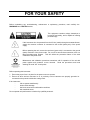
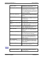
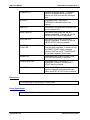
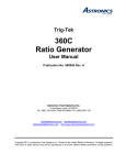
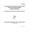
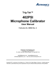
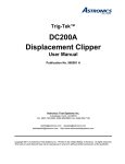
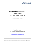
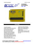
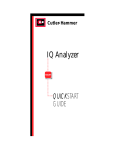
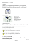
Trig-Tek™
620C
Article Protector
User Manual
Publication No. 981000 Rev. A
Astronics Test Systems Inc.
4 Goodyear, Irvine, CA 92618
Tel: (800) 722-2528, (949) 859-8999; Fax: (949) 859-7139
[email protected] [email protected]
[email protected] http://www.astronicstestsystems.com
Copyright 2014 by Astronics Test Systems Inc. Printed in the United States of America. All rights
reserved. This book or parts thereof may not be reproduced in any form without written permission of the
publisher.
THANK YOU FOR PURCHASING THIS
ASTRONICS TEST SYSTEMS PRODUCT
For this product, or any other Astronics Test Systems product that incorporates software drivers,
you may access our web site to verify and/or download the latest driver versions. The web
address for driver downloads is:
http://www.astronicstestsystems.com/support/downloads
If you have any questions about software driver downloads or our privacy policy, please contact
us at:
[email protected]
WARRANTY STATEMENT
All Astronics Test Systems products are designed to exacting standards and manufactured in full
compliance to our AS9100 Quality Management System processes.
This warranty does not apply to defects resulting from any modification(s) of any product or part
without Astronics Test Systems express written consent, or misuse of any product or part. The
warranty also does not apply to fuses, software, non-rechargeable batteries, damage from battery
leakage, or problems arising from normal wear, such as mechanical relay life, or failure to follow
instructions.
This warranty is in lieu of all other warranties, expressed or implied, including any implied
warranty of merchantability or fitness for a particular use. The remedies provided herein are
buyer’s sole and exclusive remedies.
For the specific terms of your standard warranty, contact Customer Support. Please have the
following information available to facilitate service.
1. Product serial number
2. Product model number
3. Your company and contact information
You may contact Customer Support by:
E-Mail:
Telephone:
Fax:
[email protected]
+1 800 722 3262
(USA)
+1 949 859 7139
(USA)
RETURN OF PRODUCT
Authorization is required from Astronics Test Systems before you send us your product or sub-assembly for
service or calibration. Call or contact Customer Support at 1-800-722-3262 or 1-949-859-8999 or via fax at
1-949-859-7139. We can also be reached at: [email protected].
If the original packing material is unavailable, ship the product or sub-assembly in an ESD shielding bag
and use appropriate packing materials to surround and protect the product.
PROPRIETARY NOTICE
This document and the technical data herein disclosed, are proprietary to Astronics Test Systems, and
shall not, without express written permission of Astronics Test Systems, be used in whole or in part to
solicit quotations from a competitive source or used for manufacture by anyone other than Astronics Test
Systems. The information herein has been developed at private expense, and may only be used for
operation and maintenance reference purposes or for purposes of engineering evaluation and incorporation
into technical specifications and other documents which specify procurement of products from Astronics
Test Systems.
TRADEMARKS AND SERVICE MARKS
All trademarks and service marks used in this document are the property of their respective owners.
•
Racal Instruments, Talon Instruments, Trig-Tek, ActivATE, Adapt-A-Switch, N-GEN, and PAWS are
trademarks of Astronics Test Systems in the United States.
DISCLAIMER
Buyer acknowledges and agrees that it is responsible for the operation of the goods purchased and should
ensure that they are used properly and in accordance with this document and any other instructions
provided by Seller. Astronics Test Systems products are not specifically designed, manufactured or
intended to be used as parts, assemblies or components in planning, construction, maintenance or
operation of a nuclear facility, or in life support or safety critical applications in which the failure of the
Astronics Test Systems product could create a situation where personal injury or death could occur.
Should Buyer purchase Astronics Test Systems product for such unintended application, Buyer shall
indemnify and hold Astronics Test Systems, its officers, employees, subsidiaries, affiliates and distributors
harmless against all claims arising out of a claim for personal injury or death associated with such
unintended use.
FOR YOUR SAFETY
Before undertaking any troubleshooting, maintenance or exploratory procedure, read carefully the
WARNINGS and CAUTION notices.
This equipment contains voltage hazardous to
human life and safety, and is capable of inflicting
personal injury.
If this instrument is to be powered from the AC line (mains) through an autotransformer,
ensure the common connector is connected to the neutral (earth pole) of the power
supply.
Before operating the unit, ensure the conductor (green wire) is connected to the ground
(earth) conductor of the power outlet. Do not use a two-conductor extension cord or a
three-prong/two-prong adapter. This will defeat the protective feature of the third
conductor in the power cord.
Maintenance and calibration procedures sometimes call for operation of the unit with
power applied and protective covers removed. Read the procedures and heed
warnings to avoid “live” circuit points.
Before operating this instrument:
1. Ensure the proper fuse is in place for the power source to operate.
2. Ensure all other devices connected to or in proximity to this instrument are properly grounded or
connected to the protective third-wire earth ground.
If the instrument:
-
fails to operate satisfactorily
shows visible damage
has been stored under unfavorable conditions
has sustained stress
Do not operate until performance is checked by qualified personnel.
Publication No. 981000 Rev. A
620C User Manual
Table of Contents
Chapter 1 .........................................................................................................................1-1
Introduction .....................................................................................................................1-1
Description ..................................................................................................................................... 1-1
Specifications ................................................................................................................................. 1-2
Accel Input .......................................................................................................................... 1-2
Ref Frequency Input ........................................................................................................... 1-2
Compressor Input ............................................................................................................... 1-3
Compressor Output ............................................................................................................ 1-3
Accel Output ....................................................................................................................... 1-3
Velocity Output ................................................................................................................... 1-3
Displacement Output .......................................................................................................... 1-4
Terminals ............................................................................................................................ 1-4
Controls .............................................................................................................................. 1-4
Indicators ............................................................................................................................ 1-5
Dimensions ......................................................................................................................... 1-6
Power Requirement ........................................................................................................... 1-6
Chapter 2 .........................................................................................................................2-1
Operation .........................................................................................................................2-1
Start-Up Procedure ........................................................................................................................ 2-2
Initial Instrument Setup .............................................................................................................. 2-2
Sine Mode .................................................................................................................................. 2-2
Random Mode............................................................................................................................ 2-3
Burst Mode ................................................................................................................................. 2-3
Controls .......................................................................................................................................... 2-3
FAULTS ..................................................................................................................................... 2-3
RESET-START Switch............................................................................................................... 2-4
SHUTDOWN Switch .................................................................................................................. 2-4
MV-pC/g Switch and Sensitivity Thumb Switch ......................................................................... 2-4
CURR-mV- pC Switch (Rear Panel) .......................................................................................... 2-4
SE-ISO-DIFF Switch (Rear Panel) ............................................................................................. 2-4
ACCEL g’s Switch and GAIN SET LEVEL Thumb Switch ........................................................ 2-5
OVERTEST and UNDERTEST dB Set Switches ...................................................................... 2-5
SET (Displacement) OVERTRAVEL Thumb Switch .................................................................. 2-5
SINE-BURST-RANDOM Switch ................................................................................................ 2-5
Chapter 3 .........................................................................................................................3-1
Performance Test ............................................................................................................3-1
Astronics Test Systems
i
620C User Manual
Publication No. 981000 Rev. A
Test Equipment ...............................................................................................................................3-1
Switch Settings ...............................................................................................................................3-1
Performance Procedure ..................................................................................................................3-1
Chapter 4 ........................................................................................................................ 4-1
Calibration Procedure .................................................................................................... 4-1
Test Equipment ...............................................................................................................................4-1
Instrument Setup.............................................................................................................................4-1
Switch Settings ...............................................................................................................................4-1
Charge Amplifier Adjustment ..........................................................................................................4-2
Velocity and Displacement Adjustments ........................................................................................4-2
Deviation Meter Adjustments ..........................................................................................................4-3
ii
Astronics Test Systems
Publication No. 981000 Rev. A
620C User Manual
List of Figures
Figure 1-1, 620C Front View .............................................................................................................. 1-1
Figure 1-2, 620C Rear View............................................................................................................... 1-2
Figure 2-1, Simplified System Block Diagram................................................................................... 2-1
Figure 4-1, Main Board Variable Resistor Locations ........................................................................ 4-2
Figure 4-2, A3 Board Resistor Locations .......................................................................................... 4-2
Astronics Test Systems
iii
620C User Manual
Publication No. 981000 Rev. A
This page was left intentionally blank.
iv
Astronics Test Systems
Publication No. 981000 Rev. A
620C User Manual
List of Tables
Table 2-1, Sine 3dB Overtest ............................................................................................................ 2-3
Table 2-2, Random (White Noise) .................................................................................................... 2-4
Astronics Test Systems
v
620C User Manual
Publication No. 981000 Rev. A
DOCUMENT CHANGE HISTORY
vi
Revision
Date
A
1/16/2014
Description of Change
Document Control release
Astronics Test Systems
Publication No. 981000 Rev. A
620C User Manual
Chapter 1
Introduction
The Trig-Tek™ 620C Article Protector (Figures 1-1 and 1-2) monitors the
feedback from an accelerometer on a shaker, and provides rapid shutdown when
preset limits for acceleration overtest, undertest, displacement overtravel, signal
loss, or power interrupt is encountered. The shutdown is accomplished by an
independent compressor circuit which provides a controlled shutdown. The time
required for shutdown is the total of the detection time plus the compression time.
When in the SINE mode, the detection time is varied by the excitation frequency.
It is approximately 100 milliseconds at 20 Hz and changes to about 5 milliseconds
at 2000 Hz. Time after detection to full compression is about 3 milliseconds.
When in the RANDOM mode, the detection time is preset for 330 milliseconds.
The ACCEL input is Dual mode and will also operate with Differential
accelerometers.
Figure 1-1, 620C Front View
Description
A built-in dual mode charge amplifier accommodates accelerometers with 0.1 to
120 pC-mV/g sensitivities, and also differential accelerometers. A built-in current
source with an ON-OFF switch provides power to accelerometers with built-in
electronics. An mV/g input can be used with the current OFF. The normalized
acceleration signal is integrated to velocity and again to displacement, and the
three parameters: Acceleration, Velocity, and Displacement are simultaneously
brought out as normalized AC signals. A SINE-RANDOM switch selects RMS
units at the INPUT for the RANDOM position, and PEAK units for the SINE
position.
The acceleration test level is set by a MULTIPLIER and DECADE switch for levels
between 0.1 to 100 g’s. Once the test level is set, the OVERTEST +dB set and
UNDERTEST –dB set switches can be set in any of six settings from 1 dB to 6 dB
independently. In the Sine mode, a separate DISPLACEMENT OVERTRAVEL is
provided that is responding to the Pk-Pk Displacement with up to 2990 MILS in 10MIL steps. A DEVIATION meter provides a monitor to verify the test settings and
observe the +/- deviation from the set position. Loss of signal detection is
Astronics Test Systems
Introduction 1-1
620C User Manual
Publication No. 981000 Rev. A
provided during the start-up mode, and when the –1dB REF point is passed, the
unit switches to the OPERATE mode. If there is no feedback to the controller, the
detector will do a controlled shutdown when the OVERTEST setting is reached.
Figure 1-2, 620C Rear View
Specifications
Accel Input
Level
(pC accel)
(mV accel)
Frequency
Impedance
Range 2 Hz to 10 kHz
(pC accel)
(mV accel)
(Differential)
Connectors
0.1 pC/g to 120 pC/g.
0.1 mV/g to 120 mV/g
Greater than 10 meg Ohms
Greater than 100 k Ohms. Constant current
source for accelerometers with built-in
charge converter (with ON-OFF switch)
Greater than 10 meg Ohms
Microdot and BNC for pC and mV, and
three-pin for differential accelerometers
Ref Frequency Input
Level
0.1 to 20 V RMS
Impedance
Greater than 250 k Ohms
Frequency Range
2 Hz to 10 kHz
Wave Form
Any recurring waveform
Connector
BNC (isolated)
Introduction 1-2
Astronics Test Systems
Publication No. 981000 Rev. A
620C User Manual
Compressor Input
Level
0 to 10 V RMS (Sine).
0 to 2 V RMS (Random)
Impedance
100 k Ohms
Gain
BNC (isolated)
Compressor Output
Level
0 to 10 V RMS (Sine).
0 to 2 V RMS (Random)
Impedance
Less than 50 Ohms (5 mA max)
Gain
0 dB ±1 dB (ZERO compression).
-80 dB (FULL compression)
Level
Sine: 0 to 10V RMS
Random: 0 to 2V RMS
Sensitivity
10 mV /g
Impedance
50 Ohms (5 mA max)
Frequency Range
2 Hz to 10 kHz
Amplitude vs. Frequency
±3% of reading ±0.5% FS
Dynamic Range
70 dB (minimum)
Connector
BNC (isolated)
Accel Output
Velocity Output
Level
Sine: 0 to 10V RMS
Random: 0 to 2V RMS
Sensitivity
10 mV/IPS
Impedance
50 Ohms (5 mA max)
Frequency Range
5 Hz to 2000 Hz
Frequency Response
Follow a 6 dB/octave slope.
10 Hz to 1,000 Hz ±3% of reading ±1% FS
5 Hz to 2000 Hz ±5% of reading ±1% FS
Astronics Test Systems
Introduction 1-3
620C User Manual
Publication No. 981000 Rev. A
Dynamic Range
50 dB (minimum)
Connector
BNC (isolated)
Displacement Output
Level
0 to 3 V RMS (RANDOM)
Sensitivity
.707 V/in.
Impedance
50 Ohms (5 mA max)
Frequency Range
5 Hz to 2,000 Hz
Frequency Response
Follows a 12 dB/octave slope.
10 Hz to 500 Hz ±4% of reading ±1% of FS
5 to 1000 Hz ±5% of reading ±1% of FS.
Dynamic Range
40 dB (minimum)
Connector
BNC (isolated)
Shutdown NORMAL Relay
NO-COM-NC contacts, relay energizes
when any set-in limit is exceeded, it
remains energized until the condition is
RESET.
Shutdown DELAY Relay
NO-COM-NC contacts, relay energizes
approximately 500 milliseconds after the
shutdown relay. It remains energized until
the condition is RESET.
RESET-START
Normally Terminal at GND opens to
RESET.
Shut down
Normally Terminal at GND opens to SHUT
DOWN.
BYPASS
Normally Terminal at GND opens to
BYPASS.
POWER Switch
Turns power ON.
INPUT Switch (RP)
Selects either pC/g, mV/g or mV/g CURR.
Terminals
Controls
Introduction 1-4
Astronics Test Systems
Publication No. 981000 Rev. A
620C User Manual
Sensitivity Switch
Selects 0.1-1.2, 1-12, or 10-120 multiplier
for the sensitivity thumb switch.
Sensitivity Thumb Switch
Four decade thumb switch sets the
acceleration gain to accommodate the
particular pickup being used. Switch covers
1 to 12 range and works in conjunction with
the sensitivity multiplier switch to cover the
range of 0.1-120 pC/g.
SE-ISO-DIFF Switch (RP)
Provides isolated or single-ended operation
for pC, SE for pC/g, and DIFF for differential
pickups.
SINE-RANDOM Burst Switch
Selects RMS units at the input when in the
RANDOM position and PEAK units when in
the SINE position.
OVERTEST +dB Set Thumb
Switch
A six-position switch to set 1, 2, 3, 4, 5, or 6
dB, and 0 is OFF.
UNDERTEST –dB Set Thumb
Switch
A six-position switch to set 1, 2, 3, 4, 5, or 6
dB, and 0 is OFF. If ON, it will initiate when
the -1dB point is passed.
TEST LEVEL Set Thumb Pot
Used in conjunction with the ACCEL g’s
Switch. Calibrated from 1 to 12.
ACCEL g’s Switch
Selects .1-1.99, 1-19.9, or 10-199 as the
switch multiplier for the TEST LEVEL set
thumb pot.
OPER(Operate)-BYPASS
OPER position is for normal operation. The
BYPASS position connects the compressor
input to the compressor output jack.
RESET-START Switch
When mometarily pressed, the RESET
switch resets any fault condition (if the
original Fault is removed) and sets up the
START condition.
SET (Displacement)
OVERTRAVEL (Thumb Switch)
Provides adjustment from 0.300 to 2.999
MILS for the displacement overtravel set
points. 0000 disables the DISPLACEMENT
OVERTRAVEL.
START UP OFF ON Switch
Provides a way to disable the REF input as
part of the start-up sequence
Deviation/Level Set Meter
3-1/2 digit digital voltmeter to display the
monitor input level.
Indicators
Astronics Test Systems
Introduction 1-5
620C User Manual
Publication No. 981000 Rev. A
Feedback LED
Normally illunimates green. If Feedback
signal is not detected in the start time
interval, the LED turns red and indicates a
fault.
SIG Loss
Illuminates (RED), turns GRN if
FEEDBACK is detected before timer
expires.
Oper LED
Illuminates (RED) and turns GRN when the
g level reaches 90%.
Under Test LED
Illuminates (RED) when the –dB SET
setting is exceeded. It remains lit until the
RESET-START switch is depressed.
Over Test LED
Illuminates (RED) when the +dB SET
setting is exceeded. It remains lit until the
RESET-START switch is pressed.
Displ (Displacement) OV (Over)
Travel LED
Illuminates (RED) when the overtest set
level has been exceeded. It remains lit until
the RESET-START switch is pressed.
(Setting “0000” on the SET OVERTRAVEL
thumb switch disables the function.)
Bypass LED
Illuminates (RED) when BYPASS on the
OPER-BYPASS switch is selected.
Power Interupt LED
Illuminates (RED) if the Power is
interrupted. It stays lit until the RESETSTART switch is pressed.
Fault LED
Illuminates (RED) if any fault occurs or if a
signal is present at the compressor input
when the RESET-START button is pressed.
Dimensions
3-1/2 inches high, 9 inches deep, 19 inches wide
Power Requirement
90 to 230 V RMS, 50 to 400 Hz, approx 25 W
Introduction 1-6
Astronics Test Systems
Publication No. 981000 Rev. A
620C User Manual
Chapter 2
Operation
The 620C Article Protector is designed to provide a means of monitoring a
Vibration Test System, using a controlled vibration exciter. This device’s purpose
is to protect the test article and the shaker. The unit monitors the level of vibration
in both the Displacement and Acceleration parameters, and does an automatic
shutdown should any of the preset limits be exceeded.
This chapter provides a start-up sequence and then describes each control and
provides a method to best achieve the means of protection for the device being
monitored. A simplified system block diagram is shown in Figure 2-1.
Figure 2-1, Simplified System Block Diagram
Astronics Test Systems
Operation 2-1
620C User Manual
Publication No. 981000 Rev. A
Start-Up Procedure
Refer to Figures 1-1 and 1-2 for the location of the various switches, controls, and
indicators.
Initial Instrument Setup
When a test is ready and all the instruments are ON, the 620C RESET-START
push button switch should be depressed. This resets any fault and places the unit
in the start-up condition.
CAUTION
If the REF input is not used, set the START UP switch (on the
rear panel) to OFF.
NOTE
Before RESET the ACCEL and REF inputs must be zero (no
signal).
Sine Mode
When the RESET-START switch is depressed, all LEDs should be GREEN except
the OPER LED which will be RED. The start-up sequence will go through the
following steps.
1. The SET (Displacement) OVERTRAVEL, UNDERTEST, and OVERTEST
should be set as appropriate for the test. (To turn off the OVERTRAVEL, set
switch to 0000.)
2. If the INPUT signal doesn’t pass the -30 dB detector (after the REF input is
detected), the FEEDBACK LED will turn RED and the FAULT LED illuminates
and shuts the test down.
3. When the INPUT level passes the -1 dB detector, the OPER LED turns
GREEN and the LEVEL holds at the 0 dB point. If it doesn’t hold 0 dB, when
the OVERTEST SET LEVEL is reached, the OVERTEST and FAULT LED
turns RED and shuts the test down – indicating the wrong set g LEVEL or
CONTROLLER setting.
4. When the OPER LED turns GREEN the DEVIATION meter should be at “0”
deviation and all LEDs green. Minor adjustment of the ACCEL g’s control may
be needed to set a “0” deviation.
5. The UNDERTEST and SIGNAL LOSS is armed when the OPER LED is
GREEN.
6. The SIGNAL LOSS and FAULT LEDs turn RED if the INPUT signal goes
below -30 dB.
Operation 2-2
Astronics Test Systems
Publication No. 981000 Rev. A
620C User Manual
Random Mode
1. When the RESET-START is depressed, all LEDs except the OPER are
GREEN.
2. When the FEEDBACK passes the -1 dB detection the OPER LED turns
GREEN. This arms UNDERTEST and SIGNAL LOSS detection.
3. The DISPL OVERTRAVEL is OFF.
4. When a fault occurs, the detected fault and the FAULT LED turns RED, and
the COMPRESSOR Shutdown and the SHUTDOWN relays are activated.
Burst Mode
1. When the FAULT-RESET is depressed, all LEDs are GREEN.
2. The UNDERTEST, SIGNAL LOSS, and DISPL OVERTRAVEL are OFF.
3. The OVERTEST is active.
4. When an OVERTEST FAULT occurs, the OVERTEST and FAULT LEDs turn
RED and shutdown occurs.
Controls
FAULTS
When any of the preset limits are exceeded, the FAULT LED will blink RED and
the system will shut down (go to FULL compression). Also the SHUTDOWN relays
will energize. The time required to shutdown when a FAULT occurs is comprised
of two parts, the detection time and the compressor attenuation time. The
compressor attenuation time is fixed at three milliseconds. The detection time is
controlled by frequency when in the SINE mode, and is fixed when in the random
mode. Both the amount the limit is exceeded by, and the frequency will affect the
shutdown time.
Table 2-1 shows the shutdown time for overtest dB and frequencies of 5, 50, 100,
500, 1K and 5K. Table 2-2 shows the Random Shutdown times.
Table 2-1, Sine 3dB Overtest
Astronics Test Systems
Frequency (Hz)
Shutdown Time (mS)
5
110
10
60
50
40
100
25
500
20
1000
20
5000
20
Operation 2-3
620C User Manual
Publication No. 981000 Rev. A
Table 2-2, Random (White Noise)
Overtest (dB)
Shutdown Time (mS)
1
60
3
250
6
1200
NOTE: All FAULTS must be removed before RESET. The ACCEL and
Compressor inputs must be ZERO.
RESET-START Switch
This is a push button switch – when pressed, it resets any fault and sets the unit
for start-up mode.
SHUTDOWN Switch
This is a push button switch that shuts the system down in 3 milliseconds after
being mometarily pressed.
When the unit is turned on the switch should be tested to assure it is working. The
FAULT LED should remain illuminated until reset.
MV-pC/g Switch and Sensitivity Thumb Switch
MV-pC/g Switch selects the sensitivity range of the Input sensor. The Sensitivity
thumb switch sets the sensitivity in that range.
CURR-mV- pC Switch (Rear Panel)
The CURR-mV- pC switch provides a means of selecting pC or mV operation of
the charge amplifier. The mV-CURR position turns the Current ON to operate
integrated sensors. When this switch is placed in the pC position, the charge
amplifier is configured to accept a charge input from a standard accelerometer with
a picocoulomb output. The mV position provides the ability to use mV/g signals
with no current at the input
SE-ISO-DIFF Switch (Rear Panel)
When the pC Input is selected by the CURR-mV- pC Switch, the charge amplifier
input can be operated either in the SE (single-ended) mode, or in the ISO
(isolated) mode. When in the ISO mode, the picocoulomb input to the charge
amplifier is floating and is isolated from both chassis and signal ground. This
position will be used when the pickup is grounded at the mounting point. If the
pickup is not grounded, the SE position of the switch should be selected. When
mV/g is selected the input is always SE. In the DIFF position the PC position of
the CURR-mV- pC is selected and the input is via the three-pin connector, as the
plus and minus inputs are being driven.
Operation 2-4
Astronics Test Systems
Publication No. 981000 Rev. A
620C User Manual
ACCEL g’s Switch and GAIN SET LEVEL Thumb Switch
The GAIN SET Level Switch works in conjunction with the ACCEL g’s switch to
provide a means to set from .1 to 200 g’s as the SET LEVEL. Set these switches
for the g level that the test is to be run at.
OVERTEST and UNDERTEST dB Set Switches
Each of the switches have six positions to select 1 to 6dB as the OVERTEST or
UNDERTEST level. The ZERO position turns the function OFF. The switch
should be placed to the appropriate position as determined by the conditions of the
test being run.
SET (Displacement) OVERTRAVEL Thumb Switch
The SET OVERTRAVEL monitors the displacement at the protector input. This
SET OVERTRAVEL switch provides settings from 300 to 2990 MILS P-P. It
should be set to a displacement below the travel of the shaker.
In the Random and Burst modes, the OVERTRAVEL is disabled.
SINE-BURST-RANDOM Switch
This instrument is designed to monitor and protect test systems that are being
subjected either to SINE, BURST, or RANDOM excitation.
When the input to the unit is a sine wave, the switch should be in the SINE
position.
When Random excitation is being used, placing this switch to RANDOM
configures the system to a fixed shutdown detection time of approximately 330
milliseconds.
For a sine burst waveform, place the switch to BURST position.
Tables 2-2 and 2-3 list some of the shutdown times as they related to the overtest
level and frequency. The last line shows the timing for random noise, when the
SINE-BURST-RANDOM switch is placed to RANDOM
Astronics Test Systems
Operation 2-5
620C User Manual
Publication No. 981000 Rev. A
This page was left intentionally blank.
Operation 2-6
Astronics Test Systems
Publication No. 981000 Rev. A
620C User Manual
Chapter 3
Performance Test
The procedure in this chapter provides a method of testing the 620C Article
Protector for compliance to manufacturer specifications. In the event that a
reading is out of tolerance the unit may require calibration (see Chapter 4). The
unit should operate for more than 12 months without maintenance unless a
component fails.
Test Equipment
Note: Equivalent equipment can be used.
Function Generator
Trig-Tek 346B
AC-DC Digital Voltmeter
Keithley 191
Switch Settings
Note: Refer to Figures 1-2 and 1-3 for switch and connector locations.
Place these switches in the following settings:
•
mV-pC/g switch to 1-12
•
SENSITIVITY switch to 10.00
•
ACCEL g’s switch to 10-120
•
SET LEVEL switch to 100.0
•
SE-ISO-DIFF switch (RP) to SE
•
PC mV-CURR switch (RP) to mV
•
SINE-BURST-RANDOM switch to SINE
•
OPER-BYPASS switch to OPER
•
POWER switch to ON
Performance Procedure
1. Connect the signal generator to the ACCEL INPUT jack. Set the generator for
61.4 ±0.2 Hz and 100.0 ±0.5 millivolts RMS.
2. Connect the AC Voltmeter to ACCEL AC OUTPUTS jack.
3. Observe an indication of 100 ±3 millivolts RMS on the AC Voltmeter.
Astronics Test Systems
Performance Test 3-1
620C User Manual
Publication No. 981000 Rev. A
4. Place the SENSITIVITY thumb switch to 01.00.
5. Observe an indication of 1000 ±30 millivolts RMS on the AC Voltmeter.
6. Connect the AC Voltmeter to the VELOCITY AC OUTPUTS jack.
7. Observe an indication of 1000 ±50 millivolts RMS on the AC voltmeter.
8. Change the generator frequency to 44.3 ±0.2 Hz.
9. Connect the AC Voltmeter to the DISPL AC OUTPUTS jack.
10. Observe an indication of 1000 ±50 millivolts RMS on the AC Voltmeter.
11. Return the SENSITIVITY switch to 10.00.
12. Set the generator frequency to 140 Hz and the level to 707 ±5 millivolts RMS.
13. Observe an indication of 0 ±0.25 dB on the DEVIATION meter.
14. Change the generator level to 1.41 V RMS.
15. Observe an indication of +6dB ±0.25 dB on the DEVIATION meter.
Performance Test 3-2
Astronics Test Systems
Publication No. 981000 Rev. A
620C User Manual
Chapter 4
Calibration Procedure
The 620C Article Protector’s circuitry is packaged on a single circuit board. The
adjustments are all accessible from the top when the instrument cover is removed.
The locations of the various adjustments are marked on the PC board. The
following procedure provides the method to make the adjustments.
Test Equipment
Note: Equivalent equipment can be used.
Function Generator
Voltage-to-Charge Converter
AC-DC Digital Voltmeter
Trig-Tek 45EMD Calibrator
Trig-Tek 2030
Keithley 191
Instrument Setup
Remove the top cover of the unit and connect the power cord to AC power
between 90 and 230 Volts RMS.
Switch Settings
Note: Refer to Figures 1-2 and 1-3 for switch and connector locations. Refer
to Figures 4-1 and 4-2 for variable resistor locations on the main
motherboard and A3 daughter board.
Place these switches in the following settings:
•
mV-pC/g switch to 1-12
•
SENSITIVITY switch to 10.00
•
ACCEL g’s switch to 10-120
•
SET LEVEL switch to 100.0
•
SE-ISO-DIFF switch (rear panel) to ISO
•
PC mV-CURR switch (real panel) to PC
•
SINE-BURST-RANDOM switch to SINE
Astronics Test Systems
Calibration Procedure 4-1
620C User Manual
Publication No. 981000 Rev. A
Figure 4-1, Main Board Variable Resistor Locations
Charge Amplifier Adjustment
1. Connect the signal generator to the ACCEL INPUT jack.
2. Set the rear panel SE-ISO-DIFF switch to SE, and the CURR-mV-pc switch to
mV.
3. Set the generator for approximately 500 Hz and 707 ±4 millivolts RMS.
4. Connect the AC Voltmeter to the ACCEL AC OUTPUT jack.
5. Set the ACCEL FS ADJ R1 (Figure 4-1) for 707 ±5 mV RMS on the AC
Voltmeter.
Velocity and Displacement Adjustments
Figure 4-2, A3 Board Resistor Locations
Calibration Procedure 4-2
Astronics Test Systems
Publication No. 981000 Rev. A
620C User Manual
1. Set the generator at the ACCEL INPUT for 61.4 ±0.1 Hz and 707 ±4 millivolts
RMS.
2. Connect the AC Voltmeter to the VEL (Velocity) AC OUTPUT jack.
3. Set the VELOCITY ADJ R1 (Figure 4-2) on the A3 W34A Integrator Module,
for a 1000 ±5 mV RMS indication on the AC Voltmeter.
4. Connect the AC Voltmeter to DISPL AC OUTPUT jack.
5. Set the generator frequency for 44.3 ±0.1 Hz.
6. Set the DISPL ADJ R2 (Figure 4-2) on A3 for a 707 ±5 millivolts RMS
indication on the AC Voltmeter.
Deviation Meter Adjustments
1. Return the AC meter to the ACCEL AC OUTPUTS jack.
2. Set the generator at the ACCEL INPUT for approximately 500 Hz and 707
±4 millivolts RMS.
3. Set the dB ADJ R2 (Figure 4-1) for a 0.0 ±0.1 dB indication on the
DEVIATION Meter.
4. Change the generator level to 1414 ±10 millivolts RMS.
5. Adjust the DEV GAIN ADJ R3 (Figure 4-1) for a +6 ±0.1 dB indication on
the DEVIATION Meter.
6. Change the generator level to 1000 ±10 millivolts RMS.
7. Move SINE-BURST-RANDOM switch on the front of the 620C to
RANDOM.
8. The DEVIATION Meter on the front panel should show 0 ±0.2dB.
Astronics Test Systems
Calibration Procedure 4-3
620C User Manual
Publication No. 981000 Rev. A
This page was left intentionally blank.
Calibration Procedure 4-4
Astronics Test Systems