1
N8656 6/98
®
QUEST 2235
MICROWAVE/PIR MOTION SENSOR
INSTALLATION INSTRUCTIONS
GENERAL INFORMATION
SPECIFICATIONS
The Quest 2235 Microwave/PIR motions offers next generation
performance with technology advances in many areas,
including optics and signal processing. Unmatched levels of
operation are assured with the following advanced features:
Detection Method: Dual technology Microwave/PIR
Coverage:
Standard Pet Immune Lens
35' x 45' (10.6m x 13.7m)
Detection Zones: Pet Immune Lens - 31 zones
(8 long range, 7 over 7 intermediate,
4 over 4 short range,
1 optional look down zone)
Pulse Processing: Standard or Intermediate,
selectable via DIP switch
Detectable
Walk Rate:
0.5-10ft/sec (.15-3m/sec)
Mounting Height: 7-8ft (2.1-2.4m), 7.5 ft (2.3m)
recommended for pet installations
Indicator:
Red and Green LED
(see LED INDICATIONS);
enabled/disabled via DIP Switch
Alarm Relay:
Form A, N.C., 28VDC, 90ma max. with
15-ohm protective resistor
Input Voltage:
10-16 VDC with reverse polarity protection
Current @ 12V:
25 ma nominal (non-alarm)
13 ma nom. (alarm, LED disabled)
20 ma nom. (alarm, LED enabled)
40 ma nom. during warm-up
Standby:
Power source should be capable of at
least 4 hours of battery standby
Operating Temp.: -20OF to 122OF (-29OC to +50OC)
[0OC to +50OC for UL installations]
Operating
Humidity:
Up to 95% RH (max.), non-condensing
Dimensions:
2.8"W x 5.2"H x 2.2"D
(71mm x 132m x 56m)
• Microprocessor-based C3 signal processing (Cross-Channel
Correlation) correlates data from both the PIR and
microwave channel for decision-making rather than just
requiring separate alarms on each channel.
• Split-Zone Optics technology improves discrimination
between human and animal targets.
• Robust pet immunity to 100lbs over a range of mounting
heights without sacrifice to detection of stooped or crawling
human targets.
• Accu-Trak test feature allows the installer to determine
precise coverage pattern of both PIR and microwave at the
same time as well as check for environmental
disturbances.
• Automatic adaption to environmental disturbances.
• Rejection (with a patented digital notch filter) of
fluorescent light disturbance.
• Continuous supervision of both PIR and microwave.
• Advanced dual-slope temperature compensation assures
detection at all temperatures.
This detector is shipped with its standard pet immune lens
installed to provide coverage of 35ft x 45ft. If other coverage
patterns are desired, please consider the following alternative
products:
• Quest 2220: 20ft x 25ft with 100lb pet immunity
• Quest 2240: 40ft x 50ft
• Quest 2260: 60ft x 75ft
Optional swivel mounting brackets are available under part
number 998SB and Quest-SB2, but are not recommended for
installations with pets.
NOTE: To use the optional Look Down Zone, the masking
material must be removed. Once the masking material has
been removed, the Look Down Zone may be removed again by
taking out the Look Down lens (see Figure 3 for location). Do
not remove the masking material for pet applications.
COVERAGE & LOCATION CONSIDERATIONS
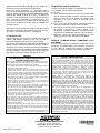
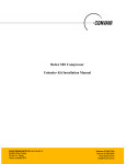
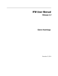
Combined protective patterns are shown in Figure 1 for a
nominal mounting height of 7.5 ft (2.3m). The microwave
detection pattern shown in Figure 1 represents coverage in
open space. In practical applications, when the detector is
bounded by ceiling, floor, and walls, reflections can occur.
Coverage Pattern Not Available
SELECTING A MOUNTING LOCATION
The detector responds to changes in energy which occur when
an intruder moves into the combined protection pattern. Best
coverage will be obtained if the mounting site is selected so
that the likely direction of intruder motion is generally across
the pattern and angles slightly toward the detector.
Figure 1. COVERAGE PATTERN
www.PDF-Zoo.com
INSTALLATION HINTS
Special Instructions
for Installations Containing Pets
The detector is remarkably resistant to false alarm hazards,
but the following recommendation should be observed.
• Never install the detector in an environment that causes
an alarm condition in one technology. Good installations
start with both LEDs OFF when in the Accu-Trak test
mode and there is no target motion.
• Do not mount on an unstable surface. Locate the unit on a
sturdy inside wall whenever possible. Avoid sources of
vibration such as loose fitting doors and walls that shake
when heavy traffic exists.
• Do not install on or close to metal structures such as metal
door frames, shelves, etc.
• Do not include space heaters in the protective pattern
whenever possible, to avoid rapid temperature changes
and vibrations from fans.
• ALL microwave transmission penetrates most building
materials (except metal, which reflects transmission).
Moving objects outside of the protected area may be
detected unless the microwave sensitivity control is kept at
as low a setting as possible, to minimize penetration.
• Make sure the detection area does not have obstructions
(curtains, screens, large pieces of furniture, plants, etc.)
which may block the PIR portion of the coverage pattern.
MOUNTING
Mount the unit to a firm vertical surface. The wall wiring hole
should be no more than 5/16" (8mm) diameter.
1. Remove the front cover by twisting a screwdriver blade in
the groove between cover and base at the bottom edge of
the case and then lifting the cover off.
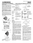
2. Remove the circuit board from the base. Loosen the
vertical adjustment screw, slide the circuit board up and
spread PCB holding tabs as shown in Figure 3.
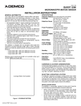
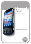
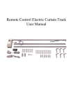
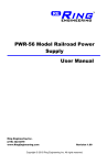
3. Breakout desired mounting & entry holes. Refer to Figure
2. Knockout holes “A” in the base are for normal surface
mounting on a wall. Knockout holes “B” are for corner
mounting. Also break out the wire entry hole at this time
marked X in Figure 2.
4. Feed wiring (unpowered) coming from the wall through the
wire access hole near the top of the detector base. Use the
wiring channel on the back to assist with routing.
5. Mount the base & reinstall the PC board.
6. Vertically align PCB before tightening screw.
7. Refer to WIRING CONNECTIONS section before
replacing the cover.
The QUEST 2235 will provide reasonable protection from
nuisance alarms caused by the following sources:
•
•
•
•
•
A dog up to 100 pounds.
Two dogs, up to 60 pounds each.
Up to 10 cats.
Multiple small rodents, such as rats.
Random flying birds.
To take full advantage of the QUEST 2235’s next generation
performance for pet immunity, the following guidelines should
be followed:
• Mount the center of the detector 7.5 feet high & adjust the
PCB to POSITION TWO.
• Set the sensor sensitivity for standard (STD).
• Mount where animals cannot come within six feet of the
detector by climbing on furniture, boxes, or other objects.
• Do not aim the detector at stairways that can be climbed
by an animal.
• Adjust the microwave range for the minimum acceptable
coverage for the room in which the detector is installed.
Never install with the microwave range exceeding 35 feet.
WIRING CONNECTIONS
Bring all wires through the wire access slot at the top of the
detector base near the terminal block and connect to the screw
terminal. See Figure 3 for wiring details. Seal any openings in
the base with foam or RTV (not supplied) to prevent drafts and
insects from entering the unit. Apply power only after all
connections have been made and are inspected.
TERM
1
2
3
4
5
6,7
8
FUNCTION
+12 Input Supply. Power must be provided from a
12VDC filtered source with 25ma capability and at
least 4 hours of standby battery capacity.
(-) Input Supply (ground).
Relay Contact, N.C. (Open on Alarm)
Relay Common Contact
SPARE
Tamper Switch, N.C. (Open on Tamper)
Trouble Output. Upon supervision failure, this open
collector output will go low (requires 1000-ohm pull-up
resistor.) Use shielded wire for UL installations.
REMOTE LED DISABLE
A separate terminal pin is provided on the PCB that can be
used to remotely control the LED. (See Figure 3.) If a 7-16VDC
signal is applied to the terminal, all LED functions will be
disabled, including alarm, Accu-Trak test mode, and
supervision failures. To remotely enable the LED by removing
the 7-16VDC signal, DIP Switch #3 must be set to OFF (LED
enable).
Figure 2. CASE BACK
www.PDF-Zoo.com
ADJUSTMENTS AND SELECTIONS
LED ENABLE/DISABLE OPTION
MICROWAVE SENSITIVITY CONTROL:
Turn the potentiometer clockwise to increase sensitivity.
DIP SWITCH SETTINGS:
#1: ON Accu-Trak test mode (relay
remains open when selected)
OFF Normal operation
#2: ON Intermediate signal processing.
OFF Standard signal processing
(recommended for installations with pets)
#3: ON LED disable
OFF LED enable
To enable the LED, set the DIP Switch #3 OFF. To disable the
LED, set DIP Switch #3 ON. Use a small pointed tool to move
the switch handle.
LED INDICATIONS
Accu-Trak Test Mode: Ademco’s unique Accu-Trak test
feature is easy to use. It can be used to provide both pattern
coverage and as an environmental check for potential false
alarms. Simply set DIP Switch #1 to ON. Both microwave and
PIR information is viewable simultaneously on the two LEDs,
providing crisp, immediate feedback (see below).
MODE
Power Up
Alarm
Accu-Trak
Test Mode
Supervision
Failure
LED INDICATIONS
Red & Green LEDs ON for ~50 secs.
Red LED ON.
Green LED FLASHES for microwave
Red LED flashes for PIR
Red LED flashes for PIR failure;
Green LED flashes for microwave failure.
Note: When Accu-Trak test mode is selected, alarm relay is
constantly held open to prevent leaving the detector in the test
mode.
SIGNAL PROCESSING OPTION
For Standard Signal Processing, set DIP Switch #2 OFF. For
Intermediate Signal Processing, set DIP Switch #2 ON. Use a
small pointed tool to move the switch handle.
Standard Signal Processing: This is the recommended
setting for maximum false alarm immunity. It tolerates
environmental extremes on this setting.
Note: Standard Signal Processing is recommended for
installations with pets.
Intermediate Signal Processing: This is the recommended
setting for any location where an intruder is expected to cover
only a small portion of the protected area. It tolerates normal
environments on this setting.
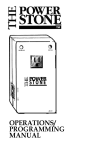
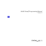
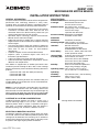
1 12VDC(+) INPUT SUPPLY
2 12VDC(-) INPUT SUPPLY
3 RELAY CONTACT, N.C.
4 RELAY COMMON CONTACT
5 SPARE
6 TAMPER
7 TAMPER
8 TROUBLE OUTPUT
FOR SUPERVISION
(Use shielded wire
for UL installations)
TERMINAL STRIP
CIRCUIT BOARD
HOLDING TAB
(BEND BACK TO
REMOVE BOARD)
REMOTE LED PIN
MICROWAVE
DETECTOR
(DRO)
MICROWAVE SENSITIVITY
CONTROL
TURN CLOCKWISE TO
INCREASE SENSITIVITY
TEST PROCEDURES
On power-up, testing must not begin until the LED
extinguishes after first applying power to signify warm-up is
complete, about 50 seconds. If the LED begins to flash at a
constant rate, refer to the section on SUPERVISION.
Note: During this warm-up period the relay will be held
CLOSED.
LED
ACCU-TRAK LED INDICATIONS
COLOR
WALK TEST
ENVIRON TEST
PIR
RED
LED flashes when LED flashes when
entering or exiting
potential false
zone.
alarm source is
detected, such as
fans or heating duct.
Microwave GREEN LED goes ON upon LED is ON when
entering microwave potential false
coverage pattern. alarm source is
detected, such as
a fan or balloon.
Note:
1) The alarm relay remains continuously open when test
mode is selected to prevent leaving the detector in test
mode.
2) Because of the advanced C3 signal processing, this test
mode should only be used to verify limits of the coverage
pattern of each technology and to check for potential
environmental disturbances.
Testing in Normal Operating Mode: After testing with
the unique Walk-Test mode, the detector should be tested in
the Normal Operating Mode with the following steps:
1. Remove the front cover and ensure that DIP Switch #1 is
set to OFF for Normal Operating Mode.
2. Set DIP Switch #2 to the Pulse Processing Option that will
be used for this installation.
3. Enable the LED by setting DIP Switch #3 OFF.
4. Replace the front cover and walk through the protective
zones, observing that the detector’s red LED lights
whenever motion is detected. If necessary, re-adjust the
microwave sensitivity to the minimum level required for
satisfactory detection and repeat the walk test.
Note: The relay will open when the LED lights.
5. After walk-testing is complete, the LED may be disabled,
if desired (DIP Switch #3 ON).
PCB SCREW
0
LOOKDOWN LENS
8
VERTICAL
ADJUSTMENT
SCALE
TAMPER SWITCH
GREEN LIGHT
PIR DETECTOR
RED LIGHT
Figure 3. INTERIOR OF DETECTOR
www.PDF-Zoo.com
SUPERVISION
This motion sensor is equipped with advanced supervision of both
the PIR and microwave channels. If a microwave channel failure
occurs, the sensor will continue to operate as a dual element PIR
sensor in Standard Signal Processing mode regardless of the
processing option chosen. Even though some operation is
maintained, the unit should be replaced as soon as possible. If a
PIR failure occurs, the unit becomes non-operational.
Supervision failure indications:. If a supervision failure
occurs, it will be indicated by the appropriate LED flashing 2
times per second, regardless of the LED enable/disable option
chosen by DIP Switch. If a PIR failure occurs, the RED LED
will flash; if a microwave failure occurs, the GREEN LED will
flash. If the unit has defaulted to PIR-only operation as a
result of a microwave failure, the RED LED will light when an
alarm occurs if enable by DIP Switch while the GREEN LED
continues to flash.
Upon supervision failure, the open collector TROUBLE output
on the terminal block will also go low (requires 1000-ohm pullup resistor). Use shielded wire for UL installations.
TO THE INSTALLER
Regular maintenance and inspection (at least annually) by the
installer and frequent testing by the user are vital to
continuous satisfactory operation of any alarm system.
The installer should assume the responsibility of developing and
offering a regular maintenance program to the user, as well as
acquainting the user with the proper operation and limitations
of the alarm system and its component parts. Recommendations
must be included for a specific program of frequent testing (at
least weekly) to insure the system’s operation at all times.
WARNING
THE LIMITATIONS OF YOUR MICROWAVE/PASSlVE
INFRARED MOTION DETECTOR
While the Intrusion Detector is a highly reliable intrusion detection device, it does
not offer guaranteed protection against burglary. Any Intrusion Detection device is
subject to compromise or failure to warn for a variety of reasons:
• These Motion Detectors can only detect intrusion within the designed ranges as
diagrammed in this installation manual.
• The passive infrared motion sensor in this Motion Dectector do not provide
volumetric area protection. It does create multiple beams of protection, and
intrusion can only be detected in unobstructed areas covered by those beams.
• Passive Infrared Detectors cannot detect motion or intrusion that takes place behind
walls, ceilings, floors, closed doors, glass partitions, glass doors, or windows.
• Metal objects (or other reflectors, such as foil faced insulation or water in bottles)
can alter the microwave sensors protection pattern.
• Mechanical tampering, masking, painting or spraying of any material on the
mirrors, windows or any part of the optical system can reduce the detection
ability of the Passive Infrared Motion Detector.
• Passive Infrared Detectors sense changes in temperature; however, as the
ambient temperature of the protected area approaches the temperature range of
90° to 105°F (32° to 40°C), the detection performance can decrease.
• This Passive Infrared Detector will not operate without appropriate DC power connected
to it or if the DC power is improperly connected (i.e. reversed polarity connections).
• Passive Infrared Detectors, like other electrical devices, are subject to
component failure. Even though they are designed to last as long as 10 years,
the electronic components could fail at any time.
We have cited some of the most common reasons that a Passive Infrared Motion
Detector can fail to catch intrusion. However, this does not imply that these are the only
reasons and therefore, it is recommended that weekly testing of this type of unit, in
conjunction with weekly testing of the entire alarm system, be performed to ensure that
the detectors are working properly.
Installing an alarm system may make the owner eligible for a lower insurance rate,
but an alarm system is not a substitute for insurance. Homeowners, property owners
and renters should continue to act prudently in protecting themselves and continue
to insure their lives and property.
We continue to develop new and improved protection devices. Users of alarm systems
owe it to themselves and their loved ones to learn about these developments.
MAINTAINING PROPER OPERATION
In order to maintain the detector in proper working condition,
it is important that the following be observed
by the user:
1. Power should be provided at all times. Loss of power to the
unit will result in the alarm contacts reverting to an alarm
state. The unit’s DC source should have standby power
available for at least 4 hours of operation during
emergencies.
2. Units should never be re-aimed or relocated without the
advice or assistance of the alarm service company.
3. The physical surroundings of the protected area should not
be changed. If furniture or stock is moved, or air
conditioning or additional heating is installed, the system
may have to be readjusted by the alarm service company.
4. Walk-tests should be conducted frequently (at least
weekly) to confirm proper coverage by each detector.
FEDERAL COMMUNICATIONS COMMISSION (FCC)
STATEMENT
The user shall not make any changes or modifications to the
equipment unless authorized by the Installation Instructions
or User’s Manual. Unauthorized changes or modifications
could void the user’s authority to operate the equipment.
ADEMCO LIMITED WARRANTY
Alarm Device Manufacturing Company, a Division of Pittway Corporation, and its
divisions, subsidiaries and affiliates ("Seller"), 165 Eileen Way, Syosset, New York
11791, warrants this detector to be in conformance with its own plans and
specifications and to be free from defects in materials and workmanship under
normal use and service for 72 months from the date stamp control on the product.
Seller's obligation shall be limited to replacing, at its option, free of charge for
materials or labor, a detector which is proved not in compliance with Seller's
specifications or proves defective in materials or workmanship under normal use
and service. Seller shall have no obligation under this Limited Warranty or otherwise if the detector is altered or improperly repaired or serviced by anyone other
than Ademco factory service. In case of defect, return the detector to ADI or an
authorized distributor for an immediate replacement.
THERE ARE NO WARRANTIES, EXPRESS OR IMPLIED, OF
MERCHANTABILITY, OR FITNESS FOR A PARTICULAR PURPOSE OR
OTHERWISE, WHICH EXTEND BEYOND THE DESCRIPTION ON THE FACE
HEREOF. IN NO CASE SHALL SELLER BE LIABLE TO ANYONE FOR ANY
CONSEQUENTIAL OR INCIDENTAL DAMAGES FOR BREACH OF THIS OR ANY
OTHER WARRANTY, EXPRESS OR IMPLIED, OR UPON ANY OTHER BASIS OF
LIABILITY WHATSOEVER, EVEN IF THE LOSS OR DAMAGE IS CAUSED BY
THE SELLER'S OWN NEGLIGENCE OR FAULT.
Seller does not represent that its detector may not be compromised or circumvented; that the detector will prevent any personal injury or property loss by
burglary, robbery, fire or otherwise; or that the detector will in all cases provide
adequate warning or protection. Buyer understands that a properly installed and
maintained alarm may only reduce the risk of a burglary, robbery, fire or other events
occurring without providing an alarm, but it is not insurance or a guarantee that such
will not occur or that there will be no personal injury or property loss as a result.
CONSEQUENTLY, SELLER SHALL HAVE NO LIABILITY FOR ANY PERSONAL
INJURY, PROPERTY DAMAGE OR OTHER LOSS BASED ON A CLAIM THE
DETECTOR FAILED TO GIVE WARNING. HOWEVER, IF SELLER IS HELD LIABLE, WHETHER DIRECTLY OR INDIRECTLY, FOR ANY LOSS OR DAMAGE
ARISING UNDER THIS LIMITED WARRANTY OR OTHERWISE, REGARDLESS
OF CAUSE OR ORIGIN, SELLER'S MAXIMUM LIABILITY SHALL NOT IN ANY
CASE EXCEED THE PURCHASE PRICE OF THE DETECTOR, WHICH SHALL
BE THE COMPLETE AND EXCLUSIVE REMEDY AGAINST SELLER. This
warranty replaces any previous warranties and is the only warranty made by Seller
on this detector. No increase or alteration, written or verbal, of the obligations of this
Limited Warranty is authorized.
ALARM DEVICE MANUFACTURING COMPANY
A DIVISION OF PITTWAY CORPORATION
165 Eileen Way, Syosset, New York 11791
Copyright© 1998 PITTWAY CORORATION
www.PDF-Zoo.com
ÊN8656N
N8656 6/98