1
IPT
Current-to-Pressure
(I/P) Transmitter
2
IPT
Current-to-Pressure
2 (I/P)
Transmitter
May 2008
170-730-00B
All product names are registered trademarks of their respective companies.
Table of Contents
Introduction ........................................................................................................ 1
The IPT 2 .............................................................................................................. 1
Specifications .................................................................................................... 1
Ordering Information ......................................................................................... 2
Instrument Air and Filtration Information ......................................................... 3
Application Information ..................................................................................... 4
Recommendations .............................................................................................................. 4
Calibration .......................................................................................................... 5
Adjustments ........................................................................................................................ 5
Calibration Equipment ......................................................................................................... 5
Test Jacks ........................................................................................................................... 6
Calibration Setup ................................................................................................................. 6
Calibration Procedure ......................................................................................................... 6
Installation .......................................................................................................... 7
Mounting ............................................................................................................................. 7
Electrical Connections ......................................................................................................... 8
Pneumatic Connections ...................................................................................................... 8
Operation ............................................................................................................ 9
Maintenance ....................................................................................................... 9
Troubleshooting ................................................................................................. 9
CE Declaration of Conformity ......................................................................... 10
IPT 2
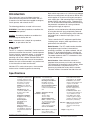
Introduction
This is the users’ manual for Moore Industries’
advanced current-to-pressure transmitter, the IPT2.
It contains all of the information needed to configure,
install, operate, and maintain the IPT2.
The following guidelines are used in this manual:
block, which snaps onto a rail. Units that are ordered
without a mounting block will clip onto an RIR or SIR,
which supplies air to each unit using only one pneumatic supply pipe. Both mounting blocks and supply
headers contain self-sealing valves. Therefore, the
IPT2 can be removed and replaced without disturbing
the pneumatic connections or causing accidental
venting of the supply or output air.
Caution - Hazardous procedure or condition that
could damage or destroy the unit.
Operation can be monitored or calibration performed
by using the electrical input and optional pneumatic
output test jacks. A red LED display, which indicates
the presence of an electrical input signal, is also
standard.
Note - Information that is helpful for a procedure,
condition, or operation of the unit.
Table 1 contains the IPT2 equipment specifications,
including inputs, outputs, power requirements, and
performance characteristics.
WARNING - Hazardous procedure or condition that
could injure the operator.
2
The IPT
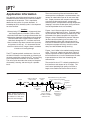
The IPT2 is a compact, closed-loop, 2-wire current-topressure transmitter that converts a standard process
current signal to a pneumatic output. In its compact
aluminum housing, the IPT2 snaps onto standard
mounting rails or onto a Moore Industries RIR or SIR.
Because of the low dynamic mass of the transducer
element, the unit can be mounted in any position and
is also insensitive to shock and vibration.
Individual IPT2s consist of two parts: the transmitter
section and an interlocking pneumatic mounting
Model Number. The IPT2 model number describes
the equipment type, functional characteristics,
operating parameters, any options ordered, and unit
housing. If all other documentation is missing, this
number is used to identify equipment characteristics.
The model number for the IPT2 is located on a label
on the side of the unit.
Serial Number. Moore Industries maintains a
complete history on every unit it sells and services.
This information is keyed to the serial number. When
service information is required on the IPT2, it is
necessary to provide the factory with this number.
The serial number is located on the side of the unit.
Specifications
Performance Accuracy: <±0.25% of span
including the combined effect
of linearity, hysteresis, and
repeatability (between 0.5 and
3psi output, error will not
exceed ±1.0% of span)
Stability: Not to degrade
from stated accuracy for six
months
Step Response: <0.2
seconds into 100 M.L. load
(6 cubic inches) at 90%
output span
Supply Pressure Effect:
Negligible from 20-40psig,
steady pressure
Air Consumption:
0.08 SCFM, typical
(0.18 kg/hr)
Air Capacity:
Minimum 2.0 SCFM
Air Supply: Instrument air
only, 20-40psig. (Must be 5
psig greater than maximum
output)
Performance Voltage Drop:
(Continued) 7.5V, maximum (5V
maximum without LED)
Mounting Position Effect:
Negligible, unit can be
mounted in any position
Shock and Vibration Effect:
0.25%/G or better over
5-15Hz; meets SAMA PMC
31.3
Ambient Operating & Storage
Conditions Range:
-40°C to +80°C
-40°F to +176°F
Ambient Temperature
Effect: <±0.025% of span/
°C, max from 0°C to 50°C;
<±0.1% of span/°C, max.
RFI/EMI Effect:
<±0.1% of span change at
50V/m @ 20-1000MHz.
Adjustments Zero & Span: Screw adjusts
zero or span by ±10%
minimum, non-interactive
Connections Electrical:
Removable front-mounted
terminal blocks, 22-14 AWG
Pneumatic: 1/8-inch NPT
female for both supply air and
output air on units with
optional mounting block.
Pneumatic Test Jacks:
Monitors output pressure
during calibration
Current Test Jacks: Input
current test jacks (labeled +T,
–T) for calibration; accepts
2mm (0.08 in) dia x 13mm
(.50 in) long phone tip plugs
(handles should be less than
8mm (0.32 in) in diameter)
Indicators LED: Red light-emitting diode
indicates presence and
intensity of electrical input
signal.
Weight
438g (15.6 oz)
Specifications subject to change without notice.
The Interface Solution Experts
1
IPT 2
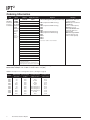
Ordering Information
Unit
Input
IPT2
DIN-Style
Current-toPressure
Transmitter
4-20MA
4-12MA
12-20MA
into 375Ω
maximum
(250Ω
maximum
for units
without
LED)
Custom
ranges also
available.
Output*
Supply Pressure**
Options
Housing
25PSI
25PSI
20PSI
25PSI
25PSI
35PSI
35PSI
1.4BAR
140KPA
1.4KGCM2
.14MPA
**Access Designation (Required Selection):
DIN Aluminum, DIN-style
housing assembly.
WTI Rain-proof as defined
by NEMA 3R
(–FA7 or –FA8 required)
WTIP Rain-proof as
defined by NEMA 3R with
plate and u-bolts for 2”
pipe mounting
NWP Water tight NEMA 4
enclosure (Europe only,
–FA1 or –FA3 required)
0-20PSIG
1-17PSIG
3-15PSIG
3-16.6PSIG
3-18PSIG
3-27PSIG
6-30PSIG
.2-1BAR
20-100KPA
.2-1KGCM2
.02-.10MPA
Reverse Output:
20-0PSIG
17-1PSIG
15-3PSIG
16.6-3PSIG
18-3PSIG
27-3PSIG
30-6PSIG
1-.2BAR
100-20KPA
1-.2KGCM2
.10-.02MPA
25PSI
25PSI
20PSI
25PSI
25PSI
35PSI
35PSI
1.4BAR
140KPA
1.4KGCM2
.14MPA
–FA1 (Required for NWP Housing)
–FA2
–FA3 (Required for NWP Housing)
–FA4
–FA5
–FA6
–FA7 (Required for WTI Housing)
–FA8 (Required for WTI Housing)
–FA9
–FA10
–FA11
–FA12
**See Table 1 below for more information
*The unit’s output must match the supply
pressure to its right.
**Supply Pressure must be at least 5psi (0.3
Bar) higher than output pressure. (40psi max)
When ordering, specify: Unit / Input / Output / Supply Pressure / Options [Housing]
Model number example: IPT2 / 4-20MA / 3-15PSIG / 20PSI / –FA1 [DIN]
Table 1. Description of access designation options. (See Figure 4, page 8)
2
Option
LED & Current
Test Jacks
Electrical Input
Location
Pneumatic Output
Supply Location
Pneumatic Test
Jack Location
–FA1
–FA2
–FA3
–FA4
–FA5
–FA6
–FA7
–FA8
–FA9
–FA10
–FA11
–FA12
Yes
Yes
Yes
Yes
None
None
Yes
Yes
None
None
None
None
Front
Front
Front
Front
Front
Front
Front
Front
Front
Front
Front
Front
Bottom
Rear
Bottom
Rear
Bottom
Rear
No mounting block
No mounting block
No mounting block
No mounting block
Bottom
Rear
None
None
Front
Front
None
None
None
Front
None
Front
Front
Front
The Interface Solution Experts
IPT 2
Instrument Air and
Filtration Information
Note:
For optimum performance, the selection and
use of a good quality air filtration system is
essential. Most users find that it is much less
expensive and troublesome to design a system
that includes good air filtration than deal with
downtime and repairs later.
A clean, dry air supply is important to assure the
maximum service life of an IPT2. Good air quality
involves removing solids, oil and water from the air
after compression. The cleaner the air, the longer the
time before servicing is needed.
Oversizing elements avoids performance abberations
and reduces maintenance time. Redundancy should
be used where possible to avoid shutdown during
maintenance.
Solids: Random solid dirt, such as pipe scale and
rust, is rarely a problem in compressed air instrument
systems. A good filter removes these solids. However, if there is a desiccant dryer in the line, a highefficiency sub-micron filter is recommended to remove
the highly abrasive sub-micron particles produced by
the dryer.
Liquid Oil: Liquid oil is the most common problem in
compressed air instrument systems. A coalescing
filter removes sub-micron liquid droplets from the air,
and is usually supplied with an automatic drain.
A coalescing filter works by trapping oil and water
droplets in a bed of microfibers. The droplets run
together at fiber cross-over points, form large liquid
drops, and are forced by air flow to a drain. A filter
system consisting of a general purpose first-stage filter
(about 5 micron) and a high-efficiency coalescing final
filter is recommended to obtain contaminant-free air.
The exact location of the first-stage filter is not important; it can be located just ahead of each final filter, or
a single first-stage filter can be located on a main line
to protect a number of final filters on branch lines.
Each final filter (coalescing) should be located just
ahead of each pressure regulator. In a new plant
installation, an oilless compressor may be used to
eliminate this problem.
Water: The amount of water in an air system
depends on temperature, pressure and the relative
humidity of the air.
Sufficient water must be removed to lower the dew
point of the air to a temperature below ambient. The
dew point (at line pressure) is expressed as the
temperature at which any moisture in the system
begins to condense.
Water may be removed using a number of techniques,
including coalescing filters, refrigeration dryers and
desiccant dryers. In addition, a variety of combinations and modular systems may be used for special
circumstances.
Care must be taken in the selection and location of
the filter, because cooling downstream of the filter can
cause more condensation of water. A coalescing filter
should be installed immediately upstream of the
pressure regulator. This type of filter removes most of
the water before the air enters the regulator.
For systems subjected to freezing temperatures, the
portion of the system that runs outdoors should have a
dryer installed. The dryer reduces the dew point
below the lowest expected outdoor temperature. A
desiccant dryer is used with a coalescing filter upstream to keep the desiccant dryer from being damaged by oil or overloaded with excessive condensed
water. Another high-efficiency coalescing filter is
recommended downstream of the dryer, to remove the
desiccant particles.
ISA Specifications: The Instrument Society of
America standard ISA-S73, 1975 (ANSI MC11.1-1975)
covers the air quality requirements for instrument
grade air for use in pneumatic installations.
The dew point in outdoor installations must be at least
7.8°C (18°F) below the minimum local ambient temperature. For indoor installations, the dew point must
be at least 7.8°C (18°F) below the minimum interior
temperature or 2°C (35°F), whichever is greater.
Although the ISA standard calls for a 35°F dew point,
this is often unnecessary indoors, and may be unsatisfactory outdoors under freezing conditions.
Filters that exceed the ISA specification provide very
inexpensive protection. Although the ISA specification
calls for particle size not to exceed 3 microns and oil
content not to exceed 1ppm, most filter manufacturers
supply a line of coalescing filters that remove particles
down to sub-micron sizes (often 0.01 micron) while
also removing oil to below ISA 1ppm specification
(often to 0.01ppm).
The Interface Solution Experts
3
IPT 2
Application Information
Any approach to providing good instrument air quality
should evaluate the worst case air flow and ambient
temperature of the location. This is required to
determine sizing of the air system elements. A
knowledge of yearly humidity cycles is also important
for this evaluation.
Caution:
Before placing IPT 2s in service, all pneumatic lines
and mounting blocks or headers (SIRs or RIRs)
should be "blown down" to purge contamination and
condensation deposited during piping and installation.
Also blow down lines to loads, since all output air
vents back through the IPT2, and there are never
filters installed to trap these contaminants (normally
only present at start-up). It is recommend this be
done for at least an hour, longer if there is evidence
of water or oil coming through.
The IPT2 requires periodic maintenance. Service in
the field is limited to visual inspection and cleaning of
the input nozzle filter screen on the IPT2 and servicing
of the compressed instrument air filtration system.
The unit may be returned to the factory for complete
disassembly, cleaning, and servicing on a periodic
basis.
The use of coalescing filters with retention of 0.01
micron particles and droplets is recommended; they
remove all undesirable traces of oil and water droplets. Proper placement with respect to the regulator
may eliminate the need for dryers, except when
coalescing filters are exposed to freezing temperature
(keeping in mind that the dew point of the purified air
must be kept below worst case ambient).
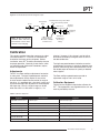
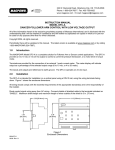
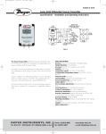
Figures 1 and 2 illustrate typical non-redundant
systems with multiple branch lines. They both work in
any environment above freezing and differ only in the
placement of the general purpose first-stage filter.
Gauges, valves, and differential pressure indicators
(for filter service monitoring) are not shown. It is
recommended that filters with integral service life
indicators or differential pressure indicators be used
to help ensure proper servicing, as well as redundancy to avoid shutdown during servicing.
Figures 1 and 2 differ in the method used to remove
water. The use of a desiccant type dryer (Figure 2)
requires upstream filtration to prevent oil contamination of the desiccant, as well as downstream filtration,
to prevent desiccant fines from introducing new
contamination.
The service life of an IPT2 is directly proportional to
the cleanliness and dryness of its air supply. The
small cost of providing high-quality air ensures a
longer, more trouble-free service life for the unit.
Figure 1. Non-Redundant System with Desiccant Dryer
Cooler
D
Receiver
Note: All filters should have
automatic drains and service
life indicators to show when
elements need changing.
4
The Interface Solution Experts
Dessicant
Dryer
Extend Branch Line(s) Above Main
Line to Avoid Passing Liquids
Pressure
Regulator
Main Line to
Other Branches
High-Efficiency
Coalescing
Filter
5-Micron General
Purpose Filter(s),
One Main or Multiple
on Branch Lines
Purified Air
For IPT2's
{
5-Micron General
Purpose Filter
Keep Short
0.01-Micron
High Efficiency
Coalescing
Filter(s)
IPT 2
Figure 2. Non-Redundant System with Refrigeration Dryer
Refrigeration
Dryer
Cooler
Extend Branch Line(s) Above Main
Line to Avoid Passing Liquids
Main Line to
Other Branches
D
Receiver
Pressure
Regulator
{
Purified Air
For IPT2's
Keep Short
5-Micron General
Purpose Filter(s),
One Main or Multiple
on Branch Lines
Note: All filters should have
automatic drains and service
life indicators to show when
elements need changing.
0.01-Micron
High Efficiency
Coalescing
Filter(s)
Calibration
This section provides information necessary to adjust
and calibrate the IPT2. Each unit is calibrated and
checked at the factory prior to shipment. Before
installation, every IPT2 should be checked by the user
for proper operation. Generally, these checks, which
are specified under Calibration Procedures, require
little or no adjustment.
Adjustments
The IPT2 has Zero and Span adjustments located on
its front panel. The type of potentiometer used with
these adjustments usually require 15 turns of the
shaft to move the wiper from one end of its range to
the other. It is equipped with a slip clutch at each end
to prevent damage if the adjustment is turned beyond
the wiper stop. Usually a slight change can be felt
when the clutch is at the end of a range (i.e., it is
slipping). However, if this change is not felt, either
end can be reached by turning the shaft 15 turns in
the desired direction.
Turning these potentiometers clockwise causes the
related output to increase in quantity or become more
positive; while turning them counterclockwise causes
the related output to decrease in quantity or become
more negative.
The Zero and Span potentiometers provide an
adjustment range of ±10% of full scale.
Calibration Equipment
Table 2 lists the equipment required to calibrate the
IPT2. This equipment is not supplied with the unit and
must be provided by the user.
Table 2. Calibration Equipment
Equipment
Characteristics
Purposes
Adjustable current source
0-50mA output
Simulate input signal
DC milliammeter
Accurate to ±0.05%
Measure input signal
Instrument air supply
Filtered
Air supply
Air pressure gauge
Accurate to ±2%
Measure air supply pressure
Air pressure gauge
Accurate to ±0.1%
Measure output pressure
Phone tip probes (2)
Must have 2mm (0.8 in) diameter tips, .5 inch long
Easy access to input signal (optional)
Pneumatic test coupler
MII P/N 163-202-00
For IPT2s with optional test jacks
Easy monitoring of output pressure (optional)
Pneumatic load
Volume of 7.5 cubic inches (approx. 120 milliliters)
Provide standard load for testing (per IEC spec. #770)
The Interface Solution Experts
5
IPT 2
Test Jacks
Calibration Procedure
2
The +T and –T test jacks on the front of the IPT are
provided as a convenient means of monitoring the
process loop to which the product is connected
without disconnecting the unit or interrupting the loop.
A milliammeter connected to the +T and –T test jacks
will provide a reading in the range of the unit's output
rating (Figure 5). The model number of the IPT2
shows its output range.
Caution:
The maximum resistance the milliammeter can
introduce into the test jack circuit and still provide
accurate readings is 10Ω.
If the milliammeter readings are not as anticipated,
verify that the milliammeter is rated for no more than
10Ω impedance. If the unit is suspect of improper
operation, remove it from the test jacks and calibrate
the IPT2.
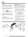
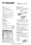
Calibration Setup
Figure 3 is an illustration of a typical calibration setup,
including optional equipment. To check or calibrate
the IPT2, connect the unit as shown in this illustration.
There are two options shown in Figure 3 for monitoring the output of the IPT2. The input current may be
measured by placing a milliammeter in series with the
input terminals as indicated by M1 or connected
across the electrical test jacks by a milliameter of less
than 10Ω impedance (+T and -T) as indicated by M2.
1. For zero adjustment, connect an adjustable
current source to the electrical input terminal
block. Set the current input signal to zero percent
(e.g., 4mA for a 3-15psig unit with a 4-20mA
output, 20mA for a 15-3psig unit with a 4-20mA
output).
Note:
Observe that the red LED indicator on the
front panel is illuminated at zero input
current and glows somewhat brighter with
increasing current.
2. Using an air pressure gauge to measure the input
air supply pressure, connect a filtered air supply
to the pneumatic supply port located on the
bottom or rear of the unit.
3. If the unit is supplied with the optional frontaccess pneumatic-output test jack, insert the
pneumatic coupler into the receptacle. This
avoids having to disturb any operating connections or fittings.
Figure 3. Calibration Setup
+
M1
le
stab
Adju rent –
Cur ce
r
Sou
Pressure
Out
IPT 2
CU
TR RR
AN EN
SM T/P
IT RE
TE SS
R
UR
E
+IN
SP
AN
+I
N
–IN
ZE
RO
–IN
+T
–T
Pressure
Gauge
±0.1%
d
Loa
e
(Se )
2
e
l
Tab
Pressure
In
+T
–T
M2
6
The Interface Solution Experts
Pressure
Gauge
±2%
ed
ulat
Reg ment
ru
Inst upply
S
r
i
A
IPT 2
Caution:
Coupler must be kept lubricated to prevent
damage to O-rings in test jacks. Teflon lubricant is recommended. If grease is used, keep
out of air passage.
If the unit is not supplied with the output test jacks,
use an air pressure gauge to measure the output air
supply pressure (e.g., read 3psig for a 3-15psig unit or
15psig for a 15-3psig unit).
4. Any deviation in the output pressure (e.g., 3 psig
for a 3-15 psig unit or 15 psig for a 15-3 psig unit),
can be corrected by using the Zero potentiomenter
in a range of ±10%.
5. Any deviation in the output pressure (e.g., 15 psig
for a 3-15 psig unit or 3 psig for a 15-3 psig unit),
can be corrected by the Span potentiometer over
the range of ±10%.
6. Repeat steps 1 through 5 (as applicable) until no
further adjustments are required.
Installation
Installation of the IPT2 is divided into three phases:
mounting, electrical connections, and pneumatic
connections. In most cases, it is easier to mount the
IPT2 before completing the electrical and pneumatic
connections.
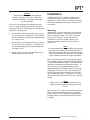
Mounting
Individual IPT2s consist of two parts: the transmitter
and the mounting block. Units without a mounting
block snap onto a header. IPT2s with a mounting
block are rail mounted. Ensure that the unit is
mounted in an area free of dust, moisture, and
corrosive elements. See Figure 4 for mounting
dimensions.
Note:
It is recommended that mounting blocks and headers
be purged of any debris prior to mounting the IPT 2.
Insert a small diameter, blunt tip probe into the fitting
and unseat the ball-check valves for a few minutes
with the filtered instrument air supply in operation.
Rack- or surface-mounted IPT2s should be ordered
with a Moore Industries' rack-mounted header (RIR) or
a surface-mounted header (SIR). This eliminates the
need for an interlocking mounting block and rail. 5,
10 or 15 units can be snapped onto one header,
allowing multiple units to receive supply air from one
supply pipe. To mount an IPT2 onto a header, push
the unit into place until the retaining lever snaps up
flush beneath the handle. To remove an IPT2, press
down on the retaining lever and lift the unit out by the
handle.
Note:
Check valves in the headers prevent the loss of
supply or output air during mounting or removal
of IPT 2s.
Rail-mounted IPT2s must use a pneumatic mounting
block. Pneumatic mounting blocks are 1.39 inches
wide. Using a 0.17 inch wide gauge between blocks
provides uniform spacing while occupying minimum
rail length.
The Interface Solution Experts
7
IPT 2
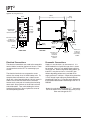
Figure 4. Mounting Dimensions
96mm
(3.77 in)
39mm
(1.55 in)
9mm
(.37 in)
IPT 2
CURRENT/PRESSURE
TRANSMITTER
Red LED "ON"
When Input
Current is Present
+IN
–IN
SPAN
Span Adj.
ZERO
Zero Adj.
85mm
(3.35 in)
Pneumatic
Test Jack
+T
–T
Electrical Test Jack
(Calib.) For
2 mm (0.8 in) Dia.
Phone Tip Plug
10mm
(0.38 in)
10mm
(.40 in)
20mm
(0.78 in)
FRONT VIEW
Mounting
Block
8mm
(0.32 in)
124mm
(4.90 in)
SIDE VIEW
Bottom Access
Location for
Pneumatic
Connections,
1/8 NPT
12mm
(.45 in)
Rear Access
Location for
Pneumatic
Connections,
1/8 NPT
Electrical Connections
Pneumatic Connections
The electrical connections are made to the removable
terminal blocks located on the front of the unit. There
are two terminals on the IPT2 for connecting input
current.
Supply air must be clean, dry instrument air. It is
recommended that all particles larger than 1 micron
be removed. Use of ¼-inch tubing allows sufficient
air for one unit. When using RIR or SIR headers, up
to 30 IPT2s may be run from a ¾-inch NPT pipe
without degrading performance, provided the air
supply pressure is sufficient. Output tubing should be
¼-inch, though larger tubing may be desirable for
exceptionally long runs. Purge the output tubing and
the controlled device before connecting to the IPT2 or
RIR/SIR.
The electrical terminals are compression screw
sockets that accept 22 to 14 AWG hookup wire. To
complete these connections, use a slotted screwdriver with a head approximately 0.125 inch (3mm) in
width to secure the wire leads to the transmitter.
Loosen each screw prior to inserting the wire being
terminated. Strip and then tin the end of each wire
with 60/40 solder. Then, while holding the uninsulated end of the wire in place, tighten the screw of
the corresponding terminal.
8
The Interface Solution Experts
Caution:
Output air cycles back through the IPT 2. Contamination in the output line or controlled device may easily
enter and damage the IPT 2.
IPT 2
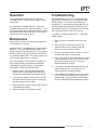
Operation
Troubleshooting
Once adjusted and installed, the IPT2 operates
unattended, except for occasional cleaning of the air
supply filters.
Many components of the IPT2 have been thermally
aged, tested, and selected using a computer-aided
design program. This usually makes field repair
unnecessary. It is therefore recommended that any
unit found to be performing below specifications be
returned to the factory in accordance with the instructions found on the back cover of this manual.
If a malfunction is isolated to the IPT2, refer to the
Troubleshooting section for recommendations. A unit
may become warm during operation, especially where
the ambient temperature is elevated. This is normal
and should not be cause for alarm.
Maintenance
After the IPT2 has been installed into the application,
no maintenance is required.
2
However, the IPT is equipped with a plunger to clean
the orifice. To use the orifice-plunger, depress the
plunger located on the side of the unit. This pushes a
stainless steel wire through the orifice and removes
any particles lodged inside. The output pressure will
fluctuate when the plunger is activated.
If the plunger doesn't fix the problem, the supply air
filter screen should be removed and flushed with
trichloroethance (TCE) and then air dried before
replacement. Follow the directions below.
1. Remove the IPT2 from the mounting block by
pressing down on the locking lever and pulling
straight out to disengage the pneumatic fittings.
2. To remove the supply air filter screen, first slide
the nozzle retainer clip to the right and then pull
the nozzle out of the main body.
If a problem is suspected with the IPT2, review the
following steps:
1. Make sure that all connections are clean and
tight.
2. Verify that bench instruments used to take
measurements have the proper range and
accuracy and are currently certified.
3. Check that the bleed-air port (located in a slot on
the right side panel) is not restricted.
4. Using a test jumper, connect one end to the metal
case and the other end to an "IN" terminal while
observing the output pressure. The output
pressure should not change.
5. If a change in the relationship between the input
and the output occurs, try to correct it by readjusting the Zero and Span controls.
6. If the response time lengthens or the span drops,
this may indicate a blockage due to air supply
contamination. Clean the orifice and the supply
air filter as described in the Maintenance section.
3. Remove the filter screen and flush with TCE and
air dry before reinstalling.
4. Slide the nozzle back into the main body.
The Interface Solution Experts
9
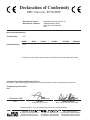
Declaration of Conformity
EMC Directive 89/336/EEC
• Manufacturer’s Name:
• Manufacturer’s Address:
Moore Industries-International, Inc.
16650 Schoenborn Street
North Hills, CA 91343-6196
USA
Declares that the product(s):
• Product Name:
IPT2
MODEL /
• Model Number(s):
IPT2
INPUT
/
OUTPUT
*
*
/
POWER
*
/
OPTIONS
/
HOUSING
*
*
*Indicates any input, output, power, options and housing as listed on product data sheet
• Conforms to the following EMC specifications:
EN 61326-1, 1998, Electromagnetic Compliance (EMC) requirements for electrical equipment for control use
• Supplementary Information:
None
2 December 2002
Date
Fred Adt
Quality Assurance Director
Robert Stockham
Moore Industries-Europe General Mgr.
European Contact: Your Local Moore Industries Sales and Service Office
United States • [email protected]
Tel: (818) 894-7111 • FAX: (818) 891-2816
Australia • [email protected]
Tel: (02) 8536-7200 • FAX: (02) 9525-7296
Belgium • [email protected]
Tel: 03/448.10.18 • FAX: 03/440.17.97
The Netherlands • [email protected]
Tel: (0)344-617971 • FAX: (0)344-615920
China • [email protected]
Tel: 86-21-62491499 • FAX: 86-21-62490635
United Kingdom • [email protected]
Tel: 01293 514488 • FAX: 01293 536852
RETURN PROCEDURES
To return equipment to Moore Industries for repair, follow these four steps:
1. Call Moore Industries and request a Returned Material Authorization (RMA) number.
Warranty Repair –
If you are unsure if your unit is still under warranty, we can use the unit’s serial number
to verify the warranty status for you over the phone. Be sure to include the RMA
number on all documentation.
Non-Warranty Repair –
If your unit is out of warranty, be prepared to give us a Purchase Order number when
you call. In most cases, we will be able to quote you the repair costs at that time.
The repair price you are quoted will be a “Not To Exceed” price, which means that the
actual repair costs may be less than the quote. Be sure to include the RMA number on
all documentation.
2. Provide us with the following documentation:
a) A note listing the symptoms that indicate the unit needs repair
b) Complete shipping information for return of the equipment after repair
c) The name and phone number of the person to contact if questions arise at the factory
3. Use sufficient packing material and carefully pack the equipment in a sturdy shipping
container.
4. Ship the equipment to the Moore Industries location nearest you.
The returned equipment will be inspected and tested at the factory. A Moore Industries
representative will contact the person designated on your documentation if more information is
needed. The repaired equipment, or its replacement, will be returned to you in accordance with
the shipping instructions furnished in your documentation.
WARRANTY DISCLAIMER
THE COMPANY MAKES NO EXPRESS, IMPLIED OR STATUTORY WARRANTIES (INCLUDING ANY WARRANTY OF MERCHANTABILITY OR OF FITNESS
FOR A PARTICULAR PURPOSE) WITH RESPECT TO ANY GOODS OR SERVICES SOLD BY THE COMPANY. THE COMPANY DISCLAIMS ALL WARRANTIES ARISING FROM ANY COURSE OF DEALING OR TRADE USAGE, AND
ANY BUYER OF GOODS OR SERVICES FROM THE COMPANY ACKNOWLEDGES THAT THERE ARE NO WARRANTIES IMPLIED BY CUSTOM OR
USAGE IN THE TRADE OF THE BUYER AND OF THE COMPANY, AND THAT
ANY PRIOR DEALINGS OF THE BUYER WITH THE COMPANY DO NOT IMPLY THAT THE COMPANY WARRANTS THE GOODS OR SERVICES IN ANY
WAY.
ANY BUYER OF GOODS OR SERVICES FROM THE COMPANY AGREES
WITH THE COMPANY THAT THE SOLE AND EXCLUSIVE REMEDIES FOR
BREACH OF ANY WARRANTY CONCERNING THE GOODS OR SERVICES
SHALL BE FOR THE COMPANY, AT ITS OPTION, TO REPAIR OR REPLACE
THE GOODS OR SERVICES OR REFUND THE PURCHASE PRICE. THE
COMPANY SHALL IN NO EVENT BE LIABLE FOR ANY CONSEQUENTIAL OR
INCIDENTAL DAMAGES EVEN IF THE COMPANY FAILS IN ANY ATTEMPT
TO REMEDY DEFECTS IN THE GOODS OR SERVICES , BUT IN SUCH CASE
THE BUYER SHALL BE ENTITLED TO NO MORE THAN A REFUND OF ALL
MONIES PAID TO THE COMPANY BY THE BUYER FOR PURCHASE OF THE
GOODS OR SERVICES.
ANY CAUSE OF ACTION FOR BREACH OF ANY WARRANTY BY THE
COMPANY SHALL BE BARRED UNLESS THE COMPANY RECEIVES
FROM THE BUYER A WRITTEN NOTICE OF THE ALLEGED DEFECT OR
BREACH WITHIN TEN DAYS FROM THE EARLIEST DATE ON WHICH THE
BUYER COULD REASONABLY HAVE DISCOVERED THE ALLEGED DEFECT OR BREACH, AND NO ACTION FOR THE BREACH OF ANY WARRANTY SHALL BE COMMENCED BY THE BUYER ANY LATER THAN
TWELVE MONTHS FROM THE EARLIEST DATE ON WHICH THE BUYER
COULD REASONABLY HAVE DISCOVERED THE ALLEGED DEFECT OR
BREACH.
RETURN POLICY
For a period of thirty-six (36) months from the date of shipment, and under
normal conditions of use and service, Moore Industries ("The Company") will
at its option replace, repair or refund the purchase price for any of its manufactured products found, upon return to the Company (transportation charges
prepaid and otherwise in accordance with the return procedures established
by The Company), to be defective in material or workmanship. This policy
extends to the original Buyer only and not to Buyer's customers or the users
of Buyer's products, unless Buyer is an engineering contractor in which case
the policy shall extend to Buyer's immediate customer only. This policy shall
not apply if the product has been subject to alteration, misuse, accident, neglect or improper application, installation, or operation. THE COMPANY
SHALL IN NO EVENT BE LIABLE FOR ANY INCIDENTAL OR CONSEQUENTIAL DAMAGES.
United States • [email protected]
Tel: (818) 894-7111 • FAX: (818) 891-2816
Australia • [email protected]
Tel: (02) 8536-7200 • FAX: (02) 9525-7296
© 2005 Moore Industries-International, Inc.
Belgium • [email protected]
Tel: 03/448.10.18 • FAX: 03/440.17.97
The Netherlands • [email protected]
Tel: (0)344-617971 • FAX: (0)344-615920
China • [email protected]
Tel: 86-21-62491499 • FAX: 86-21-62490635
United Kingdom • [email protected]
Tel: 01293 514488 • FAX: 01293 536852
Specifications and Information subject to change without notice.