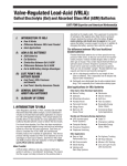
1
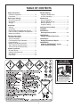
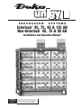
®
S P A C E S A V E R®
SYSTEMS
Interlock 45, 75, 95 & 125 AH
Non-Interlock 45, 75 & 95 AH
™
™
Installation and Operation Manual
California
Proposition 65
Warning:
Batteries, battery posts, terminals and related accessories
contain lead and lead compounds, and other chemicals known
to the state of California to cause cancer and birth defects or
other reproductive harm. Wash hands after handling.
TABLE OF CONTENTS
Safety Precautions
Protective Equipment ......................................3
Procedures ......................................................3
Record Keeping
Voltages, Temperatures
& Ohmic Readings ..........................................6
Receiving & Storage
Receiving Inspection........................................3
Unpacking ........................................................3
Storage ............................................................3
Maintenance
Annual Inspection ............................................7
Rectifier Ripple Voltage....................................7
Battery Cleaning ..............................................7
Capacity Testing ..............................................7
Installation
Cell Removal Procedure..................................7
General ............................................................4
Grounding ........................................................4
Electric Code for Maintenance Access ............4
Floor Anchoring & Module Arrangements ......4
Module Installations ........................................4
FIGURES ......................................................7-17
APPENDIX A
Recharge Interval Chart ..............................18
APPENDIX B
Voltage Compensation Chart......................19
Electrical Connection
Connector Assembly........................................4
Terminal Assembly ..........................................4
Final Assembly Check Procedure ......................5
Parallel Strings ................................................5
Module Front Shield Assembly ........................5
Top Protective Shield Assembly ......................5
Terminal Plate Shield Assembly ......................5
APPENDIX C
Battery Maintenance Report ......................20
APPENDIX D
UNIGY II SPACESAVER® System
Acid Volumes & Weights ............................21
System Operations
Charger Voltage ..............................................6
Operating Temperatures ................................6
Cell Voltage ......................................................6
Equalizing ........................................................6
BATTERIES
AND RELATED PARTS
CONTAIN LEAD
WASH HANDS
AFTER
HANDLING!
CALIFORNIA PROPOSITION 65 WARNING:
Batteries, battery posts, terminals and related
accessories contain lead and lead compounds, and
other chemicals known to the state of California to cause
cancer and birth defects or other reproductive harm.
California Proposition 65 Workplace Warning Sign
Must be posted in workplace near batteries.
2
7/04
SAFETY PRECAUTIONS
DANGER
VRLA (Valve Regulated Lead-Acid) batteries have the
electrolyte immobilized within the cell; however, electrical
hazard associated with batteries still exists. Work performed
on these batteries should be done with the tools and the
protective equipment listed below. VRLA battery
installations should be supervised by personnel familiar
with batteries and battery safety precautions.
HIGH VOLTAGE...
RISK OF SHOCK.
DO NOT TOUCH
UNINSULATED
TERMINALS OR
CONNECTORS.
SHIELD
EYES.
EXPLOSIVE
GASES CAN CAUSE
BLINDNESS OR INJURY.
SULFURIC
ACID
CAN
NO
•SPARKS CAUSE
•FLAMES BLINDNESS OR
•SMOKING SEVERE BURNS.
WARNING: Risk of fire, explosion or burns. Do not
disassemble, heat above 40°C, or incinerate.
Protective Equipment
FLUSH EYES
IMMEDIATELY
WITH WATER.
GET
MEDICAL
HELP
FAST.
SEE INSTALLATION, MAINTENANCE AND OPERATION
INSTRUCTIONS FOR IMPORTANT SAFETY PRECAUTIONS.
Although VRLA batteries can vent or leak small amounts of
electrolyte, electrical safety is the principle but not the only
concern for safe handling. Per IEEE 1188 recommendations, the
following minimum set of equipment for safe handling of the
battery and protection of personnel shall be available:
1. Safety glasses with side shields, or goggles, or face shields
as appropriate. (Consult application specific requirements)
2. Electrically insulated gloves, appropriate for the installation.
3. Protective aprons and safety shoes.
4. Portable or stationary water facilities in the battery vicinity for
rinsing eyes and skin in case of contact with acid electrolyte.
5. Class C fire extinguisher.
6. Acid neutralizing agent.
7. Adequately insulated tools.
8. Lifting devices of adequate capacity, when required.
VENTILATE WELL WHEN IN AN ENCLOSED
SPACE AND WHEN CHARGING.
DO NOT REMOVE VENT VALVE.
WARRANTY VOID IF VENT VALVE IS REMOVED.
California
Proposition 65
Warning:
Batteries, battery posts, terminals and related accessories
contain lead and lead compounds, and other chemicals known
to the state of California to cause cancer and birth defects or
other reproductive harm. Wash hands after handling.
Fig. 1-1
RECEIVING & STORAGE
Receiving Inspection
Upon receipt, and at the time of actual unloading, each
package should be visually inspected for any possible
damage or electrolyte leakage. If either is evident, a more
detailed inspection of the entire shipment should be
conducted and noted on the bill of lading. Record receipt
date, inspection data and notify carrier of any damage.
Procedures
The following safety procedures should be followed during installation:
(Always wear safety glasses or face shield when working on or
near batteries. Refer to Figure 1)
1. These batteries are sealed and contain no free electrolyte. Under
normal operating conditions, they do not present any sulfuric
acid danger. However, if the battery jar or cover is damaged,
sulfuric acid could be present. Sulfuric acid is harmful to the
skin and eyes. Flush affected area with water immediately and
consult a physician if splashed in the eyes. Consult SDS for
additional precautions and first aid measures.
SDS sheets can be obtained at www.eastpennmanufacturing.com.
2. Prohibit smoking and open flames, and avoid arcing in the
immediate vicinity of the battery.
3 Do not wear metallic objects, such as jewelry, key chains, while
working on batteries. Do not store un-insulated tools in pockets
or tool belt while working in vicinity of battery.
4. Keep the top of the battery dry and clear of tools and other
foreign objects.
5. Provide adequate ventilation (per IEEE standard 1187 and/or
Federal, State & Local codes) and follow recommended
charging voltages.
6. Never remove or tamper with the pressure relief valves, unless
for cell removal. Warranty void if vent valve is removed.
7. Inspect all flooring and lifting equipment for functional adequacy.
8. Adequately secure battery modules, racks, or cabinets to the floor.
9. Connect support structures to ground system in accordance with
applicable codes.
10. The below IEEE Standards contain additional information. Other
standards may be relevant to your specific application.
Unpacking
1. Always wear eye protection.
2. Check all batteries for visible defects such as cracked
containers, loose terminal posts, or other unrepairable
problems. Batteries with these defects must be replaced.
3. Check the contents of the packages against the packaging
list. Report any missing parts or shipping damage to your
East Penn agent or East Penn Mfg. Co. immediately.
4. Never lift batteries by the terminal posts.
5. When lifting batteries, the proper equipment is needed such
as a forklift or a portable crane. Always check the lifting
capacities of the equipment being used and never lift more
than one module and or cell at a time.
Storage
1. Cells should be stored indoors in a clean, level, dry, cool
location. Recommended storage temperature is 0°F to 90°F
(–18°C to 32°C).
2. Stored lead-acid batteries self discharge and must be given a
boost charge to prevent permanent performance degradation.
0°F to 77°F (-18°C to 25°C) storage: Batteries should be
recharged six months from date of manufacture.
>77°F (25°C) storage: Use the chart in Appendix A for recharge
intervals. Voltage readings should be taken on a monthly basis.
Cells that reach 2.10 volts per cell should be recharged
regardless of scheduled interval. Record dates and conditions
for all charges during storage.
3. If a boost charge is required: the recommended charge is 24
hours at a constant voltage equal to 2.40 volts per cell.
4. Do not store beyond 12 months.
5. Store in horizontal position only.
IEEE 1187 – Recommended Practice for Installation Design of VRLA Batteries
IEEE 1188 – Recommended Practice for Maintenance, Testing, of VRLA Batteries
IEEE 1189 – Selection of VRLA Batteries for Stationary Applications
3
Connector Assembly (con’t)
INSTALLATION
General
2. The Interlock™ and Non-Interlock™ battery (45, 75 &
95 AH) are supplied with connector package “1CU”
requiring one connector per post. Install the connectors
loosely to allow for final alignment, then torque to
125 ± 5 inch pounds (14.1 ± .5 Nm.) The installation
and direction of the post bolts is important! (Refer to
Fig. 4-1, 4-2 and 4-3 pg. 11 and 12; Fig. 4-4, pg. 4.
For proper direction when inserting into posts.) The
125 AH battery is supplied with a 2CU connector
package as standard. (Refer to Fig.5-1A, pg. 13 for
special connector orientation for side terminal & stack
to stack connections.)
3. Batteries used in high rate discharge applications require
multiple connectors per connection. (Refer to optional
connector packages in Fig. 4-5, pg. 4)
Caution should be taken when installing batteries to insure no
damage occurs. The battery cabinet, tray, rack, etc. shall be
inspected for sharp edges that could cause damage to the
battery casing. Batteries shall not be dropped, slid, or placed on
rough or uneven surfaces such as tray lips or grated flooring.
Mishandling of batteries could result in equipment damage or
human injury. East Penn will not be liable for damage or injury
as a result of mishandling or misuse of the product.
Grounding
When grounding the battery system, proper techniques should be
applied per electrical standards, such as NEC and/or local codes,
as well as user manual of specific applications.
Two .201 diameter x .750 center holes are provided in back of each
module to accept a #6 x .750 center compression grounding lug.
The holes must be tapped for a 1/4-20UNC thread and paint must
be removed for a proper grounding pad location.
Electric Code for Maintenance Access
Refer to ANSI/NFPA-70 National Electric Code for access
and working space requirements around the battery.
A minimum of 36" aisle space is recommended in front
of the battery for service and inspection.*
*Note: Battery system and/or individual module grounding, if required, is
the installer’s responsibility.
Floor Anchoring & Module Arrangements
See East Penn Mfg. Co.’s schematic diagram illustration.
One is supplied with each shipment. If it cannot be located,
contact East Penn Mfg. Co. for a copy. Refer to your delivery
number, located on the packing slip. This will aid in obtaining
the proper drawing.
Fig. 4-4
Module Installations
Connector Packages
Assemble modules per the following details.
CAUTION: Never lift more than one module at a time with the
lifting slings. (See Fig. 3-2, pg. 9.)
1. UBC Zone 4 hardware included for Interlock™ module
assembly (45, 75 & 95 AH). (See Fig. 3-4, pg. 10)
2. Unbolt the floor-mounting channel from the top of the battery.
3. Use the two slings provided to lift modules.
Note: For Interlock™ module lift the top module slightly
and slide front. (This will release the interlock tabs and
will free itself from the remaining stack.) (See Fig. 3-2, pg. 9)
4. For the Non-Interlock modules, reference figure 3.5,
pg. 11 for marking hole locations to mount base supports to
floor. For the Interlock modules, use 1-piece base for marking
floor hole location. (See local building codes for anchor bolt
requirements, anchor bolts not included.)
5. Remove the next module in the same manner as the first.
Place in position. Note: For Interlock™ module slide back
allowing the tabs to lock in place. (No rear bolts required)
(See Fig. 3-2, pg. 9)
Standard Package (45, 75 & 95 AH)
1CU: (1) 1⁄8" connector / post
≤ 250 amps / 480 wpc (5-15 plate)
≤ 450 amps / 720 wpc (17-27 plate)
≤ 550 amps / 880 wpc (29-33 plate)
Optional Packages
2CU: (2) 1⁄8" connectors / post (Standard on 125 AH)
≤ 1000 amps / 1600 wpc (9-33 plate)
4CU: (4) 1⁄8" connectors / post
≤ 2000 amps / 3200 wpc (13-33 plate)
6CU: (6) 1⁄8" connectors / post
≤ 3000 amps / 4800 wpc (25-33 plate)
Corresponding Bolt Package
1CU: 1⁄4-20 x 11⁄4" long — JMP1428
2CU: 1⁄4-20 x 11⁄2" long — JMP1407
4CU: 1⁄4-20 x 13⁄4" long — JMP1435
6CU: 1⁄4-20 x 2" long — JMP1409
Fig. 4-5
Terminal Assembly
1. Attach the terminal mounting bracket to the module
frame. (See Fig. 5-1, pg. 13 for Interlock™ and Fig. 5-2
and 5-2A for Non-Interlock™, pg. 14 for Side Terminal;
See Fig. 5-3 and Fig. 5-3A, pg. 15 for Top Terminal)
2. Attach the terminal plates or the terminal connectors
to the battery posts and then torque to 125 ± 5 inchpounds (14.1 ± .5 Nm). (See Fig. 5-3 and Fig. 5-3A,
pg. 15 for 95 AH vs. 125 AH)
3. For cable connection assembly, (See Fig. 7-1, pg. 16
and Fig. 7-1A, pg. 17.)
6. Each battery is shipped with its own schematic. Make
sure the polarity on the batteries match the drawings.
ELECTRICAL CONNECTION
Connector Assembly
1. The contact surfaces of each individual post on every
cell have been cleaned and coated with a thin film of
no-ox-ID “A” grease at the factory. Assure the contact
surfaces are free of dust or dirt prior to assembly.
4
Final Assembly Check Procedure
Top Protective Shield Assembly
1. For future identification of all cells, number individual
cells in sequence, beginning with number one (1) at the
positive end of the battery. The last cell of the battery is
located at the negative output terminal.
2. Read and record the voltages of the individual cells to
assure that they are connected properly. The total battery
voltage should be approximately equal to the number of
cells connected in series multiplied by the measured
voltage of one cell. If the measurement is less, recheck
the connections for proper polarity. Verify that all cell and
battery connections have been properly torqued.
3. Measure and record the intercell connection resistance
using a micro-ohms meter. This helps determine the
adequacy of initial connection installation and can be
used as a reference for future maintenance requirements.
Refer to the recording forms in Appendix C of this
manual. Review the records of each connection and
detail resistance measurements. Clean, remake, and
remeasure any connection that has a resistance
measurement greater than 10% of the average of all the
same type connections (i.e. intercell, intermodule, etc.).
4. Battery performance is based on the output at the battery
terminals. Therefore, the shortest electrical connection
between the battery system and the operating equipment
results in maximum total system performance.
Select cable size based on current carrying capability and
voltage drop.
Cable size should not provide a greater voltage drop between
the battery system and operating equipment than specified.
Excessive voltage drop in cables will reduce the desired
reserve time and power from the battery system.
For side terminal assembly, attach the black top protective
cover to the highest front shield.
For top terminal assembly, cut the black protective cover to
fit between the terminals and then attach to the front shield.
(See Fig. 5-4, pg. 16.)
Terminal Plate Shield Assembly
For side terminal shield assembly, (Refer to Fig. 5-1, pg 13
for Interlock™ and Fig. 5-2 and 5-2A for Non-Interlock™,
pg. 14 and Fig. 5-7, pg. 5)
For top terminal shield assembly, (Refer to Fig. 5-3, pg. 15
and Fig. 5-8, pg. 5)
Fig. 5-6
Parallel Strings
When paralleling valve-regulated batteries, the capacity,
arrangement, and external circuit length should be identical
for each battery. Wide variation in the battery circuit
resistance can result in unbalanced charging (i.e., excessive
charging currents in some batteries and undercharging in
others). As a result, cell failures in one battery string and
subsequent loss of performance capabilities of that string
will result in higher loads in the other parallel string(s),
which may exceed the ratings of the battery connections.
This can damage the battery system and dramatically
shorten battery life.
Module Front Shield Assembly
1. Attach one black clip to each end of the clear shield.
(See Fig. 5-4, pg. 16 and 5-5, pg. 5.)
2. Install the fully assembled shield into the tabs on the
module. (See Fig. 5-6, pg. 5 & Fig. 5-4, pg. 16)
Fig. 5-7
Fig. 5-8
Fig. 5-5
5
Voltages, Temperatures & Ohmic Readings (con’t)
While it is acceptable to operate at temperatures less than
77˚F (25˚C), it will require longer charging time to become
fully recharged. Also, the capacity will be less at operating
temperatures below 77˚F (25˚C).
After installation and when the batteries have been on float
charge for one week, the following data should be recorded:
1. Battery terminal voltage
2. Charger voltage
3. Individual cell float voltages
4. Individual cell ohmic readings. On a 4-post cell place
meter leads on the left positive - left negative posts or
right positive - right negative posts. For 6-post cells,
measure from center positive - center negative posts.
Do not measure diagonally from positive to negative
posts. (See Fig. 6-1, pg. 6.)
5. Ambient temperatures
6. Terminal connections should be checked to verify that
the installer did torque all connections properly
(125 ± 5 in.-lbs.). Micro-ohm readings should be taken
across every connection. (Refer to Fig. 6-2, pg. 6)
Refer to meter manufacturer’s instructions for proper
placement of probes. If any reading differs by more
than 20% from its initial installation value, re-torque the
connection to 125 ± 5 inch-pounds. If the reading still
remains high, clean contact surfaces according to Step 2
under Connector Assembly.
SYSTEM OPERATIONS
Charger Voltage
These batteries are designed for continuous float applications.
Float / Standby
2.25 vpc ± 0.01 @ 77°F (25°C)
When setting the float voltage on the charger, the system should be
set to float at the nominal cell float voltage times the number of
cells per string. The charger must be able to maintain the system
voltage within ± 0.5% of the desired level at all times. The desired
float voltage varies with temperature according to the table in the
next column.
Temperature Compensation
Battery voltage should be adjusted for ambient temperature
variations.
2mV per °C (1.8°F) per cell
Consult Voltage Compensation Chart in Appendix B for
temperature compensation voltage maximum and minimum limits
Battery Operation
Battery operating temperature will affect battery capacity and
operating life.
Operation at temperatures greater than 77°F (25°C) will reduce
the operating life of the battery. For every 13°F (7°C) increase in
operating temperature above 77°F (25°C), the warranty period
will be proportionally reduced by 50% as shown below:
Operating Temp.
Proportional % of Life
77°F (25°C)
100%
81°F (27°C)
80%
87°F (30°C)
60%
90°F (32°C)
50%
The average cell operating temperature should not exceed 95°F
(35°C) and should never exceed 105°F (40.5°C) for more than an
eight-hour period. If operating temperatures are expected to be in
excess of 95°F (35°C), contact East Penn for recommendations.
Discharging at temperatures less than 77°F (25°C) will reduce the
capacity of the battery.
Cells must not be operated below 50°F (10°C). If operating
temperatures are expected to be less than 50°F (10°C),
contact East Penn for recommendations.
Batteries must be located in a manner that the individual cells do
not vary by more than 5°F (2.8°C) between the lowest and highest
individual cell temperatures.
Cell Voltage
Fig. 6-1
Although the charger must maintain the system voltage
within ± 0.5%, individual battery [cell] voltages may vary by
± 0.05 volts per cell of the average cell float voltage.
Equalizing
Upon installation of the battery system, an optional charge of
14.40V per battery ± 0.06 @ 77°F (25°C) [2.40 vpc ± 0.01 @
77°F (25°C)] for 24 hours (not to exceed 24 hours) can be
applied. (Note: Verify that the higher battery voltage will not
adversely affect any other connected equipment). If this is
done, be sure to reset the charging equipment to the
proper float voltage.
RECORD KEEPING
Voltages, Temperatures & Ohmic Readings
Record keeping is an important part of stationary battery
maintenance and warranty coverage. This information will
help in establishing a life history of the battery and inform
the user if and when corrective action needs to be taken.
(Refer to Appendix C, Battery Maintenance Report)
Fig. 6-2
6
Failure to maintain proper records including information as
detailed above may result in voiding any applicable warranty.
MAINTENANCE
CELL REMOVAL PROCEDURE
Always wear eye protection when working on or near
batteries. Keep sparks and open flames away from batteries
at all times. See Safety Precautions on pg. 3.
Annual Inspection
1. Before removing cells, review Safety Precautions on
pg. 3 of this manual. Contact East Penn Manufacturing
Company, Inc. with specific questions or concerns.
2. Refer to Fig. 8-1 through 8-4 below for specific
instructions.
(1)
1. Conduct a visual inspection of each cell.
2. Record the battery string voltage.
3. Record the charger voltage.
4. Record the individual cell voltages. The accuracy of the
DMM (Digital Multimeter) must be .05% (on dc scale)
or better. The DMM must be calibrated to NIST traceable
standards. Because float readings are affected by discharges and recharges, these readings must be taken
when batteries have been on continuous, uninterrupted
float for at lease one month. Cells should be within
± 0.05 volts of the average cell float voltage.
5. Record the ambient temperatures.
6. Record individual cell ohmic readings.
7. Record all interunit and terminal connection resistances.
Micro-ohm readings should be taken during this
inspection. If any reading differs by more than 20% from
initial readings taken, retorque the connection. Recheck
the micro-ohm reading. If the reading remains high,
clean the contact surface according to installation portion
of this manual.
(1)
Other Maintenance Inspection intervals follow
IEEE 1188
STEP 1: HARDWARE REMOVAL
1. DISCONNECT CHARGER.
2. DISCONNECT THE SYSTEM
GROUND CONNECTION.
3. REMOVE MODULE FRONT SHIELD
ASSEMBLY. REMOVE THE CELL
RETAINER BAR.
4. DISCONNECT THE CELL FROM
OTHER CELLS IN SERIES.
CONNECTOR
RETAINER
BAR
1/4-20 X 1" LG THREAD
CUTTING SCREW (INTERLOCK)
1/4-20 HEX NUT (STANDARD)
Fig. 8-1
STEP 2: PRESSURE RELIEF
1. PRY VENT SHROUD OFF.
2. REMOVE FLAME ARRESTOR.
3. UNSCREW VALVE WITH 17mm
HEX KEY. (PRESSURE WILL RELEASE)
4. RETORQUE VALVE IMMEDIATELY TO
12-14 in.lbs. WITH 17mm HEX KEY.
Rectifier Ripple Voltage
CATALYST VALVE
FREQUENCY
Ripple that has a frequency greater than 667Hz (duration
less than 1.5ms) is acceptable, unless it is causing additional
battery heating.
Ripple that has a frequency less than 667Hz (duration
greater than1.5ms), must meet the following voltage
specification to be acceptable.
VOLTAGE
Ripple voltage shall be less than 0.5% peak to peak of the
manufacturer’s recommended string voltage.
Failure to comply can void the warranty.
FLAME ARRESTOR
SHROUD
Fig. 8-2
STEP 3: CELL REMOVAL
1. THREAD POLYPROPYLENE ROPE
THROUGH TWO TERMINALS AS
SHOWN AND KNOT.
2. PULL CELL FROM MODULE ACROSS
LIFT TRUCK AS SHOWN.
Battery Cleaning
Batteries, cabinets, racks, and modules should be cleaned
with clear water, a mixture of baking soda and water or East
Penn Mfg supplied battery cleaner (part # 00321).
Never use solvents to clean the battery.
POLYPROPYLENE
ROPE
ACID RESISTANT
GLOVE
Capacity Testing
Per IEEE 1188 “Capacity testing is used to trend battery
aging. The result of a capacity test is a calculation of the
capacity of the battery. The calculated capacity is also used
to determine if the battery requires replacement.”
Do not discharge the battery beyond the specified final
voltage. When discharging at higher rates, extra connectors
may need to be added to prevent excessive voltage drop and
/ or excessive temperature rise. When performing capacity
testing and recording data use IEEE 1188 instructions.
Should it be determined that any individual battery (ies)
[cell(s)] need to be replaced, contact East Penn.
Fig. 8-3
STEP 4: CELL REPLACEMENT
1. CHECK POLARITY ORIENTATION.
PUSH CELL BACK INTO MODULE.
2. REMOVE ROPE IF USED.
3. REPLACE RETAINER BARS.
4. REPLACE CONNECTORS.
5. REPLACE MODULE FRONT SHIELD.
6. RECONNECT SYSTEM GROUND CONNECTION.
7. RECONNECT CHARGER.
Fig. 8-4
7
SHIPPING BOX
TOP TERMINAL BRACKET
SUPPORT CHANNEL
ACCESSORY PACKAGE
SEE PARTS LIST FOR COMPONENTS
CLEAR FRONT SHIELD PACKAGE
SHIPPING BOX
PALLET
FRONT PROTECTIVE
WAFFLE BOARD
MOUNTING PLATE & 3/8 X 1 3/4" GRADE 5
BOLT ASSEMBLY, REMOVE AND DISCARD
MODULES STACK 4 HIGH MAX.
MODULES ARE STACKED IN
REVERSE ORDER FROM LAYOUT.
REMOVE ONE MODULE AT A TIME.
Fig. 2-1
2 REQUIRED FOR LIFTING
DETAIL OF STRAP ASSEMBLY
Fig. 3-1
8
Interlock™ System Leveling
When leveling Unigy II Interlock™ battery systems that are
installed with a 1-piece base support, it is critical to note that
the back channel is 3/16" shorter than the front channel.
If a level is placed across the front and rear channels, a 3/16" shim
should be placed on top of the rear channel in order to level properly.
3
"
16
3/16" SHIM
CORRECT
INCORRECT
Fig. 3-1A
TORQUE TO 50 in. lbs.
(5.6 Nm)
LIFT STRAP
TOP MODULE SLIDES INTO CUT
OUTS OF BOTTOM MODULE
(NO BOLTING NEEDED)
LOCK WASHER
3/8-16 X 1 1/4" BOLT
JOINING PLATE
TOP MODULE ONLY
MOUNTING SUPPORT
Fig. 3-2
9
LIFT STRAP
3/8-16 X 1-1/4" BOLT
FLAT WASHER
LOCK WASHER
TORQUE TO 50 in. lbs.
(5.6 Nm)
LOWER MODULE NESTS
INTO UPPER MODULE
- FASTENED WITH 3/8"
HARDWARE
BOTTOM MODULE
3/8-16 X 1-1/4" BOLT
FLAT WASHER
LOCK WASHER
MODULE SUPPORT
Fig. 3-3
NOTES:
1. HARDWARE REQUIRED TO MEET ZONE 4
CERTIFICATION (45, 75 & 95AH INTERLOCK™)
2. TORQUE REQUIREMENT: 50 FT. LBS. (67.8 Nm)
HEX NUT
ZONE 4 ONE PIECE
MOUNTING SUPPORT
LOCK WASHER
FLAT WASHER
FLAT WASHER
3/8-16 X 1" BOLT
Fig. 3-4
10
2 & 4 CELL MODULES
75 A.H.
95 A.H.
95 A.H.
X
Y
X
Y
X
Y
X
Y
11.72
16.16
20.66
25.16
29.66
34.17
–––
–––
10.64
10.64
10.64
10.64
10.64
10.64
10.64
10.64
11.72
16.16
20.66
25.16
29.66
34.17
19.07
21.32
17.74
17.74
17.74
17.74
17.74
17.74
17.74
17.74
–––
16.16
20.66
25.16
29.66
34.17
19.07
21.32
–––
20.34
20.34
20.34
20.34
20.34
20.34
20.34
–––
9.86
12.86
15.86
18.86
21.86
11.80
13.30
–––
20.34
20.34
20.34
20.34
20.34
20.34
20.34
NO. OF
PLATES
NO. OF
PLATES
5
7
9
11
13
15
17
19
3 & 6 CELL MODULES
45 A.H.
21
23
25
27
29
31
33
3 & 6 CELL MODULES
45 A.H.
2 & 4 CELL MODULES
75 A.H.
95 A.H.
95 A.H.
X
Y
X
Y
X
Y
X
Y
–––
–––
–––
–––
–––
–––
–––
10.64
10.64
10.64
10.64
10.64
10.64
10.64
23.57
25.82
28.07
30.32
32.57
34.82
37.07
17.74
17.74
17.74
17.74
17.74
17.74
17.74
23.57
25.82
28.07
30.32
32.57
34.82
37.07
20.34
20.34
20.34
20.34
20.34
20.34
20.34
14.80
16.30
17.80
19.30
20.80
22.30
23.80
20.34
20.34
20.34
20.34
20.34
20.34
20.34
1.36
.812Ø FLOOR
MOUNTING HOLES
Y
1.64 TYP. →
1.00 TYP.
X
Fig. 3-5
TORQUE TO 125 ± 5 in. lbs.
(14.1 ± .5 Nm)
FLAT WASHER
1/4-20 BOLT
* ADDITIONAL CONNECTIONS
HEX NUT
LOCK WASHER
FLAT WASHER
BOLT ASSEMBLY CONFIGURATION
* WITH THE ADDITION OF MULTIPLE CONNECTOR
PACKAGES IT IS RECOMMENDED TO ALTERNATE
CONNECTORS EVENLY USING OPPOSITE SIDE
OF TERMINAL
Fig. 4-1
11
SHORT “L” CONNECTOR
JMPL1719 (17-19 PLT.)
JMPL2127 (21-27 PLT.)
JMPL2933 (29-33 PLT.)
BOLT ASSEMBLY
JMP1407 (9-33 PLT.)
BOLT ASSEMBLY JMP1451
5 & 7 PLATE CELLS ONLY!
SPACER REQUIRED FOR
5 & 7 PLATE CELLS ONLY!
Fig. 4-2
RECOMMENDED BOLT DIRECTION
5-15 PLATE
17-27 PLATE
29-33 PLATE
NOTES: INSULATED TORQUE WRENCH
SHOULD BE PLACED ON BOLT HEAD
TO ENSURE MAXIMUM CLEARANCE.
Fig. 4-3
12
HEX NUT
STEP 1
STEP 3
LOCK WASHER
FLAT WASHER
MOUNTING BRACKET
DETAIL−A
CLEAR TERMINAL
SIDE SHIELD
TERMINAL PLATE
3/8−16 X 2 1/2” LG. BOLT
1/4−20 X 1” LG. BOLT
FLAT WASHER
FLAT WASHER
SLOTS & HOLES TO
LOCK WASHER
FIT 1/2” DIAMETER
HEX NUT
BOLTS
FLAT WASHER
SIDE TERMINAL CONNECTOR
−ASSEMBLE− AFTER MTG.
BRKT. & TERM. PLT.
1/4−20 X 5/8” LG.
PLASTIC SCREW
FINAL ASSEMBLY
SINGLE SIDE
TERMINAL CONNECTOR
2.50
1.00
STEP 2
3.00
1.19 X .56
2.25
FINAL ASSEMBLY
DOUBLE SIDE
TERMINAL CONNECTOR
.75
1.19 X .56
1.79
DETAIL−A
SIDE TERMINAL PLATE
HEX NUT
LOCK WASHER
1/4−20 X 1” LG. BOLT
FLAT WASHER
FLAT WASHER
Fig. 5-1
BOLT THROUGH TERMINAL
CONNECTOR INTO TERMINAL AS
SHOWN TO CLEAR SHIELD CLIP
DETAIL A
SCALE 0.30 : 1
DOUBLE STACK CONNECTOR ON ONE SIDE
OF TERMINAL TO CLEAR SHIELD CLIP. BOLT
THROUGH COPPER CONNECTOR INTO
TERMINAL (AS SHOWN).
DETAIL B
SCALE 0.30 : 1
Fig. 5-1A
13
NOTES:
1. REFERENCE I & O MANUAL FOR
COMPLETE CONNECTOR ASSEMBLY
2. 2CU PACKAGE ONLY
3. BATTERY SYSTEM RATED TO 2 HOUR
DISCHARGE 695 AMPS TO 1.75 END
VOLTAGE
STEP 2
CLEAR TERMINAL
SIDE SHIELD
DOUBLE SIDE TERMINAL
FINAL ASSEMBLY
1.77
2.50
4.17
1/4 X 5/8 LONG SCREW
1.00
0.58
2.64
3.00
0.94 0.88 0.34 1.19
FLAT WASHER
LOCK WASHER
HEX NUT
1.94
0.75
DETAIL - SIDE TERMINAL PLATE
MOUNTING BRACKET
TERMINAL
PLATE
3/8−16 X 4 1/2” LONG BOLT
FLAT WASHER
SIDE TERMINAL CONNECTOR
−ASSEMBLE AFTER MOUNTING
BRACKET AND TERMINAL PLT.
STEP 1
SPACER
FLAT WASHER
LOCK WASHER
HEX NUT
1/4−20 X 1” LONG BOLT
FLAT WASHER
Fig. 5-2
MOUNTING
SUPPORT
SLOT IN LOWER ARM OF MOUNTING
BRACKET SLIPS OVER TAB IN
MOUNTING SUPPORT
3/8 FLAT WASHER
LOCK WASHER
HEX NUT
MOUNTING BRACKET
3/8−16 X 4 1/2” LONG BOLT
FLAT WASHER
SPACER NEEDED FOR BOTTOM SIDE
MOUNT ONLY (SPACER IS PLACED
BETWEEN MODULE AND UPPER ARM
OF MOUNTING BRACKET)
Fig. 5-2A
14
3/8-16 X 1 1/4" BOLT
LOCK WASHER
FLAT WASHER
SHIELD ASSEMBLY SLIDES
ONTO TERMINAL BRACKET
SLIDE CLIP INTO TOP CHANNEL FROM
CUT OUT ON BACK OF CHANNEL. (APPLY
CLIPS AT BOTH ENDS OF CHANNEL.)
FLAT WASHER
LOCK WASHER
HEX NUT
FLAT WASHER
1/4-20 X 1" BOLT
FRONT & BACK
TERMINAL SHIELDS
SLIDE INTO SHIELD
JOINT
1/4-20 X 1 1/2"
STEP 1
STEP 3
STEP 2
STEP 4
FINAL ASSEMBLY
JTPR0600 TERMINAL
PLATE FOR 21 THRU 33
PLATE APPLICATION
FLAT WASHER
TERMINAL CONNECTOR
JMP3129 FOR 29-33
PLATE APPLICATION
FLAT WASHER
LOCK WASHER
HEX NUT
Fig. 5-3 (45, 75 & 95 AH)
3/8-16 X 1 1/4" BOLT
LOCK WASHER
FLAT WASHER
SHIELD ASSEMBLY SLIDES
ONTO TERMINAL BRACKET
SLIDE CLIP INTO TOP CHANNEL FROM
CUT OUT ON BACK OF CHANNEL. (APPLY
CLIPS AT BOTH ENDS OF CHANNEL.)
FLAT WASHER
1/4-20 X 1" BOLT
STEP 1
STEP 3
STEP 2
STEP 4
FLAT WASHER
LOCK WASHER
HEX NUT
FINAL ASSEMBLY
1/4-20 X 1 1/2"
FLAT WASHER
FRONT & BACK TERMINAL SHIELDS
SLIDE INTO SHIELD JOINT. SHIELD
ASSEMBLY JTSR0033 FOR 29-33
PLATE APPLICATION
JTPR2975 TERMINAL PLATE FOR
29-33 PLATE APPLICATION
FLAT WASHER
LOCK WASHER
HEX NUT
Fig. 5-3A (125 AH)
15
CUT OUT TOP PROTECTIVE SHIELD
FOR TERMINAL LOCATION
SHIELD SLIDES INTO AND
SNAPS ONTO THE CLIP
INSERT CLIP END INTO
HOLES ON MODULE
SLIDE TOP PROTECTIVE SHIELD ONTO
FRONT SHIELD ON TOP MODULES ONLY
DETAIL OF ASSEMBLED SHIELD
(2) END CLIPS AND (1) FRONT SHIELD PER ASSEMBLY
Fig. 5-4
3.00
.88
.88
1.38
1.73
1.38
1.73
.56Ø HOLE TYPE
.56Ø X 1.19 LG.
SLOT TYPE
5 THROUGH 15 PLATE POST
17 AND 19 PLATE POST
.34Ø X 1.00 LG.
SLOT TYPE
1.88
1.88
3.75
3.75
.88
HOLES & SLOTS
1.38
1.73
.88
1.38
1.73
21 THROUGH 33 PLATE POST
29 THROUGH 33 PLATE POST
(125 AH PRODUCT LINE ONLY)
NOTES:
.56 DIAMETER HOLES AND 1.19 LONG SLOT USED
FOR CABLE MOUNTING TO FIT .50 DIAMETER BOLTD
TOP TERMINATION
Fig. 7-1
16
SIDE TERMINATION
Fig. 7-1A
17
APPENDIX A
Recharge Interval Chart
18
APPENDIX B
Voltage Compensation Chart
°C
Float Voltage
Per Cell
>35
34
33
32
31
30
29
28
27
26
25
24
23
22
21
20
19
18
17
16
15
14
13
12
11
<10
2mV per °C
2.230
2.232
2.234
2.236
2.238
2.240
2.242
2.244
2.246
2.248
2.250
2.252
2.254
2.256
2.258
2.260
2.262
2.264
2.266
2.268
2.270
2.272
2.274
2.276
2.278
2.280
°F
>95
93.2
91.4
89.6
87.8
86.0
84.2
82.4
80.6
78.8
77.0
75.2
73.4
71.6
69.8
68.0
66.2
64.4
62.6
60.8
59.0
57.2
55.4
53.6
51.8
<50
19
APPENDIX C
BATTERY MAINTENANCE REPORT
Date ______________________
Company ____________________________________________________________________________________________
Address______________________________________________________________________________________________
Battery Location and/or Number ____________________________________________________________________________
No. of Cells ________ Type ________________________________ Date Mfg.____________ Date Installed____________
Charger Output__________________________
Total Battery Voltage _________________
Ambient Air Temperature ______________________°F
Panel Meter Volts ___________________
Installer___________________________________________________
INDIVIDUAL CELL READINGS
Cell
No.
Serial
No.
Volts
Cell
Ohmic
Value
Connector Cell
Ohmic
No.
Value
Serial
No.
Volts
Cell
Ohmic
Value
Connector Cell
Ohmic
No.
Value
1
21
41
2
22
42
3
23
43
4
24
44
5
25
45
6
26
46
7
27
47
8
28
48
9
29
49
10
30
50
11
31
51
12
32
52
13
33
53
14
34
54
15
35
55
16
36
56
17
37
57
18
38
58
19
39
59
20
40
60
Serial
No.
Volts
Cell
Ohmic
Value
Connector
Ohmic
Value
Remarks and Recommendations ________________________________________________________________________________________________________
____________________________________________________________________________________________________________________________________
____________________________________________________________________________________________________________________________________
____________________________________________________________________________________________________________________________________
Readings Taken By____________________________________________________________________________________________________________________
Readings should be taken at installation and at least annually thereafter.
Notation: This form must be completed and submitted with any product warranty claim.
20
APPENDIX D
Unigy II SPACESAVER System Acid Volumes & Weights
®
Cell
Size
45-5
45-7
45-9
45-11
45-13
45-15
75-5
75-7
75-9
75-11
75-13
75-15
75-17
75-19
75-21
75-23
75-25
75-27
75-29
75-31
75-33
95-7
95-9
95-11
95-13
95-15
95-17
95-19
95-21
95-23
95-25
95-27
95-29
95-31
95-33
125-33
125LG-33
Acid Wt
gm
Acid Vol
cc
1,814
2,542
3,276
4,004
4,732
5,460
2,984
4,258
5,480
6,695
7,911
9,133
10,348
11,375
12,786
14,001
15,223
16,436
17,654
18,870
20,092
4,780
6,080
7,440
8,780
10,170
11,467
12,330
14,380
15,350
16,889
18,360
19,580
20,990
22,410
33,531
33,531
1,395
1,955
2,520
3,080
3,640
4,200
2,295
3,275
4,215
5,150
6,085
7,025
7,960
8,750
9,835
10,770
11,710
12,643
13,580
14,515
15,455
3,635
4,624
5,658
6,677
7,734
8,720
9,376
10,935
11,673
12,843
13,962
14,890
15,962
17,042
25,793
26,681
* Data subject to change.
21
Acid Vol
gal
Acid Wt
lbs
Pure Acid
lbs
0.37
0.52
0.67
0.81
0.96
1.11
0.61
0.86
1.11
1.36
1.61
1.86
2.10
2.31
2.60
2.84
3.09
3.34
3.59
3.83
4.08
0.96
1.22
1.49
1.76
2.04
2.30
2.48
2.89
3.08
3.39
3.69
3.93
4.22
4.50
6.81
6.81
4.00
5.60
7.22
8.83
10.43
12.04
6.58
9.39
12.08
14.76
17.44
20.13
22.81
25.08
28.19
30.87
33.56
36.23
38.92
41.60
44.29
10.54
13.40
16.40
19.36
22.42
25.28
27.18
31.70
33.84
37.23
40.48
43.17
46.28
49.41
73.92
58.82
1.60
2.24
2.89
3.53
4.17
4.81
2.63
3.75
4.83
5.90
6.97
8.05
9.12
10.02
11.27
12.34
13.42
14.48
15.56
16.63
17.71
4.41
5.60
6.86
8.09
9.38
10.57
11.37
13.26
14.15
15.57
16.93
18.05
19.35
20.66
30.90
20.23
NOTES
22
NOTES
23
www.dekabatteries.com
East Penn Manufacturing Co.
E.P.M. Form No. 1112 Rev. 7/15
Lyon Station, PA 19536-0147
Phone: 610-682-3263
© 2015 by EPM Printed in U.S.A.
Fax: 610-682-4781
e-mail: [email protected]
All data subject to change without notice. No part of this document may be copied or
reproduced, electronically or mechanically, without written permission from the company.