1
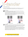
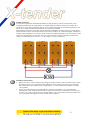
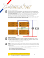
centurion akku Nederlandse Accumulatoren Productie BV Postbus 2427 6040 EA Roermond Montageweg 1 6045 JA Roermond The Netherlands telefoon : +31(475)32.41.47 telefax : +31(475)32.29.99 e-mail : [email protected] internet : http://www/centurion-akku.nl de akku met de meeste plussen User manual X-tender INDEX …………………………………………………… 2 INTRODUCTION …………………………………………………… 4 Dimensioning …………………………………………………… 4 …………………………………………………… 4 …………………………………………………… 5 …………………………………………………… 6 Capacity Size Before use Charging Commissioning Maintenance Exterior Contacts Electrolyte level Charging Charging characteristics Charging current Charging voltage Temperature “Tropical acid” When charge the battery The charging process Equalisation cabling The winter …………………………………………………… 10 Disconnecting Cleaning Charging before storage Storage in winter Storage conditions 2 X-tender and solar energy …………………………………………….. 11 The solar panel The controller Multi battery systems …………………………………………….. 12 Connection in series Requirements for connection in series Connection in parallel Requirements for connection in parallel the series / parallel connection Requirements for series / parallel connections Cabling Warning …………………………………………….. 15 3 User manual X-tender battery Introduction The X-tender from CENTURION AKKU is a ready to go battery, pre-filled and charged. This means the battery can be used immediately and will deliver its power for prolonged periods of time. Although hardly any maintenance is required, there are some guidelines. When followed, these extend the pleasure of using the X-tender to the max. Dimensioning Capacity The X-tender is suited for multiple applications but has to be dimensioned correctly. Upon choosing an X-tender, be aware of the fact that the useful capacity is 50%, next to the physical dimensions. The useful capacity depends on the amount of current taken from the battery. A calculation example on a C100 and C20: • C100: a 13W tube lamp drains 13W / 12V = 1,1 A from the battery. The capacity at the 100 hour rate of the X-tender 110 is 110Ah, which means it can supply 1,1A to the loads for 100 hours. Repeatedly discharging this deep however causes harm to the battery and reduces life. The Xtender has a safe depth of discharge of 50% which means that the light can be used uninterruptedly for 50 hours without having to recharge or damaging the battery. • C20: when the tube light mentioned above is used together with two 21W light bulbs, 13+21+21W / 12V = 4,6A is being drained from the battery. The capacity of the X-tender 110 at the 20 hour rate is 95Ah (4,75A for 20h). This means that, including the 50% safe margin, the battery can supply its energy to this setup for 10,5 hours uninterruptedly. Size The CENTURION AKKU X-tender range consists of batteries in 7 different capacities and sizes. Always try to utilize the available space to the max: it is better to use an overrated battery because: • There will always be sufficient power in reserve, also in unexpected or emergency situations. • A heavier battery is discharged less deeply when used with the same user profile than a battery with less capacity and so it will experience less strain which results in a longer life of the Xtender. Before use Charging It is advised to charge the X-tender before taking it into commission to let the X-tender provide the full potential it has been manufactured for. Even when not used, i.e. during storage, a lead battery discharges itself slowly and loses a part of the capacity that might be necessary at one point. Commissioning • The X-tender is manufactured with a robust configuration in a strong box of polypropylene. When moving, try to prevent the X-tender from bumping into sharp objects which may cause any leakages. • When using a hoist, don’t attach it to the handles as these are for manual moving only. Put the batteries on a pallet and hoist the pallet. • Prevent too sudden moves as when the tilting angle exceeds 55°, acid may be spilled when flame retarders are not fitted. 4 • • • Fit the X-tender on a well ventilated place or make sure that the tube supplied with the X-tender can exhaust into open air. When fitted on a boat, make sure seawater never can enter the battery as the salt causes poisonous chlorine gas to be formed and the battery loses its ability to be recharged. Thoroughly clean the connectors and apply some acid-free Vaseline to the terminals before connecting. Always connect the positive connector first, as the negative is mainly connected to the chassis. Accidental short circuits may be prevented this way. Maintenance Exterior Keep the exterior of the X-tender clean and dry. Moist or dirt on the lid forms a conductive path over the terminals which causes a small short circuit: the battery is able to discharge itself through this short circuit. Over prolonged periods, the battery could discharge too deeply and performance would decrease. Contact During use of the battery it is possible that lead sulphate is formed on the X-tender terminals. The formation of this compound will not harm the battery but acts as an insulator between terminal and connector and causes voltage loss. Whenever this white/blue compound is detected, clean connectors and terminals and apply some acid-free Vaseline to the terminals. Electrolyte level Dependent on frequency of charging and the type of charger, more or less water is “consumed”. Water loss is a side reaction taking place in every type of lead acid battery during charging: at the end of the charging process the potentials on positive and negative plates become very high due to polarisation and hydrogen and oxygen are being formed. With higher temperatures the rate of water loss increases. Check the electrolyte level every 3 months. The level is too low when the plates are dry or when the magic eye is transparent. Top up only AFTER charging and ONLY with demineralised/distilled water until the level: − touches the indicator (X-tender 70/90/110), − is 1 cm above the plate surface (X-tender 125) − covers the white cross of the hold downs (X-tender 140/225/280). 5 Charging The X-tender from CENTURION AKKU is a very easy-to-use battery and can be charged with practically every regular charger available and with a broad range of currents. The time necessary to charge the X-tender however, depends on the parameters of the charger used: charging characteristic, charging current, voltage and temperature. Charging characteristic There are many different kinds of battery chargers on the market. The differences are in the technology used (transformer or high frequency) and in the charging characteristic programmed: the parameters controlled during the charging process. When different parameters are controlled in subsequent steps then the charger has multiple stages. I I is the symbol of current (Ampere). When charging with an ‘I’ characteristic the charging current is kept constant and the voltage is free to increase. U The symbol U is used to indicate voltage (Volt) and is the same as V. On charging with an ‘U’ characteristic the voltage is kept constant (mostly preset by the manufacturer) and the current varies. W W is the symbol used when charging with constant power (Watt). Through the charging process, the voltage increases and the current drops, as is described in the well known formula W = U x I, also known as P = V x I. o The symbol ‘o’ means switching to a subsequent step in the charging process, with different parameters. a The ‘a’ is used to symbolise automatic switching off by a timer. IU characteristic IUoU Wa W characteristic WU characteristic IUoU is an often-used characteristic in multi stage battery chargers in which the subsequent steps have been given distinctive names: Boost (I): The charger starts by supplying a constant current to the battery, dimensioned to 10 – 20% of the 20 hour capacity of the battery. This is the actual charging step in which the bulk of the active material in the battery is converted. Absorption (U): during charging, the voltage rises. Upon reaching the preset voltage, i.e. 14,4 or 14,8V, the charger keeps the preset voltage constant for a preset period of time. During this period charging is completed, and the last percents of active material are converted. Float (oU): after completion of the charging process the charger switches to a lower voltage, i.e. 13,5V. This is a maintenance step to compensate for self discharging over prolonged periods of time. When set properly, the battery can stay connected to the charger. Wa is a charging characteristic used with simple and cheap chargers. During a fixed period the battery is charged with constant power and the charger switches off automatically. 6 Charging current The many different types of chargers also take a diversity of charging currents into account. A high initial current during boost phase shortens charging time but at a cost in efficiency. The lower the charging current the higher the efficiency, so charging current and time are not in a linear relationship. The Xtender batteries can be charged well with a charging current between 10 and 20% of the nominal 20 hour capacity. For example: the 20 hour capacity of an X-tender 110 is 95 Ah. The recommended charging current during boost is 9,5 – 19A which will be 10 – 20A in practice. Recommended charging currents for the X-tender range: X-tender 70, 90 en 110 X-tender 110, 125 en 140 X-tender 225 en 280 10 A 20 A 30 A With given currents during boost, the X-tender battery can be charged properly in 8 to 10 hours. It is recommended though to check the effectiveness and suitability of the battery charger during the first few cycles by measuring the specific gravity of the electrolyte after the charging process has been completed. Before measuring, shake the battery a few times to enable entrapped gasses to escape and to mix the electrolyte. Voltage The maximum voltage during boost and absorption is of great interest to speed and efficiency of the charging process. Where normally 14,0V is sufficient to charge the X-tender to the max, a higher end voltage shortens duration remarkably. A standard battery charger is normally preset to cut off at 14,4V during absorption and 13,5V during float. With an IUoU charger (15A/14,8V/13,5V), a 50% discharged X-tender 110 is fully charged in 10 hours at 20°C. WARNING: determination of the specific gravity directly after charging will not be accurate since gas [H2 + O2] is dissolved in the electrolyte and lack of mixing results in a much lower specific gravity reading. Keep the battery on float for a couple of days during first cycles or shake the battery before measuring to make sure the electrolyte is mixed either by convection or movement. Before measuring, disconnect the X-tender from the charger. A simple W charger is normally uncontrolled and voltage can, in theory, go endlessly high. When using such a charger determine the density of the electrolyte at regular intervals (first switch off the charger). When a specific gravity of 1,26kg/l has been reached shake the battery and determine whether a gravity of 1,28 kg/l has been reached. If so, charging time has been determined. 7 Temperature Temperature has a strong influence on the charging process: the efficiency of the charging process and side reactions as water loss and deviation from the measured or read specific gravity of the electrolyte depend on temperature: Temperature (°C) 6 13 20 27 34 Measured s.g. (kg x l-1) 1,290 1,285 1,280 1,275 1,270 Corrected s.g. (kg x l-1) at 20°C 1,280 1,280 1,280 1,280 1,280 The table above shows that the specific gravity (s.g.) diverts from the actual value at 20°C by 0.5 points every 7°C (0,005kg/l). When a specific gravity of 1,280 kg/l is measured at a temperature of 27°C, the battery is actually being overcharged because the temperature corrected value is 1,285 kg/l. This fact needs to be taken into account seriously because overcharging can damage the battery. Next to that, temperature influences the charging process in a way that for every degree of deviation from 20°C a correction should be made. The more advanced multi stage chargers come with a temperature sensor that can be mounted on terminal or case. Temperature control takes care of decreasing (above 20°C) or increasing (below 20°C) the charging voltage with 18 – 24mV/°C for a 12V setup. In practice temperature control is not necessary in the range 10°C – 30°C. Outside these boundaries temperature control is strongly recommended. Directly coupled to the fact mentioned above is the influence temperature has on side reactions like positive grid corrosion (grids are the lead support structures wich carry the active material) and water loss. The higher the temperature, the higher the water loss (gassing becomes more vigorous), the faster corrosion, and with that wear of the battery. Tropical acid When operating the X-celler at constantly higher temperatures, the battery has to be supplied with “tropical acid” in wich the electrolyte has a density of 1,240 kg/l. The advantage of the lower density lies in the fact that it is less corrosive towards grid lead than regular 1.280 kg/l battery acid. Other parameters like current / voltage on charging can be kept as if operating a “regular” X-tender. When charging? Any lead acid battery, including the X-tender, has its longest life when kept in charged condition. In practice this means that whenever there is an opportunity for changing the battery, it is best to do so: The shallower the discharging cycles, the longer the X-tender. Maximum depth of discharge in this case will be 50%. The condition of the X-tender can be determined by measuring the specific gravity of the electrolyte with a hydrometer. Also it is possible to extract the state of charge from the open circuit voltage (NOTE: the battery has to be in a depolarized condition to obtain an accurate reading). Whenever specific gravity reaches 1,180 kg/l or open circuit voltage is 12,12V, the X-tender must be charged. A deeper discharge has a negative effect on battery life. 8 The charging process During charging of the battery, discharged positive and negative active material (both lead sulphate, PbSO4), is converted into the starting materials lead dioxide (PbO2, positive) and lead (Pb, negative). In the early stages of the charging process, the specific gravity of the electrolyte is still low and so is the voltage. Because charging is an endothermic process (the conversion takes energy), the voltage needed to charge a battery is always higher than the voltage of the battery itself. As of a 70 – 80% level of charging, enough active material has been converted to allow the battery voltage to indicate ‘battery fully charged’ (end of boost step). Because of the fact that the voltage of the battery counteracts the voltage of the charger, the remaining 20% of capacity takes more time and effort to be restored . Equalisation When the X-tender is used in a stationary setup and strong cyclic application, there is a risk of stratification of the electrolyte. After finishing the absorption fase of charging, the reading of the electrolyte’s specific gravity is still low (1,240 - 1,260kg/l) when the X-tender is supposed to be fully charged. Sulphuric acid, charged back into the electrolyte, does not have the chance to diffuse fully into the solution but pockets of concentrated acid are formed. This behaviour is directly related to the low rates of gas evolution by low antimony alloys and the demand for low maintenance. The concentrated acid trapped between the plates is very corrosive and if not dispersed into the solution it can harm the grids. This phenomenon can be dealt with by applying: An equalisation step: during a short period of time, the X-tender is charged with constant current and unrestricted voltage. In doing so, hydrogen and oxygen bubbles are formed which vigorously mix the solution. A charging characteristic including equalisation would be: IUoUIoU: boost – absorption – float – equalisation – float. The amount of equalisation needed depends however on the performance of the charger used and the initial state of charging of the battery. Recommended equalisation currents are: X-tender 70 X-tender 90 X-tender 110 X-tender 125 X-tender 140 X-tender 225 X-tender 280 1,00 A 1,50 A 1,50 A 1,75 A 2,00 A 3,00 A 3,75 A float: during float a very small current (100 – 200mA) passes through the battery. Over prolonged periods of time, float maintains a circulation in the electrolyte by which mixing occurs. The effectiveness of float in preventing stratification, however, depends on temperature and has to be verified in the actual setup. Equalisation mentioned above is only necessary in stationary applications. When used is caravans, campers or yachts sailed with, the vibrations in and from the vehicles is sufficient to compensate for stratification. Wiring The wiring between the X-tender and the charger is an extremely important part of the system: thin cables get hot on high currents and cause a voltage loss. The voltage supplied to the battery is lower and charging takes more time. The optimal diameter for the cables is: current x 0,25 x meters cable. For example: for a 25A charger with 2 meters of cable to the battery a diameter of: 25 x 0,25 x 2 = 12,5mm2 is needed. When choosing between different standard diameters like 10 or 15 mm2 always take the thicker one, in this case 15 mm2. 9 Winter storage In a lot of professional applications, especially in the agricultural sector, the battery is used for only a short period of time over the year, and is stored for the rest. The X-tender can be prepared for this storage period fairly easy and be kept in top condition for serving another year. Disconnecting Most winter problems come from the fact that the battery stays connected in the circuit. Because of the fact that hardly any circuit is completely without current for whatever reasons, leakage current drains the battery over the storage period. This does not have to be a problem for the X-tender but is a source of annoyance when, on the start of a new season, it may take a long time to recharge the battery. A current leakage as small as 50mA drains an X-tender 110 to 100% DoD in 92 days. Disconnect the X-tender from the circuit by removing at least 1 connector. When the negative is connected to ground, remove the negative, when positive is connected to ground, disconnect the positive, thus preventing short circuits. Cleaning Moisture and dirt on the lid of the X-tender can form a conductive path between the terminals. Even when disconnected the battery may then discharge quickly. It is therefore important that the lid of the X-tender is kept clean and dry before storage. Cleaning with water and soap is usually sufficient. Do not use organic solvents. Apply some acid-free Vaseline to the terminals to prevent oxidation. Charging before storage After disconnecting the X-tender check the electrolyte level in the cells. Unlike topping up with water after the charging process during routine, in storage preparation it is best to top up before charging. Do not overfill however because charging increases electrolyte volume. A good electrolyte level will keep self discharging at a low rate. If possible, rock the X-tender back and forth around it’s length axis to enable entrapped gasses to escape and mix the acid. Charging is of great importance. In a cold winter and if not properly charged, the X-tenders’s electrolyte may freeze and form cracks in the battery case. A well charged X-tender with s.g. 1,280 kg/l electrolyte has the lowest freezing point: -70°C. Winter storage During the actual storage period the X-tender needs practically no attention. If the battery stays connected to a trickle charger (Vfloat = 13,2 to 13,5V) over the winter, a check of the system every 3 months will do. If a charger uses a higher Vfloat , i.e. 13,8V or if the X-tender is aged, then check the system every month until the behaviour of the system is known. When the X-tender is stored, disconnected from whatever circuit and is not trickle charged, a thorough charging every 3 months is recommended, regardless of the specific gravity of the electrolyte. A bit of overcharging is to be preferred over a partly discharged state, especially when the battery is not ready for use at the start of a new season. As soon as the specific gravity has fallen below 1,240 kg/l, the X-tender must be charged. Storage conditions High temperatures accelerate unwanted side reactions in the X-tender like for instance self-discharge. That is why the X-tender has to be stored in a dry, cool and ventilated place. When properly charged, the colder the storage conditions the better. 10 X-tender and solar energy Because of it’s charging characteristics, the X-tender is very well suited to act as a means of energy storage in solar applications, independent from grid or in off-grid applications. The solar panel In an autonomous photo-voltaic installation, in most cases the solar panels are connected in series / parallel. A regular 55W solar panel produces a maximum current of 3A at 17 Volt. Of course there are more powerfull solar panels but the concept is the same. For instance 10 solar panels can be used in parallel (dependent on the controller used): all positive and negative connections from the panels on the controller are made at the same point and the whole system can supply 17V/30Apeak. The advantage, when applied in a 2 x 5 series / parallel system, is that thinner cabling can be used because of reduced current (34V/30Apeak). Please read the documentation that comes with the solar panel / controller very carefully because wrong connections can cause severe damage to the system. 12V systeem – panelen parallel 24V systeem – panelen in serie The controller The controller of a solar installation controls both charging of the batteries and depth of discharge (DoD). The effectiveness of the deep discharge protection is however dependent on the system chosen. Often this device is nothing more than a protection against reversed polarity so that the batteries can be discharged extremely deep. An item to take into account very carefully. Often the controller can be adjusted for both charging and cut-off voltage. For setting the charging parameters follow the chapter ’charging’ of this manual. Target has to be reaching 100% state of charging during daytime: when not fully charged, discharging cycles will go deeper and deeper and the X-tender may fail prematurely. A proper setting of a deep discharge protection is a cut-off voltage of around 11,5V per 12V battery. Over the range discharge currents (C20 / C100) 11,5V corresponds with a depth of discharge of 50%. If the controller is programmable, it is best to add an equalisation step to the charging parameters to boost the X-tender to 100% once a week. 11 Multi battery systems In very small solar systems like the ones used in caravans or campers, a single X-tender provides enough energy. A more demanding application like an off-grid bungalow has a higher need for power and therefore needs more batteries. For a long battery life certain rules must be observed strictly, especially when batteries are connected in parallel. Connection in series A connection in series is been made when the power, supplied to or taken from the batteries, becomes very high and resistance of the wiring could be a problem. Compare this to i.e. the starter system of a truck versus a car: the system in a car consists of 1 starter battery in a 12V system and a starter motor of 1,2kW. The current needed to start the engine is 1200W / 12V = 100A. The engine of a truck is much heavier as is the starter motor. A break-away power of 14kW is not unusual. In a 12V / 14,4kW setup this would mean the battery has to deliver 1200A. This is not only an extremely high current for one battery, but it would also require large diameter wiring. To reduce the wiring diameters in solar applications, connection in series is usual. The scheme below shows the wiring of a 48 Volt system with 4 X-tender batteries connected in series. Compared to a 12V installation of the same power range, the current is only 25%, which means wiring diameter and cost can be reduced. In private applications 24 Volt systems are commonly used. Their layout, comprising two X-tender batteries, is comparable to the 48V system shown. Monoblock requirements For the correct functioning of X-tender batteries connected in series it is very important that performances of the connected monoblocks are equal. This means the modules have to be taken into service as a ‘set’ of the same age and type. Mixing battery types causes trouble because the smaller one is overcharged and the bigger one is starved and will lose capacity. 12 Parallel connection A connection in parallel is made when the number of solar panels in a system or the need for power exceeds the performance of a single battery. A parallel connection doesn’t increase the voltage, like a connection in series, but increases the capacity. Two X-tender 225 batteries connected in parallel act as if the set were a single 450Ah/C100 monoblock. The capacity has doubled. When making a connection in parallel, special attention is needed for the cabling used. It is of the utmost importance that ALL the wires from terminal to the central conductor are of the same length. A difference in length means a difference in resistance which results in an undercharged battery on one end of the chain and an overcharged battery on the other end. This comes from the fact that in a parallel connection the voltage is constant and current varies: V = I x R (voltage = current x resistance). Monoblock requirements • Whenever a choice CAN be made, always design a parallel system as small as possible. Still, a single monoblock system is to be preferred. Small differences in the parallel system may cause problems that could easily be prevented by using a single battery, i.e. one X-tender 225 instead of 2 X-tender 110 in parallel. • For the correct functioning of X-tender batteries connected in parallel it is very important that performances of the connected monoblocks are equal. This means the modules have to be taken into service as ‘set’ of the same age and type. Mixing battery types causes trouble because the smaller one is overcharged and the bigger one is starved and will lose capacity. 13 The series / parallel connection With a series / parallel connection the advantages of the both connection types can be combined: both voltage and capacity are being increased. Four X-tender 225 monoblocks in a series / parallel connection result in a 24V / 450Ah system. A very important but often forgotten part in a series / parallel setup is the so-called compensation cable. This cable, mounted between the series strings, takes care of voltage differences over both strings by equalisation. In an ideal situation, with 100% identical batteries, there is no current flow. ALWAYS BE VERY CAREFULL WHEN MAKING THESE CONNECTIONS AND BE SURE THEY ARE PROPERLY FUSED AND CAN BE DISCONNECTED OVER A MAIN SWITCH. A WRONG CONNECTION CAN RESULT IN A SHORT CIRCUIT AND FIRE. Monoblock requirements Certainly in this case requirements have to be met by the batteries used to make the system. When i.e. three brand new batteries are placed in a system with one older battery, performance will never exceed that of the worst one in the setup. Choose the number of batteries placed in parallel as small a possible. Use only batteries of same make, type and age. Cabling The rules for cabling of a series, parallel, or series / parallel connection are identical to those for a charger: the diameter of the cable has to match the highest current, in this case also the discharging current instead of charging current: Calculate the diameter of the cables according to the equation: [HIGHEST current] x 0,25 x metres If the result is not a standard diameter, choose for the higher standard one. Use cable lengths L1 = L2 = L3 = L4 and L5 = L6 (L1-4 do not necessarily have to match L5-6). Use the same cable type for ALL connections. Only use good quality cable without defects or damages. 14 WAARSCHUWINGEN Lead THE X- tender BATTERY CONTAINS LEAD AND SULPHURIC ACID. BOTH COMPONENTS ARE DANGEROUS TOWARDS HEALTH. ALWAYS WASH HANDS PROPERLY AFTER HANDLING A BATTERY OR ELECTROLYTE. Sulphuric acid SULPHURIC ACID IS A CORROSIVE PRODUCT. WHEN SPILLED ON SKIN IT CAN CAUSE SEVERE BURNS. IN CASE OF SKIN CONTACT IMMEDIATELY FLUSH SKIN WITH PLENTY OF WATER. USE CHEMICAL SAFETY GOGGLES AND/OR A FULL FACE SHIELD WHERE SPLASHING IS POSSIBLE. MAINTAIN EYE WASH FOUNTAIN AND QUICK-DRENCH FACILITIES IN WORK AREA. WEAR IMPERVIOUS PROTECTIVE CLOTHING, INCLUDING BOOTS, GLOVES, LAB COAT, APRON OR COVERALLS, AS APPROPRIATE, TO PREVENT SKIN CONTACT. Hydrogen HYDROGEN GAS IS GENERATED UPON OVERCHARGING AND POLYPROPYLENE CASE FAILURE. HYDROGEN GAS MAY BE FLAMMABLE OR EXPLOSIVE WHEN MIXED WITH AIR, OXYGEN, CHLORINE. AVOID OPEN FLAMES/SPARKS/OTHER SOURCES OF IGNITION NEAR BATTERY. TO AVOID RISK OF FIRE OR EXPLOSION, KEEP SPARKS OR OTHER SOURCES OF IGNITION AWAY FROM BATTERY AND DO NOT ALLOW METALLIC MATERIALS TO SIMULTANEOUSLY CONTACT NEGATIVE AND POSITIVE TERMINALS OF CELLS AND BATTERIES. Short circuit ALWAYS DISCONNECT THE NEGATIVE TERMINAL FIRST, IF COUPLED TO THE CHASSIS. AFTER DISCONNECTING THE POSITIVE TERMINAL FIRST, CONTACT WITH CHASSIS MAY STILLCAUSE A SHORT CIRCUIT. WHEN CONNECTING TO A CHARGER, FIRST CONNECT THE CLAMPS TO THE TERMINALS BEFORE SWITCHING THE CHARGER ON TO PREVENT THE FORMATION OF SPARKS. 15