Transcript
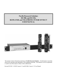
Pacific Research Solutions
RI-300 User Manual
1.6.5 MODEM INTERFACE
When selecting a modem to connect to your controller, you should be able to use about any external modem that operates at
9600 baud or higher. When setting up the modem, you want it to operate in an auto answer, dumb terminal mode. When we
were testing the modem connection to the controller, we use a US Robotics external modem for the controller. On the back of
the USR modem you will find a configuration dip-switch. Set all of the dip switches in the up position except for the switch 4
which will be down. When using other modems, use the following settings:
•
•
•
•
•
•
Data Terminal Ready (DTR)- normal
Suppress result code
No echo, off line commands (Echo Off)
Auto answer on first ring or higher depending on shared telephone line
Carrier detect - normal
Dump terminal mode, disable command recognition
For people who want to share the telephone line between the modem and the controller, we have three different methods
available:
1.
2.
3.
Ring Delay: With this method, you connect the telephone line to the modem and then connect the phone jack output
from the modem to the controller. Setup the modem to answer on 2 more rings then the controller. Example, set the
controller to answer after 2 rings and set the modem to answer after 4 rings. Then create a user command that sets SCommand 71 to mode 0, disabling incoming calls. When you want to call the modem, execute the user command and
then call the modem, controller will not answer the call. Once you are finished or during the modem connection, reset
the incoming call mode to 2 or higher. Now the controller will answer the calls before the modem.
Call switch box: This method uses a modem/voice switch box. This is a box that you will plug the telephone line, then
connect the modem port to the modem and connect the voice telephone port to the controller. When a call comes in, the
box will determine if it is for the modem or controller.
Power control: With this method, you connect the telephone line to the modem and then connect the phone jack output
to the controller. Connect a relay so that it will switch the power supply line of the modem. Use one of the controller’s
digital outputs to control the relay. Create two user command to turn the relay on and off. Set the modem to answer on
the first ring and the controller to answer on 2 or more rings. When you want to call the modem, execute the user
command to power the modem and then call the modem. Once you are finished, send the user command to power down
the modem. Now the controller will answer the calls before the modem.
Because the controller programming cable works in the same manner as a modem and in order to attach a modem to the
programming cable you need to build or purchase a modem-to-modem cable. The following schematics shows how to build a
modem-to-modem cable for a modem equipped with DB-25 connector or DB-09 connector.
02'(0
352*5$0 &$%/(
02'(0
'%3
&211(&725 0$/(
'%3
&211(&725 0$/(
'%3
&211(&725 0$/(
'%6
&211(&725 )(0$/(
352*5$0 &$%/(
5;'
7;'
'75
*1'
'65
576
&76
5;'
7;'
'75
*1'
'65
576
&76
7;'
5;'
'65
*1'
'75
&76
576
Page 21
7;'
5;'
'65
*1'
'75
&76
576