1
Pacific Research Solutions
RI-300e and RI-310e
REPEATER and TELEPHONE INTERCONNECT
USER MANUAL
This manual contains information proprietary to Pacific Research Solutions. All information is provided
solely for the operation and maintenance of the equipment described. This manual is not to be reproduced
or used for any other purpose without written authorization.
Revised 02.28.02 – RI-300 Version 2.11 and RI-300e Version 3.11 User Manual
Pacific Research Solutions
RI-300 User Manual
TABLE OF CONTENTS
SECTION 1
INTRODUCTION ..........................................................................................................1
What is the RI-300(e) Version ............................................................................................................................................. 1
Overview .............................................................................................................................................................................. 1
Feature List........................................................................................................................................................................... 1
What is an RI-310?............................................................................................................................................................... 2
SECTION 2
QUICK START ..............................................................................................................3
UNPACKING THE RI-300 ................................................................................................................................................. 3
MOUNTING THE RI-300 REPEATER CONTROLLER................................................................................................... 3
INTERFACE YOUR RECEIVER and TRANSMITTER.................................................................................................... 3
SETTING AUDIO LEVELS................................................................................................................................................ 4
Receiver Gain................................................................................................................................................................ 4
Squelch Level................................................................................................................................................................ 4
Transmitter Level .......................................................................................................................................................... 4
OPERATION ....................................................................................................................................................................... 4
INITIAL SETTINGS ........................................................................................................................................................... 4
SECTION 3
PROGRAMMING SOFTWARE ..................................................................................5
INSTALLATION................................................................................................................................................................. 5
OPERATION ....................................................................................................................................................................... 5
FLASHING the CONTROLLER’S PROGRAM ................................................................................................................. 5
PROGRAMMING SOFTWARE MENU ............................................................................................................................ 6
Main Window ............................................................................................................................................................... 6
File ................................................................................................................................................................................ 6
Controller ...................................................................................................................................................................... 7
Repeater ........................................................................................................................................................................ 7
Tone Squelch ................................................................................................................................................................ 7
Commands..................................................................................................................................................................... 7
Triggers ......................................................................................................................................................................... 8
Telephone...................................................................................................................................................................... 8
Help............................................................................................................................................................................... 8
MACRO EDITING MENU ................................................................................................................................................. 8
MODEM INTERFACE........................................................................................................................................................ 9
Vertex Programming Cable to Modem Cable ............................................................................................................... 9
U.S. Robotics 56K External Modem Set Up............................................................................................................... 10
Modem Trouble Shooting ........................................................................................................................................... 10
SECTION 4
INSTALLATION (RI-300) ..........................................................................................11
PROPER TECHNIQUES FOR QUALITY REPEATER AUDIO..................................................................................... 11
POWER SUPPLY CONNECTIONS (Pins 1 and 9).......................................................................................................... 12
REPEATER RECEIVER AUDIO CONNECTION (Pin 2)............................................................................................... 12
REPEATER TRANSMITTER AUDIO CONNECTIONS (Pin 3) .................................................................................... 12
REPEATER TRANSMITTER PTT OR TRANSMIT KEYING CONNECTION (Pin 4)................................................ 12
DCS MODULATION (Pin 11) .......................................................................................................................................... 12
DIGITAL INPUTS (Pins 6, 7 and 8) ................................................................................................................................. 13
DIGITAL OUTPUTS (Pins 13, 14 and 15) ....................................................................................................................... 13
ANALOG INPUTS (Pin 5) ................................................................................................................................................ 13
DCS DECODE AND ENCODE SET UP AND OPERATION ......................................................................................... 13
Page i
Pacific Research Solutions
SECTION 5
RI-300 User Manual
INSTALLATION (RI-310) ..........................................................................................15
VXR-5000 FREQUENCY SETUP .................................................................................................................................... 16
VXR-5000 DEFAULT LED and TX POWER MACROS................................................................................................. 16
Initialize VXR-5000DC (DC model) .......................................................................................................................... 16
Initialize VXR-5000AC (AC model) .......................................................................................................................... 16
Changing Transmitter Power Level on the VXR-5000 ...................................................................................................... 17
VXR-5000 ACCESSORY CONNECTOR “ACC” ............................................................................................................ 18
VXR-5000 INTERFACE BOARD .................................................................................................................................... 19
DAC Output access by S-Command 13 ...................................................................................................................... 19
Bit input accessed by S-Command 45......................................................................................................................... 19
Bit output controlled by S-Command 46..................................................................................................................... 19
SECTION 6
INSTALLATION (OPTIONS) ....................................................................................20
TEMPERATURE SENSOR .............................................................................................................................................. 20
INSTALLING DIGITAL VOICE RECORDER................................................................................................................ 21
INSTALLING AUDIO DELAY (AD-3) ........................................................................................................................... 21
INSTALLING THE REMOTE BASE INTERFACE (RBI-3)........................................................................................... 22
RBI-3 Jumpers ............................................................................................................................................................ 22
RBI-3 Connector Pin Out............................................................................................................................................ 23
SECTION 7
ADJUSTMENTS...........................................................................................................24
SETTING RECEIVER INPUT GAIN (R3)....................................................................................................................... 24
SETTING SQUELCH GAIN (S-COMMAND 50)............................................................................................................ 25
SMARTSQUELCH, NORMAL and EXTERNAL SQUELCH OPERATION.............................................................. 25
ADJUSTING THE REPEATER TRANSMITTER MODULATION (S-COMMAND 12) .............................................. 26
SECTION 8
OPERATION ................................................................................................................27
SYSTEM STATUS INDICATORS................................................................................................................................... 27
DTMF COMMAND INPUT.............................................................................................................................................. 28
TELEMETRY MESSAGES .............................................................................................................................................. 28
CTCSS DECODE AND ENCODE OPERATION ............................................................................................................ 29
EVENT SCHEDULER (RI-300, Version 2)...................................................................................................................... 30
Enable the “CLOCK NOT SET” Courtesy Message .................................................................................................. 30
EVENT SCHEDULER (RI-300e, Version 3) .................................................................................................................... 30
LOCAL MICROPHONE and SPEAKER .......................................................................................................................... 31
INITIALIZATION PROCEDURE .................................................................................................................................... 31
SECTION 9
INITIAL SETTINGS....................................................................................................32
User and System Command Modes.................................................................................................................................... 32
Command acknowledgment ........................................................................................................................................ 32
DEFAULT USER COMMANDS ...................................................................................................................................... 33
SETTING UP YOUR STATION ID ................................................................................................................................. 33
SET UP CTCSS/DCS DECODE ....................................................................................................................................... 36
SET CTCSS/DCS ENCODE.............................................................................................................................................. 37
YOUR CONTROLLER SERIAL NUMBER..................................................................................................................... 37
CHANGING YOUR PASSWORD.................................................................................................................................... 37
SECTION 10
AUXILIARY BUSS......................................................................................................38
CONNECTING MULTIPLE RI-300 REPEATER CONTROLLERS TOGETHER......................................................... 38
Auxiliary Buss and Programming Software ................................................................................................................ 38
Passing System Commands between Controllers ........................................................................................................ 38
SECTION 11
PROGRAMMING........................................................................................................39
PROGRAMMING COMMAND FORMAT ...................................................................................................................... 39
SPEECH READ BACK ..................................................................................................................................................... 39
PASSWORD ACCESS ...................................................................................................................................................... 39
Forgot your Password?................................................................................................................................................ 40
Some common Password problems............................................................................................................................. 40
Auxiliary Controller Password Access........................................................................................................................ 40
VALID S-COMMAND and DATA ................................................................................................................................... 41
RULES FOR LEADING ZEROS IN S-COMMANDS ..................................................................................................... 41
Page ii
Pacific Research Solutions
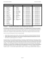
SECTION 12
S-Cmd 00
S-Cmd 01
S-Cmd 02
S-Cmd 03
S-Cmd 04
S-Cmd 05
S-Cmd 06
S-Cmd 07
S-Cmd 08
S-Cmd 09
S-Cmd 10
S-Cmd 11
S-Cmd 12
S-Cmd 13
S-Cmd 14
S-Cmd 15
S-Cmd 16
S-Cmd 17
S-Cmd 18
S-Cmd 19
S-Cmd 20
S-Cmd 21
S-Cmd 22
S-Cmd 23
S-Cmd 24
S-Cmd 25
S-Cmd 26
S-Cmd 27
S-Cmd 28
S-Cmd 29
S-Cmd 30
S-Cmd 31
S-Cmd 32
S-Cmd 33
S-Cmd 34
S-Cmd 35
S-Cmd 36
S-Cmd 37
S-Cmd 38
S-Cmd 39
S-Cmd 40
S-Cmd 41
S-Cmd 42
S-Cmd 43
S-Cmd 43
S-Cmd 44
S-Cmd 44
S-Cmd 45
S-Cmd 46
S-Cmd 47
S-Cmd 48
S-Cmd 49
S-Cmd 50
RI-300 User Manual
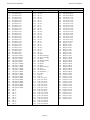
SYSTEM COMMANDS ..............................................................................................42
NO OPERATION......................................................................................................................................... 43
SYSTEM MODE.......................................................................................................................................... 43
SUB-AUDIO FILTER ENABLE ................................................................................................................. 44
USER COMMAND PREFIX SET UP (Palomar Emulation)....................................................................... 44
REPEATER CARRIER DELAY TIMER .................................................................................................... 46
FORCE PTT ON .......................................................................................................................................... 46
REPEATER TELEMETRY MODE............................................................................................................. 46
ID INTERVAL TIMER................................................................................................................................ 47
COURTESY MESSAGE TIMER ................................................................................................................ 47
LED STATUS DISPLAY ON/OFF.............................................................................................................. 47
REPEATER TIMEOUT TIMER.................................................................................................................. 48
ALTERNATE COMMAND TERMINATOR.............................................................................................. 48
ADJUST REPEATER TRANSMITTER AUDIO LEVEL .......................................................................... 49
(DAC) Digital to Analog Converter OUTPUT ............................................................................................. 49
USER AND S-COMMAND CTCSS/DCS TONE PANEL ENABLE ......................................................... 49
USER COMMAND DECODE ENABLE .................................................................................................... 50
DTMF INTER-DIGIT TIME ....................................................................................................................... 50
DTMF MUTE DELAY TIME...................................................................................................................... 50
DTMF MUTE CONTROL ........................................................................................................................... 51
GENERATE DTMF TONES ....................................................................................................................... 51
TONE PANEL CTCSS TONE and DCS CODE DECODE ENABLE ........................................................ 52
CTCSS Tone and DCS Code Number Table ................................................................................................ 53
SET MASTER and CROSS ENCODE CTCSS TONE or DCS CODE ....................................................... 53
TONE PANEL CTCSS TONE or DCS CODE ENCODE MODE............................................................... 54
INTERNAL FUNCTION CTCSS TONE or DCS CODE ENCODE........................................................... 55
SET CTCSS/DCS ENCODE LEVEL........................................................................................................... 56
DCS TX/RX DATA POLARITY CONTROL ............................................................................................. 56
CTCSS and DCS AIR TIME ........................................................................................................................ 56
TONE REMOTE DECODE SET UP ........................................................................................................... 57
TONE REMOTE MODE and NOTCH FILTER CONTROL ...................................................................... 58
RESET MESSAGES .................................................................................................................................... 60
SPEECH MESSAGE EDITOR .................................................................................................................... 60
Speech Vocabulary ....................................................................................................................................... 61
CW MESSAGE EDITOR, TONE GENERATOR COMMANDS............................................................... 64
Tone Generator Command Descriptions....................................................................................................... 65
Default Messages, Speech and Tone Generator............................................................................................ 65
Tone Generator Command List..................................................................................................................... 66
SET MESSAGE and EVENT TRIGGERS .................................................................................................. 68
DIGITAL VOICE RECORDER, EDIT MESSAGE .................................................................................... 69
AUXILIARY OUTPUT MODE................................................................................................................... 70
AUXILIARY INPUT MODE....................................................................................................................... 70
AUXILIARY INPUT CARRIER DELAY TIMER...................................................................................... 71
REGENERATE and DECODE DTMF TONES FROM the AUXILIARY INPUT ..................................... 71
MULTIPLE CONTROLLER DATA PROTOCOL and CLONING MODE ............................................... 71
RI-300 CONTROLLER UNIT ADDRESS .................................................................................................. 72
DELAY TIMER MACRO TRIGGER.......................................................................................................... 72
RECEIVER INACTIVITY TIMER MACRO TRIGGER............................................................................ 72
REGULAR INTERVAL MACRO TRIGGER ............................................................................................. 73
SET CLOCK TIME (RI-300 and RI-310 Version 2 Only)........................................................................... 73
SET REAL TIME CLOCK DATE and TIME (RI-300e and RI-310e Only) ............................................... 73
SCHEDULER TO TRIGGER A MACRO (RI-300 and RI-310 Version 2 Only) ........................................ 74
SCHEDULER TO TRIGGER A MACRO (RI-300e and RI-310e Version 3 Only) .................................... 74
LOGIC INPUTS and INTERNAL FUNCTIONS – STATE CHANGE TRIGGER .................................... 75
DIGITAL LOGIC OUTPUT, ON / OFF ...................................................................................................... 75
DIGITAL LOGIC OUTPUT PULSED ON FOR X TIME .......................................................................... 75
COUNTER TRIGGER ................................................................................................................................. 76
DIAL CLICK CONTROL TRIGGER .......................................................................................................... 76
ADJUST SQUELCH .................................................................................................................................... 77
Page iii
Pacific Research Solutions
S-Cmd 51
S-Cmd 52
S-Cmd 53
S-Cmd 54
S-Cmd 55
S-Cmd 56
S-Cmd 57
S-Cmd 58
S-Cmd 59
S-Cmd 60
S-Cmd 61
S-Cmd 62
S-Cmd 63
S-Cmd 64
S-Cmd 65
S-Cmd 66
S-Cmd 67
S-Cmd 68
S-Cmd 69
S-Cmd 70
S-Cmd 71
S-Cmd 72
S-Cmd 73
S-Cmd 74
S-Cmd 75
S-Cmd 76
S-Cmd 77
S-Cmd 78
S-Cmd 79
S-Cmd 80
S-Cmd 81
S-Cmd 82
S-Cmd 83
S-Cmd 84
S-Cmd 85
S-Cmd 86
S-Cmd 87
S-Cmd 88
S-Cmd 89
S-Cmd 90
S-Cmd 91
S-Cmd 92
S-Cmd 93
S-Cmd 94
S-Cmd 95
S-Cmd 96
S-Cmd 97
S-Cmd 98
S-Cmd 99
RI-300 User Manual
SET SQUELCH MODE ............................................................................................................................... 77
DETAIL SQUELCH SET UP ...................................................................................................................... 78
TELEPHONE HYBRID ADJUSTMENT .................................................................................................... 79
SET KEY-CODE FOR USER COMMANDS.............................................................................................. 79
PASSWORD FOR S-COMMAND ACCESS............................................................................................... 79
PASSWORD FOR TELEPHONE INCOMING RING ACCESS ................................................................ 80
PASSWORD FOR TELEPHONE INCOMING CONTROL ACCESS ....................................................... 80
REMOTE SOFTWARE RESET .................................................................................................................. 80
REMOTE EEPROM INITIALIZE ............................................................................................................... 81
RESERVED FOR FUTURE COMMAND................................................................................................... 81
RESERVED FOR FUTURE COMMAND................................................................................................... 81
DEFINING USER COMMANDS ................................................................................................................ 82
MACRO EDITOR, SET STARTING LINE NUMBER POINTER............................................................. 84
MACRO EDITOR, INSERT S-COMMANDS ............................................................................................ 84
CONDITIONAL STATEMENTS (IF / THEN / ELSE)............................................................................... 85
READ / WRITE / PUSH / POP SYSTEM DATA ....................................................................................... 88
CALL MACRO LINE .................................................................................................................................. 88
MACRO LINE JUMP .................................................................................................................................. 88
EXIT S-COMMAND PROGRAMMING .................................................................................................... 89
TELEPHONE OUTGOING CALL MODE ................................................................................................. 89
TELEPHONE INCOMING CALL MODE .................................................................................................. 90
TELEPHONE CTCSS/DCS TONE PANEL ENABLE ............................................................................... 91
TELEPHONE INCOMING CALL CONTROL TIME-OUT....................................................................... 91
INCOMING CALL RING AND COMMAND PASSWORD TIME-OUT.................................................. 91
TELEPHONE INCOMING RING DELAY................................................................................................. 91
TELEPHONE TX RING LIMIT .................................................................................................................. 92
TELEPHONE OFF-HOOK TIME-OUT TIMER......................................................................................... 92
TELEPHONE INACTIVITY ON RECEIVER TIME-OUT TIMER........................................................... 92
TELEPHONE INCOMING AGC AUDIO LEVEL ..................................................................................... 93
FLASH HOOK SWITCH ............................................................................................................................. 93
TELEPHONE DTMF OR PULSE DIALING SELECT............................................................................... 93
TELEPHONE ON/OFF-HOOK AND ACCESS/ACCOUNT CODE .......................................................... 94
EDIT TELEPHONE ACCESS and ACCOUNT CODES ............................................................................ 94
TELEPHONE NUMBER AUTO-DIALER ................................................................................................. 95
SET AN AUTO-DIAL NUMBER FOR USE............................................................................................... 95
TELEPHONE NUMBER ACCEPT TABLE ENABLE............................................................................... 95
EDIT TELEPHONE NUMBER ACCEPT TABLE ..................................................................................... 96
TELEPHONE NUMBER REJECT TABLE ENABLE................................................................................ 96
EDIT TELEPHONE NUMBER REJECT TABLE ...................................................................................... 97
WAIT FOR DIAL TONE TIMER................................................................................................................ 97
SET TRANSMIT and RECEIVE FREQUENCY......................................................................................... 98
SELECT TYPE OF SYNTHESIZED RADIO ............................................................................................. 98
SET TX OFFSET and BAND LIMITS FOR SYNTHESIZED RADIO ...................................................... 99
SET CHANNEL STEPS............................................................................................................................... 99
CHANNEL INCREMENT/DECREMENT.................................................................................................. 99
GENERIC DATA and DHE RBI-1 INTERFACE ..................................................................................... 100
RESERVED FOR FUTURE COMMAND................................................................................................. 101
RESERVED FOR FUTURE COMMAND................................................................................................. 102
USER SCRATCH PAD DATA.................................................................................................................. 102
Page iv
Pacific Research Solutions
SECTION 13
RI-300 User Manual
USER COMMANDS and MACROS........................................................................103
DEFINITION of TERMS ................................................................................................................................................ 104
PROGRAMMING STANDARD USER COMMANDS and MACROS ......................................................................... 105
Example of programming a standard user command and macro ............................................................................... 106
Example of programming macro data into the macro data memory:......................................................................... 106
Passing S-Commands to Another Controller............................................................................................................. 107
Using Conditional Statements (IF-THEN-ELSE) ..................................................................................................... 107
TELEPHONE COMMANDS .......................................................................................................................................... 109
USER S-COMMANDS.................................................................................................................................................... 109
WILDCARD COMMANDS ............................................................................................................................................ 109
EXITING PROGRAMMING MODE.............................................................................................................................. 109
SECTION 14
MESSAGES, SPEECH and CW...............................................................................110
PROGRAMMING CW MESSAGES .............................................................................................................................. 110
CW Message memory usage ..................................................................................................................................... 110
CW Messages within a user command macro ........................................................................................................... 110
Default CW station ID example ................................................................................................................................ 110
Custom tone generator CW message example .......................................................................................................... 112
PROGRAMMING SPEECH MESSAGES ...................................................................................................................... 112
Speech Message memory usage ................................................................................................................................ 112
CW Messages within a user command macro ........................................................................................................... 113
Speech message example .......................................................................................................................................... 113
EXITING PROGRAMMING MODE.............................................................................................................................. 114
SECTION 15
TELEPHONE INTERCONNECT ...........................................................................115
TELEPHONE Automatic Gain Control ........................................................................................................................... 115
DIALING PROCESS ....................................................................................................................................................... 115
TELEPHONE INCOMING CALLS ................................................................................................................................ 115
TELEPHONE USER COMMANDS ............................................................................................................................... 116
TELEPHONE INCOMING CONTROL.......................................................................................................................... 116
TELEPHONE OUTGOING CALLS ............................................................................................................................... 116
Account Codes .......................................................................................................................................................... 116
Shared telephone line ................................................................................................................................................ 116
AUTO-DIALER and LAST NUMBER REDIAL............................................................................................................ 117
TELEPHONE NUMBER ACCEPT and REJECT TABLES........................................................................................... 117
TELEPHONE COMPANY INFORMATION ................................................................................................................. 117
SETTING UP and PROGRAMMING the TELEPHONE INTERCONNECT................................................................ 118
TELEPHONE TONE REMOTE OPERATION .............................................................................................................. 118
Dial up Tone Remote Linking................................................................................................................................... 118
Two Wire Tone Remote............................................................................................................................................ 119
Page v
Pacific Research Solutions
SECTION 16
RI-300 User Manual
LINKING and REMOTE BASE...............................................................................120
EXAMPLES OF LINKING ............................................................................................................................................. 120
THE CONTROLLER’S AUXILIARY BUSS ARCHITECTURE .................................................................................. 121
SETTING UP AUDIO CHANNELS ............................................................................................................................... 122
PASSING S-COMMANDS BETWEEN CONTROLLERS ............................................................................................ 122
LINK SET UP .................................................................................................................................................................. 123
REMOTE BASE SET UP ................................................................................................................................................ 123
CONTROL RECEIVER................................................................................................................................................... 123
INTERFACING to the Doug Hall Electronics (DHE) RBI-1 .......................................................................................... 124
Connecting to the DHE RBI-1 .................................................................................................................................. 124
DHE RBI-1 to Pacific Research RBI-3 Cable ............................................................................................ 124
DHE RBI-1 to Vertex VXR-5000 ACC Cable ........................................................................................... 124
Hardware Setup......................................................................................................................................................... 124
Initial Settings ........................................................................................................................................................... 125
Operation................................................................................................................................................................... 125
Adjustments............................................................................................................................................................... 125
Customizing User Commands ................................................................................................................................... 126
Link Courtesy Messages ............................................................................................................................. 126
Link Off Command ..................................................................................................................................... 126
Link RX Command ..................................................................................................................................... 127
Link TX Command ..................................................................................................................................... 127
VFO Frequency Read Back ........................................................................................................................ 127
VFO Frequency Command ......................................................................................................................... 128
Memory Channel Select Command ............................................................................................................ 128
CTCSS Encode Select Command ............................................................................................................... 128
Power Select Command .............................................................................................................................. 129
User Function Command ............................................................................................................................ 129
PALOMAR COMMAND FORMAT............................................................................................................................... 130
Controlling from the main repeater port.................................................................................................................... 130
Controlling from a link port ...................................................................................................................................... 130
SECTION 17
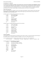
CIRCUIT DESCRIPTIONS......................................................................................131
CONTROLLER BLOCK DIAGRAM ............................................................................................................................. 131
ANALOG CIRCUIT BOARD DESCRIPTION .............................................................................................................. 132
ANALOG CIRCUIT BOARD CONFIGURATION JUMPERS ..................................................................................... 133
ANALOG CIRCUIT BOARD SCHEMATIC ................................................................................................................. 134
ANALOG CIRCUIT BOARD ASSEMBLY ................................................................................................................... 135
Central Processing Unit (CPU) CIRCUIT BOARD......................................................................................................... 136
CPU CIRCUIT BOARD CONFIGURATION JUMPERS .............................................................................................. 137
CPU BOARD SCHEMATIC ........................................................................................................................................... 138
CPU CIRCUIT BOARD ASSEMBLY ............................................................................................................................ 139
ANALOG and CPU CIRCUIT BOARD PARTS LIST ................................................................................................... 140
VXR-5000 INTERFACE CIRCUIT BOARD SCHEMATIC & ASSEMBLY................................................................ 143
REMOTE INTERFACE (RBI-3) CIRCUIT BOARD SCHEMATIC & ASSEMBLY ................................................... 144
SECTION 18
TROUBLESHOOTING.............................................................................................145
SECTION 19
GLOSSARY ................................................................................................................146
SECTION 20
LIMITED WARRANTY ...........................................................................................149
SECTION 21
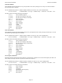
SYSTEM COMMAND TABLE................................................................................150
SECTION 22
FACTORY DEFAULTS ............................................................................................157
DEFAULT USER COMMANDS .................................................................................................................................... 157
DEFAULT MACRO DATA ............................................................................................................................................ 158
Page vi
Pacific Research Solutions
RI-300e User Manual
SECTION 1
INTRODUCTION
What is the RI-300(e) Version
The RI-300e and RI-310e are revised versions of the RI-300 and RI-310. The RI-300e has some enhanced performance
features, including a battery backed real time clock (RTC). This manual will cover both controllers. Areas where there are
differences between the controllers will be clearly pointed out. However, when this manual talks about the controller as
“RI-300” or “RI-310” it is also including the “e” version.
Overview
Your controller represents the latest technological advances in repeater control systems. The RI-300 utilizes a microprocessor
design, which provides all the control functions for a single repeater on two printed circuit boards, each 3½ by 6 inches. One
board provides all audio processing and the second board provides for digital processing. With this two-board design, the
digital data is isolated from the audio to produce superior audio quality. The RI-300 does not require memory backup batteries;
all program configurations are stored in a NON-VOLATILE EEPROM (Electrically Erasable Programmable Read Only
Memory), which maintains its data even with the power disconnected. This EEPROM may be re-programmed by the user in
order to change the system characteristics. A “WATCHDOG TIMER” and “POWER SUPPLY SUPERVISORY CIRCUIT”
constantly monitor the microprocessor and power supply, maintaining the operational integrity of the system.
The RI-300 is easy to set up and use. Only five interconnect wires are required to interface to your repeater. With three simple
audio level adjustments, your repeater will be operational with the default user commands. The telephone is connected with the
provided RJ-11 telephone jack.
Once you are familiar with the macro command system, you can customize your user commands, messages, and schedulers.
We recommend that you read sections 1 through 3, 8 and 9 of this manual first, to get familiar with the system and its basic
operation. The other sections of this manual provide a more thorough explanation of the RI-300's many features.
Feature List
The following features of the RI-300 repeater interconnect are not available together in any other repeater controller in the
industry:
•
•
•
•
•
•
•
•
•
•
•
•
•
•
•
•
•
•
•
•
•
On board CTCSS and DCS decoder and encoder. You do not have to add an external decoder. The decoder and encoder
are remotely programmable. Multiple CTCSS and DCS tone panel features are provided.
Full duplex telephone interface with a self-balancing hybrid.
Speech synthesizer. Read back system configuration and create your own speech messages. Includes a 661-word
vocabulary and 32 command words (example Time, Temperature, etc.).
Optional digital voice recorder. Create your own messages or station identification in your own voice.
Flash program memory. You can make firmware updates without changing any components.
Local microphone and speaker connections.
Auxiliary audio buss. Connect as many as 8 controllers for links, remotes and multiple repeater connections.
The Transmit audio level, squelch level, tone generator level, CTCSS level, DCS level and telephone level potentiometer
adjustments may be remotely adjusted by radio.
On board squelch circuit. You do not have to add someone else’s circuit. This is SmartSquelch, an intelligent
microprocessor-controlled squelch already installed on board, and it’s fast.
A selectable sub audio reject filter is provided to remove the received CTCSS sub-audio tone from being repeated.
DTMF tones may be passed, muted, or regenerated.
Dual tone generator with level and frequency control is available.
In-band frequency counter.
Temperature sensor input
Analog input for S-Meter or other analog devices.
User programmable inputs and outputs.
User programmable event scheduler. Commands can be programmed to execute automatically at user-selected times.
Built-in receiver audio level meter. You do not need a voltmeter or scope to set up the receiver audio level.
NON-VOLATILE EEPROM data storage. You never have to be concerned with replacement of the memory backup
battery.
User command macro editor. All user commands are completely programmable.
All the repeater owner has to do is interface the repeater audio and remotely program the functions and features desired.
Page 1
Pacific Research Solutions
RI-300e User Manual
The RI-300 provides excellent audio quality. With proper consideration when interfacing the controller to the receiver and
transmitter, your repeater will provide excellent audio to the users. Interfacing information is provided in numerous sections of
this manual and support is available from the factory. The receiver discriminator output must be connected to the RI-300 audio
input in order for the squelch circuit to function properly and to provide excellent audio. Do not connect the RI-300 audio
input to the receiver speaker connection, as the squelch will not operate properly. The RI-300 provides for easy
programming of customized user features or user commands by giving you the ability to write and name simple macros. All
messages and telemetry are also programmable.
For the latest product documentation updates and information, visit our web site at “http://www.pacres.com”.
What is an RI-310?
The RI-310 is one model in a series of RI-300 repeater controllers designed specifically as a “Plug-N-Play” component for the
Yaesu/Vertex VXR-5000 repeaters. This manual was written around the RI-300 repeater controller, which is a generic version
that is designed to interface with any repeater. The RI-310 has some additional features that allow you to remotely control the
frequency and transmit power level of the repeater.
Page 2
Pacific Research Solutions
RI-300e User Manual
SECTION 2
QUICK START
This section will cover the basics of installation and programming of your RI-300. You may also need to review section 4 or 5
for more details on connecting your RI-300 to your repeater. Once you have covered these basics, we recommend that you
thoroughly review the complete manual in order to get the most out of your controller.
UNPACKING THE RI-300
Inspect the carton for the following contents and if any of the items that you have ordered are missing or damaged, notify your
RI-300 dealer or the factory that shipped the unit to you.
1.
2.
3.
RI-300 Repeater controller board with mating DB15S connector. RI-310 does not come with the DB15S connector.
UM-300 Printed user manual.
Optional accessories that may be included with your RI-300.
MOUNTING THE RI-300 REPEATER CONTROLLER
Skip to section 5 if you are installing a RI-310
1.
2.
An optional single controller desktop chassis or a standard 19-inch wide 1-3/4 inch high rack mounted enclosure is
available. Mounting holes are provided for the repeater controller boards within the enclosure.
The repeater builder can mount the RI-300 repeater controller in any enclosure of his choice. The enclosure that you select
should be strong enough to mechanically protect the contents. The enclosure should be made of metal with good shielding
properties. We do not recommend the use of a plastic enclosure in a RF environment. Mount the RI-300 unit with #4-40
standoffs on the mounting surface.
3. Avoid installing the RI-300 in the following places:
• Directly above a transmitter or power amplifier because of heat and RF considerations.
• Directly above any power supplies because of heat and 60 Hz coupling into the audio circuits.
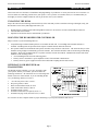
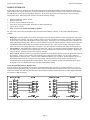
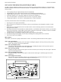
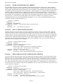
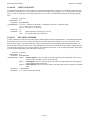
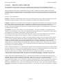
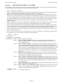
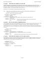
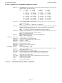
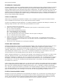
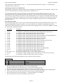
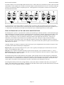
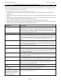
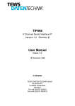
INTERFACE YOUR RECEIVER and
TRANSMITTER
The RI-300 repeater controller is very easy to interface with
your repeater. Before you continue, you need to make the
following connections. All connections are covered with greater
details in section 4 of this manual. If you are installing the RI310, you should go directly to section 5.
1.
2.
3.
4.
5.
6.
7.
386+ 72 7$/.
7;02'8/$7,21
5;',6&5,0,1$725
9'& 32:(5
$1$/2* ,1387
',*,7$/ ,1387 ',*,7$/ ,1387 ',*,7$/ ,1387 +12 Volts DC power source, J1 Pin 1.
DC power ground, J1 Pin 9
Receiver Discriminator audio, J1 Pin 2.
Audio return and/or shield, J1 Pin 10.
Transmitter audio, J1 Pin3
Transmitter DCS audio (if required), J1 Pin 11.
Transmitter keying circuit (PTT) active low, J1 Pin 4.
32:(5 *5281'
$8',2*5281'
7;'&6
',*,7$/ 287387 ',*,7$/ 287387 ',*,7$/ 287387 ',*,7$/ *5281'
5DGLR ,QWHUIDFH &RQQHFWRU
See section 4 for more complete details on proper interfacing to your repeater transmitter and receiver.
Page 3
Pacific Research Solutions
RI-300e User Manual
SETTING AUDIO LEVELS
Adjusting the levels in your controller is very important, in order to achieve proper decoder operation and avoid clipping and
distortion. See section 7 of this manual for more complete details on correct adjustment of the audio levels.
Receiver Gain
1. Setting the receiver input gain maybe the most important adjustment in the controller.
2. Transmit a carrier on the repeater’s input channel.
3. Generate a 1000 Hz tone at 1.5 kHz of deviation on the repeater input.
4. While you are sending your test tone, press and hold the button labeled “INIT”. The system LEDs will operate as a level
meter, the first LEDs through “AUX” will indicate 1.5 kHz of deviation.
5. The receiver input level is adjusted by the multi turn pot VR1 labeled “RCVR” located right of the radio interface
connector.
Squelch Level
The RI-300 uses a digital potentiometer for the squelch level setting. Unlock the controller and use S-Command 50 to set the
squelch potentiometer to specific steps or allow up and down control of the potentiometer. You can also use the programming
software to adjust this potentiometer. Set the squelch level until the COS LED goes out, and then add about 4 to 5 counts to the
setting.
Transmitter Level
The best method is to use a service monitor to measure the transmitter deviation. If a service monitor is not available, use any
receiver that can be easily flipped back and forth between the repeater input and output channel while listening to the levels.
Ideally, you will have the same transmit deviation going out of the repeater transmitter as coming in the receiver. Transmit a
3kHz deviation tone on the repeater input channel. As you flip back and forth between the repeater input and output
frequencies, then by listening, adjust the repeater transmitter audio level or deviation. This level is remotely adjusted with a
digital pot, S-Command 12. You can also use the programming software to set the transmitter level potentiometer.
OPERATION
Once you have connected your controller to a receiver / transmitter and adjusted the audio, you should then confirm its basic
repeater operation. This can be done by transmitting a carrier in the input of the repeater and observing the “COS” LED
turning on and off when you key and un-key. You should next see the “PTT” LED turn on while the repeater transmitter is on.
Next, you can confirm the repeater audio path by listening to your self on the output of the repeater. Finally, if you transmit a
carrier with a 100Hz CTCSS tone on the input of the repeater, you should see the “RPT-TSQ” LED go on and some other
LED’s flashing. The flashing LEDs will be described later in this section. See section 8 of this manual for more details on the
controller’s operation and default user commands.
INITIAL SETTINGS
You are now ready to set the Station ID and Tone Squelch (CTCSS) decode. This subject is not easily covered in a single
paragraph. Therefore, we recommend that you go to section 9 of this user manual for this procedure.
Page 4
Pacific Research Solutions
RI-300e User Manual
SECTION 3
PROGRAMMING SOFTWARE
An optional programming software and cable package is available. This software is designed to run in Windows 95/98, ME,
NT, 2000 and XP. The software will allow you to read, change and save all parameters within your RI-300 controller. You can
even load controller firmware update (FLASH) to the controller over the programming port. For software installation, follow
the instructions included with the software disk. The supplied programming cable is a special cable and has interface
electronics built in. Do not try to build your own cable. You can plug this cable into the controller at any time with or without
the controller powered on. Use the connector labeled “MIC/PROG”. Do not try to plug this cable into the connector labeled
“TELCO”. The end of the cable with the D-Sub connector, plugs directly into your computer’s COMM port. Make sure the
power to the repeater and controller is turned on. The auxiliary buss will be disabled during the data transfer process when you
are sending or receiving data using the programming software.
You may us the Pacific Research ProgramLink or the Vertex VX-VLP-1 cable with the programming software to program you
controller.
INSTALLATION
1.
2.
3.
4.
Install this program in a Windows 95, 98, ME, NT, 2000 and XP based environment.
From your floppy disk or CD ROM, run the setup program.
Follow the instructions from the setup program.
You can now click the RI-300 icon to start the programming software.
OPERATION
1.
2.
3.
4.
5.
6.
7.
8.
9.
After you have installed your repeater controller, attach the programming cable to the programming port on the controller.
Connect the other end of the cable to your PC serial communication port.
Start the programming software.
Select the "Serial Comm. Port" you are using.
You should notice that the "Active Controller" LED is lit. This means that the programming software is communicating
with your controller. You may select an active controller for viewing or communicating at any time. Do this by clicking
on an active controller LED or via the “View Controller” combo list. If none of the Active Controller LEDs show
indication of a controller, check your Comm. Port number and the programming cable.
Before you send any data to your controller the first time, you need to make a template of your controller.
Go to "Controller" and "Get data from…" pick the "Start Button". This upload process will take about 90 seconds. You
should notice the progress bar moving during this process.
Once this process is complete, select "File" and "Save As". Select the file or type "RI300.rdf", this is the startup template
file. When the program asks if you want to replace this file, pick yes.
Each time you start the programming software, the program will automatically load and start with the RI300.rdf file. Now
each time you start the programming software, it will start with the defaults from your controller.
At any time, you can save your working data to a new file name.
When making changes to your controllers data, it is good practice to save the repeater data file (rdf) with a dash number each
time you make a change. This way, you can return to an older file that you know works if you make an error in your current
file.
FLASHING the CONTROLLER’S PROGRAM
As new features are added and revisions are made to the RI-300e, program updates are made available on our web site
www.pacres.com. You can locate these changes under the RI-300e firmware and software page. Do not attempt to flash a
RI-300e controller with RI-300 version 1.xx or 2.xx firmware. Only flash using version 3.00 or higher. With the same note, do
not attempt to flash a RI-300 controller with a version 3 or higher. Download these files from the web site and follow the install
instructions. It is important to closely follow the instructions as you may otherwise damage your current installation. Once you
have down loaded these updates, use the following procedure to flash the controllers program memory.
1.
2.
3.
4.
Connect your computer to the controller using the programming cable. Run the RI-300 Programming.
In the programming software, pick “Controller” then pick “Flash Program”.
In the file list, select the new flash file you want to send to the controller. The last three digits of the file name indicate the
file version.
Pick the “Open” button then the “Start” button. The flash process is automatic and will take 90 to 120 seconds to
complete.
Page 5
Pacific Research Solutions
RI-300e User Manual
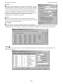
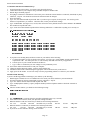
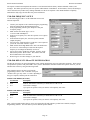
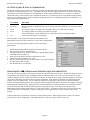
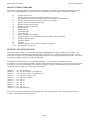
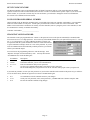
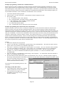
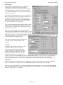
PROGRAMMING SOFTWARE MENU
The basic startup window contains the status items shown. Use the "View Controller" or pick the “Active Controller” light to
select which controller on the auxiliary buss you want to monitor. Whenever you leave the cursor on a window item, the
program will show a hint as to the associated System Command that is adjusted by that item. The following is a quick overview
of menus and their functions.
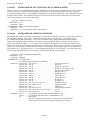
Main Window
The main window shows the current activity of a selected
controller on the buss. The “Active Controller” group
displays all active controllers attached to the auxiliary
buss. The “Controller x Status” group shows the status of
the selected controller. The “Auxiliary Buss” group
shows the auxiliary buss status of the selected controller.
All System Commands sent over the auxiliary buss are
also logged within this group. The “RX Deviation” group
is used to set up the controller’s receivers input level.
This gauge is only active when you press the “INIT”
button on the controller after the power is turned on. The
“DTMF Decode String” shows and records the last 50
user and system commands. Each command has a date
and time stamp with the tone squelch that was used during
the command. The “Macro Error Log” will display errors
in macros as reported from the controller. If an error is
encountered when the controller executes a macro, the
controller will report the location of the error to the
programming software. You can select an error and pick
the “Show Me” button to see the location of the error in
your rdf file.
File
Used to both save and open repeater data files (rdf). The programming software uses the RI300.rdf file as a template file. Any
changes you make to this file will be recalled each time that you run the program. Report printing is also available from this
menu. In the report printing, you can select various items that you want to print. If you select all items for printing on a factory
default set up, up to a 20 page report will be generated.
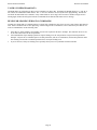
You can use the “Project Manager” to set up multiple files for applications
where you have multiple controllers connected to the auxiliary buss. In this
window, you select each rdf file for each controller that will be included in the
system. In the future, you can open this System Project File (spf) and the
software will load all rdf files used in you system. You can now select which
rdf file you want to edit using the “View Controller” or “Active Controller”
method.
Page 6
Pacific Research Solutions
RI-300e User Manual
Controller
This menu is used to send data to and get data from the controller. You may
also flash the program firmware to the controller. Any one of these functions
may take as long as 3 minutes to complete. Do not interrupt the process once
it is started. The repeater controller is allowed to be in use during the time
that you are sending data to or getting data from the repeater. These data
functions can be performed while the repeater is in use. You will also find a
modem connect sub window here. This connection may be used to
communicate to your controller via a modem.
Repeater
This menu is used to adjust the repeater, squelch, auxiliary and frequency
functions. Each sub windows will have a "SEND" button you can use to send
only that window's data to the controller.
Tone Squelch
This menu is used to set up the CTCSS/DCS decode and encode function.
You can also find a CTCSS/DCS Air Time sub window. This window will display the airtime for each CTCSS/DCS decode,
including ones that you are not using. You must do a “Get Data From Controller” before air times will be correctly shown.
Commands
This menu is used to set up all types of user commands and allow the editing of macro data. See the following section for
details on macro editing.
Page 7
Pacific Research Solutions
RI-300e User Manual
Triggers
This menu is used to set up messages, various internal event triggers and the scheduler.
Telephone
This menu is used to set up the telephone operation, access/account codes, auto dial numbers and toll restriction.
Help
Use this menu to get help on any of the programming software items.
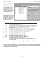
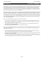
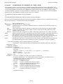
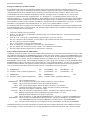
MACRO EDITING MENU
You can edit the macros associated
with commands by clicking the
“Edit Macro” button in any of the
user command menus. In the “Edit
Macro Data” sub window, you can
pick various macro lines and
display the decoded macro data.
You can also pick the “Macro
Source” tab to display all user
commands, event triggers, calls and
jumps that reference that macro.
When editing the macro data, you
can right click the “Edit System
Commands” box to get a System
Command from a list. You can
also right click the “Line No” box
to get a view of the macro data
when looking for an empty line to
build your macro. On the left side
of the macro decode window, you
can drag and drop any System
Command to change the order of
the System Commands in the
macro. Finally, you can add a
description to your macro. It should
be noted that the description data is
only saved to the .rdf file only and
not saved to the controller.
The structure and syntax used to
build any macro or message is the
same structure you would use over
the air with DTMF. Just as in
building a macro over the air, you
must include a “64” at the end of all
macros to terminate the macro.
Similar to building a macro over the
air, the software will keep track of
the total number of digits and lines
used in a macro. Various errors are
also displayed in this window.
Page 8
Pacific Research Solutions
RI-300e User Manual
MODEM INTERFACE
You should be able to use about any external modem that operates at 9600 baud or higher, can auto answer and operate in a
dumb terminal mode. In this application, we used a US Robotics external modem to connect to the controller. On the back of
the USR modem, you will find a configuration dipswitch. Set all of the dipswitches in the up position, except for switch 4,
which will be down. When using other modems, consider the following settings:
•
•
•
•
•
•
Data Terminal Ready (DTR) - normal
Suppress result code
No echo, off line commands (Echo Off)
Auto answer on first ring or higher, depending on shared telephone line
Carrier detect - normal
Dumb terminal mode, disable command recognition
For people who want to share the telephone line between the modem and the controller, we have three different methods
available:
1.
2.
3.
Ring Delay: With this method, you connect the telephone line to the modem and then connect the phone jack output from
the modem to the controller. Set up the modem to answer on 2 more rings then the controller. Example: set the controller
to answer after 2 rings and set the modem to answer after 4 rings. Then create a user command that sets S-Command 71 to
mode 0, disabling incoming calls. When you want to establish a connection with the controller’s modem, execute the user
command and then call the modem, the controller will not answer the call. Once you are finished or during the modem
connection, reset the incoming call mode to 2 or higher. Now, the controller will answer calls before the modem answers.
Call switch box: This method uses a modem/voice switch box. This is a box that into which the telephone line plugs. The
box modem port is connected to the modem and the box voice telephone port is connected to the controller. When a call
comes in, the box will direct the call to the modem or controller.
Power control: With this method, you connect the telephone line to the modem and then connect the phone jack output to
the controller. Connect a relay so that it will switch the power supply line of the modem. Use one of the controller’s
digital outputs to control the relay. Create two user commands to turn the relay on and off. Set the modem to answer on
the first ring and the controller to answer on 2 or more rings. When you want to call the modem, execute the user
command to power the modem and then call the modem. Once you are finished, send the user command to power down
the modem. Now the controller will answer the calls and the modem will not.
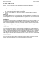
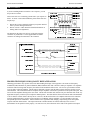
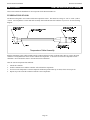
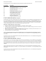
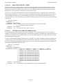
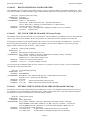
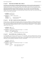
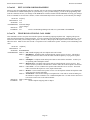
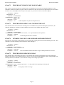
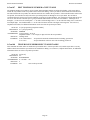
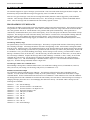
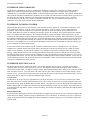
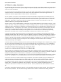
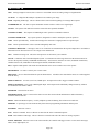
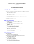
Vertex Programming Cable to Modem Cable
If you are using the PL-3 ProgramLink, you can use a standard modem cable to connect your modem to the PL-3. If you are
using the Vertex programming cable, you need to build a modem-to-modem cable because the Vertex cable works in the same
manner as a modem. The following schematic shows how to build a modem-to-modem cable for a modem equipped with DB25 connector or DB-09 connector.
352*5$0 &$%/(
02'(0
352*5$0 &$%/(
02'(0
5;'
7;'
5;'
7;'
7;'
5;'
7;'
5;'
'75
'65
'75
'65
*1'
*1'
*1'
*1'
'65
'75
'65
'75
576
&76
576
&76
&76
576
&76
576
'%3
'%3
'%3
'%6
&211(&725 0$/(
&211(&725 0$/(
&211(&725 0$/(
&211(&725 )(0$/(
Page 9
Pacific Research Solutions
RI-300e User Manual
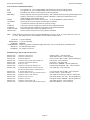
U.S. Robotics 56K External Modem Set Up
1. Set the dipswitch on the modem. Set switch 3 and 8 down all others up.
2. Connect the modem to your computer using a standard computer-to-modem cable.
3. Run the Hyper Terminal program.
4. Set up Hyper Terminal to communicate to the comm. port to which the external modem is connected, 9600 baud, no parity,
8 data bits, 1 stop bit. The baud rate used must be 9600 and cannot be changed.
5. Power the modem.
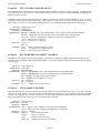
6. Type “AT”, the modem should respond with “OK” if you do not get a response, do not proceed. You need to get the
modem to respond before you continue. Check the cable, comm. port and switch settings.
7. Type “AT&F1&W0” (last digit is zero, not oh). This restores the factory defaults and saves these defaults to the EPROM.
The modem will respond with “OK”
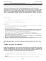
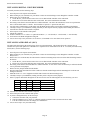
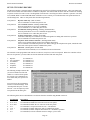
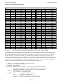
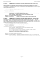
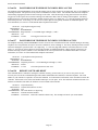
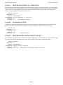
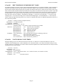
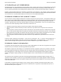
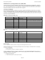
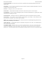
8. Type “ATI4” the modem should respond with the following information. Confirm that everything is set correctly set.
86 5RERWLFV . )$; (;7 6HWWLQJV
% ( ) 0 4 9 ; <
%$8' 3$5,7< 1 :25'/(1 ',$/ 721(
21 +22. &,' $ % & ' * + , .
0 1 3 5 6 7 8 <
6
6
6
6
6
6
6
6
6
6
6
6
6
6
6
6
6
6
6
6
6
6
6
6
6
6
6
6
6
6
6
6
6
6
6
6
6
/$67 ',$/(' 9.
10.
11.
12.
13.
If you plan to use the Ring Delay method to connect to your modem, do the following
a. To change the number of rings on which to auto answer, to 4 rings, type “ATS0=4&W0” and the modem should
respond with “OK”. You can replace the “4” value with any value that will work for you application.
b. Turn the power to your external modem off and then on
c. Type “ATI4” to confirm that your new settings are now permanently saved.
Turn off the modem and disconnect it from your computer.
Change the modem dipswitch settings: (switch 4 down all others up).
Attach the modem to the controller using the appropriate cable as discussed early in this section.
Apply power to the modem. You are now ready to use the programming software to connect to your controller.
Modem Trouble Shooting
If you are still having problems connecting to your modem, try the following:
1. Restart Hyper Terminal, but set it to communicate to the comm. port that is attached to your internal mode.
2. Set Hyper Terminal to connect at 9600 baud, no parity, 8 data bits, 1 stop bit.
3. Type “AT” and the internal modem should respond with “OK”.
4. Type “ATD[telephone number]”, replace [telephone number] with the telephone number to which the controller is
connected.
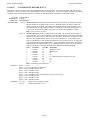
After the modem connects, you should see the following message:
&211(&7 $549/$30
!&**!&**-
The “!&**-µ is a message from the controller and should repeat every 2 seconds.
If the modem will not answer, check your dipswitch settings and cables.
When the modem is idle (not connected) you should see the following LED status:
AA = ON
CD=OFF
RD=OFF
SD=Flash every 2 seconds
TR=ON
CS=ON
9. When the modem is connected you should see the following LED status:
AA = ON
CD=ON
RD=OFF
SD=Flash every 2 seconds
TR=ON
CS=ON
10. If you do not see the controller message, check all cables.
6.
7.
8.
Page 10
ARQ=OFF
ARQ=ON
Pacific Research Solutions
RI-300e User Manual
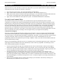
SECTION 4
INSTALLATION (RI-300)
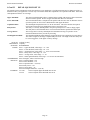
If you are installing the RI-310 into the Vertex repeater, you can
skip to the next section.
This section will cover connecting your RI-300 to your repeater in
detail. To ensure a successful installation, please follow these few
simple steps.
1.
2.
Review this section completely and plan you repeater interface
before you start making connections.
Review section 7 of this manual for detailed information on
making audio level adjustments.
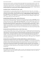
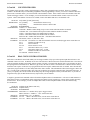
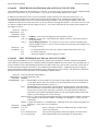
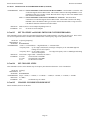
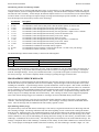
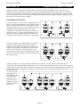
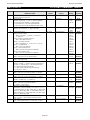
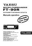
The diagram on the right is an end view of the radio interface
connector on your RI-300. Use the supplied DB-15S female
connector for making all connections to the controller.
386+ 72 7$/.
7;02'8/$7,21
5;',6&5,0,1$725
9'& 32:(5
$1$/2* ,1387
',*,7$/ ,1387 ',*,7$/ ,1387 ',*,7$/ ,1387 ',*,7$/ 287387 ',*,7$/ 287387 ',*,7$/ 287387 ',*,7$/ *5281'
32:(5 *5281'
$8',2*5281'
7;'&6
5DGLR ,QWHUIDFH &RQQHFWRU
5, 5HSHDWHU &RQWUROOHU
5(3($7(5
5HFHLYHU
5;'LVFULPLQDWRU ,Q 'LVFULPLQDWRU 2XW
*QG
$XGLR *URXQG 6+,(/'
$PS )XVH
9ROW 6XSSO\ 2XWSXW
9'& 3RZHU ,QSXW 6XSSO\ 5HWXUQ
3RZHU *URXQG 7UDQVPLWWHU
7;0RGXODWRU 0RGXODWRU ,Q
*QG
3XVK 7R 7DON 7; .H\ 377
5HSHDWHU &RQQHFWLRQV
PROPER TECHNIQUES FOR QUALITY REPEATER AUDIO
Obtaining good audio in any repeater is based on understanding the design of the equipment. The audio in all frequency
modulation (FM) transmitters or phase modulation (PM) transmitters has what is known as audio pre-emphasis. Pre-emphasis
means that with increasing audio frequency the amount of the modulation will increase. The reverse is performed in all FM
receivers and is called de-emphasis. The RI-300 was designed to operate with flat audio response from the repeater receiver
and transmitter. This means that neither de-emphasis nor pre-emphasis of the audio is performed on the repeat audio path. This
leaves all of the emphasis filtering in the user's radio. The RI-300 controller does include a low pass filter that rolls off the very
high audio frequency content to prevent adjacent channel splatter. The ideal interface between the RI-300 and a FM modulator
is one in which a varactor diode is directly driven. However, the RI-300 does have a de-emphasis filter that can be turned on
for those applications where you may need to interface to a modulator with pre-emphasis. It is not advisable to drive the
microphone input on the transmitters. Most transmitters have significant audio shaping, compensating for the microphone
response and other characteristics. The input connections to the RI-300 must be connected directly to the receiver’s
discriminator for the squelch to work properly. On some receivers, this connection can be made to the squelch circuit input.
Page 11
Pacific Research Solutions
RI-300e User Manual
Besides audio frequency response, you should consider the audio amplitude levels to and from the controller. If the levels to
and from the repeater are small, it may be valuable to use shielded cable. We recommend shielded cables at all times. Use
large signal levels whenever possible. On the other hand, do not let the audio signal get large enough where clipping occurs in
any stage of the controller, the receiver, or the transmitter. The RI-300 repeater controller has a built in audio level meter for
setting the RX input level. See section 7 for more details on adjusting the audio levels in the controller. Consider and practice
the above and you will have repeater audio that you and your repeater users will be proud of.
POWER SUPPLY CONNECTIONS (Pins 1 and 9)
The RI-300 operates on 12 volts DC nominal. The DC source voltage must be between 10 and 15 VDC. The controller
typically draws 140 ma. without the status LEDs turned on. Connect the +12v to J1 pin 1. Connect J1 pin 9 to ground or the 12
V return side of the power supply. The repeater builder may elect to incorporate an on/off power switch on the +DC side.
Most repeater owners switch the AC primary side of the power supply. The RI-300 repeater controller connection to the
power supply must be over-current protected. Use of a one-ampere fuse should be the largest capacity considered in your
installation. A ½ amp fuse is best. When connected properly, the green LED on the status LED display will light when the
power is applied and the system enable command is on.
REPEATER RECEIVER AUDIO CONNECTION (Pin 2)
Since the RI-300 controller has the squelch (COR/COS) circuit incorporated on board, the audio input MUST BE connected
directly to the receiver discriminator output. Connect the receiver discriminator audio to the RI-300 J1 pin 2 and the receiver
ground or audio return to J1 pin 10. Do not connect to the speaker leads. If you are not familiar with the repeater receiver,
get assistance from someone knowledgeable on the subject or contact our factory for support. If your discriminator does not
have adequate filtering for 455 kHz, you will have to provide for this filtering between the radio and controller. A 10mH
inductor in line with a 1000pF capacitor to ground should work. You may need to adjust these values according to the output
impedance of your discriminator. For best performance all audio connections should be made with a shielded cable. The
controller’s audio path has a flat frequency response from 30 Hz through 4500 Hz except for the CTCSS high pass filter that
cuts off at 300 Hz. When interfaced properly to the repeater receiver and transmitter, the controller will provide superb audio
characteristics.
REPEATER TRANSMITTER AUDIO CONNECTIONS (Pin 3)
Use a direct FM type modulator whenever possible. The RI-300 does have a de-emphasis filter that can be turned on for those
applications in which you need to interface to a modulator with pre-emphasis. It is not advisable to drive the microphone input
on the transmitters. Most microphone inputs have significant audio shaping, compensating for the microphone response and
other characteristics. Always use a shielded cable. Connect the controller transmit audio output J1 pin 3 to the input of the
modulator. Connect the modulator ground or audio return to J1 pin 10. If a FM modulator without pre-emphasis is not
available, the RI-300 can be jumped to drive a phase modulator or modulator with pre-emphasis. Do this by installing jumpers
on JP5 pins 1-2 and JP1 pins 1-2. For FM modulation, install a jumper on JP5 pins 2-3 and no jumper on JP1. See section 17
for more information on this subject.
REPEATER TRANSMITTER PTT OR TRANSMIT KEYING CONNECTION (Pin 4)
The RI-300 repeater controller keys the transmitter at the required times. WARNING - As with all repeater controllers, this
controller will key the transmitter at times you may not think of, such as when the ID is due. It never fails when you disconnect
the antenna to connect an in-line wattmeter, the ID goes off or a repeater user arrives on the receiver input. Therefore,
disconnect power to the repeater and controller before performing these operations. The controller PTT keying transistor sinks
current, that is, the transistor pulls to ground the relay or keying stage in the repeater transmitter. This is by far the most
common interface. Should you need to source a voltage to PTT then contact Pacific Research Solutions for application notes.
The keying transistor can sink or pull down (active low) a maximum of 120 ma of current. Connect J1 pin 4 to the repeater
transmitter PTT.
DCS MODULATION (Pin 11)
Some transmitters will not accept DCS modulation with the voice audio. In these applications, the RI-300 will output the DCS
modulation on this pin so that it can be directly connected to the DCS input on your transmitter. Please review section 7 for
additional information on this subject.
Page 12
Pacific Research Solutions
RI-300e User Manual
DIGITAL INPUTS (Pins 6, 7 and 8)
The RI-300 has three digital inputs on board and is currently expandable up to ten, that can be used to trigger macros. These
inputs are C-MOS gates with a voltage swing of 0 to 5 VDC, TTL level. All digital inputs have a 10K ohm pull up resistors.
Your application must “pull down” or sink current with either a transistor or TTL gate or equivalent. Upon detecting either a
rising or falling edge or change in the state of an input, the controller automatically executes a macro. See Section 12,
S-Command 45 and 46 for additional information on programming these inputs. These inputs are located on J1 pins 6, 7 and 8.
See the connector diagram on the previous page. Depending on the squelch mode, S-Command 51, input bit 1 can be used as
an external squelch input.
DIGITAL OUTPUTS (Pins 13, 14 and 15)
The RI-300 has three digital outputs on board and is currently expandable upto ten, whose states can be modified by
S-Commands. Each of the three outputs can be individually commanded or forced into the high or low logic state or pulsed
high for a desired duration of time. These outputs are open collector NPN transistors and can sink up to 120ma each. Each
output has a 10K pull up resistor to 5 volts and can source enough current to drive a TTL or CMOS gate. However these
outputs can sink current from a voltage sources as high as 24 volts. Using S-Commands (or macros that are composed of SCommands), each output may be turned on or off or pulsed with the desired S-Commands. See Sections 12 S-Command 46 and
47 for additional information on programming these outputs. These outputs are located on J1 pins 13, 14 and 15. See the
connector diagram on the previous page.
ANALOG INPUTS (Pin 5)
The RI-300 has one analog input that can be directly read as a voltage in the range of 0 to 3.75 volts. This input can also be
connected to your radio's limiter output for a Signal Meter function. In some S-Meter applications, you may need to provide a
method for scaling the voltage connected to this input. When reading this signal over the air, use speech control word 014 for
the analog voltage and speech control word 013 for S-Meter.
DCS DECODE AND ENCODE SET UP AND OPERATION
With DCS (Digital Coded Squelch) decode and encode, you can also select any combination of DCS codes to operate your
repeater. You have 104 standard DCS codes that can be used for decode or encode. The decode codes are selected with
S-Command 20. The encode codes are selected with S-Command 21 and 22. Both CTCSS and DCS will operate together.
The system set up for DCS is the same as CTCSS.
Depending on your repeater, you may have to change the polarity of the DCS TX/RX data. Once you have confirmed that your
radio audio frequency response is correct, you can enable a DCS code for the repeater decode (S-Command 20). When you
send that code to the repeater, check if the CTCSS/DCS LED goes on. If the controller does not decode DCS data, change the
RX polarity (S-Command 25). If your radio will not decode the DCS data from the repeater, change the TX polarity (SCommand 25). You can also use the programming software to view the current DCS decode to verify the data polarity.
The DCS encode level is remotely adjusted with a digital pot in the same manner as the squelch, except with S-Command 24.
The DCS encoder audio can be mixed with the voice audio or routed directly to the transmitter modulator via J1 pin 11. As
some modulators require a separate input for DCS audio.
CTCSS (Continuous Tone Coded Squelch System) uses continuous tones below 300 Hz. A single tone is assigned for a group
of users. When the tone has been decoded by the repeater, the repeater will pass the users audio. Sometimes two tones next to
each other can become confused with each other. In contrast, DCS uses digital data or code words. Each code word is unique
and all code words may be used on the same channel without interference. At the end of the repeater transmission and 1/2
second before the transmitter un-keys, the controller will encode a 134 Hz tone that serves as a turn off code. For correct
operation, the DCS data should have a FM deviation of 500 to 800 Hz.
Your transmitter and receiver waveforms should closely
resemble the waveform diagram, figure 1. If this is the
condition, then the low frequency response of your
repeater should be adequate. If your waveform resembles
figure 2, your modulator or discriminator does not have
enough low frequency response. Figure 2 was created
with a high pass filter with a corner frequency at about 5
Hz. Even with a cutoff this low, the filter strips vital data
from the digital code word.
)LJXUH Page 13
)LJXUH Pacific Research Solutions
RI-300e User Manual
Because DCS may have extended periods of all ones and zeros, almost all components in the transmitter and receiver chain
must be coupled down to at least 2 Hz or lower. This requirement means that certain transmitters and receivers must be
modified before they are capable of DCS operation. Phase modulators, in particular, need special consideration because they
theoretically are incapable of being directly modulated by DC, unlike direct FM modulation methods. Low frequency response
is the primary requirement for DCS systems.
Unlike CTCSS, DCS the signal spectrum occupies considerable more bandwidth. A poor low frequency response in the
transmitter or receiver may not seriously distort a single frequency tone signal but may seriously degrade a wide band signal
containing multiple frequency components. The distortion risk is especially high if the frequency response delays the wide
band frequency components.
The RI-300 does include data error correction. But if too many errors occur, you may experience some blocking out of the
decoder. Errors can occur because of unwanted low frequency energy. The DCS decoders can be affected by voice energy that
falls below 300 Hz. Some radios do not remove this energy before transmission and can cause voice blocking of the decoder.
The RI-300 has a sub audio filter that removes this low frequency energy before the audio is re-transmitted. This feature will
increase the performance of the receiving radios. You may need to confirm that the radios used to operate the repeater, have
some type of sub audio filtering.
You will find that it is extremely important for the receiver and transmitter to be on frequency to achieve maximum
performance of the DCS function. Errors in the transmitter and receiver frequencies show up at the discriminator output as a
step function. Because of the long time constant required for the low frequency response, a step function can block the decoder
momentarily.
Before you start modifying your radio to operate DCS, make sure your service monitor is DCS capable. Some older monitors
require modifications to obtain the low frequency audio response needed for DCS operation. If in doubt, contact the
manufacturer.
Because there are so many radios that may need modification for DCS operation, we may not be familiar with your radio. For
this reason, we may not be able to provide technical support for some radio modifications. We want to hear constructive and
useful feedback. We appreciate having details about your successful modification of a radio for DCS operation.
Page 14
Pacific Research Solutions
RI-300e User Manual
SECTION 5
INSTALLATION (RI-310)
After unpacking and inspecting your RI-310 repeater controller, use the following steps to install the controller into the Vertex
VXR-5000 repeater.
1.
2.
3.
4.
5.
6.
7.
8.
9.
11.
12.
10.
13.
14.
15.
16.
17.
18.
19.
20.
21.
22.
23.
24.
Before starting, locate the serial number of your controller on the backside of the PC Board. It is important to make
note of this number in a safe place. This number can be used with S-Command 58 or 59 to remotely reset or reinitialize the program.
Start by removing the four screws holding the top cover on the Vertex repeater.
Position the repeater with the antenna connector toward you and the heat sink to your right. The receiver unit is the
box closest to the “RX ANT” connector. The transmit unit is the box on the other left side far end of the chassis.
The RI-310 controller will replace the Vertex controller. Completely disconnect all cables going to the Vertex
controller. You may need to remove the Vertex controller from the chassis to get at some of the cables. When you are
finished with installing the RI-310 controller, you may leave the Vertex controller mounted in the rack, as there is
enough room for both controllers.
You will find some cables routed on the right side going toward the “ACC” and “LINE” connectors. Remove the
cable tie wraps from these cables.
In this bundle of cables, you will find a 13-conductor cable. Re-route this cable past the left side of the receiver.
You will not be using the "LINE" connector cables on the right side of the receiver unit. You can pull these cables
back to the “LINE” connector. We will also not be using the 12-conductor cable that is routed on the left side of the
receiver unit. You can also pull this cable back, bundle and tie these cables together and stow them.
Locate the 6-conductor LED cable. This cable has multi-colored wire. Plug this cable into the connector (J1013) on
the bottom of the RI-310 interface board. This cable has 6 conductors but the connector housing has 7 positions.
Find the 5-conductor cable that comes from the power supply unit. This cable has two red wires, two black wires, one
white wire and a 6-pin housing. Plug this cable into the connector (J1004) on the bottom of the RI-310 interface
board.
Place the RI-310 in the slot between the receiver and the vertex controller. The MIC/PROG jack should be located on
the side closest to the power supply or RF power amp.
The mounting holes in the RI-310 should line up with the mounting tabs in the Vertex repeater. The RI-310 is held in
place by the two screws that are supplied. The bottom of the RI-310 circuit board should line up with a card edge
bracket in the bottom of the Vertex repeater.
Locate two cables that exit the right side of the transmitter unit. Plug the 8-conductor cable with one yellow wire into
the RI-310 controller connector labeled “TX-UNIT”. Then plug the 4-conductor cable with one shielded gray wire
into the RI-310 connector labeled “TX-MOD”.
You should find one last 5-conductor cable with one black wire on the right side of the transmit unit. Plug this cable
into the RI-310 connector labeled “REG-UNIT”.
From the left side of the receiver unit, you will find two cables. Locate the 10-conductor cable with one violet wire
and plug this cable into the RI-310 connector labeled “RX-UNIT”. Then plug the 2-conductor shielded cable into the
RI-310 connector labeled “RX-DET”.
Last, from the left side of the receiver unit, you will find a 13-conductor cable with one green wire coming from the
“ACC” connector. Plug this cable into the RI-310 connector labeled “ACC”.
Re-inspect all cables very carefully. Make sure that you do not have any incorrect connections. You should have
three cables that are not connected to anything.
All input and output audio levels have been preset for the Vertex repeater. However, the receiver and transmitter
audio levels will need some final adjustments before you are completely finished. See Section 7 for details on this
procedure.
Adjust the potentiometer on the top of the VXR-5000 “TX UNIT” to mid position. This is the rough modulation level
for the DCS encode data.
Because the RI-310 controller may key up the repeater at any time. Make sure that you install a dummy load on the
“TX ANT” connector before you reconnect power to the repeater for testing.
If your repeater frequency was not programmed into the RI-310 at the factory, you will need to install the
programming cable into the RI-310’s “MIC/PROG” jack. Connect the other end to your PC.
Connect power the repeater and use your RI-300 programming software to set the RX and TX frequency of the
repeater, see VXR-5000 FREQUENCY SETUP later in this section.
Once you have the repeater on the air, you can follow the rest of the Vertex initialization procedure in this section.
This will enable the LEDs on the front panel of the repeater.
Before you are done, continue with the rest of this section set up the transmitter high and low power levels.
Although the audio levels are preset at the factory, you will need to make some final adjustments before installing your
repeater. See section 7 for detailed information on this subject
Page 15
Pacific Research Solutions
RI-300e User Manual
The repeater controller and telephone interconnect is now functional with the factory default commands, features, and
messages. This allows operation of your new repeater within minutes of installation. All the features, macros, and messages,
can be customized in your RI-310 by sending commands over the air or telephone. This manual should be completely
understood to fully enjoy all of the RI-310’s power and features.
VXR-5000 FREQUENCY SETUP
Use the following procedure to set the VXR-5000 receive and
transmit frequencies.
1.
2.
3.
4.
5.
6.
7.
8.
9.
Connect your computer to the controller using the programming
cable and run the RI-300 Programming Software.
In the programming software, pick “Repeater” then pick
“Frequency Setup”.
Make sure that the “Radio Type” is set to
“0-Vertex VXR-5000 Duplex”.
In the receive frequency box, enter the repeaters receive (input)
frequency.
In the transmit frequency box, enter the repeaters transmit
(output) frequency.
You can set the “Transmit Offset”, but the box is not required if
you set the “TX Offset” button to “Split”.
Make sure that both “High Band Limit” and “Low Band Limit”
are set to zero. This will help to assure that the repeater
frequency is not changed accidentally over the air.
You are now ready to update the controller. Pick the “Send”
button, than pick the “Start” button. The software will send
these modifications to the controller.
Do not forget to save these changes to your data file.
VXR-5000 DEFAULT LED and TX POWER MACROS
The RI-310 uses macros to control the high/low power settings during battery and over temperature operation. These macros
also update the repeater's front panel LEDs. Once you have installed the controller and have the repeater on the air, you can
initialize these macros by using the following format.
These initialize macros can also be run from the
programming software. Pick “Controller” then pick
“Send S-Cmd”, type only “6861” or “6859” depending on
the type of repeater, and then pick the send button.
Initialize VXR-5000DC (DC model)
S-Command
Description
1. 123456
Unlock the controller
2. 68 61
Send DC initialization command, you should hear an "OK" in CW
3. 69 1
Lock and save changes
4.
Cycle power to repeater so that your macros will completely take effect.
Initialize VXR-5000AC (AC model)
S-Command
Description
1. 123456
Unlock the controller
2. 68 59
Send AC initialization command, you should hear an "OK" in CW
3. 69 1
Lock and save changes
4.
Cycle power to repeater so that your macros will completely take effect.
After you have initialized these macros, open you repeater data file and perform a get data from controller, using the
Programming Software. Save this data as your new default repeater data file.
Page 16
Pacific Research Solutions
RI-300e User Manual
The following shows the default data for the above macros. If you want to change the repeater’s transmit power, you will need
to modify macros at line 50 and 53, see the following page for more information on this subject.
Start Line 050
Start Line 051
Start Line 053
Start Line 054
Start Line 055
Start Line 056
Start Line 057
Start Line 058
Start Line 059
Start Line 061
Start Line 063
Start Line 064
061C 131100C D
061C 65481001#480901C 6853C DD
061C 131200C D
061C 46110C D
061C 46111C D
061C 46121C 46130C 6850C D
061C 46120C 46130C 6851C D
061C 46121C 46130C 6853C D
660C 4509056C 4510151C 6863C D
660C 4509058C 4510153C 6863C D
4509157C 4510050C 4527154C
4527055C 661C D
Vertex Low TX Power, approximately 10 watts
Check for over temp and battery operation
Vertex High TX Power, approximately 25 watts
TX LED on
TX LED off
BATT LED on, AC LED off jump to Low power
BATT LED off, AC LED on jump to High power
BATT LED on, AC LED off jump to High power
AC init, enable input triggers and jump to start line 63
DC init, enable input triggers and jump to start line 63
Finish Vertex initialization.
Changing Transmitter Power Level on the VXR-5000
If you have enabled the above macros in your VXR-5000 and need to adjust the transmitter power level, use the following
procedure:
1.
2.
3.
4.
5.
6.
7.
Connect a wattmeter and dummy load to the VXR-5000 transmitter.
Connect your computer to the controller using the programming cable. Run the RI-300 Programming Software and open
your controller’s data file. If you do not have a data file for your controller, do a get data from the controller and save this
data as your controller’s data file.
In the programming software, pick “Repeater” then pick “Frequency Setup”.
Pick the “Force Transmitter On, 30 Seconds” button. Then adjust the “Transmit Power Level” slide bar while reading the
wattmeter for your high power setting (equal to or greater then 10 watts) and record this DAC value below.
Now adjust the “Transmit Power Level” slide bar while reading the wattmeter for a 10-watt low power setting and record
this DAC value below.
Return the “Transmit Power Level” slide bar to your high power setting, pick the “Send” button and then the “Start”
button. This will update the controller with your new high power setting.
Close the “Frequency Setup” window. Next, you will need to modify the transmitter power level macros.
TX High Power DAC Setting __________ at __________ watts (equal to or greater then 10 watts).
TX Low Power DAC Setting __________ at 10 watts.
Note: Vertex recommends NOT setting the transmitter power below 10 watts output or above 25 watts.
8.
9.
In the programming software,
pick “Commands” then pick
“Macro Data”. In the “Macro
Data” scroll box, select line
“050”, this is the VXR-5000
low power macro. Then pick
the “Edit Macro” button.
In the “Macro list data” scroll
box, double click the line with
“DAC Output 1 = 100”. You
will now see this information
in the “Edit System
Command” box. Change the
DAC value from 100 to the
low power value you recorded
above, “131n”, where “n”
equals the low power DAC
value.
Page 17
Pacific Research Solutions
RI-300e User Manual
10. Pick the “Replace” button. This should replace the old DAC S-Command with this new one.
11. Now pick the “OK” button.
12. In the “Macro Data” scroll box again, select line “053”, this is the VXR-5000 high power macro. Then pick the “Edit
Macro” button.
13. Repeat steps 8, 9 and 10 for the high power setting.
14. You are now ready to update the controller. Pick the “Send” button, than pick the “Start” button. The software will send
these macro modifications to the controller.
You are done. You have just modified two macros. You can use this same process to create user commands along with may
other features in the controller.
VXR-5000 ACCESSORY CONNECTOR “ACC”
The RI-310 used the 25-pin “ACC” connector to provide
various inputs and outputs. Only pins 1 through 13 of the 25pin connector are used. The following is a list of the
connector pins and functions.
$8',2*5281'
',*,7$/ ,1387 $8; $8',2 287
',*,7$/ 287387 ',*,7$/ ,1387 ',*,7$/ 287387 ',*,7$/ ,1387 %866 5(4
9'& 32:(5
6(5,$/ '$7$
1.
2.
3.
4.
5.
6.
7.
8.
9.
10.
11.
12.
13.
$8; $8',2 ,1387
',*,7$/ 287387 ',*,7$/ *5281'
Digital Ground ………... Chassis ground for all digital
inputs and outputs.
+12 Volts Output ……... This is a ½ amp output from
the regulated supply. Please
9;5 $&& &RQQHFWRU
use fuse protection.
Digital Input Bit 1 …….. This is a user programmable digital input. See S-Command 45 for additional information.
Digital Input Bit 2 ….…. This is a user programmable digital input. See S-Command 45 for additional information.
Audio Output …………. This is a receiver audio output and is programmable with S-Command 34. This output can be
set for either discriminator or de-emphasis audio. The audio on this output is 0dbm or
0.774Vrms for 5KHz Deviation. See section 16, “Setting Up Audio Channels” for audio
selection. You can also use this output to connect to another RI-310 audio input for a link or
remote.
Audio Input …………… This is audio input that can be routed to the transmitter and is programmed with S-Command
35. The audio on this input should not exceed 0dbm or 0.774Vrms for 5KHz Deviation.
Normally with the RI-310’s Auxiliary buss, you can select input channels to use. But, with this
input, audio in is enabled when any of the auxiliary buss channels are enabled. This input can
be set for either flat FM modulation to the transmitter or with pre-emphasis. See section 16,
“Setting Up Audio Channels” for audio selection. You can also use this input to connect to
another RI-310 audio output for a link or remote.
Audio Ground ………… Use this to connect to the shields of your audio cable.
Digital Input Bit 3 ….…. This is a user programmable digital input. See S-Command 45 for additional information. This
input will also support an active low COS input for the above audio input. See S-Command 92,
mode 7 for more information on this feature.
Dig. Out Bit 1 / DAC 2 .. This is a user programmable digital output. See S-Command 46 & 47 for additional
information. When the VXR-5000 is operated as a simplex remote base, this output bit is used
to operate a TX/RX relay. This pin can also be jumped to output the DAC #2 signal. See SCommand 13 for information on controlling this output. To make the jumper changes, you must
remove the interface board from the controller and locate the jumper marked "DIG/DAC"
Digital Output Bit 2 ….. This is a user programmable digital output. See S-Command 46 & 47 for additional
information.
Digital Output Bit 3 ….. This is a user programmable digital output. See S-Command 46 & 47 for additional
information. This output will also support an active low PTT output for the above audio output.
See S-Command 92, mode 7 for more information on this feature.
Buss Req ….…………… This signal is used to tell other controllers when data is ready.
S-DATA ………...……... This signal is used to send serial data to other controllers when multiple controllers are
connected together.
Page 18
Pacific Research Solutions
RI-300e User Manual
When operating the VXR-5000 as a simplex
remote base, the RI-310 is designed to use digital
output bit #1 on pin 9 of the "ACC" connector to
operate the transmit/receive relay. This output is
open collector and will pull low during the transmit
cycle. Use a relay with a 12-volt coil that draws
less then 80mA. Use the following diagram for
hooking up the TX/RX relay. To set up the
controller to operate in this mode, you will need to
change System Command 92, mode 1.
7;5; 5(/$<
$&& 3,1 9
$&& 3,1 3R
9;5 5; $17
1 ',2'(
$17(11$
9;5 7; $17
Two or more RI-310 controllers can be connected together via the auxiliary connectors. You can also connect two RI-310
controllers together via this 25-pin "ACC" connector, for linking or remote base operation. Use the following connections.
Controller #1
Pin 5 (Audio Output)
Pin 6 (Audio Input)
Pin 7 (Audio Ground)
Pin 12 (BRQ)
Pin 13 (S-DATA)
Controller #2
Pin 6 (Audio Input)
Pin 5 (Audio Output
Pin 7 (Audio Ground)
Pin 12 (BRQ)
Pin 13 (S-DATA)
VXR-5000 INTERFACE BOARD
The RI-310 has an interface board used to make connections from the RI-300 and the VXR-5000 repeater. On this board is a
DAC and some additional inputs and outputs already connected to some of the repeater's internal functions. The following is a
list of these functions. See section 17 for a detailed schematic on this interface board.
DAC Output access by S-Command 13
DAC #1 = Controls TX output power.
DAC #2 = Available, see "ACC" connector pin 9 on previous page.
Bit input accessed by S-Command 45
Input bit 09 = Battery detect signal from repeater's power supply. 1 = AC and 0 = Battery
Input bit 10 = TX Over temperature signal from repeater's power amp. 0 = Over temp
Input bit 11 = TX Unit PLL unlocked. Used by controller.
Input bit 12 = RX Unit PLL unlocked. Used by controller.
Input bit 13 = Noise squelch detect signal from RX Unit. 0 = Open squelch and 1 = Closed squelch.
Input bit 14 = Available on board but not connected to anything (U1001 Pin 4).
Input bit 15 = Available on board but not connected to anything (U1001 Pin 5).
Input bit 16 = Not available.
Bit output controlled by S-Command 46
Output bit 09 = Used to disable RX Unit squelch. Used by controller, do not modify.
Output bit 10 = RX Off, used to pad the RX antenna input. Used by controller, do not modify.
Output bit 11 = Vertex TX LED. This signal is inverted, set high to turn off the LED.
Output bit 12 = Vertex AC LED. This signal is inverted, set high to turn off the LED.
Output bit 13 = Vertex BATT LED. This signal is inverted, set high to turn off the LED.
Output bit 14 = Available on board but not connected to anything (U1002 Pin 11).
Output bit 15 = Available on board but not connected to anything (U1002 Pin 10).
Output bit 16 = Available on board but not connected to anything (U1002 Pin 9).
Page 19
Pacific Research Solutions
RI-300e User Manual
SECTION 6
INSTALLATION (OPTIONS)
This section outlines the installation of various options for the RI-300 and RI-310.
TEMPERATURE SENSOR
The RI-300 is designed to use a LM335 solid-state temperature sensor. This sensor has a range of -17°C to +85°C (+2°F to
+185°F. You can purchase a sensor and cable assembly from Pacific Research or build one of your own. See the following
diagram.
7(03(5$785( 6(1625
&211(&725 +286,1* 3,1
1$7,21$/ /0=
',*,.(< /0=
&21'8&725 6+,(/'(' &$%/(
',*,.(< 31 &;1'
02/(; 31 ',*,.(< 31 :01'
3,1$'-
$'
3,1
3,1
%27720 9,(:
6+,(/'
&217$&7 5(48,5('
02/(; ',*,.(< 31 :01'
7HPSHUDWXUH&DEOH$VVHPEO\
Plug the temperature sensor cable assembly into the connector labeled "Temp" on the RI-300 or RI-310. Next to the temp
connector is an adjustment that can be used to calibrate the temperature. You will need a reference temperature for this
calibration. Do not mount the sensor to the TX heat sink for calibration.
After the sensor's temperature has stabilized:
1.
2.
3.
4.
Unlock the controller.
Send S-Command 30*12 and the controller will read back the temperature.
If an error in the temperature is detected adjust the calibration potentiometer up or down, about 1/4 turn per 1°F
Repeat step 2 and 3 until the controller reads the correct temperature.
Page 20
Pacific Research Solutions
RI-300e User Manual
INSTALLING DIGITAL VOICE RECORDER
To install your DVR, use the following steps.
1.
2.
3.
Turn off power to the repeater and controller.
When working on your controller, use procedures to assure no static discharge occurs through the controller or DVR.
Remove the cover of the RI-300.
a. On the RI-310, you will need to remove the 2 screws that hold the controller in the VXR-5000.
b. Remove the 4 screws that hold the CPU circuit board. This is the board that has the LEDs.
4. The analog circuit board is the board that has a small transformer. Just below the transformer, locate two 5-pin headers.
One is a male and the other is a female. These headers are spaced 1.1" apart from each other.
5. You will notice similar headers on the DVR. Plug the DVR into the analog circuit boards, matching up the headers.
6. Carefully re-inspect your installation, making sure that you have all pins correctly aligned, and no board parts interfere.
7. Assemble the controller and re-install as required.
8. Turn on power to the controller and repeater.
9. Unlock the controller.
10. Send S-Command "33 9 x" where "x" equals the DVR size. (1 = 120 Seconds, 2 = 240 Seconds, 3 = 480 Seconds).
11. Lock and save the DVR configuration using 691.
12. You are now ready to use your DVR. See section 12, S-Command 33 for more details on its operation.
INSTALLING AUDIO DELAY (AD-3)
The audio delay board delays the audio between the receiver and transmitter. This feature allows the controller time to
terminate the repeat audio path before a DTMF tone or squelch burst is retransmitted over the air. To install your Audio Delay
board (AD-3), use the following steps.
1.
2.
3.
4.
5.
6.
7.
8.
9.
Turn off power to the repeater and controller.
When working on your controller, use procedures to assure no static discharge occurs through the controller or Audio
Delay board.
Remove the cover of the RI-300, the radio interface connector mounting studs, and 2 screws that hold the analog board to
the chassis.
a. On the RI-310, you will need to remove the 2 screws that hold the controller in the VXR-5000.
b. Remove the 4 screws that hold the CPU circuit board. This is the board that has the LEDs.
The analog circuit board is the board that has a small transformer. In one corner of the circuit board you will find a double
row 18-pin header with jumpers.
Remove all five jumpers installed in this header.
Plug the Audio Delay board into the header. Make sure that the standoff aligns with the mounting hole on the RI-300
analog circuit board.
Install the #4-40 x ¼” screw supplied to hold the AD-3 board to the RI-300 analog board.
Carefully re-inspect your installation, making sure that you have all pins correctly aligned.
Notice 3 jumpers marked JP1 through JP3 on the AD-3 board. Use the following table to select the delay you need.
JP1
IN
OUT
OUT
OUT
JP2
IN
IN
OUT
OUT
JP3
IN
IN
IN
OUT
Delay
62.5 mS
125 mS
250 mS
500 mS
S-Cmd 523 setting
523 8 (Default)
523 14
523 27
523 502
10. Assemble the controller and re-install as required.
11. Turn on the power to the controller and repeater.
12. If you have changed the delay as listed in step 9
a. Unlock the controller with your password.
b. Send S-Command "523 x" where "x" equals the squelch acquisition time as shown in the above table.
c. Lock the controller and save the changes, S-Command 691.
13. You are now ready to use your Audio Delay.
Page 21
Pacific Research Solutions
RI-300e User Manual
INSTALLING THE REMOTE BASE INTERFACE (RBI-3)
The RBI-3 cannot be installed into the RI-310 as some of its features are already included on the RI-310. The Remote Base
Interface board adds various features to the RI-300 controller. For additional details, see the schematic in section 17. These
features include:
•
•
•
•
•
•
1 non-repeating audio port (input and output) with level adjustments.
7 digital inputs (5V logic). These bits are accessed via S-Command 45, bits 09 through 15
7 digital outputs (Open collector). These bits are accessed via S-Command 46, bits 10 through 16.
2 8-bit DAC outputs (0-5V). These DAC outputs are accessed via S-Command 13.
1 PLL serial data channel. S-Command 91 and 92 are used to set up this PLL channel.
1 Analog input (S-Meter). See section 4, “Analog Input (Pin5)” for more information.
To install your Remote Base Interface board (RBI-3), use the following steps.
1.
2.
3.
4.
5.
6.
7.
Turn off power to the repeater and controller.
When working on your controller, use procedures to assure no static discharge occurs through the controller or Audio
Delay board.
Remove the cover of the RI-300 then remove the radio interface connector mounting studs and 2 screws that hold the
analog board to the chassis.
The analog circuit board is the board that has a small transformer. Just behind the radio interface connector, you will find a
black 26-pin socket header. Plug the RBI-3 into this header, making sure all pins align. The DB-25 connector on the RBI3 should align in the same direction as the radio interface connector.
Carefully re-inspect your installation, making sure that you have all pins correctly aligned.
Re-install the analog board and RBI-3 into the chassis, installing the 4 mounting studs on the 2 connectors.
You are now ready to use your RBI-3.
RBI-3 Jumpers
On the RBI-3 you will notice 5 jumpers labeled JP301 to JP305. The following details the function of these jumpers.
X)
-3
13
95
&
8
X)
0&
X)
X)
.
&
-3
&
.
.
5
X)
.
5
5
&
-3
X)
X)
+&
-
& 5
.
&
13 X)
&
.
&
5
&
13
8
&5
'$&',*
8
&
4
1
-3
-3
X)
5
.
5
. 5
.
.
5%, 5HPRWH %DVH ,QWHUIDFH
Page 22
5%, 5(9$
0$;
8&1$
%$9/
8
+&
/
8
X)
&
+&
95
8
.
-
13
X)
5(027( ,17(5)$&(
13
53
8
JP301 - PLL Clock Polarity:
This jumper controls the polarity of the Clock signal. Installing this jumper to the left provides a positive polarity
signal. This position is used for most applications.
JP302 - PLL Latch Enable Polarity:
This jumper controls the polarity of the Latch Enable signal. Installing this jumper to the left provides a positive
polarity signal. This position is used for most applications.
JP303 - PLL Clock Select Enable
Installing this jumper enables the ECK signal to be turned on and off by the serial chip select (SCS) signal. Install this
jumper for most all applications.
JP304 - PLL Latch Enable Select Enable
Installing this jumper enables the ECK signal to control the latch enable signal. Install this jumper for most all
applications.
JP305 - Bit-16 Output / DAC-2 Select
Due to the lack of pins on the DB-25 connector, bit-16 output and DAC-2 output are shared on pin 13 of the
connector. Use JP305 to select which of these outputs are routed to pin 13.
Pacific Research Solutions
RI-300e User Manual
RBI-3 Connector Pin Out
The RBI-3 uses a 25-pin DB type connector to provide
various signals as follows:
'LJLWDO ,QSXW 'LJLWDO ,QSXW &26
'LJLWDO 2XWSXW 'LJLWDO 2XWSXW $QDORJ ,Q 60HWHU
'LJLWDO 2XWSXW 'LJLWDO 2XWSXW 7;
DIGITAL INPUTS (Pins 6, 7, 17 and 22 through 25): The
RBI-3 has 7 digital inputs that can be used to trigger macros.
These are C-MOS gates with a voltage swing of 0 to 5 VDC,
TTL level. All digital inputs have 10K pull up resistors. Your
application must “pull down” or sink current with either a
transistor or TTL gate or equivalent. Upon detecting either a
rising or falling edge or change in the state of an input, the
controller can be programmed to automatically execute a
macro. See S-Command 46 for additional information on
programming these inputs. Input bit 12 on pin 6 doubles as a
COS input when connected to a remote base radio, see SCommand 92.
$XGLR 2XWSXW
'LJLWDO 2XWSXW $XGLR ,QSXW
'LJLWDO 2XWSXW 'LJLWDO 2XWSXW 9ROWV#P$ 2XW
'$& 2XWSXW
3RZHU*URXQG
'LJLWDO ,QSXW $XGLR*URXQG
'LJLWDO ,QSXW '$& 2XWSXW
'LJLWDO ,QSXW 'LJLWDO ,QSXW 3// 'DWD
3// &ORFN
'LJLWDO ,QSXW 'LJLWDO*URXQG
3// /DWFK (QDEOH
5%, 5HPRWH %DVH ,QWHUIDFH &RQQHFWRU
DIGITAL OUTPUTS (Pins 4 and 8 through 13): The RBI-3 has 7 digital outputs whose states can be modified by SCommand 45. Each of the 7 outputs can be individually commanded or forced into the high or low logic state. These are open
collector NPN transistors and can sink up to 120ma each and can sink current from a voltage sources as high as 24 volts.
Output bit 10 on pin 4 doubles as a TX or PTT signal when connecting to a remote base radio, see S-Command 92. Output bit
16 on pin 13 can be jumped to DAC 2 in place of the digital out. See jumper details on previous page.
DIGITAL GROUND (Pin 21): Use this as a common for the digital inputs and outputs.
ANALOG INPUTS (Pin 5): The RBI-3 has one analog input that can be directly read as a voltage in the range of 0 to 3.75
volts. This input can also be connected to your radio's limiter output for a Signal Meter function. In some S-Meter
applications, you need to provide a method for scaling the voltage connected on this input. When reading this signal over the
air, use speech control word 014 for the analog voltage and speech control word 013 for S-Meter.
AUDIO OUTPUT (Pin 3): This is a receiver audio output and is programmable with S-Command 34. This output can be set
for either discriminator or de-emphasis audio. The audio on this output is 0dbm or 0.774Vrms for 5KHz Deviation. See
section 16 “Setting Up Audio Channels” for setting up audio on this output.
AUDIO INPUT (Pin 2): This is audio input that can be routed to the transmitter and is programmed with S-Command 35.
The audio on this input should not exceed 0dbm or 0.774Vrms for 5KHz Deviation. Normally with the RI-300’s Auxiliary
buss, you can select input channels to use. But with this input, audio in is enabled when any of the auxiliary buss input channels
are enabled. This input can be set for either flat FM modulation to the transmitter or with pre-emphasis. See section 16
“Setting Up Audio Channels” for setting up audio on this input.
AUDIO GROUND (Pin 15): Use this to connect to the shields of your audio cable.
DAC 1 OUTPUT (Pin 16): This is an 8-Bit DAC that can output 0 to 5 volts at 10mA. S-Command 13 1 controls this DAC.
+5 Volts (Pin 1): This output can be used to supply +5 volts for your circuit. Do not draw more than 25mA.
POWER GROUND (Pin 14): Use this pin with the +5V and/or DAC outputs.
PLL Data (Pin 18): This output is used to supply frequency data to a synthesized remote base radio.
PLL Clock (Pin 19): This output is used to clock the frequency data to a synthesized remote base radio.
PLL Latch Enable (Pin 20): This output is used to latch or store the frequency data to a synthesized remote base radio.
Page 23
Pacific Research Solutions
RI-300e User Manual
SECTION 7
ADJUSTMENTS
Adjusting the audio levels in your controller is very important, in order to avoid clipping or distorted audio. In this section you
will find various features in the controller to help you through is process.
The RI-310 is shipped with audio levels already set for the Vertex repeater, however final adjustments may be required. If you
are installing a RI-300 or checking the RI-310 audio levels, use the following procedure.
Warning: Refer to section 8, Initialization procedure. When a full controller initialization is performed all digital pot settings
are returned to their default settings. Do not perform the initialization procedure at this time. During full controller
initialization, all system settings, user commands, macros, messages, and digital pot settings will be returned to their defaults.
While holding down the initialization button, apply 12 VDC power. After all the LED’s are turned on, you can release the
initialization button and only the system data will be modified. If you continue holding the initialization button for more than
fifteen seconds, the digital pots will be reset.
Note:
If you are having startup problems, check the following items.
1.
When entering your password for the first time, make sure the COS, CTCSS and DTMF status LED’s are operating
properly. Most of the startup problems will relate to discriminator audio level too low, too high, too much DTMF twist
and/or audio distortion (or CTCSS level too high or low). If your discriminator does not have adequate filtering of the 455
kHz (second IF frequency), you will have to provide for this filtering between the radio and controller. The RI-300 design
has a wide dynamic range for all of the decoders and should work in most conditions.
2.
The un-key of your radio when sending a command is a normal command termination. If you are experiencing a problem
when getting started or the COS is always on, you can send a command as normal and wait about 3.5 seconds from the last
digit for the controller to try to process the command.
3.
If you experience some problems decoding DTMF, the likely problem is that the tone levels are out of range. The DTMF
decoder has a 30+ dB dynamic range, so that decoding DTMF should not be a problem with a reasonable discriminator
input level. The DTMF status LED illuminates when a tone is first decoded and remains lit until after, either a function
complete or at the completion of a DTMF Inter-digit time-out. If you experience problems where one row or column that
did not decode properly. You may need to check the receiver level or frequency response. To test this, you send one digit
at a time, checking all DTMF tone digits, letting the LED light go out after each one. Then test the next tone, confirming
that all YOUR tones are being properly decoded.
4.
If you send your password multiple times and receive an “ERROR” telemetry message, the controller may already be
unlocked. You can identify this condition because the courtesy message will be different.
SETTING RECEIVER INPUT GAIN (R3)
Setting the receiver input gain maybe the most important adjustment in the controller. For the squelch and internal decoders
(DTMF, CTCSS and DCS) to work properly, you need to set up the receiver input audio level correctly. The receiver input
audio level setting is a manual adjustment. Use the follow the procedure;
1.
2.
3.
4.
5.
6.
7.
Apply the 12 VDC power source. Confirm the green system LED is on.
If the “System” or “COS” LED is not on, see the section on troubleshooting.
Transmit a carrier on the repeater’s input channel. Did the yellow COS light come on? Do not be surprised if the COS
LED did not come on or is already on, as we have two adjustments to make before the squelch circuit will work correctly.
Generate a 1000 Hz tone at 1.5 kHz deviation on the repeater input.
The RI-300 has a built in audio level meter. While you are sending your test tone, press and hold the button labeled
“INIT”. The system LEDs will operate as a level meter, the first LEDs through “AUX” will indicate 1.5 kHz deviation. If
all LEDs are lit, this indicates more then 3.0 kHz deviation. (300 Hz of deviation per LED)
The receiver input level is adjusted by the multi turn pot VR1 labeled “RCVR” located right of the radio interface
connector.
If a service monitor is not available, you can use the number “5” button on a DTMF equipped radio. Adjust the "RCVR"
for the first LED through the "PTT" LED. This should get you close enough to make the controller operational, however
you should make this adjustment with a service monitor before putting the repeater in service.
Page 24
Pacific Research Solutions
RI-300e User Manual
SETTING SQUELCH GAIN (S-COMMAND 50)
The RI-300 uses digital pots for most of its audio level settings. The digital pots have electrical shaft positions called steps.
Each pot has 64 steps, ranging from 0 to 63. S-Command 50 is used to set the squelch potentiometer to specific steps or allow
up and down control of the potentiometer. Each digital pot in the RI-300 has a default setting. See Section 12 for details on
each default setting. If the squelch is open (COS LED on all the time), it will be necessary to let the DTMF inter-digit timer to
timeout to get the controller to accept any command, including the password. The following procedure will outline how to set
up the digital squelch potentiometer.
1.
2.
3.
4.
5.
6.
S-Command
123456
50 [Level]
50 40
50 20
69 1
Description
Unlock the controller with your password, you are now in programming mode.
Enter the squelch pot value where the level is a pot step value between 00 and 63. The factory default
level is 31.
Try sending a larger level setting if the COS LED is still on (3 seconds after you un-key).
Try sending a smaller level setting if the squelch is too tight.
For best performance, set the squelch level 4 to 5 steps above the closed squelch threshold.
Lock the controller and save your changes.
Do not attempt to set the squelch at the squelch close threshold. The
SmartSquelch works best with a setting of 4 to 5 above the closed threshold.
You can also use the programming software to set the squelch level
potentiometer.
1.
2.
3.
4.
5.
6.
7.
Run the programming software and open your repeater data file.
Pick “Repeater” then pick “Squelch Setup”.
Using the “Squelch Level” slide bar, decrease the squelch setting until the
COS LED on the controller is lit.
Then increase the slide bar until the COS LED just goes out.
Increase the slide bar another 4 to 5 counts.
Pick the “Send” button then pick the “Start” Button. This will permanently
save this setting to the controller.
Pick the OK and save your data file.
SMARTSQUELCH, NORMAL and EXTERNAL SQUELCH OPERATION
One of the most powerful features of the RI-300 controller is its built-in squelch circuit (COS). The RI-300 squelch circuit uses
a discriminator noise band-pass filter, an adjustable amplifier (adjustable gain), an AC to DC conversion stage, into an ADC
(Analog to Digital Converter) and then into the micro-controller. By using the micro, all the significant parameters of a squelch
circuit can be implemented in software and are remotely configurable. In the normal squelch mode, the squelch will operate
similarly to that of a standard radio. You can change the squelch level and adjust the upper and lower squelch threshold if
needed. In the SmartSquelch mode, the micro-controller performs math functions that are operated by an algorithm, resulting in
a high performance squelch system. Many parameters of the SmartSquelch are remotely adjustable. The squelch starts with a
fast 10 ms decay delay and extends this delay depending on the quality and type of the signal on the repeater’s input.
SmartSquelch also has another useful feature, the “weak signal message”. If the RI-300 detects that a user is not full quieting
on the repeater input, it will change the courtesy message to the “weak signal message”, in place of the normal courtesy
message.
A third squelch mode is provided for connecting to external squelch circuits. When using this mode, connect your external
squelch circuit to the Pi-1 digital input. This signal should be a 5 volt logic or open collector, active low.
Page 25
Pacific Research Solutions
RI-300e User Manual
ADJUSTING THE REPEATER TRANSMITTER MODULATION (S-COMMAND 12)
After hooking up the repeater transmitter audio and the
repeater PTT keying circuit per Section 4, you will need to
adjust the repeat TX audio level. The best method is to use a
service monitor to measure the transmitter deviation. If a
service monitor is not available, use any receiver that can be
easily flipped back and forth between the repeater input and
output channel while listening to the levels. Ideally, you will
have the same transmit deviation going out of the repeater
transmitter as coming in the receiver. Transmit a 3kHz
deviation tone on the repeater input channel. As you flip back
and forth between the repeater input and output frequencies,
then by listening, adjust the repeater transmitter audio level or
deviation. This level is remotely adjusted with a digital pot,
S-Command 12. You can also use the programming software
to set the transmitter level potentiometer.
1.
2.
3.
4.
5.
Run the programming software and open your repeater
data file.
Pick “Repeater” then pick “System Setup”.
Using the “Transmit Modulation Level” slide bar, adjust
for as described above.
Pick the “Send” button then pick the “Start” Button. This will permanently save this setting to the controller.
Pick the OK and save your data file.
Page 26
Pacific Research Solutions
RI-300e User Manual
SECTION 8
OPERATION
Once you have connected your controller to a receiver / transmitter and adjusted the audio, you should then confirm its basic
repeater operation. This can be done by transmitting a carrier in the input of the repeater and observing the “COS” LED
turning on and off when you key and un-key. You should next see the “PTT” LED turn on while the repeater transmitter is on.
Next, you can confirm the repeater audio path by listening to your self on the output of the repeater. Finally, if you transmit a
carrier with a 100Hz CTCSS tone on the input of the repeater, you should see the “RPT-TSQ” LED go on and some other
LED’s flashing. The flashing LEDs will be described later in this section.
SYSTEM STATUS INDICATORS
The system status LED indicators will display the current status of the controller. S-Command 09 is provided to enable or
disable (turn on or off) all status LEDs. Turning off the display will lower the current drain of the controller and may be
important in a solar powered or portable repeater configuration. With the status LEDs turned off, the controller will draw less
than 140 ma. During the controller power on
self-test, the RI-300 will turn on all of the status
LEDs for about 1 second.
$&&
The status display also acts as a receive-level
audiometer. When you press and hold the “INIT”
button after the power is on, the display will show
receive deviation. Each LED shows 300Hz of
deviation. When the LEDs labeled “SYSTEM”
through the “AUX” are on, the input deviation is 1.5
KHz. When all LED’s are on and the “RING” LED
just comes on, the input deviation is 3.0 KHz.
5;'(7
7;81,7
7;02'
5;81,7
5(*81,7
5&95
/(9(/
0,&352*
63.5
7(/(&2
,1,7
5,1*
',$/ &/,&.
$8;,/,$5<
+22.
377
86(5
$8;
537 &7&66'&6
'70)
&26
6<67(0
7(03
5, 6WDWXV /('V
5,
5(3($7(5 &21752//(5
6<67(0
537 76
&26
$8;
'70)
81/2&.
377
+22.
',$/ &/,&.
5,1*
,1,7
3DFLILF 5HVHDUFK
63($.(5
0,&352*
5, 6WDWXV /('V
INDICATOR
SYSTEM
COS
RPT-TS
DTMF
AUX
PTT
UN LOCK
DIAL CLICK
HOOK
RING
DESCRIPTION / FUNCTION
Shows when power is connected, the system is enabled (S-Command 01) and no activity on the receiver.
This LED will also flash at a rate of 4 times a second when the controller is decoding an enabled
S-Command CTCSS TONE or DCS CODE.
Carrier Operated Switch; indicates when a signal is present at the receiver.
Repeater Tone Squelch indicates when a CTCSS (Continuous Tone Controlled Squelch System) or DCS
(Digital Coded Squelch) has been enabled in the repeater tone panel and is present at the receiver.
Dual Tone Multi-Frequency; indicates when the controller is decoding DTMF (Touch-Tones). This LED will
also flash at a rate of 4 times a second when the controller is decoding an enabled User Command CTCSS
TONE or DCS CODE.
Shows when there is activity coming from the AUX link port. This LED will also flash at a rate of 4 times a
second when the controller is decoding an enabled Auxiliary CTCSS TONE or DCS CODE.
Push-To-Talk; indicates when the controller is keying the repeater transmitter.
This LED indicates when the controller is unlocked (programming mode). This LED will flash when the
Vertex VXR-5000 PLL is out of lock.
Shows when a DIAL CLICK command is in the detect process. Once the dial click timer has expired, this
LED will flash at a rate of 4 times a second when the controller is decoding an enabled dial click CTCSS
TONE or DCS CODE.
Shows when the telephone is off-hook or a telephone call is in progress. This LED will also flash at a rate of
4 times a second when the controller is decoding an enabled Telephone CTCSS TONE or DCS CODE.
The controller has detected an incoming ring signal from the telephone line.
Page 27
Pacific Research Solutions
RI-300e User Manual
DTMF COMMAND INPUT
Dual Tone Multi Frequency (DTMF) is typically used in the telephone system for dialing. The RI-300 uses DTMF as the
primary means for the owner and users to control and communicate with the repeater. DTMF is made up of eight tones with
two of the eight turned on in each of the sixteen keystrokes. DTMF is used because of the reliability and ease of use in the
audio transmission range. When sending commands to the controller, you must send each DTMF digit with a delay of 3.5
seconds or less between digits. Then un-key the transmitter. This action is the same as the "enter" key on your computer
keyboard. If the squelch is open or not properly set, the controller will not be able to detect the un-key action. In this case you
can wait for the inter-digit timer to expire, at which time the controller will attempt to process the command. Once the
command is sent, the controller will respond with one of three actions.
1.
2.
3.
CW “OK” is a result of a successful command.
Speech “ERROR” is a result of an error in the data of a S-Command or macro.
No response, the controller did not receive the command or the command was not valid.
TELEMETRY MESSAGES
Telemetry or messages are sent from the controller to you in response to a repeater status or function. There are primarily four
types of messages.
1.
2.
3.
4.
5.
The station ID. In either CW or Speech
Courtesy messages, which occur after you un-key.
System functions (OK, ERROR and system status) in CW and Speech.
Function data read back. This is a speech read back of the system parameters.
User programmable messages. These maybe CW or Speech messages that are created by the system operator.
Any of the controller’s messages may be modified with S-Commands 30 and 31. Any message maybe either CW or speech.
The controller comes pre-programmed with default messages in response to any one of the following events:
EVENT
Clock Set Courtesy
Weak Signal Courtesy
Clock not Set Courtesy
Un-lock Courtesy
Hourly message
Cleanup ID
Post time-out
Pre time-out
ID
Function Error
Function Complete
Ring
AP Answer
AP Function Complete
AP Error
AP Ring Back
DESCRIPTION
A courtesy message is sent after each user un-keys to let the other users know when the time-out
timer has been reset and that it is OK to continue talking. This message occurs when the time
clock has been set.
This replaces the courtesy message when the received signal is weak or noisy.
This replaces the courtesy message after the power has been restored to the controller. This
message is used when the time clock has not been set.
This replaces the courtesy message when the controller is unlocked or in the S-Command mode.
When the clock is set, you can use this trigger to start a message ever hour on the hour. This
maybe used like a grandfather clock feature.
This is the system identification that occurs after there is not longer activity on the repeater. The
default message for this ID is the same as the normal ID.
Generated when the time-out offender releases his PTT to inform the user of this condition.
Generated just before the controller chops off the transmission of the user that timed out.
This is the system identification, can be either CW or Speech. The factory default is CW
“HELLO”. This ID is sent periodically as required by the FCC.
Generated in response to an S-Command that the controller did not understand.
Generated in response to an S-Command the controller understood and executed.
Generated in response to someone calling on the telephone.
Message sent to someone calling on the phone when the controller is waiting for a password.
Generated on the telephone in response to an S-Command the controller understood and executed.
Generated on the telephone in response to an S-Command the controller did not understand.
Generated on the telephone to identify that ringing is in process on the repeater.
It should be noted that when the controller is executing a macro, the function complete or function error is in response to the
S-Commands within the macro. If you get a function error when controlling your system with a user command, you have an
S-Command with an error within the macro.
Page 28
Pacific Research Solutions
RI-300e User Manual
CTCSS DECODE AND ENCODE OPERATION
CTCSS (Continuous Tone Controlled Squelch System) decode and encode is provided as a standard feature on the RI-300
using state of the art devices. All standard and non standard EIA CTCSS tones can be decoded or encoded. You may select 1,
2, 3 or up to all 50 CTCSS decode tones to operate the repeater. The controller has divided CTCSS decode into six
independent tone panels. This allows you to assign a different group of tones for different functions. These tone panels have
the following functions:
Tone panel #1:
Tone panel #2:
Tone panel #3:
Tone panel #4:
Tone panel #5:
Tone panel #6:
Repeater audio only. (RPT-TS LED)
User commands Control. (Flashing DTMF LED)
This tone panel allows access of user commands.
S-Commands and Programming. (Flashing SYSTEM LED)
This tone panel allows access to S-Commands and programming.
Auxiliary output audio. (Flashing AUX LED)
Used when connecting two controllers are connected together for linking and remote base operation.
Telephone audio and dial commands. (Flashing HOOK LED)
Used to access, dialing and pass audio to the telephone interconnect. When setting up the telephone tone
panel, include the same tones/code in the repeater and user command tone panels.
Dial Click. (Flashing DIAL CLICK LED)
Used for dial click commands, see S-Command 49 for more information.
The controller comes programmed with 100 Hz CTCSS tone ready for use in all six tone panels. The default tone may be
changed or additional tones added, see S-Command 20 or the programming software. Once you have selected the tones that
you want to decode, you will need to enable each of the tone panels.
Tone Panel
1 (Repeater)
2 (User Commands)
3 (S-Commands)
4 (Auxiliary output)
5 (Telephone audio)
6 (Dial Click)
S-Command
01 3
14 1 1
14 2 1
34 3
72 1
See S-Command 49
Each tone panel will display valid decode activity on the front panel of the controller by means of the LED display.
Tone Panel
1 (Repeater)
2 (User Commands)
3 (S-Commands)
4 (Auxiliary output)
5 (Telephone audio)
6 (Dial Click)
LED
TSQ
DTMF
SYS
AUX
HOOK
Dial Click
Display Mode
Continuous
Flashing 4Hz
Flashing 4Hz
Flashing 4Hz
Flashing 4Hz
Flashing 4Hz
CTCSS encode tones may be any one or more of the 50 standard and non-standard tones (S-Command 21 and 22). The encode
deviation level can be adjusted up and down from the default level (S-Command 23). The received or incoming CTCSS tones
may be passed to the repeater transmitter, or filtered (removed with a high pass filter, with no tone going out to the repeater
transmitter). Under normal conditions, you will filter out in incoming tone and re-encoding a new CTCSS tone either on the
same or a selected different frequency. This CTCSS encode mode is set by S-Command 21.
The CTCSS encode level is remotely adjusted with a digital pot in the same manner as the transmitter modulation, except with
S-Command 24. The CTCSS encoder generates tone on the voice audio path.
Page 29
Pacific Research Solutions
RI-300e User Manual
The following is a list of all S-Commands associated with the tone squelch decode and encode.
S-Command
01
14
20
21
22
23
24
25
26
34
49
72
Description
System Mode (Repeater tone squelch decode enable)
User and System Command tone panel decode enable
Tone panel decode set up
Tone panel master and cross encode set up
Tone panel encode mode
External source tone panel encode set up
CTCSS and DCS encode level control
DCS TX/RX data polarity control
CTCSS/DCS decode total air-time
Auxiliary output tone panel enable
Dial Click command set up
Telephone tone panel decode enable
EVENT SCHEDULER (RI-300, Version 2)
The RI-300 has a time of day scheduler which can be used to automatically execute commands at pre-programmed times of the
day. For the scheduler to work, the system time clock must be set, using S-Command 43. See the programming section for
more details. The scheduler uses the system clock to determine when to execute a command. Because the system clock does
not have a battery backup, it must be reset each time the power is restored to the repeater controller. You can also enable a
courtesy message trigger that will let you know when the time clock needs to be reset.
Enable the “CLOCK NOT SET” Courtesy Message
1. Unlock the controller, send the password and un-key, you will hear a function complete.
2. Change the clock not set trigger from the standard courtesy message to the CW “RST” message, send “32 03 21” and unkey, you will hear a function complete.
3. When you are done, send “69 1” to lock the controller and save your changes. If needed, you can also send a “69 0” to
lock the controller and exit S-Command mode without saving changes.
4. You will now notice a new courtesy message.
Once the system time clock has been set and the schedulers have been set up the command will be automatically executed.
Sixteen individual schedulers are available. To set up the scheduler, use S-Command 44. See the programming section for
more details.
The RI-300 can also execute commands based on many other timed and internal events. See S-Commands 40 through 48 for
additional information on this subject.
EVENT SCHEDULER (RI-300e, Version 3)
The RI-300e has a time of day and date scheduler which can be used to automatically execute commands at pre-programmed
times of the day, week or year. For the scheduler to work, the system time clock must be correctly set, using S-Command 43.
See the programming section for more details. The scheduler uses the system clock to determine when to execute a command.
This system clock is a battery backed real time clock and will continue to keep time even when power is removed form the
controller.
Once the system time clock has been set and the schedulers have been set up the command will be automatically executed.
Thirty-two individual schedulers are available. To set up the scheduler, use S-Command 44. See the programming section for
more details.
The RI-300 can also execute commands based on many other timed and internal events. See S-Commands 40 through 48 for
additional information on this subject.
Page 30
Pacific Research Solutions
RI-300e User Manual
LOCAL MICROPHONE and SPEAKER
The RI-300 has a local microphone jack that supports all Vertex type microphones. You can use this input to directly talk on
the repeater transmitter. The audio from the microphone will mix with the repeater audio. You can also set S-Command 23 to
control which CTCSS/DCS tone is generated with local microphone activity. You can also use a DTMF equipped microphone
for controlling.
The speaker jack will drive an 8-ohm speaker. This output is the same audio as routed to the repeater transmitter. There is no
level adjustment available on this output.
There are two types of control operations, user commands and system commands.
1. The system commands (S-Commands) are the principal means for the repeater owner to configure and control the
RI-300's basic operation. These commands typically change the characteristics of the system or turn on/off functions of the
system.
2. The user commands are commands that the repeater owner builds to customize the repeater for the users.
INITIALIZATION PROCEDURE
There are two distinctive methods of re-initializing and returning to the factory default data. Default data for each of the
S-Commands is listed in section 12 and the System Command Table at the end of this manual. To initialize the RI-300 data,
use the following procedure:
1.
2.
3.
4.
5.
Turn the power to the RI-300 off.
While depressing the initialization button, turn the power back on.
Wait until all the status LEDs turn on for two seconds and then release the initialization button.
During this initialization procedure, all default data except for the audio level digital pot positions, which were loaded into
the repeater controller’s “EEPROM” non-volatile memory. During the writing process to the EEPROM, all status LEDs
will remain on (approximately 8 to 10 seconds).
If you need to initialize the digital pot audio levels, during the power on initialization, continue holding the initialization
button for more than fifteen seconds. Then release the button. This initialization loads all default data including the audio
level digital pot positions. Also during the pot initialization, you may hear the controller produce a CW “OK” when it has
completed.
Pressing the initialization button while power is applied after the power on reset is complete will not change any data or be
detrimental. After the power has been on for 2 to 3 seconds, the initialization button can be pressed to turn the LED display
into a receiver audio level meter.
Page 31
Pacific Research Solutions
RI-300e User Manual
SECTION 9
INITIAL SETTINGS
This section will cover some items that you will need to modify before you put your repeater on the air. But first, confirm the
following items to make sure that your controller is operational.
1.
2.
3.
4.
Turn on the power to the repeater. The system LED should be the only LED on.
Apply a carrier without a CTCSS tone on the input of the repeater. The COS LED should come on.
Apply a carrier with a 100 Hz CTCSS tone on the input of the repeater. The COS and the CTCSS/DCS LED should come
on. The SYS, AUX, DTMF, DIAL CLICK and HOOK LED’s should be flashing 4 times per second.
Apply a carrier with a DTMF tone on the input of the repeater. The DTMF LED should be on continuously.
User and System Command Modes
The controller is always in one of two modes: (User Command mode or System Command mode) but never in both.
Commands sent via DTMF will be interpreted depending upon the controller mode at the time that the command is received.
When the power is first turned on, the controller is locked, and is in the User Command mode. When the controller is in this
mode, you will hear a single tone courtesy each time you un-key with a full quieting signal. If your signal is not full quieting,
the courtesy will change to a dual tone courtesy each time you un-key: (Weak signal). After receiving the programming
password in the User command mode, the RI-300 unlocks and will switch to the programming (System Command) mode.
When the controller is in this mode, you will hear a 2-tone courtesy each time you un-key with a full quieting signal. Be aware
that even in this mode, the courtesy will change to the weak signal courtesy if your signal is not full quieting
Command acknowledgment
Each time you send commands to the RI-300, you will get one of 4 responses. First, if you send any valid command without
errors, the RI-300 will respond with a CW acknowledgment message “OK”, or a function complete message of your design.
The “OK” message is of low pitch and has the rhythm of “dah dah dah dah di dah”. Second, you may hear a speech read back
of the data you had sent. Third, if you send an S-Command with an error or a user command that has an error in it’s
programming, the RI-300 will respond with a speech message: “ERROR. Fourth, if you send an invalid command, the RI-300
will not respond with any message.
When you are programming your RI-300 over the air, it is important to have a full quieting signal at the repeater. With a noisy
signal, digits can be missed and the result of the command may not turn out the way you planned. The following is a list of
some common problems people have encountered:
•
•
•
•
If you key up and send the first digit of the command before the CTCSS or DCS decodes a valid tone, the first digit is
missed and the remainder of the command received becomes invalid - worse yet, looks like some other valid command.
If you move in and out of a RF null while sending a command such as when using a hand held, a digit may get missed. The
received command then becomes invalid or worse yet, looks like some other valid command.
If the RI-300 is in the User Command mode while you are trying to send S-Commands, or the controller is in the
S-Command mode while you are sending User Commands, you will not get the results you are expecting. Note that if 5
minutes have past without sending a command while you are in the S-Command mode, the controller will lock itself. If the
time-out should happen, you will hear an unexpected CW “OK”, or a function complete of your design, automatically sent
by the controller.
Listen to the speech feedback from the controller when sending a system command. This telemetry will help you to
determine that your command was correctly executed.
Page 32
Pacific Research Solutions
RI-300e User Manual
DEFAULT USER COMMANDS
The controller comes programmed with some default User Commands. See section 13 for details on changing the command
names or the commands themselves. You can use these commands only when the controller is locked in User Mode.
#1
*1
*2
*3
#4
*4
#5
*5
#6
*6
*7
*8
*9
#
#0
*0
A (x)
Repeater (system) OFF.
Repeater (system) ON with CTCSS/DCS required to access repeater.
This command does not effect tone squelch requirements for other tone panel features.
Repeater (system) ON with only a carrier needed to access repeater.
Repeater (system) ON and with squelch open.
Repeater CTCSS tone encode OFF.
Repeater CTCSS tone encode ON.
DTMF mute OFF.
DTMF mute ON.
Carrier delay OFF.
Carrier delay ON.
Answer Telephone only if ringing.
Telephone off-hook. You can include the telephone number with this command.
Telephone flash hook switch.
Telephone on-hook.
Link OFF.
Full duplex link ON, used if you have 2 repeaters tied together.
Key transmitter on for X time.
SETTING UP YOUR STATION ID
You are now ready to change or set up the station identification, ID message. The factory default CW ID is “Hello”. The
following will show you how this ID was programmed into the controller. Once you have reviewed this procedure, you may
want to review section 14 for more details on programming messages before you start programming your own ID. You can also
use this same technique to modify any of the system messages.
Each character of the ID message has a 3-digit command number. See the default CW data table in section 12,
S-Command 31 for a list of all CW commands. The data (CW commands) for all messages are stored in the same memory area
as the macros. Take care when entering a new message or changing a message, to avoid damaging other data in the memory.
The default “Hello” message uses the following CW commands:
Character 1 = 001
Character 2 = 036
Character 3 = 079
Character 4 = 118
Character 5 = 212
Character 6 = 239
Character 7 = 236
Character 8 = 243
Character 9 = 243
Character 10 = 246
Character 11 = 002
Start Of Message
Set Tone Generator 1 to 400 Hz tone
Set Tone Generator 1 to output level 15
Turn Tone Generator 2 off
CW Speed, 16 WPM
CW “H”
CW “E”
CW “L”
CW “L”
CW “O”
End Of Message
As you can see in the above example, all CW commands have a start of message and a end of message. The body of the
message is contained between the start and end.
Page 33
Pacific Research Solutions
RI-300e User Manual
Review the following procedure to
understand how this “Hello” ID
was entered into the controller.
When you un-key your radio after
each command, you should hear
the character number in speech.
This will tell you that you did
everything correctly. If you hear
an “ERROR”, a mistake was made
and the command was aborted.
You can also use the programming
software to edit this message. Pick
“Triggers” then pick “Messages”,
highlight “Station ID” item 11 then
pick “Edit Msg.”. You will see the
message edit box as displayed on
the right. Use the same message
editing format to enter your
message commands as shown
below.
1.
2.
3.
4.
5.
6.
7.
8.
9.
10.
11.
12.
13.
14.
15.
16.
17.
S-Command Description
123456
If you are using DTMF, unlock the controller, you are in S-Command mode.
You should notice a different courtesy tone.
63 038
If you are using DMF, S-Command 63 sets the memory data pointer (start line number pointer)
to start line 038. If you are using the programming software, you can use the macro editor to
select the start line.
31 001
S-Command 31, Enter message data into memory, Start Of Message.
31 036
S-Command 31, Enter message data into memory, Set Tone Generator 1 to 400 Hz tone.
31 079
S-Command 31, Enter message data into memory, Set Tone Generator 1 to output level 15
31 118
S-Command 31, Enter message data into memory, Turn Tone Generator 2 off
31 212
S-Command 31, Enter message data into memory, CW Speed, 16 WPM
31 239
S-Command 31, Enter message data into memory, CW “H”.
31 236
S-Command 31, Enter message data into memory, CW “E”.
31 243
S-Command 31, Enter message data into memory, CW “L.
31 243
S-Command 31, Enter message data into memory, CW “L.
31 246
S-Command 31, Enter message data into memory, CW “O”.
31 002
S-Command 31, Enter message data into memory, End Of Message.
64
S-Command 64, Terminate the end of this memory segment.
If you are using the programming software, pick the “OK” button then pick the “Send” button
to update the controller.
68 038
If you are using DTMF, S-Command 68 will trigger the message or macro at start line 038.
Use this to test your message. If you are using the programming software, you can use the
“Send S-Cmd” dialog box to test this macro.
69 1
If you using DTMF, S-Command 69 1 will lock the controller and save data, you are done.
Now you are ready to enter YOUR ID message. Use the above example to organize your message. It is important to know how
the memory is organized so that you will know what the next available start line will be. The table below shows the default ID
and how the above data was stored into memory.
Page 34
Pacific Research Solutions
Macro Data
Line Data
038 310360791182122392362432
039 43246CD00000000000000000
1.
2.
3.
4.
5.
6.
7.
8.
RI-300e User Manual
Description
Station ID Message
CW “HELLO”
The first two digits “31” make up the start of message marker. This data is automatically entered into memory as a result
of the S-Command “31 001”.
Each of the next groups of three digits represents each of the CW commands.
The first of the CW commands “036”, is the tone frequency for tone generator 1.
The next CW command “079” sets tone generator 1 output level to 1.5 KHz deviation.
The next CW command “118” turns off tone generator 2.
The next CW command “212” sets the CW speed to 16 words per minute.
After the CW speed command, enter each of the characters you wish to use.
The last two data items are the end of message “C” and end of memory segment “D” commands. These two digits are the
result of S-Commands “31 002” and “64”.
Because the ID is the last item stored in the data memory, you do not need to worry about damaging other data in the memory.
Please keep track of the memory used by your ID so that you will know the number of the next available start line.
Rather than using Morse code in some of your messages, you can use tones of various pitch or lengths with pauses in any of
your messages. See the CW commands list. You can also use the same method as above to store a speech ID message, see
section 12, S-Command 31.
Review the following procedure to enter a speech "WXYZ REPEATER" ID into the controller. When you un-key your radio
after each command, you should hear the character function or the actual word in speech. This will tell you that you did
everything correctly. If you hear an “ERROR”, a mistake was made and the command was aborted.
1.
2.
3.
4.
5.
6.
7.
8.
9.
10.
11.
12.
13.
S-Command
123456
63 038
30 001
30 008
30 085
30 086
30 087
30 088
30 463
30 002
64
68 038
69 1
Description
Unlock the controller, you are in S-Command mode. You should notice a different courtesy tone.
S-Command 63, set the memory data pointer (start line number pointer) to start line 038.
S-Command 30, Enter message data into memory, Start Of Message.
S-Command 30, Enter message data into memory, Delay one second.
S-Command 30, Enter message data into memory, Speech word "W".
S-Command 30, Enter message data into memory, Speech word "X".
S-Command 30, Enter message data into memory, Speech word "Y".
S-Command 30, Enter message data into memory, Speech word "Z".
S-Command 30, Enter message data into memory, Speech word "REPEATER".
S-Command 30, Enter message data into memory, End Of Message.
S-Command 64, Terminate the end of this memory segment.
S-Command 68, Trigger a message or macro at start line 038. Use this to test your message.
S-Command 69, Lock the controller and save data, you are done.
The table below shows the default ID and how the above data was stored into memory.
Macro Data
Line Data
038 30008085086087088463CD00
039 000000000000000000000000
1.
2.
3.
4.
5.
Description
Station ID Message
Speech “WXYZ REPEATER”
The first two digits “30” are the start of message marker. This data is automatically entered into memory as a result of the
S-Command “30 001”.
Each of the next groups of three digits represents each of either the speech commands or words.
The first of the speech commands “008” is a pause for 1 second. This is used to keep messages from r unning together.
The actual speech message "WXYZ REPEATER" is located after the delay.
The last two data items are the end of message “C” and end of segment “D” commands. These two digits are the result of
S-Commands “30 002” and “64”.
Page 35
Pacific Research Solutions
RI-300e User Manual
SET UP CTCSS/DCS DECODE
The RI-300 controller is equipped with six independent tone panels for six different internal functions. These tone panels will
be discussed in detail, later in the manual. The RPT-TS (Repeater Tone Panel) LED will show when the controller is decoding
a repeater CTCSS tone or DCS code, even though this current decode is not being used in the controller’s operation. The SYS,
AUX, DTMF, DIAL CLICK and HOOK LEDs will flash at a rate of 4 times per second when these tone panel functions are
also decoding tones. These six tone panels have the following functions;
Tone panel #1:
Tone panel #2:
Tone panel #3:
Tone panel #4:
Tone panel #5:
Tone panel #6:
Repeater audio only. (RPT-TS LED)
Use S-Command 01 to enable this panel for use.
User commands Control. (Flashing DTMF LED)
This tone panel allows access of user commands.
Use S-Command 14 1 to enable this panel for use.
S-Commands and Programming. (Flashing SYSTEM LED)
This tone panel allows access to S-Commands and programming.
Use S-Command 14 2 to enable this panel for use.
Auxiliary output audio. (Flashing AUX LED)
Used when connecting two controllers are connected together for linking and remote base operation.
Use S-Command 34 to enable this panel for use.
Telephone audio and dial commands. (Flashing HOOK LED)
Used to access, dialing and pass audio to the telephone interconnect.
Use S-Command 72 to enable this panel for use. When setting up the telephone tone panel, include the same
tones/code in the repeater and user command tone panels.
Dial Click. (Flashing DIAL CLICK LED)
Used for dial click commands, see S-Command 49 for more information.
The controller comes programmed with 100 Hz CTCSS tone, ready for use in all 6-tone panels. Before the controller will use
this tone for operation, you must enable each of the functions associated with each tone panel.
1.
2.
3.
4.
5.
6.
Repeater
User Command
S-Command
Auxiliary
Telephone
Dial Click
S-Command 01
S-Command 14 1
S-Command 14 2
S-Command 34
S-Command 72
S-Command 49
The following example assumes that
you want to disable 100.0 Hz and
enable 127.3 Hz for all tone panels.
See section 12 S-Command 20 for
more details and your specific tone
number.
You can also use the programming
software to edit this message. Pick
“ToneSquelch” then pick “CTCSS
Decode”. You can adjust any of the
tone panels from this dialog box.
The following shows how to add and delete CTCSS tone from the controller using DTMF over the air.
1.
2.
3.
4.
5.
6.
7.
S-Command
123456
20 0 013 0
20 0 020 1
01 3
14 0 1
72 1
69 1
Description
Unlock the controller, you are in S-Command mode.
S-Command 20, Disable the 100.0 Hz tone for all tone panels.
S-Command 20, Enable the 127.3 Hz tone for all tone panels.
S-Command 01, Set repeater mode for COS + CTCSS/DCS.
S-Command 14, Enable both macro and S-Command tone panels.
S-Command 72, Enable telephone interconnect for CTCSS/DCS operation.
S-Command 69, Lock the controller and save changes, you are done.
Page 36
Pacific Research Solutions
RI-300e User Manual
SET CTCSS/DCS ENCODE
The RI-300 controller comes pre-programmed with CTCSS/DCS regenerate mode on. This means that when an enabled
repeater CTCSS tone or DCS code is decoded, the same tone or code is re-encoded on the repeater output. If you need to turn
off the encoder, or if you want to encode only one tone at all times, you will need to change the mode of S-Command 22.
See section 12 S-Command 22 for more details.
YOUR CONTROLLER SERIAL NUMBER
On the backside of the PC Board or mounting panel, you will find a label with your controller serial number. It is important to
make note of this number in a safe place. Use the space provided in this section to make note of the serial number. This
number can be used with S-Command 58 to remotely reset the controller (same as cycling the power to the controller) or with
S-Command 59 to remotely re-initialize the memory.
Controller serial number _______________________
CHANGING YOUR PASSWORD
The controller comes pre-programmed with “123456” as the password to access the System Command (S-Command) mode.
You can select a new 1 to 6-digit password. You can use any of the DTMF characters in your password except for “C”. Do not
use “C” in your password. To reduce additional problems, compare your
new password with the system commands to make sure it does not look like
a system command. Example, do not use “010” as the password. If you are
in the S-Command mode and accidentally send this password, you will turn
off the system instead! Oops!!
You can also use the programming software to edit this message. Pick
“Repeater” then pick “Passwords and Key code”. You may then edit the
“S-Command access” from this dialog box.
S-Command
1.
2.
3.
4.
123456
55 ??????
55
Description
Pick your new password, 1 to 6 digits. The default is 123456.
Unlock the controller, you are in S-Command mode.
Enter S-Command 55 and your new password.
Use the 55 S-Command without data to read back your new password.
Be careful. Reading back your password over the air will allow other people to hear your password.
If you make any mistakes, re-enter your new password. If you lock the controller with a mistake in the password, you will have
to reset to all the factory defaults to regain access to the S-Command mode again.
5.
6.
7.
69 1
??????
69 0
S-Command 69, Lock the controller and save your changes.
Check your new password, send “(Your password)”, you SHOULD hear a function complete “OK”.
Re-lock the controller without saving changes.
Page 37
Pacific Research Solutions
RI-300e User Manual
SECTION 10
AUXILIARY BUSS
The RI-300 has auxiliary input and output capability for connecting as many as eight RI-300 repeater controllers together, or
connecting to a single control receiver. Additional RI-300 controllers will allow interconnection of multiple repeaters, remotes,
links or a repeater with links and remotes. The Aux buss has eight audio channels and a digital serial data path to provide all
the communication that is required when connecting multiple controllers together. For added protection, the serial data
communication protocol contains an error check routine. If a controller does not receive valid data within four seconds, that
controller will return to a normal operating mode. This feature is designed to prevent a transmitter from staying keyed-down
because of a serial data communication failure.
CONNECTING MULTIPLE RI-300 REPEATER CONTROLLERS TOGETHER
You can connect multiple RI-300 repeater controllers together
using the auxiliary buss connector and a standard 16 pin flat
cable. The cable should be pin to pin. Up to eight controllers
can exist on one cable and the cable should have an overall
length of no more than 6 feet. The auxiliary port has 8 audio
channels in a full cross point configuration. This means that any
controller can be connected to any other controller without
interrupting other controllers on the buss. All controllers will
exchange audio, PTT and command information. The PTT and
S-Command information is sent between the controllers as serial
data. A fixed data time-out timer is included in this protocol to
protect against accidentally keying a transmitter. If data is not
received for four seconds, the controllers will return to a normal
operating mode. Any RI-300 controller attached to the buss can
operate as a repeater, remote or link. This architecture of an
independent controller for each radio port ensures maximum
flexibility and reliable operation of your system.
$8;&+
$8',2 *5281'
$8;&+
9'& 3:5 287
$8;&+
32:(5 *1'
$8;&+
6'$7$7;
$8;&+
,54&26
$8;&+
32:(5 *1'
$8;&+
$8;&+
9'& 3:5 287
',*,7$/ *5281'
$X[LOLDU\ ,QWHUIDFH &RQQHFWRU
Auxiliary Buss and Programming Software
The auxiliary buss is disabled when using the programming port on any controller attached to the auxiliary buss, and during
data transfer between the controller and your computer. The buss will be re-enabled when the data transfer is done.
Passing System Commands between Controllers
See section 13 and section 16 for more detailed information regarding this subject, passing systems commands between
controllers.
Command information is sent from one controller to another by writing macros with data telling the controller to send SCommand information to another controller and not to process that S-Command within itself. To build a macro that will
process S-Commands within the local controller, follow all the normal procedures in this manual and in the “Programming User
Commands and Macros” section 13. To build a macro with S-Commands that will be processed by another RI-300 controller,
you simply insert an “Ax” (where “x” is a numeral from 1 to 9) before the S-Command and its data within the macro. All data
from the “Ax” through the “C” (S-Command separator) will be sent to the second controller. Each controller in the system will
be assigned its own controller number. When sending a command to another controller, all controllers with the same controller
number as the “A” number, will execute that S-Command. All “A1” controllers will respond to “A1” prefix macro data. All
“A3” assigned controllers will respond to the “A3” prefixed macro table data.
The controller number is also used to determine which audio channel that controller will use to output audio. You can then
select which controllers you want to interconnect by turning on the correct audio inputs.
Note:
The “controller unit address” is set with S-Command 39 and can be any address 1 through 9. The default address is 1.
Each controller on the buss will need to have its own unit address.
To transfer serial data between controllers, S-Command 38 must be in the default state mode 1 (38 1) serial port data
transfer mode.
Page 38
Pacific Research Solutions
RI-300e User Manual
SECTION 11
PROGRAMMING
Customizing the RI-300 for your application is performed through programming. Programming is done with (System
Commands) S-Commands and is performed over the air, over the telephone or with the programming software. Not only can
you change any of the system perimeters, but you can also change or create your own user commands.
The RI-300 contains powerful tools in which to create User Commands and macros. User commands are commands that the
user of the repeater will send to perform major functions, like making telephone calls. The user commands themselves will call
macros that can contain many S-Commands. However, with the power to customize your repeater comes the responsibility of
managing the memory where your custom commands will be stored. When creating new user commands, macros or messages,
care should be taken to avoid damaging other data in the memory. See section 13 for additional information on this subject.
When controlling the RI-300, you are always in one of the two modes, never in both. To enter the programming mode the
correct password (section 11) must be executed. To exit the programming mode and return back to the User Command mode
the S-Command 69 0 or 69 1 is executed. Programming or S-Command mode is often referred to as the controller “unlocked
mode” and the user command mode as the controller “locked mode”.
IMPORTANT NOTE: At all times the controller is in one of two command modes:
1. Normal operating mode where User Commands are functional (Locked).
2. Programming mode where System Commands (S-Commands) are used to customize the controller (Unlocked).
PROGRAMMING COMMAND FORMAT
Syntax is a common computer term, which means the format of a statement, command, or data that must be organized and
entered such that the computer can recognize or understand what you are telling the computer. The syntax of an S-Command
consists of a two digit number ranging from 00 to 99, which identifies the S-Command itself. The S-Command is followed by
data of various types and amounts. Each of the S-Commands listed in section 12 will detail its own syntax.
SPEECH READ BACK
Most all S-Command data can be read back in speech. This read back occurs when modifying non sensitive system data.
Passwords and user commands do not automatically read back. Nearly all commands will read back system data without
making modifications when the command is sent in the read back form.
PASSWORD ACCESS
Prior to the access of any System Command or S-Commands, you must enter the valid password. Upon receipt of the valid
password the RI-300 controller will return an acknowledgment message (speech “U” “L”). At that time any system or
S-Command may be issued. Any valid S-Command will also return the acknowledgment message (CW “OK”) or sometimes
called a “function complete” telemetry or speech of the modified S-Command data. If the controller did not understand the SCommand you will get a speech “ERROR” message.
The controller comes programmed with “123456” as the password to access the system command mode. You can change the
password within the range of 1 to 6 digits. To reduce additional problems, check your new password with the system
commands to make sure it does not look like a system command. Example, do not use “010” as the password. If you are in the
system command mode and accidentally send the password “010”, you will turn off the system instead.
Page 39
Pacific Research Solutions
1.
2.
3.
4.
5.
6.
7.
8.
RI-300e User Manual
Pick your password, 1 to 6 digits. The default is 123456.
Unlock the controller, send “123456” and un-key, you will hear a function complete “OK”.
Enter your new password, send “55 (Your password)” and un-key, you will hear a function complete “OK” not speech read
back as this is considered to be sensitive data.
You can check you password by sending “55” without data. Remember that the controller will read back your password
over the air if the command was sent over the air.
If you make any mistakes, re-enter the new password. If you lock the controller with a mistake in the password, you will
have to reset all the factory defaults to return to the default password. You can also use the programming software to fix
the password.
When you are done, send “69 1” to lock the controller and save your new password.
Check your new password by sending “(Your password)” and un-key, you will hear “U” “L” in speech.
Re-lock the controller, send “69 0” this time, you do not need to save anything.
Forgot your Password?
Should you forget your password, you will have to turn off power to the RI-300 controller, then simultaneously hold down the
initialize switch on the controller and apply power to the controller. The controller will restore all of the factory default data.
The password will again be the default 123456 and you will have to change it to a new secure password. You will also have to
change all the default data to the desired settings again. Keep good notes on all S-Commands, their data, user commands and
macros.
Some common Password problems
If the receiver input level or squelch is not set up correctly, the COS LED on the front panel will not go out. You need to check
the receiver input level (Section 7) and/or adjust the squelch (Section 7). Until the squelch is properly adjusted, you will have
to wait for the inter-digit timer to expire before the controller will process a command.
Another problem is the different modes (Unlocked and Locked) that can be confusing. After you enter the correct password,
you then hear a “U” “L” speech message. A moment later (by mistake) you enter your password again. During this and
following attempts, you receive an “ERROR” message. What happened? When the first password was executed and the
controller was unlocked, you moved into the S-Command (programming) mode. While in the S-Command mode, (and if your
password does not look like an S-Command) you should, and will, get an “ERROR” message because the controller was
expecting an S-Command and saw your input as an S-Command with bad data. If your password looks like a valid S-Command
to the controller, you will have executed an unexpected S-Command instead of the password. For example, if the default
password were 123456, the response to the first time you entered the password would be a “U” “L” message. If you were to
send a 123456 again, the controller will think you are trying to send a “12 3456” (which tries to set the repeater TX level to an
invalid level). The controller should, and will, respond with an “ERROR” message.
Make sure to always re-lock your controller by sending the S-Command 69 1 (to save your changes) when you are finished
programming. If you make a mistake while programming, you can send S-command 69 0 to lock your controller and NOT save
your changes. There is also a time-out timer on the controller. When the controller is unlocked, the timer will automatically relock the controller 5 minutes after the last valid S-Command. When this occurs, you will hear “L” “O” “C” “K” in speech.
Note that the controller will NOT save your changes when this timeout occurs.
Auxiliary Controller Password Access
You can unlock and perform system commands on a controller attached to the auxiliary buss from any other controller when
you have multiple RI-300 controllers attached on the auxiliary buss. You may unlock another controller on the buss by adding
an Ax (“x” is the controller address number you want to unlock) to the end of the local controller’s password. Once another
controller on the auxiliary buss is unlocked, you can send S-Commands to that controller in the usual way.
Use the following example:
1.
2.
3.
4.
Assume the local controller’s address is #1 and its password is 123456.
Assume another controller on the auxiliary buss has an address #2 and its password is 987654.
From the local controller, send “123456A2” and un-key. You will hear the “U” “L” message.
The controller at address #2 is now un-locked and you can send S-Commands to that controller in the normal format.
5. When you are done, send S-Command “69 0” or “69 1” to lock the controller at address #2.
Page 40
Pacific Research Solutions
RI-300e User Manual
VALID S-COMMAND and DATA
All DTMF digits are valid either as data in an S-Command or as macro data. Sometimes the DTMF character “C” and “D” is
not valid as S-Command data within macros. The “C” and “D” characters are used by the macro programming. The RI-300
will check all data within an S-Command. If any of data fields are out of range, have an incorrect number of digits or have
missing digits, the RI-300 will ignore both the S-Command and its data and will return an error message.
RULES FOR LEADING ZEROS IN S-COMMANDS
Leading zeros means that if a command requires a 3-digit value, whether the value is 001 or 100, a total of three digits must be
used. All S-Command codes are two digits long. If the first digit of the S-Command is a zero it must always be entered. For
most S-Command data, use the following rules:
1.
2.
3.
If the data is a single parameter, then leading zeros are not required for the data. Example: The controller will see 01 or 1
as the same value if used as the last parameter.
All commands that require multiple parameters require leading zeros for each parameter except for the last parameter.
Example: Anytime an S-Command requires two data parameters (such as S-Command 40), the first data parameter must
have leading zeros and the second data parameter does not require leading zeros.
If you are not sure, always use leading zeros especially when you are not yet familiar with the controller.
Page 41
Pacific Research Solutions
RI-300e User Manual
SECTION 12
SYSTEM COMMANDS
The following section will detail each of the S-Commands showing syntax, examples, and the default data values. To execute
an S-Command, you must first “unlock” the controller with the current password. When “unlocked”, user commands will not
work. When you are done, “lock” the controller with S-Command 69 0 or 60 1. S-Command 69 0 will lock the controller
without saving system changes, and 69 1 will lock the controller, saving the system changes. Some items are saved at the time
you send the S-Command. The rest are saved on exiting the S-Command mode (S-Command 69 1). This difference is noted
with each S-Command in the “SAVE” field as “RAM/EEPROM”.
The controller is always in one of two modes, (User Command or System Command) and never in both. When the power is first
turned on, the controller is locked and in the User command mode. In this User mode, you will hear a single tone courtesy each
time you un-key with a full quieting signal. If your signal is not full quieting, the courtesy message will change to a dual tone
(indicating a weak signal). After you send the programming password, the RI-300 unlocks and will switch to a programming or
System Command (S-Command) mode. In this programming mode, you will hear a 2-tone courtesy each time you un-key with
a full quieting signal. Remember that if your signal is not full quieting, the courtesy message will sound a dual (weak signal)
tone – even in programming mode.
Each time you send commands to the RI-300, you will get one of four responses.
1.
2.
3.
4.
If you send any valid command without errors, the RI-300 will respond with a CW acknowledgment message “OK”, or a
function complete of your design. The “OK” message is of low pitch and has the rhythm of “dah dah dah dah di dah”.
You may hear the speech read-back of the data you sent.
If you send either an erroneous S-Command or a user command that has an error in its programming, the RI-300 will
respond with the speech message “ERROR”.
If you send an invalid command, the RI-300 will not respond with any message.
When you are programming your RI-300 over the air, it is important to have a full quieting signal to the repeater. With a noisy
signal, digits can be missed and the result of the command may not turn out the way you planned. The following lists some
common problems people have:
•
•
•
If you key up and send the first digit of the command before the CTCSS or DCS decodes a valid tone, the first digit is
missed, and the command becomes invalid or worse yet, looks like some other valid command.
If you move in and out of an RF null while sending a command, a digit may get missed, and the command becomes invalid
or looks like some other valid command.
If the RI-300 is in the S-Command mode, you may get errors if you are trying to send User Commands. Note that if you
are still in the S-Command mode after 5 minutes have past without a command being sent, the controller will automatically
lock. When this happens, you will hear an unexpected CW “OK” without sending a command.
Page 42
Pacific Research Solutions
S-Cmd 00
RI-300e User Manual
NO OPERATION
This is a null command and does not perform an internal function. Primarily, a NOP is used to write over data in a macro that
is no longer desired.
SYNTAX:
READ BACK:
STORAGE:
DEFAULT:
EXAMPLE:
S-Cmd 01
00
N/A
N/A
N/A
00
SYSTEM MODE
System mode determines what conditions are required to key the repeater, link or remote as well as pass repeat audio from the
receiver to transmitter. When the system is in mode 0 (Off), the repeater will appear dead to the users and all functions like
telephone and auxiliary are disabled. User commands and S-Command are still available. When the system is off, the
“SYSTEM” status LED will also be off. All other LED’s like COS and CTCSS will still show their associated status.
Modes 1 and 3 are used in normal repeater operation. Mode 2 supports a user that has a weak signal or may be falling out of
range. Also, if a user is “Talking-OFF” the CTCSS/DCS decoder.
SYNTAX:
READ BACK:
STORAGE:
PARAMETERS:
01 [Mode]
01
RAM/EEPROM
Mode 0 = System off.
Mode 1 = COS. Carrier access only.
Mode 2 = Initial access with CTCSS/DCS and COS, then access is changed to only COS. This
function is reset when the transmitter drops. Use in applications where a user may have a weak
signal or the tone decoder is falling out of range.
Mode 3 = COS and CTCSS/DCS access. Use for normal tone squelch operation.
Mode 4 = Open squelch. The receiver will blow squelch noise to the transmitter only.
Mode 5 = System on, repeat audio path off but repeat PTT still on. Used for non-repeating duplex
links. Audio is not repeated from the receiver to the transmitter. The receiver and transmitter
can still both be active at the same time. Use mode 1 through 3 for link loop-around
applications.
Mode 6 = System on, repeat audio path and PTT off. Used for monitoring the receiver in linked
systems. This may be called: Link Monitor mode.
Mode 7 = System on, repeat audio path off and receiver audio out auxiliary port is disabled when
PTT is active. Used for simplex remote base operation. When the transmitter is active, the
receiver is disabled.
DEFAULT: Mode 1 (COS - carrier access only)
EXAMPLE: 01 0 Turns off (disables) the Repeater PTT, Auxiliary PTT, and all telephone features
01 3 Carrier AND CTCSS (or DCS) required to operate the repeater
Page 43
Pacific Research Solutions
S-Cmd 02
RI-300e User Manual
SUB-AUDIO FILTER ENABLE
This command is used to enable or disable the sub-audio HPF (High Pass Filter). This filter removes the CTCSS/DCS so that it
will not be passed to the repeater output.
SYNTAX:
READ BACK:
STORAGE:
PARAMETERS:
02 [Mode]
02
RAM/EEPROM
Mode 0 = Pass Sub-Audio: When this filter is disabled, the sub-audio from the receiver is allowed to pass
to the transmitter. This may be a problem in applications where the CTCSS/DCS encoder is
enabled, and is mixing with the sub-audio.
Mode 1 = Reject Sub-Audio: This filter removes the CTCSS/DCS so that it will not be passed to the
repeater output. Normally, CTCSS/DCS encode is regenerated on the transmitter output.
DEFAULT: Mode 1 (Reject Sub-Audio)
EXAMPLE: 02 0 Turn off the sub-audio filter and pass CTCSS on the repeater output.
S-Cmd 03
USER COMMAND PREFIX SET UP (Palomar Emulation)
This feature is used to define a command prefix method that will control a local system and/or link system. This function was
primarily designed to require a key sequence that will allow multiple user commands to be functioned without un-keying. This
function can also act as the first character(s) of a single user command. If you chose to allow multiple commands to be
processed, you will need to define a alternate command terminator (S-Command 11) that will help the controller determine
when each command ends. In most applications, a minimum length command terminator is used.
When a command prefix is enabled, the command prefix defines the beginning of the command sequence. This mode is the
same as the “star timer” or “link prefix” in the Palomar controller, and is used at the local control port. Once the star timer
prefix is decoded on the local repeater port, the controller will start looking for valid commands. If the command arrives from
the link port with the correct link prefix, the controller will respond with the pre-access tone. The user may only un-key once,
after the prefix, to confirm the pre-access tone. Once keyed again, or after the first command is issued, the user need not
un-key during the remaining command sequence. The command timer is restarted each time the controller decodes a valid user
command. If the user un-keys, or if a user command reports an error, the command timer expires, or the inter-digit timer (SCommand 16) expires, the command timer is terminated. Additional commands are no longer allowed.
SYNTAX: 03 [Parameter] [Data]
READ BACK: 03 [Parameter]
STOREAGE: RAM/EEPROM
PARAMETERS:
Parameter 0 = (Function mode) Controls the mode of this function. A 0 value will completely disable the
function. Setting a 1 value will return a busy tone sequence when someone uses this prefix
(lockout). A 2 value enables this function to operate in the same manner as the star timer.
A 3 value enables this function to operate in the same manner as the link prefix.
0 = Disable feature, 1 = Access Lockout - Force controller port busy and ignore
Data
commands, 2 = Command Prefix – Select local repeater port command prefix,
3 = Pre-Access Prefix – Select link port site prefix that enables, processing of
additional commands.
Parameter 1 = (Prefix) Defines a 1 to 4 digit prefix command that is required to start the command access
timer and access additional commands. Once this command prefix is decoded, a command
timer is started that will allow additional commands to follow. This command timer is
refreshed every time a command is completed. The command timer is terminated if at any
time a user command is reported to be in error or the user un-keys after the first command
is send. If the command timer or DTMF inter-digit timer times out the controller will
ignore any further digits or commands. Both link and local repeater port prefix are set with
this command. The only difference would be the actual controller that is attached to the
link or repeater would determine the prefix used.
Data = 1 to 4 DTMF Characters
Page 44
Pacific Research Solutions
RI-300e User Manual
Parameter 2 = (Aux Mute Prefix character) This feature is used to define a DTMF prefix character that
will mute the DTMF audio going out the auxiliary port. In other words, if the first
character of a command matches, that character and all following characters will be muted
from being sent out the auxiliary port. If the first character does not match, that character
and all following characters will not be muted out the auxiliary. You may still use
S-Command 18 as a master enable for any muting to the auxiliary port. This prefix
function does not affect muting to any other ports. This feature is used to allow commands
to a distant controller to pass over a link but still mute those commands on the local
repeater. All distant site prefixes should start with this character; so all link commands are
muted on the local repeater.
Data
0 = Disable this function, 1-9 = DTMF characters, 10 = DTMF “A”,
11 = DTMF “B”, 12 = DTMF “C”, 13 = DTMF “D”, 14 = DTMF “*”,
15 = DTMF “#”, 16 = DTMF “0”
Parameter 3 = (Command Timer) Used to define the command timer. Once a prefix command has been
decoded, this timer is started. If this timer times out, then additional commands are not
allowed. The timer is also reset if at any time a user command is reported to be in error, or
the user un-keys after the first command is send.
Data = 25(2.5 seconds) to 255 (25.5 seconds)
Parameter 4 = (Pre-Access tone) Once a valid prefix command is decoded, the controller will respond
with a “Pre-access Tone”. The pre-access tone informs the user that the selected controller
is ready to accept user commands. The default access tone is configured to sound like a
telephone dial tone. This tone is user programmable.
Data = Four sets of 3-digit numbers that define the tone, modulation and timing for the
Pre-Access tone. These values are listed in this user manual under tone generator
commands (S-Command 31). Valid range for each set of data = 010 – 028, 033 –
114 and 271 – 344.
Parameter 5 = (Busy Tone) The controller will respond with a “Busy Tone” if the controller is in Lockout
Mode (S-Command 03 mode 1) after a valid prefix command is decoded, the busy tone
informs the user that the controller is not ready nor able to accept user commands. The
default busy tone is configured to sound like a telephone busy tone. This tone is user
programmable.
Data = Four sets of 3-digit numbers that define the tone, modulation and timing for the
Busy Tone. These values are listed in this user manual under tone generator
commands (S-Command 31). Valid range for each set of data = 000, 010 – 028,
033 – 114 and 272 – 344.
DEFAULT: Parameter 0 = 0, (Disable function)
Parameter 1 = no prefix (Disable function)
Parameter 2 = 0 (no mute character)
Parameter 3 = 80 (8.0 seconds)
Parameter 4 = 026 079 272 000 (Dial tone at TG level 15 until timer expires)
Parameter 5 = 028 079 293 329 (Busy tone at TG level 15 with a 1 second on and 1 second off rate)
EXAMPLE: 03 1 #3D Control prefix for this controller is “#3D”
03 1 *
Control prefix for this controller is “*”
Page 45
Pacific Research Solutions
S-Cmd 04
RI-300e User Manual
REPEATER CARRIER DELAY TIMER
This timer keeps the repeater transmitter keyed after the
receiver input has dropped. The repeater carrier delay is set in
tenths of seconds (100 milliseconds) increments.
5HVHW
6&PG &RXUWHV\ 0HVVDJH 7LPHU
7LPHRXW 7LPHU
6&PG 5HFHLYHU ,QSXW $FWLYH
SYNTAX:
READ BACK:
STORAGE:
PARAMETERS:
04 [Time]
04
RAM/EEPROM
Time 0 = No carrier delay,
1 to 255 = tenths of seconds
(1/10 Seconds or 100 milli-seconds)
DEFAULT: 30 (3.0 Seconds)
EXAMPLE: 04 055
Set carrier delay to 5.5 seconds
04 10
Set carrier delay to 1.0 second
S-Cmd 05
377 2XWSXW
&RXUWHV\ 0HVVDJH
6&PG &DUULHU 'HOD\ 7LPHU
FORCE PTT ON
Keys up and “locks on” the repeater transmitter for the selected number of seconds. This provides a constant repeater
transmitter signal for running tests such as measuring power output or checking signal coverage as you drive around. Once the
timer has expired, it will not reset itself. You can clear or reset this timer by entering a zero value for the time.
SYNTAX:
READ BACK:
STORAGE:
PARAMETERS:
DEFAULT:
EXAMPLE:
S-Cmd 06
05 [Time]
05
RAM (Power on reset)
Time 0 = Reset timer, 1 to 3600 = Seconds (one hour max)
0
05 120
Lock on the repeater transmitter for 120 seconds (2 minutes)
05 300
Lock on the repeater transmitter for 300 seconds (5 minutes)
05 0
Reset this timer
REPEATER TELEMETRY MODE
Telemetry is divided into 4 groups: (ID, function complete/error, courtesy tones and everything else). This command sets the
telemetry responses to various modes to allow response to the above groups along with speech and CW select. This command
can be used to turn off the function complete and error messages while keeping the ID or courtesy on.
If mode data is set to 1, the controller will temporarily suspend the function complete message or error message. This
suspension of the message is one time only, and does not affect the previously selected global mode. This feature can be used
to keep a function complete message from occurring during a macro or user command. It is more commonly used during an
automatic command or scheduled command.
SYNTAX:
READ BACK:
STORAGE:
PARAMETERS:
06 [Mode]
06
RAM/EEPROM
Mode 0 = Everything off: All telemetry is off.
1 = Suppress function acknowledgment one time only.
2 = CW ID only: Only CW Station ID will play. All Speech IDs will not play.
3 = CW and Speech ID only: Only CW and Speech Station ID will play.
4 = CW ID and Function ack. only: Only CW Station ID and Function acknowledgments
will play. All Speech IDs will not play.
5 = CW and Speech ID and Function ack. only: Only CW and Speech Station IDs and
Function acknowledgments will play.
6 = CW Messages only: Only CW type messages will play. All Speech messages will not play.
7 = All messages on: All messages will play. This is the most common default.
DEFAULT: Mode 7 = All On
EXAMPLE: 06 0 Turn off all telemetry responses
06 1 Suppress function acknowledgment one time only
Page 46
Pacific Research Solutions
S-Cmd 07
RI-300e User Manual
ID INTERVAL TIMER
This command selects the time interval for the CW ID (station identification). The ID will try to be courteous in that it will
wait for the user to un-key before the controller sends the ID. A cleanup ID will also occur after the repeater activity has
stopped and the timer has elapsed.
SYNTAX:
READ BACK:
STORAGE:
PARAMETERS:
DEFAULT:
EXAMPLE:
S-Cmd 08
07 [Time]
07
RAM/EEPROM
Time 0 = Disable ID, 1 to 255 = tenths of minutes (1/10 Minutes or 6 second increments)
100 (10.0 Minutes)
07 55
Set 5.5 Minutes between IDs
COURTESY MESSAGE TIMER
The courtesy message timer is the selected time between the
end of COS (carrier dropping), to the start of a courtesy
message. This applies to ALL types of courtesy messages. If
the carrier is picked up prior to the courtesy timer expiration,
the courtesy message will be skipped. When the courtesy
message is started, the repeater time-out timer is reset.
5HVHW
6&PG &RXUWHV\ 0HVVDJH 7LPHU
7LPHRXW 7LPHU
6&PG 5HFHLYHU ,QSXW $FWLYH
377 2XWSXW
&RXUWHV\ 0HVVDJH
SYNTAX:
READ BACK:
STORAGE:
PARAMETERS:
DEFAULT:
EXAMPLE:
S-Cmd 09
08 [Time]
08
RAM/EEPROM
Time 0 = Disable Courtesy, 1 to 99 = tenths of seconds (1/10 Seconds or 100 ms)
15 (1.5 Seconds)
08 35
3.5 Seconds
6&PG &DUULHU 'HOD\ 7LPHU
LED STATUS DISPLAY ON/OFF
The LED status display serves no purpose when someone is not present at the repeater. This command can be used to turn the
LED status display on or off to reduce controller current drain. In low power or solar powered systems, this function can be
useful to reduce the controller total power consumption.
SYNTAX:
READ BACK:
STORAGE:
PARAMETERS:
DEFAULT:
EXAMPLE:
09 [Mode]
09
RAM/EEPROM
Mode 1 = On, 0 = Off
Mode 1, On
09 0 Turns Status LED display off (reduce system current drain)
Page 47
Pacific Research Solutions
S-Cmd 10
RI-300e User Manual
REPEATER TIMEOUT TIMER
The time-out timer sets the maximum length of a single user transmission, not necessarily the repeater transmitter key time.
When the user’s transmission time has been exceeded, the repeater transmitter PTT is turned off, un-keyed. The COS must
drop and the courtesy message started for this timer to reset. Before and after a timeout, the repeater will send a message to
notify the user(s). These messages are called pre and post time-out messages.
The use of a “*” in the time field will manually reset the timer if a user talks too long or if continuous noise on the repeater
input has timed out the repeater. You can reset the timer by capturing the signal on the repeater input and issuing the time-out
reset S-Command. You may need to wait for the DTMF inter-digit timer to expire before this command is executed. This
command could be sent over the Auxiliary Link or telephone if needed, especially if there has been no user command created to
reset the timer.
SYNTAX:
READ BACK:
STORAGE:
PARAMETERS:
10 [Time]
10
RAM/EEPROM
Time 0 = Disable time-out, 1 to 255 = tenths of minutes or 6 second increments,
“*” = is a manual reset of the time out timer
DEFAULT: 30 (3.0 Minutes)
EXAMPLE: 10 10 The repeater will time out after 1.0 minute.
S-Cmd 11
ALTERNATE COMMAND TERMINATOR
In a normal command sequence, the drop of the COS or CTCSS/DCS is used to tell the controller to start processing your
command. You can select an alternate DTMF digit or mode that will also terminate a command, such as if the squelch were not
working or if you wanted to string commands together. Do not select a DTMF digit that you are using within a user command;
that command will not be processed.
If you use a minimum length command terminator, all user commands of less length or telephone and wildcard commands will
be ignored. However, these commands can be processed after the drop of the COS or by the expiration of the inter-digit timer.
If you use the minimum length command terminator, the controller starts looking and comparing standard user commands after
the minimum command digit length has been met.
SYNTAX:
READ BACK:
STORAGE:
PARAMETERS:
11 [Terminate]
11
RAM/EEPROM
Terminate 0 = None, COS or CTCSS/DCS, 1 = DTMF “A”, 2 = DTMF “B”, 3 = DTMF “C”,
4 = DTMF “D”, 5 = DTMF “*”, 6 = DTMF “#”, 7 = DTMF Inter-digit timer only,
8 = Minimum1 digit commands and inter-digit timer,
9 = Minimum 2 digit commands and inter-digit timer,
10 = Minimum 3 digit commands and inter-digit timer,
11 = Minimum 4 digit commands and inter-digit timer,
12 = Minimum 5 digit commands and inter-digit timer,
13 = Minimum 5 digit commands and inter-digit timer,
14 = Minimum 6 digit commands and inter-digit timer,
15 = Minimum 7 digit commands and inter-digit timer,
16 = Minimum 8 digit commands and inter-digit timer.
DEFAULT: 7 (Inter-digit timer)
EXAMPLE: 11 10 Select Minimum 3 digit commands as the alternate command terminator
Page 48
Pacific Research Solutions
S-Cmd 12
RI-300e User Manual
ADJUST REPEATER TRANSMITTER AUDIO LEVEL
See section 7 for additional information on the use of this command. This command is used to set the transmitter audio level by
controlling a digital pot with 64 positions (0 to 63). This command will also accept “*” up and “#” down adjustment for one
step of the digital pot. Each up or down command either increments or decrements the pot position by only one step.
SYNTAX:
READ BACK:
STORAGE:
PARAMETERS:
12 [Level]
12
RAM/EEPROM
Level 0-63 = Numeric pot positions (0 = Minimum value and 63 = Maximum value)
Level * = Raise pot by one step only
Level # = Lower pot by one step only
DEFAULT: RI-300 = 31, RI-310 = 09
EXAMPLE: 12*
Raises pot setting by one step
12#
Lowers pot setting by one step
12 15 Moves digital pot to position 15
S-Cmd 13
(DAC) Digital to Analog Converter OUTPUT
This command sets the output value of the optional Digital to Analog Converter. If the controller is used with the Vertex VXR5000 repeater, DAC #1 is used to control the repeater TX power level. You can assign a value of 0 to 255 to each DAC. 0 will
output zero volts and 255 will cause the DAC to output 5 volts.
SYNTAX:
READ BACK:
STORAGE:
PARAMETERS:
13 [DAC] [Data]
13 [DAC]
RAM/EEPROM
DAC 1 = Digital to Analog Converter 1. DAC 1 is used for VXR-5000 TX power control.
DAC 2 = Digital to Analog Converter 2.
Data 0-255 = 0 to 5 volts output
DEFAULT: DAC #1 = 128
DAC #2 = 0
EXAMPLE: 13 1 255 Set DAC #1 to 5 volts output
S-Cmd 14
USER AND S-COMMAND CTCSS/DCS TONE PANEL ENABLE
Once you have selected and set up the CTCSS tones and DCS codes that you want to use for the User and System Commands
(S-Command 20), use this command enable the User and System Command tone panels for use. The User Command tone
panel is used to select tones and codes that are required for user commands and telephone off-hook commands. The SCommand tone panel is used to select tones and codes that are required for the password and for programming the controller (SCommands).
SYNTAX:
READ BACK:
STORAGE:
PARAMETERS:
14 [Panel] [Mode]
14 [Panel]
RAM/EEPROM
Panel 0 = Both Panels
Panel 1 = User Command: When this tone panel is enabled, a CTCSS/DCS tone or code that is decoded
by this panel will allow User Commands to be processed. These command include telephone
off hook and dial commands.
Panel 2 = System Command: When this tone panel is enabled, a CTCSS/DCS tone or code that is
decoded by this panel will allow System Commands (S-Commands) to be processed. This tone
panel also supports the unlock password
Mode 0 = Panel Disable: Disable or turn off the tone panel for use. This does not affect the values of the
selected tones or codes.
Mode 1 = Panel Enable: Enable or turn on the tone panel for use. This does not affect the values of the
selected tones or codes.
DEFAULT: All 0 (Off)
EXAMPLE: 14 0 1
Turn on both panels for use
14 1 0
Turn off the user command tone panel
Page 49
Pacific Research Solutions
S-Cmd 15
RI-300e User Manual
USER COMMAND DECODE ENABLE
This command is used to turn on or off any one of eight groups of user Command. When you build a user command, you are
asked to identify one of eight groups into which the command is placed. You can then use this command to enable or disable
any one of the eight groups. As an example, all telephone type commands can be placed into group 2 and all other commands
are placed into group 1. When you use the telephone, you can include this S-Command in the telephone user command to turn
off group 1. This means that when the telephone is off-hook, all commands in group 1 are disabled. You could also add a
scheduled function to disable the user telephone commands during the night, for example.
Commands that are placed into group 8 can be accessed directly by the telephone incoming call mode while in mode 6 (SCommand 71) without using the control password (S-Command 57) and with or without group 8 being enabled.
SYNTAX:
READ BACK:
STORAGE:
PARAMETERS:
15 [Group] [Mode]
15 [Group]
RAM/EEPROM
Group 0 = All groups
Group 1-8 = Each User Command is assigned a group
Mode 0 = Group disable: Turn off a user command group.
Mode 1 = Group enable: Turn on a user command group.
DEFAULT: Group 1 and 2 = 1 (Enable)
EXAMPLE: 15 0 0 Disable (turn off) all User Commands to all groups
15 1 1 Enable (turn on) User Commands to group 1
S-Cmd 16
DTMF INTER-DIGIT TIME
This command sets the maximum time allowed between DTMF digits in a valid command sequence. If the Inter-digit timer
times out before completing a command, the command will be terminated without execution.
SYNTAX:
READ BACK:
STORAGE:
PARAMETERS:
DEFAULT:
EXAMPLE:
S-Cmd 17
16 [Data]
16
RAM/EEPROM
Data 1-99 = Time in Tenths of seconds (1/10 Seconds or 100 ms)
35 (3.5 Seconds)
16 50
Sets Inter-digit time to 5.0 Seconds
16 25
Sets Inter-digit time to 2.5 Seconds
DTMF MUTE DELAY TIME
This command sets the time that audio is muted when DTMF tones are decoded. Use S-Command 18 to control the use of
muting for the repeater, auxiliary and telephone audio.
SYNTAX:
READ BACK:
STORAGE:
PARAMETERS:
DEFAULT:
EXAMPLE:
17 [Time]
17
RAM/EEPROM
Data 1-99 = Time in Tenths of seconds (1/10 Seconds or 100 ms)
25 (2.5 Seconds)
17 50 Set mute time to 5.0 Seconds
Page 50
Pacific Research Solutions
S-Cmd 18
RI-300e User Manual
DTMF MUTE CONTROL
This command is used to enable and disable the DTMF mute function for the repeater, auxiliary output and telephone output
audio. Each of these items can be individually controlled. Mute items 4 through 11 are used to mute incoming audio from the
auxiliary buss when a controller that is attached to the buss, decodes DTMF.
SYNTAX:
READ BACK:
STORAGE:
PARAMETERS:
18 [Mute] [Mode]
18 [Mute]
RAM/EEPROM
Mute 00 = All items, 01 = Repeater, 02 = Auxiliary out, 03 = Telephone out,
04 through 11 = Auxiliary inputs 1 through 8 Responds to DTMF decode on an auxiliary
controller
Mode 0 = Off, 1 = On
DEFAULT: All mute items are 1 (On)
EXAMPLE: 18 03 0 Turns off DTMF mute function in order to let DTMF tones pass through to the telephone
company.
18 05 1 Mutes incoming audio from auxiliary input #2 when a DTMF digit is decoded from auxiliary #2.
S-Cmd 19
GENERATE DTMF TONES
This command is used to regenerate a received DTMF string on the repeater transmitter. The data source for this command can
come from decoded DTMF digits or data within a macro. The controller regenerates DTMF tones with 150 ms tone ON time
and 80 ms spacing. Valid DTMF digits are 0 through 9, A, B, C, D, *, #. (If a DTMF digit is used as an alternate command
terminator, that digit may not be used as data in this command). The DTMF regenerate buffer has a maximum length of 34
DTMF digits. This command can also be used in a macro to generate a DTMF string upon a user command.
SYNTAX:
READ BACK:
STORAGE:
PARAMETERS:
19 [Location] [Data]
19 0 [Data]
N/A
Location 0 = Speech Read back: Convert the decoded DTMF and read back each character in speech.
Location 1 = Repeater: Send a DTMF string to the repeater’s transmitter.
Location 2 = Auxiliary: Send a DTMF string to the auxiliary buss.
Location 3 = Telephone: Send a DTMF string to the telephone.
Data = DTMF characters 0 through 9, A, B, C, D, *, #. (C and D are not allowed in macros)
DEFAULT: N/A
EXAMPLE: 19 1 1234567890*#
Resends DTMF digits 1234567890*# on repeater transmitter
19 0 1234567890ABCD*#
Read back DTMF digits in speech
Page 51
Pacific Research Solutions
S-Cmd 20
RI-300e User Manual
TONE PANEL CTCSS TONE and DCS CODE DECODE ENABLE
The RI-300 controller comes equipped with 6 independent tone panels for 6 different internal functions. These functions
include: Repeater audio, User commands, S-Commands, Auxiliary output, Telephone and Dial click commands. Each CTCSS
tone and DCS code may be independently enabled or disabled for each tone panel. You can have any number and/or
combination of tones/codes enabled. Once the tones you need are enabled, use the appropriate S-Commands (01, 14, 34, 49
and 72) to enable each tone panel for use. You may choose to set up your tone panels with different tones; one for repeater use
only, another tone for a combination of functions: Repeater, User commands and Telephone use. Yet another tone can be used
for just Repeater and S-Commands. This flexibility allows you to customize the repeater for each user.
5;,1
/2: 3$66 ),/7(5
+,*+ 3$66 ),/7(5
)& +]
)& +]
$03
&7&66'&6
%8))(5
7;287
7RQH 6TXHOFK 'LVDEOH
'(&2'(5
$1'
721( 3$1(/
6&PG 648(/&+
&7&66'&6
6PDUW6TXHOFK
6&PG 12,6( ),/7(5
(1&2'(5
6&PG &7&66'&6 'HFRGH %ORFN 'LDJUDP
The above block diagram shows how the repeat audio is processed through the controller. This command sets up the Tone
Panel shown in the diagram. Notice that the Tone Squelch Disable, controlled by S-Command 01, is located after the tone
panel.
SYNTAX:
READ BACK:
STORAGE:
PARAMETERS:
20 [Tone Panel] [Tone Number] [Mode]
20 [Tone Panel] [Tone Number]
RAM/EEPROM
Tone Panel 0 = All tone panels
Tone Panel 1 = Repeater: This tone panel decodes tones that will allow receiver audio to pass to the
repeater’s transmitter.
Tone Panel 2 = User Command: This tone panel decodes tones that will allow receiver audio to pass to
the User Command decoder.
Tone Panel 3 = System Command: This tone panel decodes tones that will allow receiver audio to pass
to the System Command decoder.
Tone Panel 4 = Auxiliary: This tone panel decodes tones that will allow receiver audio to pass to the
auxiliary buss.
Tone Panel 5 = Telephone: This tone panel decodes tones that will allow receiver audio to pass to the
telephone. The telephone off hook command is also enabled when this tone panel is
decoding.
Tone Panel 6 = Dial Click: This tone panel decodes tones that will allow receiver audio to pass to the
auxiliary buss.
Tone Number 000 = All tones and codes, 001-154 (See tone table below)
Mode 0 = Disable: Disable or turn off a tone for use in the tone panel.
Mode 1 = Enable: Enable or turn on a tone for use in the tone panel.
DEFAULT: All tone panels = 013 (100.0 Hz tone enabled for all panels)
EXAMPLE: 20 0 000 0
Disable all tones on all panels
20 0 013 1
Enable 100.0 Hz on all tone panels
20 1 025 1
Enable 151.4 Hz for the repeater tone panel
Page 52
Pacific Research Solutions
RI-300e User Manual
CTCSS Tone and DCS Code Number Table
NUMBER
FREQ.
NUMBER
001
002
003
004
005
006
007
008
009
010
67.0
69.3
71.9
74.4
77.0
79.7
82.5
85.4
88.5
91.5
011
012
013
014
015
016
017
018
019
020
NUMBER
CODE
NUMBER
051
052
053
054
055
056
057
058
059
060
061
062
063
064
065
066
067
068
069
070
071
023
025
026
031
032
036
043
047
051
053
054
065
071
072
073
074
114
115
116
122
125
072
073
074
075
076
077
078
079
080
081
082
083
084
085
086
087
088
089
090
091
092
S-Cmd 21
CTCSS DECODE AND ENCODE TONE (Hz)
FREQ. NUMBER FREQ. NUMBER
94.8
97.4
100.0
103.5
107.2
110.9
114.8
118.8
123.0
127.3
021
022
023
024
025
026
027
028
029
030
131.8
136.5
141.3
146.2
151.4
156.7
159.8
162.2
165.5
167.9
031
032
033
034
035
036
037
038
039
040
DCS DECODE AND ENCODE CODES
CODE NUMBER CODE NUMBER
131
132
134
143
145
152
155
156
162
165
172
174
205
212
223
225
226
243
244
245
246
093
094
095
096
097
098
099
100
101
102
103
104
105
106
107
108
109
110
111
112
113
251
252
255
261
263
265
266
271
274
306
311
315
325
331
332
343
346
351
356
364
365
114
115
116
117
118
119
120
121
122
123
124
125
126
127
128
129
130
131
132
133
134
FREQ.
NUMBER
FREQ.
171.3
173.8
177.3
179.9
183.5
186.2
189.9
192.8
196.6
199.5
041
042
043
044
045
046
047
048
049
050
203.5
206.5
210.7
218.1
225.7
229.1
233.6
241.8
250.3
254.1
CODE
NUMBER
CODE
371
411
412
413
423
431
432
445
446
452
454
455
462
464
465
466
503
506
516
523
526
135
136
137
138
139
140
141
142
143
144
145
146
147
148
149
150
151
152
153
154
532
546
565
606
612
624
627
631
632
654
662
664
703
712
723
731
732
734
743
754
SET MASTER and CROSS ENCODE CTCSS TONE or DCS CODE
This command is used to set up a master encode tone. This tone is encoded regardless of the tone that was decoded. The
master encode is selected by omitting the cross decode tone number. Cross-encode is a mode in which you specify a specific
encode tone for each of the decode tones that you will be expecting. For example, the controller can be set up so that when
100.0 Hz is decoded, 127.3 Hz tone is encoded. Or, when DCS code 023 is decoded, tone 151.4 Hz is encoded. This
command also works in conjunction with S-Command 25 to select the encode mode or under what circumstances this tone or
code is encoded. When setting up tones for cross encode, a value of 000 in the tone encode field will force the controller to use
the master tone for the selected decode tone. Set the S-Command 22 to mode 3, 5 or 7 to use the cross tone-encoding mode.
Each tone or code has a number assigned to it as listed in the table under S-Command 20.
SYNTAX:
READ BACK:
STORAGE:
PARAMETERS:
21 [Encode Tone Number] <Decode Tone Number>
21 * <Decode Tone Number>
RAM/EEPROM
Master Encode Tone Number 0 = No tone (Off), 001-154 see above tone table
Cross Encode Tone Number 0 = Select master tone, 001-154 see above tone table
Cross Decode tone number 0 = All decode tones, 001-154 tone decode number
DEFAULT: Master encode tone = 013 (100.0 Hz tone)
Cross encode tones = 0 (Select master tone)
EXAMPLE: 21 20
Sets master tone encode to 127.3 Hz
21 0
Sets master tone encode to off
21 013 020
Encode 100.0 Hz when 127.3 Hz is decoded
21 025 051
Encode 151.4 Hz when DCS code 023 is decoded
Page 53
Pacific Research Solutions
S-Cmd 22
RI-300e User Manual
TONE PANEL CTCSS TONE or DCS CODE ENCODE MODE
This command selects the encode mode for either CTCSS tone or DCS code. Mode 0 will turn off all encoding. Mode 1 will
encode the master tone at all times. Modes 2 through 7 regenerate tones ONLY when valid COS/CTCSS tones are decoded on
the receiver input. Mode 2 is the most commonly used mode. Mode 3, 5 and 7 can be used to cross encode (see S-Command
21). In all modes except mode 6 and 7, the controller stops encoding the tones ½ second before the PTT drops. Make sure you
have S-Command 02 in mode 1 (HPF - CTCSS filter on) when using this command in modes 1 through 7.
The following table shows how each encode mode and the features that mode represents.
Encoder
off
Mode 0
Mode 1
Mode 2
Mode 3
Mode 4
Mode 5
Mode 6
Mode 7
Encode master
tone only
Regenerate,
encode with
decoded tone
Encode with
master or cross
encode tone
Allow encode
tone to change
during transmit
SYNTAX:
READ BACK:
STORAGE:
PARAMETERS:
Do not allow
encode tone to
change during
transmit
Encode only
when a tone is
being decoded
22 [Mode]
22
RAM/EEPROM
Mode 0 = Off: Tone encoder is off - no tone encode is allowed.
Mode 1 = Master tone ON all the time: Encode the master tone selected by S-Command 21 at all times.
Mode 2 = Regenerate with decoded tone, allow change: Encode the same tone that was decoded by SCommand 20. This mode allows users to change decoded tones and will update the encoder.
(Most commonly used mode).
Mode 3 = Regenerate with master tone or cross encode, allow change: Encode with master tone or
cross encode depending on the cross encode mode of each decoded tone; see S-Command 21
(cross encoding). This mode allows users to change decoded tones and will update the encoder.
Mode 4 = Regenerate with decoded tone, priority user: The same as mode 2 but once a user tone is
decoded, the controller will not allow the encoder to change until the transmitter drops of the
air. This mode is used to lockout other users once a group starts using the repeater.
Mode 5 = Regenerate with master tone or cross encode, priority user: The same as mode 3 but once a
user tone is decoded, the controller will not allow the encoder to change until the transmitter
drops of the air. This mode is used to lockout other users once a group starts using the repeater.
Mode 6 = Regenerate with decoded tone, only when active: The same as mode 2 but the encoder will
only encode while a user tone is being decoded.
Mode 7 = Regenerate with master tone or cross encode, only when active: The same as mode 3 but
the encoder will only encode while a user tone is being decoded.
DEFAULT: Mode 2, Regenerate last decoded tone or code
EXAMPLE: 22 0
Turns CTCSS / DCS encode off
22 1
Enables CTCSS / DCS encode on at all times.
Page 54
Pacific Research Solutions
S-Cmd 23
RI-300e User Manual
INTERNAL FUNCTION CTCSS TONE or DCS CODE ENCODE
A specific tone or code may be encoded based upon some of the controller’s internal functions. This command specifies what
tones will be encoded on the repeater transmitter when activity is detected from the ID, auxiliary input, local microphone and
telephone ringing. Besides the 154 tones and codes, there are four additional encode modes that are available when specifying
the encode tone.
1.
2.
3.
4.
Tone 0 will disable encoding tones or codes during one of the command functions.
Tone 155 will use the last encoded tone based upon the mode of S-Command 22.
Tone 156 will use the master tone selected by S-Command 21.
Tone 157 will use the tone that comes from another controller at the auxiliary input, based on S-Command 35, source
monitoring.
A common use for this command is to disable the encoder during ID, making the ID quiet on a CTCSS equipped receiver.
Another use is to force a tone to be encoded as a result of a macro function; see function 0 below.
SYNTAX: 23 [Function] [Tone]
READ BACK: 23 [Function]
STORAGE: RAM/EEPROM
PARAMETERS: Function 0 = Direct trigger: Trigger a tone to encode, used in macro programming only.
Function 1 = Station ID: Define a tone to encode when the Station ID is started.
Function 2 = Auxiliary input: Define a tone to encode when the auxiliary input is active. You can use
this function with the auxiliary source input tone number to regenerate tones that were
decoded by the auxiliary controller.
Function 3 = Telephone ringing: Define a tone to encode when the telephone is ringing and when if the
caller has not defined a ringing tone, see S-Command 71.
Function 4 = Local microphone: Define a tone to encode when the local microphone is used.
Tone 000 = Off: This will disable encoding tones or codes for this function.
Tone 001-154 = Specific Tones and Codes (See table with S-Command 20)
Tone 155 = Last encode tone: The controller will use the last encoded tone for this function.
Tone 156 = Master Tone: The controller will use the master tone selected by S-Command 21for this
function.
Tone 157 = Auxiliary Source Input: The controller will use the tone that originates from another
controller at the auxiliary source input, see S-Command 35
DEFAULT: All functions, tone 155 (Last encode tone)
EXAMPLE: 23 1 0
The ID will be sent without tone encode
23 2 157 When the auxiliary input is active, the repeater will use the tone for the source auxiliary
Page 55
Pacific Research Solutions
S-Cmd 24
RI-300e User Manual
SET CTCSS/DCS ENCODE LEVEL
This command allows you to select the CTCSS and DCS encode modulation level to the repeater transmitter. A digital pot with
64 positions (0 to 63) controls this level. This command will also accept “*” (up) and “#” (down) commands for adjusting the
digital pot one step at a time.
The DCS encoder audio can be mixed with the voice audio or routed directly to the transmitter modulator via J1 pin 11. Some
modulators require a separate input for DCS audio. Jump JP4 pin 1-2 to select J1 pin 11 output, or jump JP4 pin 2-3 for mixing
DCS with the voice audio. See the assembly drawing in section 17 for additional details and the location of this jumper.
SYNTAX:
READ BACK:
STORAGE:
PARAMETERS:
24 [Encoder] [Level]
24 [Encoder]
RAM/EEPROM
Encoder 0 = CTCSS: This is the CTCSS encoder, used to encode CTCSS tone to the transmitter.
Encoder 1 = DCS: This is the DCS encoder, used to encode DCS codes to the transmitter.
Level 0-63 = Numeric pot positions (0 = Minimum value and 63 = Maximum value)
Level * = Raise pot by one step only
Level # = Lower pot by one step only
DEFAULT: CTCSS = 15
DCS = 10
EXAMPLE: 24 0 *
Raises CTCSS pot setting by one step
24 1 #
Lowers DCS pot setting by one step
24 1 15 Moves DCS pot to position 15
S-Cmd 25
DCS TX/RX DATA POLARITY CONTROL
Depending on your repeater’s receiver and transmitter, you may have to change the polarity of the DCS TX/RX data. If the
controller will not decode DCS data, change the RX polarity. If your radio will not decode DCS data from the repeater, change
the TX polarity.
SYNTAX:
READ BACK:
STORAGE:
PARAMETERS:
25 [TX/RX] [Pol]
25 [TX/RX]
RAM/EEPROM
TX/RX 0 = TX (Encode): This is used to adjust the DCS encoder data polarity
TX/RX 1 = RX (Decode): This is used to adjust the DCS decode data polarity.
Pol 0 = Positive: The data polarity is NOT inverted
Pol 1 = Negative: The data polarity is inverted.
DEFAULT: TX = 0 (Positive)
RX = 0 (Negative)
EXAMPLE: 25 1 0
Set RX polarity to Non-inverted
S-Cmd 26
CTCSS and DCS AIR TIME
This command is used to set up and read back the total user airtime for each CTCSS/DCS tone/code. You can reset one or all
timers to zero, preset a timer to a pre-selected time or read back the current total time. Each CTCSS/DCS tone and code airtime
is tracked even when that tone or code is not enabled. You will be able to monitor activity for tones that you are not currently
using. Each airtime counter will roll over to zero after 1000 hours of airtime.
SYNTAX:
READ BACK:
STORAGE:
PARAMETERS:
26 [Tone] [Time]
26 [Tone]
EEPROM
Tone 0 = All tones, Tone 1 though 155 (See table in S-Command 20)
Time 0 = Reset timer, Time 1 through 59,999 (Minutes) = Preset timer
DEFAULT: All tones = 0 (Reset)
EXAMPLE: 26 000 0
Reset all tones and codes
26 020 0
Reset 127.3 Hz tone
26 013
Read back 100.0 Hz airtime
26 055 100
Preset DCS 032 code to 100 minutes.
Page 56
Pacific Research Solutions
S-Cmd 27
RI-300e User Manual
TONE REMOTE DECODE SET UP
This feature is used to set up the tone remote frequencies that you want to decode. You can specify up to eight different tone
frequencies. Tone #1 is used as a PTT signal during tone remote operating mode. This tone is typically 2175Hz. This function
can also be used to set the decode tolerance for all tones. In most applications, the default ±2% will work just fine.
SYNTAX: 27 [Item] [Data]
READ BACK: 27 [Item]
STOREAGE: RAM/EEPROM
PARAMETERS:
Item 0 = (Decode tolerance) Defines the percent tolerance of the tone decoder. It should be noted that
the tone decoder has an initial accuracy of 0.2%. With this feature, you define a window in
which a tone will be accepted. This window is measured by the above tone frequency’s tone,
plus and minus the percent window as defined. For example, if you set the tone tolerance to 2
(±1%), a tone decoder set to 1000Hz will accept a tone in the range of 990Hz to 1010Hz.
Data = 1-20 (0.5-10%, 0.5% inc)
Item 1-8 = (Decode frequencies) Defines 8 frequencies to be decoded. The frequency is in the range of
650 to 3000 Hz. A zero value will disable a tone from being decoded. You can use the default
standard “tone remote” tones, or define 8 of your own tones. Each of these decoded tones will
activate a user programmable bit (Bits 17 to 24, see S-Command 45). As an example, when
tone #1 is decoded, bit 17 will go high and when tone #1 is no longer active, bit 17 will go low.
You can then use these bits to trigger macros. Tone #1 through #8 controls bits 17 through 24.
When using the tone remote feature (see S-Command 28) tone #1 also acts as a PTT tone and
tone #2 is the monitor. The following table shows default tones and their definition:
Tone
Frequency
User Bit Description
1
2175 Hz
17
Guard tone (PTT)
2
2050 Hz
18
Monitor tone
3
1950 Hz
19
F1
4
1850 Hz
20
F2
5
1750 Hz
21
F3, Used in Europe for repeater access tone
6
1650 Hz
22
F4
7
1550 Hz
23
F5
8
1450 Hz
24
F6
Data = 0 (Disable), 650 to 3000 (Hz)
DEFAULT: Item 0 = 4, (±2%)
Item 1 = 2175, (2175 Hz, PTT or Guard tone)
Item 2 = 2050, (2050 Hz Monitor tone)
Item 3 = 1950, (1950 Hz F1 tone)
Item 4 = 1850, (1850 Hz F2 tone)
Item 5 = 1750, (1750 Hz F3 tone, Used in Europe for repeater access tone)
Item 6 = 1650, (1650 Hz F4 tone)
Item 7 = 1550, (1550 Hz F5 tone)
Item 8 = 1450, (1450 Hz F6 tone)
EXAMPLE: 27 3 750
Define a tone at 750Hz for decode
27 0 10
Set the tone tolerance to ±5%
Page 57
Pacific Research Solutions
S-Cmd 28
RI-300e User Manual
TONE REMOTE MODE and NOTCH FILTER CONTROL
This feature is used to define the mode of the tone remote decoder. As a tone decoder, each of the 8 tones as defined in
S-Command 27 is used to set and clear user bits 17 through 24, (see S-Command 45). In any the tone remote modes listed
below, all decoded tones will operate the user bits 17 through 24.
When using any of the tone remote modes, you may need to add a notch filter (NF-3) to the controller. This circuit will strip
away the 2150 Hz PTT tone so that the user will not hear this tone over the air.
Tone Decode mode is used to decode tones set up by S-Command 27. When a tone is decoded, the controller will run a macro
defined by S-Command 45. For example, you can set the receiver tone decode mode to decode a 1750 Hz tone. A successful
decode of 1750 Hz would be used to trigger a macro that would allow access to the repeater.
Telephone Linking tone remote mode may be used as a dial up tone remote. This mode will allow you to link to another
RI-300 or RI-310 controller over a telephone line. In this mode, PTT control signals are passed between controllers in a tone
remote format. Set the telephone incoming call S-Command 71 to mode 2 or higher, and enable S-Command 28 0 mode 4 and
S-Command 28 4 mode 3 on both controllers. Set S-Command 70 to mode 5 on the calling controller, and start an outgoing
call. When the controllers connect, they will handshake with the monitor tone. Use S-Command 45 to build a macro to adjust
timers and play a message over the air to let the user know that telephone linking is operating when the monitor tone is detected.
At this point, you can communicate in the same manner as you would with a radio link. In this mode, the telephone off hook
time out timer (S-Command 77) is used to limit the total length of the connection. The telephone no-activity time-out timer
may be used to disconnect the call, if a period of time occurs without receiver activity. You can use this mode with the standard
telephone call mode by setting up this mode in the telephone linking command and resetting this mode on hang up of the
telephone. See section 15 for more information on this mode.
Receiver Tone Remote mode may be used in the same manner as tone squelch for access to the repeater. Tone squelch
(CTCSS and DCS) may be used with this mode. In this mode, the PTT tone defined by S-Command 27 is used to enable the
COS signal, allowing receiver audio to pass in the controller. This mode will affect all areas in the controller where COS is
used to switch or route audio.
Auxiliary Tone Remote mode is used enable auxiliary audio to the repeater TX when the PTT tone defined by S-Command 27
is detected. This mode works in the same manner as the receiver tone remote.
Two Wire Tone Remote mode uses the telephone interface as a dedicated 2-Wire half duplex tone remote interface. In this
mode, the telephone is always off hook and ready to pass audio when the PTT tone is detected. When receiver audio is active,
the controller will send the PTT tone out the telephone interface. You can use this mode to connect two repeaters with RI-300
or RI-310 controllers together via a dedicated 2-wire connection. This mode can also be used with a tone remote hand set.
When using this mode, all telephone operations are disabled.
Tone Remote PTT Encode mode is used to enable the controller to send the PTT tone when the associated output is active. SCommand 27 1 defines the PTT tone.
Tone Encode and Burst time is used to control the burst of a tone that will be used at another end for selecting functions. You
can execute S-Command 28 6 [Tone number] in a macro to send that tone for the burst time. The tone remote decode mode is
used to determine to where this tone burst will be sent.
Page 58
Pacific Research Solutions
S-Cmd 28 Continued
RI-300e User Manual
TONE REMOTE MODE and NOTCH FILTER CONTROL
SYNTAX:
READ BACK:
STOREAGE:
PARAMETERS:
28 [Item] [Data]
28 [Item]
RAM/EEPROM
Item 0 = (Tone remote decode mode) Defines the “decode operating mode” of the tone remote feature.
Data = 0 (Disable tone remote decode),
1 (Decode tones from receiver input),
2 (Decode tones from the auxiliary input),
3 (Decode tones from the telephone input),
4 (RX Tone Remote tone pass, pass RX audio when PTT tone is decoded),
5 (RX Tone Remote tone mute, mute RX audio when PTT tone is decoded),
6 (AUX Tone Remote tone pass, pass AUX audio when PTT tone is decoded),
7 (AUX Tone Remote tone mute, mute AUX audio when PTT tone is decoded),
8 (TEL Tone Remote tone pass, pass Telephone audio when PTT tone is decoded),
9 (TEL Tone Remote tone mute, mute Telephone audio when PTT tone is decoded).
Item 1 = (Decoder response) Defines the amount of time that a tone must be present before it is decoded.
This function is used to reduce faulting of the decoder.
Data = 0-15 (Decoder response in 18 millisecond increments plus 36 milliseconds.
Example, 0 = 36mS, 1 = 54mS, 2 = 72mS…)
Item 2 = (No tone timer) Defines the amount of time that a tone can be absent before the controller
declares that no tone is present on the input of the decoder. This function is used to reduce
fallout of the decoder.
Data = 0-7 (Decoder no tone in 20 millisecond increments plus 10 milliseconds.
Example, 0 = 10mS, 1 = 30mS, 2 = 50mS…)
Item 3 = (Notch filter select) Defines where the notch filter will be inserted in the controller audio path.
The notch filter is typically tuned to 2175 Hz and is used to reject the 2175 Hz PTT or Guard
tone. You must install an optional notch filter for this feature to function correctly. Changing
the filter’s crystal can modify the notch filter frequency. See the notch filter data sheet for other
notch frequencies.
Data = 0 (Disable), 1 (Repeater), 2 (Auxiliary), 3 (Telephone)
Item 4 = (Tone remote PTT encode mode) Defines the PTT encode operating mode of the tone remote.
Data = 0 (Disable tone remote encode),
1 (Encode PTT tone on transmitter output when active),
2 (Encode PTT tone on transmitter output when not active),
3 (Encode PTT tone on telephone output when active),
4 (Encode PTT tone on telephone output when not active).
Item 5 = (Tone burst timer) Defines the amount of time that a tone is encode in the burst mode. Use this
function to select functions on the far end of a tone remote system.
Data = 1-99 (Encode tone in 100 millisecond increments.
Example, 1 = 100mS, 2 = 200mS, 3 = 300mS…)
Item 6 = (Tone burst encode) Select 1 of the 8 tones to encode for the programmed time based on the
Tone Burst Timer. Use this function to select functions on the far end of a tone remote system.
This function first looks at the mode of item 4 to determine the destination of the tone burst. If
item 4 is disabled, then item 1 is checked. If item 1 is disabled, then the tone is sent over the
transmitter.
Data = 0-8 (Tone numbers as defined by S-Command 27.
Example, 0 = No Tone, 1 = Tone 1 (PTT Tone), 2 = Tone 2…)
DEFAULT: Item 0 = 0, (Disabled)
Item 1 = 2, (72 milliseconds)
Item 2 = 3, (70 milliseconds)
Item 3 = 0, (Disabled)
Item 4 = 0, (Disabled)
Item 5 = 2, (200 milliseconds)
Item 6 = N/A, Value not stored in memory.
Page 59
Pacific Research Solutions
S-Cmd 28 Continued
EXAMPLE: 28 0 1
27 1 8
27 2 5
28 3 1
28 4 1
28 5 10
28 6 3
S-Cmd 29
RI-300e User Manual
TONE REMOTE MODE and NOTCH FILTER CONTROL
Enable the decoder to detect tone on the RX input
Set the decoder response time to 180 milliseconds
Set the no tone timer to 110 milliseconds
Notch 2175 Hz tone from the RX input
Enable tone remote encode to the transmitter
Send tones for 1000 milliseconds (1 Second) at device selected by item 0
Generate tone 3 for tone burst time (item 4) at device selected by item 0
RESET MESSAGES
This command is used to terminate a CW or Speech message already in process, or all messages that are waiting for playback.
This command could be used in conjunction with the COS event trigger to quiet all speech or CW messages when someone
keys up on the input of the repeater.
SYNTAX:
READ BACK:
STORAGE:
PARAMETERS:
29 [Buffer] [Mode]
N/A
N/A
Buffer 0 = CW tone generator,
Buffer 1 = Speech Synthesizer
Mode 0 = Terminate current message already in process
Mode 1 = Terminate current and all messages waiting for playback
DEFAULT: N/A
EXAMPLE: 29 0 1
Terminate current CW message and all messages waiting for playback
S-Cmd 30
SPEECH MESSAGE EDITOR
Speech Messages include the station ID, courtesy tones, telemetry and custom user messages. This command is used to edit
and store speech message data into the system memory. The messages consist of speech control words or speech words in
sequence. Each of these speech commands consists of a 3-digit value and they are used to tell the RI-300’s speech synthesizer
what to do. These commands include 32 control words, a 661-word vocabulary and 50 DVR messages. The control words
allow you to speak the time, S-Meter and many other items with only a single command. The messages are stored in the same
memory area as the macros. For this reason, it is important to manage and track the memory usage so as not to damage other
data stored in the memory.
There are two types of messages that you will be creating and editing.
1.
2.
Messages that are triggered by the controller. These are the most common type of messages and include the station ID,
courtesy and telemetry. S-Command 32 is used to define each message that is played when the associated event occurs.
Messages that are imbedded within macros. These messages are usually included with S-Commands in the same macro.
These macros are typically triggered by a user command.
The system memory is used to store both macros and messages. The memory is organized with 999 lines of data storage, each
line consisting of 24 digits. All messages and macros must start at the beginning of a line. Each line has a starting number from
001 to 999. Message triggers, user commands and event triggers use the start line address as the start location of the message or
macro. To edit or create a message, you must first set a pointer to the start line where you want to start your message. Do this
with S-Command 63. Next, you can start building your message. In order for the message to work correctly, it must include a
“Start of Message” command (30 001) as the first entry. The next entries are those of the message itself (30 XXX). The
message is completed with an “End of Message” command (30 002), and finally an end of data command: (64) as the last entry.
For the purpose of tracking the amount of digits stored in memory, the “Start of Message” consumes 2 digits “30”. The “End of
Message” command consumes 1 digit “C”. The end of data command consumes 1 digit “D”. All other message commands
consume 3 digits each.
SYNTAX:
READ BACK:
STORAGE:
PARAMETERS:
DEFAULT:
EXAMPLE:
30 [Speech Command]
30 * [Speech Command]
EEPROM
3 digit Speech Commands ranging from 000 to 693 and 901 to 950, see speech word vocabulary
See default list in this section S-Cmd 31.
See example in section 9.
Page 60
Pacific Research Solutions
RI-300e User Manual
Speech Vocabulary
Data
000
001
002
003
004
005
006
007
008
009
010
011
012
013
014
015
Data
032
033
034
035
036
037
038
039
040
041
042
043
044
045
046
047
048
049
050
051
052
053
054
055
056
057
058
059
060
061
062
063
064
065
066
067
068
069
070
Speech Control Word Vocabulary
Control Word
Data Control Word
Reset Speech Synthesizer
016
Speak system voltage
Start of Message
017
Speak Hybrid balance value
End of Message
018
Speak tone remote decode frequency
Message to repeater, Mix speech with tone generator
019
Speak telephone dial number
Message to repeater
020
Speak repeater CTCSS/DCS decode value
Message to auto patch
021
Speak auxiliary CTCSS/DCS decode value
Message to auxiliary
022
Speak last telephone call total time
Reserved
023
Speak Good morning/afternoon/evening (Female)
Delay 1 Second
024
Speak Time, 12 hour mode (Female)
Select normal sample rate 8kHz
025
Speak Time, 12 hour mode (Male)
Select fast sample rate 10kHz
026
Speak Time, 24 hour mode (Male)
Speak Temperature, Degree C
027
Speak Date (Day, MMDDYY)
Speak Temperature, Degree F
028
Speak last sub audio tone actual frequency.
Speak S-Meter
029
Speak RX Frequency
Speak Analog input voltage
030
Speak TX Frequency
Speak Squelch noise level
031
Speak Remote Base Frequency
Speech Word Vocabulary
Word
Data
Word
Data
Word
Data Word
ZERO
071
I
110
ALPHA
149
CALIBRATE
ONE
072
J
111
ALTERNATE
150
CALL
TWO
073
K
112
ALTIMETER
151
CALLING
THREE
074
L
113
ALTITUDE
152
CALM
FOUR
075
M
114
AM
153
CANCEL
FIVE
076
N
115
AMATEUR
154
CAUTION
SIX
077
O
116
AMPS
155
CEILING
SEVEN
078
P
117
AND
156
CELSIUS
EIGHT
079
Q
118
ANSWER
157
CENTER
NINE
080
R
119
APPROACH
158
CHANGE
TEN
081
S
120
APRIL
159
CHARLIE
ELEVEN
082
T
121
AREA
160
CHECK
TWELVE
083
U
122
ARRIVAL
161
CIRCUIT
THIRTEEN
084
V
123
AS
162
CLEAR
FOURTEEN
085
W
124
ASSOCIATION
163
CLEARANCE
CLEARANCE DELIVERY
FIFTEEN
086
X
125
AT
164
SIXTEEN
087
Y
126
ATIS
165
CLIMB
SEVENTEEN
088
Z
127
AUGUST
166
CLOCK
EIGHTEEN
089
ABEAM
128
AUTO
167
CLOSED
NINETEEN
090
ABORT
129
AUTOMATIC
168
CLUB
TWENTY
091
ABOUT
130
AUTOPILOT
169
CODE
THIRTY
092
ABOVE
131
AUXILIARY
170
COME
FORTY
093
ACCELERATED
132
BAND
171
COMPLETE
FIFTY
094
ACKNOWLEDGE
133
BANK
172
CONDITION
SIXTY
095
ACTION
134
BASE
173
CONNECT
SEVENTY
096
ADJUST
135
BATTERY
174
CONTACT
EIGHTY
097
ADVISE
136
BELOW
175
CONTROL
NINETY
098
AERIAL
137
BETWEEN
176
CONVERGING
HUNDRED
099
AFFIRMATIVE
138
BIG
177
COURSE
THOUSAND
100
AFTERNOON
139
BLOWING
178
COWL
MILLION
101
AIR
140
BOOST
179
CRANE
A
102
AIRCRAFT
141
BRAVO
180
CROSSWIND
B
103
AIRBRAKES
142
BREAK
181
CRYSTALS
C
104
AIRPORT
143
BREAKING
182
CURRENT
D
105
AIRSPEED
144
BROKEN
183
CYCLE
E
106
ALARM
145
BUSY
184
CYLINDER
F
107
ALERT
146
BUTTON
185
DANGER
G
108
ALL
147
BY
186
DATE
H
109
ALOFT
148
CABIN
187
DAY
Page 61
Pacific Research Solutions
Data
188
189
190
191
192
193
194
195
196
197
198
199
200
201
202
203
204
205
206
207
208
209
210
211
212
213
214
215
216
217
218
219
220
221
222
223
224
225
226
227
228
229
230
231
232
233
234
235
236
237
238
239
240
241
242
243
244
245
Word
DAYS
DECEMBER
DECREASE
DECREASING
DEGREE
DEGREES
DELTA
DEPARTURE
DEVICE
DIALING
DINNER
DIRECTION
DISPLAY
DIVIDED
DOOR
DOORS
DOWN
DOWNWIND
DRIZZLE
EAST
ECHO
EIGHTH
ELECTRICIAN
ELEVATION
EMERGENCY
ENGINE
ENTER
EQUAL
ER
ERROR
ESTIMATED
ETA
EVACUATE
EVACUATION
EVENING
EXIST
EXIT
EXPECT
FAIL
FAILURE
FARAD
FAHRENHEIT
FAST
FEBRUARY
FEET
FIELD
FIF
FIFTH
FILED
FINAL
FIRE
FLAMEOUT
FLAP LOAD
FLAPS
FLIGHT
FLIGHT WATCH
FLOW
FOG
RI-300e User Manual
Data
246
247
248
249
250
251
252
253
254
255
256
257
258
259
260
261
262
263
264
265
266
267
268
269
270
271
272
273
274
275
276
277
278
279
280
281
282
283
284
285
286
287
288
289
290
291
292
293
294
295
296
297
298
299
300
301
302
303
Speech Word Vocabulary
Word
Data
Word
FOR
304
INCREASING TO
FOURTH
305
INDIA
FOXTROT
306
INDICATED
FREEDOM
307
IN-FLIGHT
FREEZING
308
INFORMATION
FREQUENCY
309
ING
FRIDAY
310
INNER
FROM
311
INSPECTOR
FRONT
312
INSTRUMENTS
FUEL
313
INTRUDER
FULL
314
IS
GALLEY
315
IT
GALLONS
316
JANUARY
GATE
317
JULIET
GAUGE
318
JULY
GEAR
319
JUNE
GET
320
KEY
GLIDE
321
KILO
GO
322
KNOTS
GOLF
323
LAND
GOOD BYE
324
LANDING
GREEN
325
LANDING GEAR
GREENWICH
326
LEAN
GROUND
327
LEFT
GUNDISH
328
LEG
GUST
329
LESS THAN
GUSTING TO
330
LEVEL
HAIL
331
LEVEL OFF
HAM
332
LIGHT
HAM FEST
333
LIGHTS
HAVE
334
LIMA
HAZE
335
LINE
HEADING
336
LINK
HEAVY
337
LIST
HALF
338
LOCALIZER
HELLO
339
LONG
HELP
340
LOW
HENERY
341
LOWER
HERTZ
342
LUNCH
HIGH
343
MACHINE
HOLD
344
MAGNETOS
HOME
345
MAINTAIN
HOTEL
346
MAN
HOUR
347
MANUAL
HOURS
348
MARCH
ICE
349
MARKER
IDENTIFY
350
MAY
IDLE
351
ME
IF
352
MEAN
IFR
353
MEASURE
IGNITION
354
MEET
ILS
355
MEETING
IMMEDIATELY
356
MEGA
IN
357
MESSAGES
INBOUND
358
METER
INCH
359
MICRO
INCREASE
360
MIDDLE
INCREASING
361
MIDPOINT
Page 62
Data
362
363
364
365
366
367
368
369
370
371
372
373
374
375
376
377
378
379
380
381
382
383
384
385
386
387
388
389
390
391
392
393
394
395
396
397
398
399
400
401
402
403
404
405
406
407
408
409
410
411
412
413
414
415
416
417
418
419
Word
MIG
MIKE
MILES
MILL
MILLI
MINUS
MINUTES
MIST
MIXTURE
MOBILE
MODERATE
MONDAY
MONTH
MORE THAN
MORNING
MOTOR
MOVE
MOVING
MUCH
NEAR
NEGATIVE
NET
NEW
NEXT
NIGHT
INNER
NINTH
NOON
NORTH
NORTHEAST
NORTHWEST
NOT
NOTAM
NO TURN
NOVEMBER
NUMBER
OBSCURED
O'CLOCK
OCTOBER
OF
OFF
OHMS
OIL
ON
OPEN
OPERATOR
OSCAR
OTHER
OUT
OUTER
OVER
OVERCAST
OVER SPEED
PAGE
PAPA
PARTIALLY
PASS
PASSED
Pacific Research Solutions
Data
420
421
422
423
424
425
426
427
428
429
430
431
432
433
434
435
436
437
438
439
440
441
442
443
444
445
446
447
448
449
450
451
452
453
454
455
456
457
458
459
460
461
462
463
464
465
466
467
468
469
470
471
472
473
474
475
476
477
Word
PATCH
PATH
PELLETS
PER
PERCENT
PHONE
PICO
PLAN
PLANT
PLEASE
PLUS
PM
POINT
POLICE
POSITION
POWER
PRESS
PRESSURE
PRIORITY
PROBE
PROPS
PULL
PUMPS
PUSH
QUEBEC
RADAR
RADIAL
RADIO
RADIOS
RAIN
RAISE
RANGE
RATE
READY
REAR
RECEIVE
RED
REFUELING
RELEASE
REMARK
REMOTE
REPAIR
REPEAT
REPEATER
RICH
RIGHT
R-NAV
ROAD
ROLLOUT
ROGER
ROMEO
RUNWAY
RVRS
SAFE
SAND
SATURDAY
SCATTERED
SECOND
RI-300e User Manual
Data
478
479
480
481
482
483
484
485
486
487
488
489
490
491
492
493
494
495
496
497
498
499
500
501
502
503
504
505
506
507
508
509
510
511
512
513
514
515
516
517
518
519
520
521
522
523
524
525
526
527
528
529
530
531
532
533
534
535
Speech Word Vocabulary
Word
Data
Word
SECONDS
536
THIRD
SECURITY
537
THIS
SELCAL
538
THIS IS
SELECT
539
THUNDERSTORMS
SEPTEMBER
540
THURSDAY
SEQUENCE
541
TIME
SERVICE
542
TIMER
SET
543
TIMES
SEVENTH
544
TO
SEVERE
545
TODAY
SEWAGE
546
TO LOW
SEYMOUR
547
TOMORROW
SHORT
548
TONIGHT
SHOWERS
549
TOOL
SHUT
550
TORNADO
SIDE
551
TOUCHDOWN
SIERRA
552
TOWER
SEGMENT
553
TRAFFIC
SIXTEENTH
554
TRANSMIT
SLEET
555
TREATMENT
SLOPE
556
TRIM
SLOW
557
TRUE
SMOKE
558
TUESDAY
SNOW
559
TURBULENCE
SOUTH
560
TURN
SOUTHEAST
561
TWELFTH
SOUTHWEST
562
TWENTIETH
SPEED
563
TY
SPOILERS
564
UNDER
SPRAY
565
UNDERCARRIAGE
SQUAWK
566
UNICOM
SQUAWKING
567
UNIT
SS
568
UNLIMITED
STABILIZER
569
UNTIL
STALL
570
UP
START
571
USE
STOP
572
USE
STORM
573
UTILITY
STREET
574
VACUUM
SUNDAY
575
VALLEY
SWITCH
576
VALVE
SYSTEM
577
VARIABLE
TACAN
578
VECTOR
TANGO
579
VECTORS
TANK
580
VERIFY
TARGET
581
VFR
TAXI
582
VHE
TELEPHONE
583
VISIBILITY
TEMPERATURE
584
VOLTS
TENTH
585
VOR
TERMINAL
586
VORTAC
TEST
587
WAIT
TH
588
WAKE
THE
589
WARNING
THEE
590
WASTE
THIN
591
WATCH
THINLY
592
WATER
THEIR
593
WATTS
Page 63
Data
594
595
596
597
598
599
600
601
602
603
604
605
606
607
608
609
610
611
612
613
614
615
616
617
618
619
620
621
622
623
624
625
626
627
628
629
630
631
632
633
634
635
636
637
638
639
640
641
642
643
644
645
646
647
648
649
650
651
Word
WAY
WE
WEATHER
WEDNESDAY
WEEK
WELCOME
WEST
WHISKEY
WHITE
WILL
WIND
WINDOWS
WITH
WRONG
X-RAY
YANKEE
YELLOW
YESTERDAY
YOU
YOUR
YOU'VE
ZONE
ZULU
PAUSE (Not a word)
THE (Female)
TIME (Female)
IS (Female)
AM (Female)
PM (Female)
OH (Female)
O'CLOCK (Female)
ONE (Female)
TWO (Female)
THREE (Female)
FOUR (Female)
FIVE (Female)
SIX (Female)
SEVEN (Female)
EIGHT (Female)
NINE (Female)
TEN (Female)
ELEVEN (Female)
TWELVE (Female)
THIRTEEN (Female)
FOURTEEN (Female)
FIFTEEN (Female)
SIXTEEN (Female)
SEVENTEEN (F)
EIGHTEEN (Female)
NINETEEN (Female)
TWENTY (Female)
THIRTY (Female)
FORTY (Female)
FIFTY (Female)
GOOD (Female)
MORNING (Female)
AFTERNOON (F)
EVENING (Female)
Pacific Research Solutions
Data
652
653
654
655
656
657
658
659
660
661
662
663
664
665
666
667
668
669
670
671
672
673
674
675
Word
BALDWINSVILLE
BATAVIA
BURLINGTON
COOPER
CRESCENT
ELLENBURG
FAIRPORT
FALSE
FINCHVILLE
INTAKES
LEWISTON
MONEYPOINT
ONEIDA
OVERLOOK
PLATTSBURG
SWITCHYARD
TALCOTTVILLE
TRANSITION
WELL SITE
WILSON
ALARMED
BEARING
CALIFORNIA
CIRCUIT BREAKER
S-Cmd 31
RI-300e User Manual
Data
676
677
678
679
680
681
682
683
684
685
686
687
668
689
690
691
692
693
Speech Word Vocabulary
Word
Data
Word
DEFLECTOR
901
DVR Message #1
DISABLED
902
DVR Message #2
EDISON
903
DVR Message #3
ENABLED
904
DVR Message #4
FONTANA
905
DVR Message #5
FORE BAY
906
DVR Message #6
LYTLE CREEK
907
DVR Message #7
MILL CREEK
908
DVR Message #8
NEEDLE LIMIT
909
DVR Message #9
NORMAL
910
DVR Message #10
ONTARIO
911
DVR Message #11
PEN STOCK
912
DVR Message #12
POWERHOUSE
913
DVR Message #13
RELAY
915
DVR Message #15
SOUTHERN
916
DVR Message #16
SPILL
917
DVR Message #17
TRANSFORMER
918
DVR Message #18
TRIPPED
910
DVR Message #19
920
DVR Message #20
921
DVR Message #21
922
DVR Message #22
923
DVR Message #23
924
DVR Message #24
925
DVR Message #25
Data
926
927
928
929
930
931
932
933
934
935
936
937
938
939
941
942
943
944
945
946
947
948
949
950
Word
DVR Message #26
DVR Message #27
DVR Message #28
DVR Message #29
DVR Message #30
DVR Message #31
DVR Message #32
DVR Message #33
DVR Message #34
DVR Message #35
DVR Message #36
DVR Message #37
DVR Message #38
DVR Message #39
DVR Message #41
DVR Message #42
DVR Message #43
DVR Message #44
DVR Message #45
DVR Message #46
DVR Message #47
DVR Message #48
DVR Message #49
DVR Message #50
CW MESSAGE EDITOR, TONE GENERATOR COMMANDS
Tone messages include the station ID, courtesy tones and telemetry. This command is used to edit and store message data into
the system memory. The messages consist of either tone generator or CW commands in sequence. Each of these commands
consists of a 3-digit value and is used to tell the RI-300’s tone generator what to do. These commands include setting the tone
frequency, CW code speed, CW character, beeps and pauses. The messages are stored in the same memory area as macros.
For this reason, it is important to manage and track the memory usage so as not to damage other data stored in the memory.
There are two types of messages that you will be creating and editing.
1.
2.
Messages that are triggered by the controller. These are the most common type of messages and include the station ID,
courtesy and telemetry. S-Command 32 is used to define each message that is played when the associated event occurs.
Messages that are imbedded within macros. These messages are usually included with S-Commands in the same macro.
These macros are typically triggered by a user command.
The system memory is used for both macros and messages. This memory is organized with 999 lines of data storage, each line
consisting of 24 digits. All messages and macros must start at the beginning of a line. Each line has a starting number from 001
to 999. Both message triggers and user commands with triggers use the start line address as the starting location of the message
or macro. To edit a message, you must first set a pointer to the start line where you want to start your message. Do this with SCommand 63. Next, start building your message. For the message to work correctly, you must include a “Start of Message”
command (31 001) as the first entry. The following entries are the message itself (31 XXX). The message is completed with an
“End of Message” command (31 002), then finally an end of data command (64) as the last entry. For the purpose of tracking
the amount of digits stored in memory, the “Start of Message” consumes 2 digits “31”. The “End of Message” command
consumes 1 digit “C”. The end of data command consumes 1 digit “D”. All other message commands consume 3 digits each.
Page 64
Pacific Research Solutions
RI-300e User Manual
Tone Generator Command Descriptions
TG1
Tone generator #1, you can independently control frequency and level of this generator.
TG2
Tone generator #2, you can independently control frequency and level of this generator.
TONE
Predefined tones, used to set the frequency of the tone generator.
DIR. FREQ.
Sets the frequency of the tone generator directly. This command selects the most significant digit of the
frequency, followed by a second tone generator command (31 XXX) that control the three least
significant digits of the actual frequency.
LEVEL
Sets the modulation level of the tone generator. “50” is full modulation (5 KHz deviation).
CW SPEED
Sets the speed of any CW characters following this command.
CW…
A specified list of Morse code characters used in a message
TONE ON
Turn on the currently configured tone generator to the defined destination.
TONE OFF
Turn off the currently configured tone generator to the defined destination.
TONE ON FOR...
Sets the amount of time for the tone generator to be on.
DELAY FOR…
Sets the amount of delay between tone generator commands.
Note:
When setting tone generator levels for generating DTMF digits, set TG1 to Level 15 (31 079) and TG2 to Level 12
(31 162). This will provide the correct amount of twist needed for reliable decode.
SYNTAX:
READ BACK:
STORAGE:
PARAMETERS:
DEFAULT:
EXAMPLE:
31 [CW Command]
31 * [CW Command]
EEPROM
3 digit tone generator commands ranging from 000 to 344, see tone generator commands below
See default messages below.
See example in section 9.
Default Messages, Speech and Tone Generator
Start line 019
31 039 079 118 279 C D
Start line 020
31 027 079 165 282 C D
Start line 021
30 166 393 485 C D
Start line 022
31 053 079 165 118 272 326 130 290 C D
Start line 024
31 118 043 079 294 039 294 C D
Start line 025
30 617 217 C D
Start line 026
31 041 079 118 324 216 246 242 C D
Start line 028
31 118 089 049 326 272 316 055 316 049
316 055 316 055 316 049 316 055 280 C D
Start line 031
31 118 099 043 304 C D
Start line 032
31 118 079 049 272 318 271 310 039 282 C D
Start line 034
30 005 429 214 571 216 169 C D
Start line 035
30 005 617 077 073 C D
Start line 036
30 005 617 217 C D
Start line 037
31 005 027 078 165 295.C D
Start line 038
31 036 079 118 212 239 236 243 243 246 C D
Page 65
Normal courtesy - Tone Generated
Weak signal courtesy - Tone Generated
Power on reset courtesy “RST”- Speech Synthesized
Post timeout - Tone Generated
Pre timeout - Tone Generated
Function error “ERROR” - Speech Synthesized
Function acknowledgment “OK” - Tone Generated
Auto patch ring – Tone Generated
A 10 Second test tone @1KHz - Tone Generated.
Un-lock courtesy - Tone Generated
Auto patch answer message “HELLO”- Speech Syn.
Auto patch function ack. “OK” - Speech Synthesizer
Auto patch function “ERROR” - Speech Synthesizer
Auto patch ring back - Tone Generated
Station ID "HELLO" - Tone Generated
Pacific Research Solutions
RI-300e User Manual
Tone Generator Command List
Data
000
001
002
003
004
005
006
007
008
009
010
011
012
013
014
015
016
017
018
019
020
021
022
023
024
025
026
027
028
029
030
031
032
033
034
035
036
037
038
039
040
041
042
043
044
045
046
047
048
049
050
051
052
053
054
055
056
057
Operation
Reset tone generator
Start Of Message
End Of Message
Msg to Repeater
Msg to Repeater, Mix TG w/speech
Msg to Auto Patch
Msg to Auxiliary
Msg to DVR
Reserved
Reserved
DTMF Tone 0
DTMF Tone 1
DTMF Tone 2
DTMF Tone 3
DTMF Tone 4
DTMF Tone 5
DTMF Tone 6
DTMF Tone 7
DTMF Tone 8
DTMF Tone 9
DTMF Tone A
DTMF Tone B
DTMF Tone C
DTMF Tone D
DTMF Tone *
DTMF Tone #
Dial Tone 350/440 Hz
Ring Tone 440/480 Hz
Busy Tone 480/620 Hz
TG1, Dir. Freq (0)250-999
TG1, Dir Freq (1)000-999
TG1, Dir Freq (2)000-999
TG1, Tone generator off
TG1, Tone at 250 Hz
TG1, Tone at 300 Hz
TG1, Tone at 350 Hz
TG1, Tone at 400 Hz
TG1, Tone at 450 Hz
TG1, Tone at 500 Hz
TG1, Tone at 600 Hz
TG1, Tone at 700 Hz
TG1, Tone at 800 Hz
TG1, Tone at 900 Hz
TG1, Tone at 1000 Hz
TG1, Tone at 1100 Hz
TG1, Tone at 1200 Hz
TG1, Tone at 1300 Hz
TG1, Tone at 1400 Hz
TG1, Tone at 1500 Hz
TG1, Tone at 1600 Hz
TG1, Tone at 1700 Hz
TG1, Tone at 1800 Hz
TG1, Tone at 1900 Hz
TG1, Tone at 2000 Hz
TG1, Tone at 2100 Hz
TG1, Tone at 2200 Hz
TG1, Tone at 2300 Hz
TG1, Tone at 2400 Hz
TONE GENERATOR COMMAND TABLE
Data Operation
Data
058 TG1, Tone at 2500 Hz
116
059 TG1, Tone at 2600 Hz
117
060 TG1, Tone at 2700 Hz
118
061 TG1, Tone at 2800 Hz
119
062 TG1, Tone at 2900 Hz
120
063 TG1, Tone at 3000 Hz
121
064 Set TG1 Level 0
122
065 Set TG1 Level 1
123
066 Set TG1 Level 2
124
067 Set TG1 Level 3
125
068 Set TG1 Level 4
126
069 Set TG1 Level 5
127
070 Set TG1 Level 6
128
071 Set TG1 Level 7
129
072 Set TG1 Level 8
130
073 Set TG1 Level 9
131
074 Set TG1 Level 10
132
075 Set TG1 Level 11
133
076 Set TG1 Level 12
134
077 Set TG1 Level 13
135
078 Set TG1 Level 14
136
079 Set TG1 Level 15
137
080 Set TG1 Level 16
138
081 Set TG1 Level 17
139
082 Set TG1 Level 18
140
083 Set TG1 Level 19
141
084 Set TG1 Level 20
142
085 Set TG1 Level 21
143
086 Set TG1 Level 22
144
087 Set TG1 Level 23
145
088 Set TG1 Level 24
146
089 Set TG1 Level 25
147
090 Set TG1 Level 26
148
091 Set TG1 Level 27
149
092 Set TG1 Level 28
150
093 Set TG1 Level 29
151
094 Set TG1 Level 30
152
095 Set TG1 Level 31
153
096 Set TG1 Level 32
154
097 Set TG1 Level 33
155
098 Set TG1 Level 34
156
099 Set TG1 Level 35
157
100 Set TG1 Level 36
158
101 Set TG1 Level 37
159
102 Set TG1 Level 38
160
103 Set TG1 Level 39
161
104 Set TG1 Level 40
162
105 Set TG1 Level 41
163
106 Set TG1 Level 42
164
107 Set TG1 Level 43
165
108 Set TG1 Level 44
166
109 Set TG1 Level 45
167
110 Set TG1 Level 46
168
111 Set TG1 Level 47
169
112 Set TG1 Level 48
170
113 Set TG1 Level 49
171
114 Set TG1 Level 50
172
115 TG2, Direct Freq (0) 250-999
173
Page 66
Operation
TG2, Direct Freq (1) 000-999
TG2, Direct Freq (2) 000-999
TG2, Tone generator off
TG2, Tone at 250 Hz
TG2, Tone at 300 Hz
TG2, Tone at 350 Hz
TG2, Tone at 400 Hz
TG2, Tone at 450 Hz
TG2, Tone at 500 Hz
TG2, Tone at 600 Hz
TG2, Tone at 700 Hz
TG2, Tone at 800 Hz
TG2, Tone at 900 Hz
TG2, Tone at 1000 Hz
TG2, Tone at 1100 Hz
TG2, Tone at 1200 Hz
TG2, Tone at 1300 Hz
TG2, Tone at 1400 Hz
TG2, Tone at 1500 Hz
TG2, Tone at 1600 Hz
TG2, Tone at 1700 Hz
TG2, Tone at 1800 Hz
TG2, Tone at 1900 Hz
TG2, Tone at 2000 Hz
TG2, Tone at 2100 Hz
TG2, Tone at 2200 Hz
TG2, Tone at 2300 Hz
TG2, Tone at 2400 Hz
TG2, Tone at 2500 Hz
TG2, Tone at 2600 Hz
TG2, Tone at 2700 Hz
TG2, Tone at 2800 Hz
TG2, Tone at 2900 Hz
TG2, Tone at 3000 Hz
Set TG2 Level 0
Set TG2 Level 1
Set TG2 Level 2
Set TG2 Level 3
Set TG2 Level 4
Set TG2 Level 5
Set TG2 Level 6
Set TG2 Level 7
Set TG2 Level 8
Set TG2 Level 9
Set TG2 Level 10
Set TG2 Level 11
Set TG2 Level 12
Set TG2 Level 13
Set TG2 Level 14
Set TG2 Level 15
Set TG2 Level 16
Set TG2 Level 17
Set TG2 Level 18
Set TG2 Level 19
Set TG2 Level 20
Set TG2 Level 21
Set TG2 Level 22
Set TG2 Level 23
Pacific Research Solutions
Data
174
175
176
177
178
179
180
181
182
183
184
185
186
187
188
189
190
191
192
193
194
195
196
197
198
199
200
201
202
203
204
205
206
207
208
209
210
211
212
213
214
215
216
217
218
219
220
221
222
223
224
225
226
227
228
229
230
231
Operation
Set TG2 Level 24
Set TG2 Level 25
Set TG2 Level 26
Set TG2 Level 27
Set TG2 Level 28
Set TG2 Level 29
Set TG2 Level 30
Set TG2 Level 31
Set TG2 Level 32
Set TG2 Level 33
Set TG2 Level 34
Set TG2 Level 35
Set TG2 Level 36
Set TG2 Level 37
Set TG2 Level 38
Set TG2 Level 39
Set TG2 Level 40
Set TG2 Level 41
Set TG2 Level 42
Set TG2 Level 43
Set TG2 Level 44
Set TG2 Level 45
Set TG2 Level 46
Set TG2 Level 47
Set TG2 Level 48
Set TG2 Level 49
Set TG2 Level 50
CW speed, 5 WPM
CW speed, 6 WPM
CW speed, 7 WPM
CW speed, 8 WPM
CW speed, 9 WPM
CW speed, 10 WPM
CW speed, 11 WPM
CW speed, 12 WPM
CW speed, 13 WPM
CW speed, 14 WPM
CW speed, 15 WPM
CW speed, 16 WPM
CW speed, 17 WPM
CW speed, 18 WPM
CW speed, 19 WPM
CW speed, 20 WPM
CW speed, 21 WPM
CW speed, 22 WPM
CW speed, 23 WPM
CW speed, 24 WPM
CW speed, 25 WPM
CW “0”
CW “1”
CW “2”
CW “3”
CW “4”
CW “5”
CW “6”
CW “7”
CW “8”
CW “9”
RI-300e User Manual
TONE GENERATOR COMMAND TABLE
Data Operation
Data
232 CW “A”
290
233 CW “B”
291
234 CW “C”
292
235 CW “D”
293
236 CW “E”
294
237 CW “F”
295
238 CW “G”
296
239 CW “H”
297
240 CW “I”
298
241 CW “J”
299
242 CW “K”
300
243 CW “L”
301
244 CW “M”
302
245 CW “N”
303
246 CW “O”
304
247 CW “P”
305
248 CW “Q”
306
249 CW “R”
307
250 CW “S”
308
251 CW “T”
309
252 CW “U”
310
253 CW “V”
311
254 CW “W”
312
255 CW “X”
313
256 CW “Y”
314
257 CW “Z”
315
258 CW Space
316
259 CW End-of-message
317
260 CW End-of work SK
318
261 CW Break
N
319
262 CW Double Dash BT
320
263 CW Comma
,
321
264 CW Period
.
322
265 CW Slash
/
323
266 CW Question mark ?
324
267 CW Colon
:
325
268 CW Semicolon
;
326
269 CW Parentheses ( )
327
270 CW “Wait”
328
271 Tone off
329
272 Tone on
330
273 Tone on for 10 ms
331
274 Tone on for 20 ms
332
275 Tone on for 30 ms
333
276 Tone on for 40 ms
334
277 Tone on for 50 ms
335
278 Tone on for 60 ms
336
279 Tone on for 70 ms
337
280 Tone on for 80 ms
338
281 Tone on for 90 ms
339
282 Tone on for 100 ms
340
283 Tone on for 150 ms
341
284 Tone on for 200 ms
342
285 Tone on for 250 ms
343
286 Tone on for 300 ms
344
287 Tone on for 400 ms
288 Tone on for 500 ms
289 Tone on for 600 ms
Page 67
Operation
Tone on for 700 ms
Tone on for 800 ms
Tone on for 900 ms
Tone on for 1.0 Sec
Tone on for 1.5 Sec
Tone on for 2.0 Sec
Tone on for 2.5 Sec
Tone on for 3.0 Sec
Tone on for 4.0 Sec
Tone on for 5.0 Sec
Tone on for 6.0 Sec
Tone on for 7.0 Sec
Tone on for 8.0 Sec
Tone on for 9.0 Sec
Tone on for 10 Sec
Tone on for 12 Sec
Tone on for 14 Sec
Tone on for 16 Sec
Tone on for 18 Sec
Delay for 10 ms
Delay for 20 ms
Delay for 30 ms
Delay for 40 ms
Delay for 50 ms
Delay for 60 ms
Delay for 70 ms
Delay for 80 ms
Delay for 90 ms
Delay for 100 ms
Delay for 150 ms
Delay for 200 ms
Delay for 250 ms
Delay for 300 ms
Delay for 400 ms
Delay for 500 ms
Delay for 600 ms
Delay for 700 ms
Delay for 800 ms
Delay for 900 ms
Delay for 1.0 Sec
Delay for 1.5 Sec
Delay for 2.0 Sec
Delay for 2.5 Sec
Delay for 3.0 Sec
Delay for 4.0 Sec
Delay for 5.0 Sec
Delay for 6.0 Sec
Delay for 7.0 Sec
Delay for 8.0 Sec
Delay for 9.0 Sec
Delay for 10 Sec
Delay for 12 Sec
Delay for 14 Sec
Delay for 16 Sec
Delay for 18 Sec
Pacific Research Solutions
S-Cmd 32
RI-300e User Manual
SET MESSAGE and EVENT TRIGGERS
This command is used to assign controller events to trigger messages or macros. Event triggers are items like ID, courtesy
messages, function telemetry and power on events. These triggers point to a starting line in the macro data memory. When an
event occurs, the trigger instructs the controller to execute a message or command from the macro data memory. The default
triggers can be changed so each event can trigger any of the 999 macro line numbers or 0 for no messages. Setting an event to
start at line 0 will disable that event from triggering anything. See section 9 and 14 for additional information in programming
messages and triggers.
Message Trigger: These are internal events that normally trigger messages. When the controller needs to play a message, it
looks at the value in this event to determine what the address of the message or macro to play.
Event Trigger: These are internal events that can be used to trigger a macro. As an example, whenever power is lost and then
restored to the controller, a Power On trigger occurs on the restart. This trigger then starts a macro. The macro function can be
used to return your repeater to a specified configuration whenever power is turned on. A function complete (“OK” message, or
function complete of your design) will sound when this process occurs.
Auto Patch Trigger: If a telephone time-out error occurs during the dial-tone process, the controller will need to put the
telephone back on hook. This trigger is used to tell the controller the start line address of the macro you are using for the onhook command. If you choose to change the factory default macro start line address for the on-hook command, you will need
to program this trigger to match. If the controller does not know the correct on-hook command start line address, you may have
problems if an on-hook time-out occurs.
SYNTAX:
READ BACK:
STORAGE:
PARAMETERS:
32 [Trigger/Event] [Start line]
32 [Trigger/Event]
RAM/EEPROM
Trigger/Event 01-19 = Trigger numbers listed in the table below
Start Line 000 = Disable trigger, 001-999 = Macro data memory start line address
DEFAULT: See table below
EXAMPLE: 32 07 120
Sets ID event to start line 120
EXAMPLE: 32 02 0
Sets weak signal courtesy to no message
Trigger #
01
02
03
04
05
06
07
08
09
10
11
12
13
14
15
16
17
18
19
Messages and Events
Message, Clock reset courtesy
Message, Weak signal courtesy
Message, Clock not set courtesy
Message, Un-lock courtesy
Message, Hourly announcement
Message, Clean up ID
Message, Post time-out
Message, Pre time-out
Message, Acknowledge
Message, ERROR
Message, CW ID
Message, TX Ring
Message, AP Answer
Message, AP Acknowledge
Message, AP ERROR
Message, AP Ring Back
Event, Power on macro
Event, Auto Patch hang up macro
Event, Auto Patch auto answer macro
Start line
019
020
019
032
000
038
022
024
026
025
038
028
034
035
036
037
000
013
015
Page 68
Pacific Research Solutions
S-Cmd 33
RI-300e User Manual
DIGITAL VOICE RECORDER, EDIT MESSAGE
The Digital Voice Recorder (DVR) used in the RI-300 provides a high quality solid-state speech record and playback function.
This unit uses a non-volatile EEPROM technology to store the messages. Note that even though the message itself is stored in
the DVR memory, message management information is stored in the RI-300. If you replace or change the DVR, any prior
recorded messages will be lost. After installing the DVR (section 6), use the "33 9 x" S-Command to tell the RI-300 which
model DVR you installed.
The DVR will allow up to 50 messages of variable length totaling the size of the device you installed. You can send
S-Command "33 3 0" to find out how much total DVR time you have used. To record a message, send S-Command "33 1 x" (x
= message number) and un-key. After the prompt, key up and start recording your message. The RI-300 will stop recording
when you finish your transmission. The RI-300 will also edit the end of your message to remove any squelch burst. Next you
can review your message by sending S-Command "33 2 x". If you want to record over an existing message, you do not have to
delete the old message; the controller will do that for you. To include a message in a user command or in an ID message, use
the speech message editor (S-Command 30), selecting Speech Command 901 through 950. Speech Command 901 will play
DVR message #1 and so on.
SYNTAX:
READ BACK:
STORAGE:
PARAMETERS:
33 [Function] [Message]
33
EEPROM
Function 0 = Delete: This is used to delete a recorded message. When a message is deleted, the memory
used to store that message is freed for a new message.
Function 1 = Record: This function is used to record a message from the input from which you are
sending the record command. To record a message, send S-Command "33 1 x" (where x =
message number) and un-key. After the prompt, key up and start recording your message.
The RI-300 will stop recording when you finish your transmission. If you are recording a
message from the telephone, send this command, then start the recording by pressing “1” on
the telephone and stop the recording by pressing “0”. The RI-300 will also edit the end of
your message to remove any DTMF or squelch burst. If you want to record over an existing
message, you do not have to delete the old message, the controller will do that for you.
Message 0 = Stop Record, 1-50 = Message number
Function 2 = Play: You can use this function to review your message by sending S-Command "33 2 x".
To include a message in a user command or ID, use the speech message editor (S-Command
30) and Speech Command 901 through 950. Speech Command 901 will play DVR message
#1 and so on.
Message 0 = Stop Play, 1-50 = Message number
Function 3 = Record Time: This function is used to determine how much record time is used by each
message. At any time, you can send S-Command "33 3 0" to find out how much total DVR
time you have used.
Message 0 = Total time of all messages, 1-50 = Message number
Function 9 = DVR Select (Use the following message number to select the correct DVR)
Message 0 = No DVR, 1 = 120 Second DVR, 2 = 240 Second DVR, 3 = 480 Second DVR
DEFAULT: DVR Select 0, No DVR installed
EXAMPLE: 33 9 2
Select 240 second DVR, Must match device that is installed
33 1 1
After sending command and un-keying, key up and record a new message
33 2 1
Play recorded message
33 0 1
Delete recorded message
Use the following example to add a DVR message to a macro or system message.
63 xxx
30 001
30 008
30 901
30 002
Set macro start line (xxx = line number).
Start of message
Delay 1 second
Play DVR message #1
End of message
Page 69
Pacific Research Solutions
S-Cmd 34
RI-300e User Manual
AUXILIARY OUTPUT MODE
The auxiliary port allows you to connect multiple RI-300 controllers together or connect the RI-300 to someone else’s existing
controller. This command sets up the mode for the output of audio and PTT logic to other controllers. The RI-300 has 8 audio
channels connected to the auxiliary buss. Use S-Command 39 to assign a channel on which to output both audio and serial
data. This command is then used to enable audio output on that channel. See section 16 “Setting Up Audio Channels” for more
information on this subject.
SYNTAX:
READ BACK:
STORAGE:
PARAMETERS:
34 [Mode]
34
RAM/EEPROM
Mode 0 = Off: Used to disable the auxiliary output. The controller will not send audio or control logic
out the auxiliary buss for other controllers to receive.
Mode 1 = COS: The controller will send audio out the auxiliary buss when the local controller’s receiver
is active; CTCSS/DCS is ignored.
Mode 2 = Initial access with CTCSS/DCS and COS then access is changed to only COS: This
function is reset when the transmitter drops. Use in applications where a user may have a weak
signal and the tone decoder is falling out of range.
Mode 3 = COS and CTCSS/DCS: The controller will send audio out the auxiliary buss when the local
controller’s receiver and auxiliary tone panel is decoding.
Mode 4 = Open Squelch: The controller will send audio out the auxiliary buss at all times, both COS and
auxiliary CTCSS/DCS are ignored.
DEFAULT: Mode 0 (Auxiliary output off)
EXAMPLE: 34 1
Mode 1, Auxiliary output when local COS is active.
S-Cmd 35
AUXILIARY INPUT MODE
The auxiliary port allows you to connect multiple RI-300 controllers together or connect the RI-300 to someone else’s existing
controller. The RI-300 has 8 audio channels connected to the auxiliary buss. Use S-Command 39 to assign a channel on which
to output both audio and serial data. This command allows you to enable, disable, mix or mute audio on any one of the eight
channels. Enabling an audio channel also enables input on the same serial data channel. This command also selects whether
the audio channel is mixed with the local receiver audio or muted when the local receiver audio is active. See section 16
“Setting Up Audio Channels” for more information on this subject.
SYNTAX: 35 [Input] [State] [Mode] <Encode Source>
READ BACK: 35 [Input]
STORAGE: RAM/EEPROM
PARAMETERS: Input 0 = All inputs, 1–8 = One of the 8 audio input channels. This parameter is used to define which of
the 8 auxiliary input channels you want to set up.
State 0 = Off: Used to disable (turn off) an auxiliary input channel. The controller will no longer process
audio or control signals for that input channel.
State 1 = On: Used to enable (turn on) an auxiliary input channel. The controller will now process audio
and control signals for that input channel.
Mode 0 = Mute: The controller will mute audio from the auxiliary input channel when the local receiver
is active. Used when enabling audio from a half duplex link or remote base radio.
Mode 1 = Mix: The controller will mix audio from the auxiliary input channel with the local receiver
audio. Used when enabling audio from a full duplex link.
Encode Source 0 = No source used, 1–8 = an optional parameter that allows you to select an auxiliary input channel
that when active, will provide the local controller with CTCSS/DCS decode data. This data can
be used to determine what CTCSS or DCS value to encode on the local TX during auxiliary
activity. Also see S-Command 23 for selecting functions for this mode.
DEFAULT: All auxiliary inputs are 0 (Off).
EXAMPLE: 35 1 1 0
Turn on input 1 and use mute mode
35 3 1 1 3 Turn on input 3 and use mix mode, also ref. input 3 tone for encode when Aux is active
35 0 0 0
Turn off all inputs
Page 70
Pacific Research Solutions
S-Cmd 36
RI-300e User Manual
AUXILIARY INPUT CARRIER DELAY TIMER
This command sets the amount of time that the repeater transmitter stays keyed-on after the auxiliary input has dropped. This
carrier delay is set in tenths of seconds (100 ms) increments. Setting the auxiliary delay time to zero selects no carrier delay.
SYNTAX:
READ BACK:
STORAGE:
PARAMETERS:
DEFAULT:
EXAMPLE:
S-Cmd 37
36 [Time]
36
RAM/EEPROM
Time 0 = No delay, 1-255 in tenths of seconds (1/10 seconds or 100 ms)
10 (1.0 Second)
36 50
Set the Auxiliary input carrier delay to 5.0 seconds.
36 0
Set the Auxiliary input carrier delay to 0 seconds, (no delay).
REGENERATE and DECODE DTMF TONES FROM the AUXILIARY INPUT
This command has two functions:
• Regenerate DTMF: This function determines if DTMF tones from the auxiliary input will be regenerated on the local
TX. Regenerated DTMF tones are 150 ms long with 80 ms spacing immediately following the end of the DTMF decoded
string from another controller. With DTMF Mute On (S-Command 18) you can ensure quality DTMF tones to your link by
using this regeneration mode.
• Decode DTMF: This function enables DTMF decoding on the auxiliary port. This feature is not normally used, as the
controller attached to the auxiliary buss will do the decoding for you. However, if you are using the RBI-3, you may want
to be able to decode DTMF on this port. To decode DTMF, the input port must be enabled, (See S-Command 35).
SYNTAX:
READ BACK:
STORAGE:
PARAMETERS:
37 [Function] [Mode]
37
RAM/EEPROM
Function: 0 =Regenerate DTMF on auxiliary input
Function: 1 =Decode DTMF on auxiliary input
Mode: 0 = Off, 1 = On
DEFAULT: Function: 0 = 0
Function: 1 = 0
EXAMPLE: 37 01 Regenerate DTMF (Function 0, Mode 1), regenerate DTMF digits on TX from auxiliary input
37 11 Decode DTMF (Function 1,Mode 1), decode DTMF digits from the auxiliary input
S-Cmd 38
MULTIPLE CONTROLLER DATA PROTOCOL and CLONING MODE
This command is used to set up the method by which multiple controllers can communicate.
• Mode 0 can be used when connecting to someone else’s controller. These input and output digital signals are TTL levels
with LOW TRUE or LOW ACTIVE. The COS input is found on the same pin as the BRQ line and the PTT output is
found on the same pin as the “S_DATA” line.
• Mode 1 allows multiple RI-300 controllers to communicate with each other using serial data. In this mode, one RI-300
controller can send S-Commands to another RI-300 controller.
• Mode 2 is used to send all configuration data, including user commands and macro data, from the one controller to another
controller (cloning). To clone, connect two controllers with the AUX interface cable. Send S-command 38 2 to the
controller from which you want to copy data. You will hear CW “OK” and the master controller will start to send data.
This will take about 90 seconds. When the cloning is done, you will hear a second function complete. Do not send
commands to either controller during this process nor connect more than 2 controllers together, or errors will occur on all
of the cloned controllers. Once the cloning process is complete, the controller will return to its previous serial mode.
SYNTAX:
READ BACK:
STORAGE:
PARAMETERS:
38 [Mode]
38
RAM/EEPROM
Mode 0 = Digital I/O (Only used in special application, this mode will disable the programming port)
Mode 1 = Serial Data I/O (Used when connecting multiple controllers together)
Mode 2 = Cloning
DEFAULT: 1
EXAMPLE: 38 0
Mode 0 selects the digital state port.
38 2
This controller will send all parameters to an attached controller.
Page 71
Pacific Research Solutions
S-Cmd 39
RI-300e User Manual
RI-300 CONTROLLER UNIT ADDRESS
This command is used to assign a unique unit address to each RI-300 connected on the Auxiliary buss. When connecting
multiple controllers together, you must assign each controller a unique unit address. Controllers on the buss can talk to each
other using the serial data protocol if each controller has its own unit address. This unit address also defines the audio channel
on which the controller will output audio on the auxiliary buss. Valid unit addresses are 1 through 9 with the default being 1. A
controller at address 9 can send and receive commands on the buss, but will not use an audio channel. A controller with a
macro containing a unit address with an S-Command will not process the S-Command in that controller. The unit address and
S-Command is sent to the auxiliary port. This address will be checked against the addresses of all the controllers connected to
the auxiliary buss. A controller with a matching address will execute the S-Command. These externally executable SCommands start with an “A” prefix and the destination unit address, e.g.: “A2”. The S-Command following the A2 will be
executed by a controller with the unit address of “2”.
SYNTAX:
READ BACK:
STORAGE:
PARAMETERS:
DEFAULT:
EXAMPLE:
S-Cmd 40
39 [Address]
39
RAM/EEPROM
Address 1-9 = Unit (controller) address on the auxiliary buss
1
39 3
Sets controller unit address to 3.
DELAY TIMER MACRO TRIGGER
With this command, you can delay a macro to execute at some time in the future. There are 8 timers available. When the
selected timer expires, the macro located at the specified address in the “Start Line” field will be executed. An application
example could be to turn on the CTCSS repeater tone panel after a preset time has expired. Note: This function will generate
an unexpected “OK” (function complete) without a user command being sent. You can use S-Command 06 1 to suppress this
function message. Note: This function will generate an “OK” function complete without a user command being sent. This
command is a one time only and is not stored in non-volatile memory (EEPROM). Once you set up a timer and the timer
expires, the timer is reset and ready to be setup again.
SYNTAX:
READ BACK:
STORAGE:
PARAMETERS:
40 [Timer] [Start Line] [Time]
40 [Timer]
RAM (Return to default at power on reset)
Timer 1–8 = Delay timers
Start Line 000 = Disable this function, 001–999 Macro data start line
Time 0 = Reset timer, 1–43,200 seconds (12 hours maximum)
DEFAULT: All timers, Start Line = 000, Time = 0
EXAMPLE: 40 1 000 0
Clear timer 1, no macro will execute.
40 2 060 120 Timer 2 will execute macro at start line 60 in 2 minutes.
S-Cmd 41
RECEIVER INACTIVITY TIMER MACRO TRIGGER
The receiver inactivity timer can be used to set an item within the system when the repeater receiver becomes inactive for the
preset time. There are 8 timers available. Once this timer is started, it is restarted after each occurrence of receiver activity.
When a time-out occurs, the macro pointed to by the “Start Line” field will execute. An application example: A controller in
COS mode can use this function to turn on the CTCSS tone decode after there has been no activity on the repeater for the set
time. Note: This function will generate an “OK” function complete without a user command being sent. This command is a
one time only and is not stored in non-volatile memory (EEPROM). Once you set up a timer and the timer expires, the timer is
reset and ready to be setup again.
SYNTAX:
READ BACK:
STORAGE:
PARAMETERS:
41 [Timer] [Start Line] [Time]
41 [Timer]
RAM (Return to default at power on reset)
Timer 1–8 = Inactivity timers
Start Line 000 = Disable this function, 001 – 999 Macro data start line.
Time 0 = Reset timer, 1–14400 in 6 second increments (1 to 1440.0 minutes).
DEFAULT: All 8 timers, Start Line = 000, Time = 0.
EXAMPLE: 41 1 000 0
Clear timer 1, no macro will execute.
41 2 022 55
Timer 2 will execute macro at start line 22 after 5.5 minutes.
Page 72
Pacific Research Solutions
S-Cmd 42
RI-300e User Manual
REGULAR INTERVAL MACRO TRIGGER
This command is used to configure a timer that will trigger a macro at a Start Line address at a regularly timed interval. There
are 8 timers available. Use this command to trigger a macro line that starts the ID, if you want to have a beacon ID every hour.
SYNTAX:
READ BACK:
STORAGE:
PARAMETERS:
42 [Timer] [Start Line] [Time]
42 [Timer]
RAM/EEPROM
Timer 1–8 = Interval timers
Start Line 000 = Disable this function, 001 – 999 Macro data start line.
Time 0 = Reset timer, 1–14400 in 6 second increments (1 to 1440.0 minutes).
DEFAULT: All timers, Start Line = 000, Time = 0.
EXAMPLE: 42 1 123 100 Timer 1 will trigger macro starting at line number 123 every 10 minutes.
42 2 000 0
Disable timer 2.
S-Cmd 43
SET CLOCK TIME (RI-300 and RI-310 Version 2 Only)
The scheduler uses the system’s time clock, see S-Command 44. This (S-command 43) command is used to set the system time
clock. If you wish to use the scheduler, the time clock must be set to the correct time after controller power is restored.
Executing this command resets the flag that triggered the “Clock not set” courtesy message, (S-Command 32). You must set
the time using the 24-hour format. If you plan to use the scheduler, you may want to change the “Clock not set” message
trigger to point to the Power-on reset courtesy, “RST” message.
SYNTAX:
READ BACK:
STORAGE:
PARAMETERS:
43 [Day] [Hours] [Minutes]
43
RAM (Return to default at power on reset)
Day (1-Sunday, 2-Monday, 3-Tuesday, 4-Wednesday, 5-Thursday, 6-Friday, 7-Saturday)
Hours 00 to 23 = Time of day in 24 hour mode
Minutes 00 to 59 = Time of day in 24 hour mode
DEFAULT: Clock is not set when power is turned on.
EXAMPLE: 43 2 07 30
Set time to Monday 07:30 AM
You can also use this command to adjust for errors in the clock. If you notice a time loss or gain, you can set an adjustment
value that will correct errors in the clock.
SYNTAX:
READ BACK:
STORAGE:
PARAMETERS:
43 0 [Plus/Minus] [Seconds]
43 0
RAM/EEPROM
Plus/Minus 0 = Plus (add time each day) and 1 = Minus (subtract time each day)
Seconds 0 to 120 = Seconds per day adjustment
DEFAULT: 0 Seconds.
EXAMPLE: 43 0 0 14
Add 14 seconds each day to the time clock.
EXAMPLE: 43 0 1 100
Subtract 100 seconds each day from the time clock.
S-Cmd 43
SET REAL TIME CLOCK DATE and TIME (RI-300e and RI-310e Only)
The real time clock can only be found in the RI-300e and RI-310e, version 3. The scheduler uses the system’s time clock, see
S-Command 44. This (S-command 43) command is used to set the system real time clock. This clock is battery backed and
will continue to keep time even when power is removed from the controller.
SYNTAX:
READ BACK:
STORAGE:
PARAMETERS:
43 [Day] [Date] [Time]
43
Battery Backed RTC
Day (1-Sunday, 2-Monday, 3-Tuesday, 4-Wednesday, 5-Thursday, 6-Friday, 7-Saturday)
Date in MMDDYY where MM = Month 01 to 12, DD = Day 01 to 31 and YY = Year 00 to 99
Time in HHMM where HH = Hours 00 to 23 in 24 hour format and MM = Minutes 00 to 59
DEFAULT: Clock set at factory, Pacific Time Zone.
EXAMPLE: 43 2 100801 0730
Set data and time to Monday October 08, 01 at 07:30 AM
43 5 122001 1644
Set date and time to Thursday December 20, 01 at 04:44 PM
Page 73
Pacific Research Solutions
S-Cmd 44
RI-300e User Manual
SCHEDULER TO TRIGGER A MACRO (RI-300 and RI-310 Version 2 Only)
This is a simple scheduler, allowing you to instruct the controller to perform a macro at a certain time of the day. Sixteen
individual schedulers are available. The system time clock must be set properly after each time the power is restored
(S-Command 43) for this command to work correctly. This command can be used to automatically turn on and off the repeater
or the telephone interconnect each day.
SYNTAX:
READ BACK:
STORAGE:
PARAMETERS:
44 [Scheduler #] [Day] [Time] [Macro start line]
44 [Scheduler #]
RAM/EEPROM
Scheduler # 01-16 = User programmable schedulers
Day 0 = Everyday, 1-Sunday, 2-Monday, 3-Tuesday, 4-Wednesday, 5-Thursday, 6-Friday, 7-Saturday
Time 0000-2359 = Time in Hours and Minutes (24 Hour mode)
Macro start line 000 = Disable scheduler, 001-999 = Macro data memory start line
DEFAULT: All schedulers disabled, macro start line 0.
EXAMPLE: 44 01 0730 0 32
Scheduler #1, Execute macro at start line 32 at 07:30 AM every day.
S-Cmd 44
SCHEDULER TO TRIGGER A MACRO (RI-300e and RI-310e Version 3 Only)
This scheduler requires the real time clock which can only be found in the RI-300e and RI-310e, version 3. This is a full
feature scheduler, allowing you to instruct the controller to perform a macro at a certain time of the day, week, month or year.
Thirty tow individual schedulers are available. This command can be used to automatically turn on and off the repeater or the
telephone interconnect each day or enable a special ID on a given date each year.
SYNTAX:
READ BACK:
STORAGE:
PARAMETERS:
44 [Scheduler #] [Macro start line] [Week] [Day] [Month] [Time]
44 [Scheduler #]
RAM/EEPROM
Scheduler # 01-32 = User programmable schedulers
Macro start line 000 = Disable scheduler, 001-999 = Macro data memory start line
Week 0 = Ignore day of week field (Everyday),
Week 1 =-Sunday, 2-Monday, 3-Tuesday, 4-Wednesday, 5-Thursday, 6-Friday, 7-Saturday
Day 00-31 = Day of the Month, 00 = Ignore day of month field
Month 00-12 = Month of the Year, 00 = Ignore month of year field
Time 0000-2359 = Time in Hours and Minutes (24 Hour mode)
DEFAULT: All schedulers disabled, macro start line 0.
EXAMPLE: 44 01 032 6 00 00 0730 Scheduler #1, Run macro at start line 32 on Friday at 07:30 AM every week.
44 02 110 0 01 01 0000 Scheduler #2, Run macro at start line 110 on January 1 at 12:00 AM every year.
Page 74
Pacific Research Solutions
S-Cmd 45
RI-300e User Manual
LOGIC INPUTS and INTERNAL FUNCTIONS – STATE CHANGE TRIGGER
The controller has three digital inputs on board and is expandable to 10 inputs that can trigger macros. There are also an
additional 24 internal functions that also can trigger macros. Each of these inputs or functions can be configured to act on
either a negative or positive state change (falling and rising edges). When the controller detects any changes in these inputs or
functions, a macro starting at the “Macro Start Line” (1 through 999) will be executed. To disable an input or function, use 0 as
the Macro Start Line. See section 4 and 5 for information on the connector pin numbers for each input. This feature can be
used to generate an alarm message on change of an input state.
SYNTAX:
READ BACK:
STORAGE:
PARAMETERS:
45 [Bit] [State] [Macro start line]
45 [Bit] [State]
RAM/EEPROM
Bit 01 – 03 = On board inputs 1 – 3, Bit 09 – 15 = Optional input bits 9 – 15 (Sec. 2.14, RBI-3)
Bit 17 – 24 = Tone Remote decoder, Bit 25 = Repeater COS, Bit 26 = Repeater Tone Panel
Bit 27 = Repeater PTT, Bit 28 = AUX input COS, Bit 29 = AUX input Tone Panel
Bit 30 = AUX input PTT, Bit 31 = Local AUX Tone Panel, Bit 32 = Telephone Ring Detector
State 0 = Falling edge (High to Low), State 1 = Rising edge (Low to High)
Macro start line 0 = Disable, 1 – 999 = Macro start lines
DEFAULT: All bits set to 0
EXAMPLE: 45 01 0 10
Input #1 Falling edge triggers macro starting at line 10.
45 27 0 11
Repeater PTT Falling edge triggers macro starting at line 11.
45 01 1 12
Input #1 Rising edge triggers macro starting at line 12.
45 27 1 344
Repeater PTT Rising edge triggers macro starting at line 344.
S-Cmd 46
DIGITAL LOGIC OUTPUT, ON / OFF
The controller has three digital outputs on board and is expandable to 10 outputs. Each of these outputs can be directly turned
on or off with this command. See section 4 and 5 for information on the pin numbers for each output. This function can be
used to turn on something external to the controller.
SYNTAX:
READ BACK:
STORAGE:
PARAMETERS:
46 [Output] [Mode]
46 [Output]
RAM (Return to default at power on reset)
Output 01-03 = On board outputs
Output 04-16 = Optional (RBI-3 and VXR-5000 interface board)
Mode 0 = off, 1 = on
DEFAULT: All outputs are off when power is turned on (Logic high)
EXAMPLE: 46 01 1 Turns output number 1 on
S-Cmd 47
DIGITAL LOGIC OUTPUT PULSED ON FOR X TIME
The controller has three digital outputs on board that can be pulsed on for a programmed time duration. A pulsed output will go
high for the programmed time, and then low again. The pulse time is programmed in tenths of seconds. See section 4 and 5 for
information on the pin numbers for each output. This function can be used to turn on something external to the controller for a
set time.
SYNTAX:
READ BACK:
STORAGE:
PARAMETERS:
47 [Output] [Pulse time]
47 [Output]
RAM (Return to default at power on reset)
Output Bit 1-3 = On board digital output. Optional: Bit 10-16 (Sec. 2.14)
Pulse time 0-65000 (6500.0 Seconds) = Time the output goes logic high in tenths of seconds
DEFAULT: All 0
EXAMPLE: 47 1 65 Pulses output number 1 high for 6.5 Seconds.
Page 75
Pacific Research Solutions
S-Cmd 48
RI-300e User Manual
COUNTER TRIGGER
The counter trigger is used to count events and trigger a macro when a terminal count is reached. There are 8 counters
available. Each counter may be individually programmed. When programming a counter, you can set a terminal count and a
preset count. In another macro, you can increment or decrement the counter. If the counter reaches the terminal count, that
counter will trigger a macro. For an example, you can use this function to count the number of times a user accesses the
repeater. After a total number of accesses are reached, a macro will disable that user’s CTCSS/DCS code.
SYNTAX: 48 [Counter] [Count] [Start Line]
READ BACK: 48 * [Counter]
Read back the counter set up
48 [Counter]
Read back the counter’s current count
STORAGE: RAM/EEPROM
PARAMETERS: Counter 1–8 = Interval timers
Count 000 = Disable counter during set up or reset counter when line number is omitted
Count 001-254 = Set terminal count or preset counter when line number is omitted
Count * = Increment counter, line number must be omitted
Count # = Decrement counter, line number must be omitted
Start Line 000 = Disable this function, 001 – 999 Macro data start line.
DEFAULT: All counters, Count = 0, Start Line = 000.
EXAMPLE: 48 1 025 120 Set counter #1 so that when terminal count 25 is reached, trigger macro at start line 120
48 * 1
Read back counter #1 set up
48 1 0
Reset counter #1
48 1 20
Preset counter #1 to 20
48 1 *
Increment counter #1 by 1 count
48 1 #
Decrement counter #1 by 1 count
48 1
Read back counter #1 current count
48 1 000 000 Disable counter #1
S-Cmd 49
DIAL CLICK CONTROL TRIGGER
Dial Click is a method of control with which you can assign a number of key-ups on the repeater input that will cause a user
command or macro to occur. If enabled, one or more CTCSS tones or DCS codes can be used for the Dial Click. If no tones or
codes are enabled, the Dial Click control will use repeater COS only. The Dial Click function uses a 2-second timer to check
the spacing between each Dial Click. When a key up occurs, the timer is started. One Dial click is counted if the user un-keys
before the timer expires. If the user keys up again before the timer expires, another Dial Click is counted. Once the timer has
expired, the program checks to see how many Dial Clicks where counted. This information is then used to trigger a macro start
line. You may need to experiment with a rate of key-ups so that they are properly counted because of the Dial Click timer. If
you key too quickly, the CTCSS or DCS decode delay may not be long enough to correctly count dial clicks. If you wait too
long between key-ups, the Dial Click timer may expire before you are finished.
A single key up Dial Click command works well with the telephone answer S-Command 82 9. The use of 2 and sometimes 3
Dial Clicks to trigger a command may allow unexpected executions, because 2 quick keys or noise on the repeater input may
start the macro. As an example, you can use multiple Dial Clicks to dial a telephone number in the auto dial list using
S-Command 92.
SYNTAX:
READ BACK
STORAGE:
PARAMETERS:
49 [Dial Clicks] [Macro start line]
49 [Dial Clicks]
RAM/EEPROM
Dial Clicks 1-9 = Number of key-ups to trigger a macro
Macro start line 0 = Disable, 1 – 999 = Macro start lines
DEFAULT: All Dial Clicks (1-9) = 0, disabled
EXAMPLE: 49 1 20
When 1 dial click occurs, execute macro at start line 20
EXAMPLE: 49 3 122 When 3 dial clicks occur, execute macro at start line 122
Page 76
Pacific Research Solutions
S-Cmd 50
RI-300e User Manual
ADJUST SQUELCH
The Adjust Squelch command sets the squelch level of the digital potentiometer in the RI-300. This digital potentiometer has
64 positions, (00 through 63). You can adjust the squelch level in single steps by sending a “50*” to increment the level up one
step, or a “50#” to decrement the level setting down one step. See section 7 for additional information on setting the squelch
level.
SYNTAX:
READ BACK
STORAGE:
PARAMETERS:
50 [Level]
50
RAM/EEPROM
Level 0-63 = Numeric pot positions (0 = Minimum value and 63 = Maximum value)
Level * = Raise pot by one step only
Level # = Lower pot by one step only
DEFAULT: 31
EXAMPLE: 50 *
Adjusts squelch level setting up by one step.
50 23
Sets squelch digital pot to position 23.
S-Cmd 51
SET SQUELCH MODE
Use this command to select between external squelch, standard squelch mode and SmartSquelch. In the SmartSquelch mode,
the controller uses the processor to analyze the signal to noise ratio, and determine whether to close the squelch fast or add
delay for nosey signals. This feature will help to reduce the squelch gate from chopping the audio during mobile flutter or a
hand held radio moving in and out of nulls. This algorithm will react as fast as 10 ms when the input signal is full quieting and
a proportionally longer time to close squelch when the input signal becomes noisier. In the external squelch mode, digital input
#1 is used as the squelch input (COS). This signal is active low.
SYNTAX:
READ BACK
STORAGE:
PARAMETERS:
51 [Mode]
51
RAM/EEPROM
Mode 0 = External Squelch: You can connect an external squelch circuit to digital input 1 and use this
mode to tell the controller to use the external squelch.
Mode 1 = SmartSquelch: This is an internal squelch circuit that uses Digital Signal Processing (DSP) to
perform enhanced squelch functions.
Mode 2 = Normal Squelch: This is an internal squelch circuit that operates like the squelch on a standard
radio.
DEFAULT: 1, SmartSquelch
EXAMPLE: 51 2 Selects normal squelch mode
Page 77
Pacific Research Solutions
S-Cmd 52
RI-300e User Manual
DETAIL SQUELCH SET UP
The squelch system on the RI-300 can be fine-tuned for a given application. The following items may be changed to achieve a
different result in your application. The best way to learn more about these adjustments is to experiment with them. Notice that
each adjustment will have its own range.
Upper Threshold:
Lower Threshold:
Acquisition Time:
Delay Factor:
Average Factor:
Weak Signal Threshold:
The upper squelch threshold value is compared to the squelch A/D converter value to determine
when to close the squelch. Do not set upper threshold less than lower threshold.
The lower threshold value is compared to the squelch A/D converter value to determine when to
open the squelch. Do not set lower threshold more than upper threshold.
The SmartSquelch acquisition time is in 10 ms increments. This is the time that the squelch
noise must be below the lower threshold in order to activate the COS.
This delay is is used by SmartSquelch to keep the squelch open for a weak or choppy signal.
The delay factor is the maximum time in 10 ms increments that the squelch will remain open.
The average factor is used by SmartSquelch to determine how long of a period in 10 ms
increments that noise history is used for processing.
The SmartSquelch Weak Signal Message is triggered based on an evaluation of its noise history.
The weaker a signal is, the longer a squelch delay will occur. The length of this time delay can
be used to trigger the “weak signal” courtesy message.
SYNTAX:
READ BACK
STORAGE:
RANGE:
52 [Item] [Value]
52 [Item]
RAM/EEPROM
Item 1 = Upper threshold, Value range = 75 – 200
Item 2 = Lower threshold, Value range = 50 – 150
Item 3 = Acquisition time, Value range = 0 – 50 in 10 ms increments
Item 4 = Delay factor, Value range = 0 – 255
Item 5 = Average factor, Value range = 0 – 50
Item 6 = Weak signal threshold, Value range = 3 to 50 in 10 ms increments
PARAMETERS: Item 1 through 6, Value as listed in range.
DEFAULT: Item 1 Upper threshold = 160
Item 2 Lower threshold = 130
Item 3 Acquisition time = 8 (80 ms)
Item 4 Delay factor = 125
Item 5 Average factor = 25
Item 6 Weak signal threshold = 5 (50 ms)
EXAMPLE: 52 1 200
Sets new squelch upper threshold value to 200
52 2 90
Sets new squelch lower threshold value to 90
Page 78
Pacific Research Solutions
S-Cmd 53
RI-300e User Manual
TELEPHONE HYBRID ADJUSTMENT
The RI-300 uses a digital potentiometer to adjust the telephone hybrid circuit. In most cases, the auto setting will work fine. In
auto, the microprocessor will balance the hybrid during each outgoing telephone call in which the off-hook command and
telephone number have been combined as a single command. In some telephone connections where the controller is having
trouble balancing the hybrid, you can manually balance the hybrid. The easiest method is to use the programming software to
adjust the hybrid potentiometer during a full duplex telephone call. Once you are done, you can save the setting. If the
programming software is not available, you can use this command to balance the hybrid. You may have to make multiple
telephone calls while making small changes to the hybrid setting until you achieve the best results. Do not expect a perfect null;
expect some repeat audio to pass through.
SYNTAX:
READ BACK
STORAGE:
PARAMETERS:
DEFAULT:
EXAMPLE:
EXAMPLE:
S-Cmd 54
53 [Adjustment]
53
RAM/EEPROM
0 = Auto, 1 – 64 Pot position.
0
53
Read current hybrid setting
53 23
Sets the hybrid to 23.
SET KEY-CODE FOR USER COMMANDS
The key-code is a 1 to 4-digit sequence that would be required in front of all user commands. This function could be used as a
site prefix so that all of your repeater sites would have the same user command suffix, while each site would have a distinctive
prefix. If zero key-code digits are entered in this command, the key-code function is disabled. Because an absent of a digit is a
valid command and this command information is sensitive, you cannot read back the command data. “C” is the only digit that
cannot be used in the key-code.
SYNTAX:
READ BACK
STORAGE:
PARAMETERS:
DEFAULT:
EXAMPLE:
S-Cmd 55
54 [Key-code]
N/A
RAM/EEPROM
Key-code = 0 to 4 DTMF digits 0 through 9, *, #, A, B and D
0 digits (Disable key-code)
54
Disable the key-code.
54 *123
Sets *123 as the macro key-code or site prefix.
PASSWORD FOR S-COMMAND ACCESS
The PASSWORD is used to unlock the controller for access to the S-Commands. The factory default password is 123456 and
can be changed to another set of digits from 1 to 6 digits long. “C” is the only digit that cannot be used in the password. When
selecting a password, you should avoid using one that is similar to a user command or the exact equivalent to an S-Command
and its data. For more information on passwords, see section 11 of this manual.
SYNTAX:
READ BACK
STORAGE:
PARAMETERS:
DEFAULT:
EXAMPLE:
55 [Password]
55
RAM/EEPROM
Password = 1 to 6 DTMF digits 0 through 9, *, #, A, B and D
123456
55 34*685
The new password is now 34*685
55 12
The new password is now 12
Page 79
Pacific Research Solutions
S-Cmd 56
RI-300e User Manual
PASSWORD FOR TELEPHONE INCOMING RING ACCESS
The telephone ring PASSWORD is used to start the ringing process on the repeater for incoming calls; also see S-Command 71,
incoming call mode. This password is only used in S-Command 71 modes 3 and 4. The controller will answer the telephone
and incoming ringing and provide an answer message to the caller. After this message, the ring password is used to start the
ring process on the repeater to let someone listening to the radio know that a caller is waiting on the telephone. The factory
default password is 343 and can be changed to another password, from 1 to 6 digits long. “C” is the only digit that cannot be
used in this password. Avoid using “A”, “B” and “D” as these digits are not typically available on standard telephones. For
more information, see section 15 of this manual under telephone interconnect.
SYNTAX:
READ BACK
STORAGE:
PARAMETERS:
DEFAULT:
EXAMPLE:
S-Cmd 57
56 [Telephone ring password]
56
RAM/EEPROM
Ring Password = 1 to 6 DTMF digits 0 through 9, * and #
343
56 5419
The ring password is now 5419
PASSWORD FOR TELEPHONE INCOMING CONTROL ACCESS
The telephone incoming control PASSWORD is used to access the User Command mode of the controller during an incoming
telephone call. This password can only be used in S-Command 71 modes 2 through 4. The factory default password is 654381
and can be changed to a password from 1 to 6 digits long. “C” is the only digit that cannot be used in this password. Avoid
using “A”, “B” and “D” as these digits are not typically available on standard telephones. When selecting a password, you
should avoid using one that is similar to a user command or the exact equivalent to an S-Command and its data. For more
information, see section 15 of this manual under telephone interconnect.
SYNTAX:
READ BACK
STORAGE:
PARAMETERS:
DEFAULT:
EXAMPLE:
S-Cmd 58
57 [Telephone control password]
57
RAM/EEPROM
Telephone password = 1 to 6 DTMF digits 0 through 9, * and #
654381
57 3355
The control password is now 3355
REMOTE SOFTWARE RESET
This command allows a method for reseting the controller remotely, just the same as if you were to do a power on reset.
You may also execute this command through a link (another attached RI-300 controller) or from the telephone. The serial
number of your controller is required to execute this command. You can find the serial number of the controller located on the
controller. Please make a note of the serial number and keep it in a safe place. Note: The read back command will NOT read
back the serial number, but rather, the Software Version resident in the controller.
SYNTAX:
READ BACK
STORAGE:
PARAMETERS:
DEFAULT:
EXAMPLE:
58 [Serial number]
58 (Read back software version)
N/A
The serial number is 8 digits long.
Your RI-300 Serial number
58 87654321 Resets the controller software only. This example will not be your serial number.
Page 80
Pacific Research Solutions
S-Cmd 59
RI-300e User Manual
REMOTE EEPROM INITIALIZE
This command allows you to remotely reset your EEPROM (Non-Volatile Memory) data with factory defaults. You may also
execute this command through a link (another attached RI-300 controller) or from the telephone. This S-Command is the same
as if you were to press the initialization button on the controller and turn the power on. The digital potentiometer gain settings,
however, will not be reset. The serial number of your controller is required to operate this command. The serial number of the
controller is located on the controller. Please make a note of the serial number and keep it in a safe place.
SYNTAX:
READ BACK
STORAGE:
PARAMETERS:
DEFAULT:
EXAMPLE:
59 [Serial number]
N/A
N/A
The serial number is 8 digits long.
Your RI-300 Serial number.
59 87654321 Initialize the EEPROM only. This example will not be your serial number
S-Cmd 60
RESERVED FOR FUTURE COMMAND
S-Cmd 61
RESERVED FOR FUTURE COMMAND
Page 81
Pacific Research Solutions
S-Cmd 62
RI-300e User Manual
DEFINING USER COMMANDS
S-Command 62 provides the means to create a user commands. There are four types of User Commands. Each type is
discussed below. To clear a User Command name, send S-Command 62 followed by the command number you want to clear.
When the controller is locked (User command mode) and a user sends a command, the controller compares this incoming
command with the list of commands defined by this S-Command. The controller compares the length of the command and the
digits in the command, looking for a match. If the controller finds a match, it will look up the macro start line and then execute
the macro.
The types of User Commands are:
Standard: Standard user commands must match exactly with a command in the stored list. Both the digits themselves and the
total number of digits must match. If there are any extra digits in the command, the command will be rejected.
Telephone: Telephone dial commands provide for extra digits to be appended to the command. These extra digits are used for
the telephone number to be automatically dialed. A standard User Command does not provide for appended digits. The macro
that is created for the telephone off-hook function should always include the off-hook S-Command 82 in order to work
correctly. The on-hook command is not required to be a telephone type user command. Use the Standard user command type
for building on-hook commands.
S-Commands: This type is used to define a “User System Command”. User System Commands are S-Commands that are
renamed as “User Commands”. These created user commands allow appended digits after the command name, digits which are
passed along to the S-Command to which it points. Specify the number of the
S-Command you want to execute instead of the number of the macro start line as used in the Standard type User Command.
The S-Command value should include one leading zero. Example: S-Command 05 should be entered as “005”.
Wildcard: Wildcard commands allow extra digits to be included within the command. These extra digits can then be passed
to one or more S-Commands within the macro called by that wildcard command. Multiple groups of digits can be passed to
multiple S-Commands within the macro. The wildcard command’s digits will replace all instances of "Bxx" in the macro with
the digits from the user command. Within the Bxx wildcard, the first “x” is an index and defines the first position of the
wildcard data to use. The first character in the wildcard data is numbered as character zero (0). The second “x” is the number
of characters to be used from the wildcard. A Zero (0) placed here will cause the controller to use all the remaining characters
in the wild card. See the following example:
Define a wildcard command with “14” as the name of the command. This command will set the frequency of a 2-meter remote
base radio. When the user enters “14652” the controller will find “14” as a user command, and define 652 as the wildcard data.
In the macro called by User command 14, include the following S-Command: (91 12 14 B00 #2).
The “91 12” will set the receive frequency. The “14” defines the first two digits in the frequency. The “B00” tells the
controller to use all the characters in the wild card. The “#2” sets the transmitter to simplex. You could create a “14*” and
“14#” command to set plus and minus offsets. The end effect is the same as programming S-Command “91 12 14652 #2”.
In this example, define a wildcard command with “*5” as the name of the command. This command will send a key-down
transmitter time to a controller attached to the auxiliary buss. When the user enters “*5355” the controller will find *5 as a user
command, and define 355 as the wildcard data. In the macro called by User command *5, include the following
S-Command: (A B01 05 B10). The “A” will address a controller on the auxiliary buss. The “B01” will get the first (number 0)
character “3”, and append it to the “A” part of the command, defining the third controller on the auxiliary buss as the one to
which the S-Command is sent, (A3). The “05” S-Command will set the TX on for “x” time. The “B10” will tell the controller
to use all the remaining digits (55) starting with the digit numbered 1. The end effect is the same as programming S-Command
“A3 05 55”
Page 82
Pacific Research Solutions
RI-300e User Manual
SYNTAX:
READ BACK
STORAGE:
PARAMETERS:
62 [Command number] [Command type] [Group] [Macro start line] [Command name]
62* [Command number]
RAM/EEPROM
Command number
000 – 199
Command type
0 = Standard, 1 = Telephone off hook and dial, 2 = Rename S-Commands, 3 =
Wildcard
Groups:
1 – 8. Each command is also assigned a group number. You can use S-Command 15
to turn on or off each or all groups of User Commands. See section 13 for more
information on programming macros
Start line:
000 – 999
Command name
1 to 5 characters.
DEFAULT: See default table below
EXAMPLE: 62 035 0 1 040 123 (Standard command number 35 is included in command group 1, points macro start
line 40 and the name is “123”)
62 015 2 1 002 33
(User system command 15 is included in command group 1, points to S-Command
02 and the name is “33”. S-Command 02 is repeater mode, “33” will open the
squelch)
62 022 1 3 100 *44 (Telephone command number 22 is included in command group 3, points to macro
start line 100 and the name is “*44”)
62 130 3 1 330 8872 (Wild card command number 130 is included in command group 1, points to macro
start line 330 and the name is “8872”)
Command
Number
000
001
002
003
004
005
006
007
008
009
010
011
012
013
014
099
120
Command
Type
Standard
Standard
Standard
Standard
Standard
Standard
Standard
Standard
Standard
Standard
Standard
Standard
Standard
Standard
Standard
S-Command
Telephone
Group
Number
1
1
1
1
1
1
1
1
1
1
2
2
1
1
2
1
2
DEFAULT USER COMMANDS
Macro
Command Notes
Start Line
Name
005
*3
Open squelch
002
#1
System off
004
*1
CTCSS/DCS decode on
003
*2
CTCSS/DCS decode off (Carrier only)
006
*5
DTMF Mute on
007
#5
DTMF Mute off
010
*4
CTCSS/DCS Encode on
011
#4
CTCSS/DCS Encode off
008
*6
Carrier delay on
009
#6
Carrier delay off
015
*7
Answer Ringing Telephone
013
#
Telephone on-hook
016
*0
Link On
018
#0
Link Off
014
*9
Flash Telephone Hook Switch
05
A
Lock TX on for X time
012
*8
Telephone off-hook
Page 83
Pacific Research Solutions
S-Cmd 63
RI-300e User Manual
MACRO EDITOR, SET STARTING LINE NUMBER POINTER
Macros are one or more S-Commands strung together. Messages are also stored in the same memory area as macros. To build
a macro or message, you must first tell the controller where the macro or message will start (Macro Start Line). Then enter
S-Commands (S-Command 64) or CW-Commands (S-Command 31) into the macro data memory. This command is used to set
the macro start line pointer. The controller will keep track of the exact position in the macro data memory as you enter data.
There are 999 starting lines in the macro data memory.
SYNTAX:
READ BACK
STORAGE:
PARAMETERS:
DEFAULT:
EXAMPLE:
S-Cmd 64
63 [Macro start line]
N/A
RAM
Macro start line 000 through 999
N/A
63 7 Sets the pointer to start on line number 7
MACRO EDITOR, INSERT S-COMMANDS
The system memory is used for both macros and messages. This memory is organized with 999 lines of data storage with each
line consisting of 24 digits. Once you have set the macro start line pointer (S-Command 63), you can begin to enter
S-Commands into the macro data memory. One or more S-Commands can be strung together and the data is allowed to
continue through additional lines until the end of the macro is reached. When you enter S-Commands and their date into
memory, the controller will add a “C” so as to separate the S-Commands. It is important to know how the controller stores
data, so that you can allow for this digit when keeping track of memory usage. The last entry of your macro is an end of macro
character, “D” which is used to terminate the macro. Send “64” without data, and the controller will put a “D” into the macro
data memory for you. The controller uses a “C” for a command separator and “D” for end of macro. You need to allow space
for these digits when planning your macro data usage. See the default table below for an example.
SYNTAX:
READ BACK
STORAGE:
PARAMETERS:
64 [S-Command] [S-Command data]
N/A
EEPROM
S-Command 00-99
S-Command data as required by each command
DEFAULT: Start line 001 067C 340C D . . . . . . . . . . . . . . . . . . . . . . System reset, power on
Start line 002 010C D . . . . . . . . . . . . . . . . . . . . . . . . . . . System off
Start line 003 011C D . . . . . . . . . . . . . . . . . . . . . . . . . . . System on, COS access
Start line 004 013C D . . . . . . . . . . . . . . . . . . . . . . . . . . . System on, CTCSS/DCS + COS
Start line 005 014C D . . . . . . . . . . . . . . . . . . . . . . . . . . . System on, open squelch
Start line 006 1811C D . . . . . . . . . . . . . . . . . . . . . . . . . . Repeater mute on
Start line 007 1810C D . . . . . . . . . . . . . . . . . . . . . . . . . . Repeater mute off
Start line 008 0430C D . . . . . . . . . . . . . . . . . . . . . . . . . . Carrier delay on
Start line 009 040C D . . . . . . . . . . . . . . . . . . . . . . . . . . . Carrier delay off
Start line 010 222C D . . . . . . . . . . . . . . . . . . . . . . . . . . . PL Encode on
Start line 011 220C D . . . . . . . . . . . . . . . . . . . . . . . . . . . PL Encode off
Start line 012 061C 821C 065C 1510C D . . . . . . . . . . . . Telephone off-hook
Start line 013 067C 820C 1511C D. . . . . . . . . . . . . . . . . Telephone on-hook
Start line 014 80C D . . . . . . . . . . . . . . . . . . . . . . . . . . . . Flash Hook
Start line 015 061C 829C 1510C D . . . . . . . . . . . . . . . . . Answer a ringing telephone
Start line 016 343C 35111C A1343C A135111C D . . . . . Link on
Start line 018 340C A1340 C D . . . . . . . . . . . . . . . . . . . . Link off
EXAMPLE: 64 01 1
S-Command 01 (repeater mode), S-Command data 1 (COS)
64 02 1
S-Command 02 (sub audio filter), S-Command data 1 (on)
64
End of macro
This macro will both set the repeater in COS and enable the sub audio filter.
The data will be stored in memory the following format (011C 021CD)
Page 84
Pacific Research Solutions
S-Cmd 65
RI-300e User Manual
CONDITIONAL STATEMENTS (IF / THEN / ELSE)
This command is used to test system variables in a conditional statement and branch based on a true or false outcome. The
conditional statements have various parts. Within these parts, the conditional statement will test the EXPRESSION part THEN
execute the STATEMENT part that follows the EXPRESSION if TRUE, ELSE the first STATEMENT is skipped and the
second STATEMENT is executed. The macro terminator (S-Command 64 or "D") is used to separate the first STATEMENT
from the second. A STATEMENT is nothing more then a group of S-Commands.
IF EXPRESSION THEN STATEMENT ELSE STATEMENT
Or:
IF EXPRESSION BIND EXPRESSION THEN STATEMENT ELSE STATEMENT
You can even nest conditional statements, but the controller will completely terminate the macro or conditional statement once
the first macro terminator is encountered after a group of S-Commands.
IF
EXPRESSION
Variable
Index
Operation
Reference
BIND
THEN
ELSE
The S-Command itself (65).
The expression has up to 4 parts as follows
An internal value that is tested in the conditional statement. See the tables on the following two pages for a
list of all variables.
Some variables must be indexed. Example, the enabled tone decode is indexed by the actual tone number.
Compares the variable to the reference. (Equal, Not equal, Less than, Greater than) The outcome of the
compare is either true or false.
This is the value that is compared to the variable. When compared, the outcome will be either true or false.
Binding is optional and is used to bind multiple expressions together. Binding is a logical OR/AND of two or
more expressions. The only limit in the number of items that you can bind is a total of 34 characters.
The THEN part of the macro is executed because of a true outcome of the expression. This part includes all
S-Commands between the conditional statement and an end of macro terminator (S-Cmd 64, “D”).
The ELSE part of the macro is executed because of a false outcome of the expression. This part includes all
S-Commands following the first macro terminator (S-Cmd 64, “D”) though the next macro terminator.
SYNTAX: 65 [Variable] <Index> [Operation] [Reference] (Then) (Else)
65 [Variable] <Index> [Operation] [Reference] [Bind] [Variable] [Operation] [Reference] (Then) (Else)
READ BACK N/A
STORAGE: EEPROM
PARAMETERS: S-Cmd 65 (IF)
Variable 00-99, See table in this section
Index 0-999
Operation 0 = Equal to (=), 1 = Not equal to (<>), 2 = Less then (<), 3 = More than (>)
Reference 0-99999
Bind * = Logical OR, # = Logical AND
DEFAULT: N/A
EXAMPLE 1: 65 25 0 13 C (S-Cmd1) C (S-Cmd2) C D (S-Cmd3) C (S-Cmd4) C D
IF Current CTCSS Decode = 13 (100.0Hz) THEN execute S-Commands 1 and 2 ELSE execute SCommands 3 and 4. Each "D" occurs because of the S-Command 64.
This conditional statement is entered as:
65 25 0 13
Conditional statement
(S-Cmd1)
The first S-Command if the statement is TRUE.
(S-Cmd2)
The next S-Command if the statement is TRUE.
64
Terminate the TRUE part of the macro.
(S-Cmd3)
The first S-Command if the statement is FALSE.
(S-Cmd4)
The next S-Command if the statement is FALSE.
64
Terminate the FALSE part of the macro.
Continued on next page.
Page 85
Pacific Research Solutions
RI-300e User Manual
S-Command 65, continued:
EXAMPLE 2: 65 00 2 2 # 19 013 1 1 C (S-Cmd1) C (S-Cmd2) C D (S-Cmd3) C (S-Cmd4) C D
IF System Mode < 2 AND Repeater Tone Panel 100.0Hz = 1, THEN execute S-Commands 1 and 2 ELSE
execute S-Commands 3 and 4 END
This conditional statement is entered as:
65 00 2 2 # 19 013 1 1 Conditional statement
(S-Cmd1)
The first S-Command if the statement is TRUE.
(S-Cmd2)
The next S-Command if the statement is TRUE.
64
Terminate the TRUE part of the macro.
(S-Cmd3)
The first S-Command if the statement is FALSE.
(S-Cmd4)
The next S-Command if the statement is FALSE.
64
Terminate the FALSE part of the macro.
Var
00
01
02
03
04
05
06
07
08
09
10
11
12
13
14
15
16
17
18
19
20
21
22
23
24
25
26
27
28
29
30
31
32
33
34
35
36
37
38
39
40
Description
System mode
RX Sub audio filter mode
Repeater carrier delay time
Force on repeater PTT for set time
Repeater telemetry mode
ID interval time
Courtesy message timer
LED Status Display enable
Repeater time-out time
Alternate command terminator
Transmit audio output adjust
DAC #0 output
DAC #1 output
S-Cmd tone squelch mode
U-Cmd tone squelch mode
U-Cmd group decode enable
DTMF Decode Inter digit time
DTMF Decode Mute time
DTMF Mute control
Repeater Tone Panel decode enable
User Command Tone Panel decode enable
System Command Tone Panel decode enable
Auxiliary Output Tone Panel decode enable
Telephone Tone Panel decode enable
Dial Click Tone Panel decode enable
Current Tone Squelch Decode Tone Number
Current Tone Squelch Encode Tone Number
Tone Squelch Encode Master Tone Number
Tone Squelch Encode mode
ID Tone Squelch Encode
Auxiliary Tone Squelch Encode
Ring Tone Squelch Encode
CTCSS Encode level
DCS Encode level
Tone Squelch Air Time, Minutes
Tone remote decode tone
Tone remote decode mode
AUX output mode
AUX input enable
AUX input mode (Mute/Mix)
AUX source mode
Index
NA
NA
NA
NA
NA
NA
NA
NA
NA
NA
NA
NA
NA
NA
NA
1-8
NA
NA
1-3
001-154
001-154
001-154
001-154
001-154
001-154
NA
NA
NA
NA
NA
NA
NA
NA
NA
001-154
NA
NA
NA
1-8
1-8
NA
Page 86
Range
0-6
0-1
0-255
0-3600
0-7
0-255
0-99
0-1
0-255
0-7
0-63
0-255
0-255
0-1
0-1
0-1
0-99
0-99
0-1
0-1
0-1
0-1
0-1
0-1
0-1
0-154
0-154
0-154
0-3
0-157
0-157
0-157
0-63
0-63
0-60,000
0-154
0-154
0-4
0-1
0-1
1-9
Notes
S-Command 01
S-Command 02
S-Command 04
S-Command 05
S-Command 06
S-Command 07
S-Command 08
S-Command 09
S-Command 10
S-Command 11
S-Command 12
S-Command 13
S-Command 13
S-Command 14
S-Command 14
S-Command 15
S-Command 16
S-Command 17
S-Command 18
S-Command 20
S-Command 20
S-Command 20
S-Command 20
S-Command 20
S-Command 20
Current and recent
Current and recent
S-Command 21
S-Command 22
S-Command 23
S-Command 23
S-Command 23
S-Command 24
S-Command 24
S-Command 26
S-Command 27
S-Command 28
S-Command 34
S-Command 35
S-Command 35
S-Command 35
Pacific Research Solutions
Var
40
41
42
43
44
45
46
47
48
49
50
51
52
53
54
55
56
57
58
59
60
61
62
63
64
65
66
67
68
69
70
71
72
73
74
75
76
77
78
79
80
81
82
83
84
85
76
87
88
89
90
Description
AUX source mode
Aux source decode tone
AUX input, repeater carrier delay time
Controller data link protocol mode
Controller Unit Address
Time
Day
Clock Set flag
Bit input state
Bit output state
Counter trigger
Dial Click Counter
Squelch level
Squelch mode
Telephone outgoing call mode
Telephone incoming call mode
Telephone CTCSS/DCS tone panel enable
Telephone incoming call control time-out
Telephone incoming call command time-out
Telephone incoming ring delay
Telephone TX ring limit
Telephone off hook time-out
Telephone, no activity on RX time-out
Telephone AGC level
Telephone dial tone/pulse select
Telephone off hook mode
Telephone hook relay
Telephone number accept table enable
Telephone number reject table enable
Ring Counter
Hybrid Pot
System Voltage (10mV increments)
Temperature Probe
Analog Voltage (1mV increments)
Program Cable Connected
System Un-Lock flag
Vertex VXR-5000 enable jumper
User Scratch Pad
Current CTCSS/DCS tone decode (Real time)
DVR Message Buffer
Reserved
Reserved
Reserved
Reserved
Reserved
Reserved
Reserved
Reserved
Reserved
Reserved
Reserved
RI-300e User Manual
Index
NA
NA
NA
NA
NA
NA
NA
NA
01-32
01-16
1-8
NA
NA
NA
NA
NA
NA
NA
NA
NA
NA
NA
NA
NA
NA
NA
NA
NA
NA
NA
NA
NA
NA
NA
NA
NA
NA
00-99
NA
01-50
Page 87
Range
1-9
0-154
0-255
0-1
1-9
0-2359
1-7
0-1
0-1
0-1
0-255
1-9
0-63
0-2
0-5
0-5
0-1
0-150
0-120
0-15
0-31
0-240
0-240
0-7
0-1
0-8
0-1
0-1
0-1
0-31
0-31
0-1800
0-255
0-767
0-1
0-1
0-1
0-255
0-154
0-200
Notes
S-Command 35
S-Command 21
S-Command 36
S-Command 38
S-Command 39
S-Command 43
S-Command 43
S-Command 45
S-Command 46
S-Command 48
S-Command 49
S-Command 50
S-Command 51
S-Command 70
S-Command 71
S-Command 72
S-Command 73
S-Command 74
S-Command 75
S-Command 76
S-Command 77
S-Command 78
S-Command 79
S-Command 81
S-Command 82
S-Command 86
S-Command 88
JP11
S-Command 99
0 = No Tone
0 = Message Empty
Pacific Research Solutions
S-Cmd 66
RI-300e User Manual
READ / WRITE / PUSH / POP SYSTEM DATA
The RI-300 controller stores all of its system data on EEPROM, a non-volatile memory. It also has two temporary RAM
memory locations for storing this same system data. The first of the two RAM locations holds the systems data that is used in
operating the controller. When you first turn on the power, the controller will copy the EEPROM data into this first RAM data
location. You can modify this RAM data and then by using the WRITE command, save your changes to the EEPROM. Or,
you may have system RAM that has been modified, and you can READ the EEPROM data back into the RAM, returning the
controller to a normal state. The second RAM data location is used like a stack. You can copy the first RAM data to the
second with the PUSH command. Or, copy the second RAM location to the first with the POP command. This will allow you
to save a current system configuration, make a
temporary change, and then recall the former settings.
((3520
5$0
67$&.
5($'
386+
When power is first turned on, the controller will copy
1RQ 9RODWLOH
:RUNLQJ
7HPSRUDU\
the EEPROM to both RAM locations. Only
0HPUR\
0HPUR\
6WRUDJH
S-Commands that are labeled with “STORAGE:
3RZHU 21
:5,7(
6\VWHP
323
RAM/EEPROM” have data that is affected by this
6HWXS
'DWD
command.
SYNTAX:
READ BACK
STORAGE:
PARAMETERS:
66 [Operation]
N/A
RAM
Operation 0 = READ system data from EEPROM
Operation 1 = WRITE system data to EEPROM
Operation 2 = PUSH system data onto stack
Operation 3 = POP system data from stack
DEFAULT: N/A
EXAMPLE: 66 1 Copy the system RAM to the EEPROM
S-Cmd 67
CALL MACRO LINE
This command can be used to call another macro from within a macro. Control will be returned to the calling macro when the
called macro is finished. You can nest calls up to 32 deep. If an error or problem is encountered, all macro functions will be
terminated. Be careful not to create a loop where a macro will call itself.
SYNTAX:
READ BACK
STORAGE:
PARAMETERS:
DEFAULT:
EXAMPLE:
S-Cmd 68
67 [Macro start line]
N/A
N/A
1–999 Macro start line
N/A
67 34
Call a macro starting at line 34 and return when the called macro is done.
MACRO LINE JUMP
This command can be used at the end of a macro to jump to another macro start line number. You can also use this command
to test or execute a macro when you are in the S-Command mode. Be careful not to create a loop where at the end of one macro
you jump to a second macro, and at the end of the second macro you jump back to the first.
SYNTAX:
READ BACK
STORAGE:
PARAMETERS:
DEFAULT:
EXAMPLE:
68 [Macro start line]
N/A
N/A
1 – 999 Macro start line
N/A
68 34
Jump to macro starting at line 34 and continue executing S-Commands
Page 88
Pacific Research Solutions
S-Cmd 69
RI-300e User Manual
EXIT S-COMMAND PROGRAMMING
When you enter the programming mode, the controller will copy the current system EEPROM data into the system RAM (See
S-Command 66 for a detailed description on system memory). After you make changes, you can exit the programming mode
(lock the controller) and save your changes to the EEPROM or recall the old data from the EEPROM, not saving your changes.
If no S-Commands are executed for 5 minutes, a timer will automatically lock the controller for you and discard your changes.
SYNTAX:
READ BACK
STORAGE:
PARAMETERS:
69 [Save]
N/A
N/A
0 Discard changes
1 Save changes
DEFAULT: N/A
EXAMPLE: 69 1
Exit S-Command Programming mode and save system RAM to the EEPROM
S-Cmd 70
TELEPHONE OUTGOING CALL MODE
This command is used to set up how the controller operates when making outgoing telephone calls. Outgoing calls operate
under the rules determined by modes 0 through 6. If you are operating with a full duplexed mobile and using mode 2, you can
listen to the caller while you are talking on the repeater. In mode 3, other people on the repeater will not be able to hear you
talk to the caller. Mode 4 is the same as mode 3 except that a tone is added to the repeater TX when you are transmitting to the
caller.
SYNTAX:
READ BACK
STORAGE:
PARAMETERS:
70 [Mode]
70
RAM/EEPROM
Mode 0 = Off: Disable outgoing calls, no telephone calls can be made.
Mode 1 = Half Duplex: Telephone audio is muted when the repeater receiver is active. This mode is
useful if you want to be able to mute the audio from the telephone by keying on the repeater
input.
Mode 2 = Full Duplex: Telephone audio and repeater audio are mixed at the transmitter. Useful if you
are operating with a full duplex mobile.
Mode 3 = Mute Receiver: Telephone and repeater audio are muted when the receiver is active. This
mode is useful if you do not want someone to listen to radio side of the telephone conversation.
Mode 4 = Cover Tone: A cover is added to the repeater audio when the receiver is active. This mode
makes it clear that the repeater is in use, despite muted audio.
Mode 5 = Monitor: Used to monitor the repeater receiver over the telephone without the telephone audio
going out to the repeater transmitter.
Mode 6 = Tone Remote: Tone Remote linking over telephone line. This mode is useful for linking two
RI-300/RI-310 repeater controllers over a standard telephone line. Use this mode to auto send a
tone remote connect tone to the called controller.
DEFAULT: Mode 1, Half Duplex
EXAMPLE: 70 2
Set the telephone outgoing mode to duplex.
Page 89
Pacific Research Solutions
S-Cmd 71
RI-300e User Manual
TELEPHONE INCOMING CALL MODE
This command is used to set up how the controller operates during incoming phone calls. In all modes, the controller will not
act on incoming rings until the ring delay counter (S-Command 75) has expired.
•
•
•
•
•
•
•
Mode 0: All ringing will be ignored.
Mode 1: The repeater will begin ringing out on the repeater transmitter after the ring delay (S-Command 75) has expired
and each time the incoming call rings but not more than the ring limit (S-Command 76).
Mode 2: The controller will not go off-hook until after the ring delay (S-Command 75) has expired. At this time, the
controller will go off-hook and start to ring the transmitter for the total number of rings set by the ring limit (S-Command
76). During both the ring delay time and the ring limit time, you may enter the telephone control access password to put
your call in the telephone control mode. While in this control mode, your telephone audio is not connected to the repeater
transmitter. In control mode, you may begin sending user commands or use the system password to access the
programming mode.
Mode 3: Operates the same as mode 2, but the controller will play the phone answer message when it goes off-hook. The
caller must enter the ring password (S-Command 56) to start telephone ringing on the repeater transmitter.
Mode 4: Operates the same as mode 3, but a three digit CTCSS tone or DCS code number is additionally required on the
end of the ring password. You can also add up to an 8-digit DTMF string on the end of the CTCSS tone number. Mode 4
can be used for selective calling to a radio that employs a CTCSS tone decoder or detects DTMF tones, respectively.
Mode 5: Is auto answer. The controller will go off-hook and connect the telephone audio to the repeater transmitter after
the ring delay counter expires.
Mode 6: Operates the same a mode 3, but the caller has access to the user commands in command group 8 without using
the control password. Use this mode to customize the incoming call mode.
SYNTAX: 71 [Mode]
READ BACK 71
STORAGE: RAM/EEPROM
PARAMETERS: Mode 0 = Off: All ringing will be ignored.
Mode 1 = Delay – On Hook – Ring TX: The repeater will begin ringing after the ring delay (SCommand 75) has expired and each time the incoming call rings but not more than the ring
limit (S-Command 76).
Mode 2 = Delay – Off Hook – Ring TX: The controller will go off-hook after ring delay S-Command
75) has expired, without connecting the telephone to the transmitter, then start ringing the
repeater transmitter for the total number of rings set by the ring limit (S-Command 76). During
this time, you may enter the telephone control access password to put the telephone in a control
mode. In this control mode, the telephone audio is not connected to the repeater transmitter.
You can begin sending user commands now, or access the programming mode with the system
password.
Mode 3 = Delay – Off Hook – Ring Password: Operates the same as mode 2, but the controller will
play the answer message when it goes off-hook and the caller must enter the ring password (SCommand 56) to start telephone ringing on the repeater.
Mode 4 = Delay – Off Hook – Ring Password and Tone Number: Operates the same as mode 3, but a
three digit CTCSS tone or DCS code number is required on the end of the ring password. You
can also add up to an 8-digit DTMF string on the end of the CTCSS tone number. Mode 4 can
be used for selective calling to a radio that has DTMF commands or a CTCSS tone decoder to
un-squelch the radio.
Mode 5 = Delay – Auto Answer: The controller will go off-hook and connect the telephone audio to the
repeater after the ring delay counter expires.
Mode 6 = Delay – Off Hook – User Command in Group 8: Operates the same a mode 3, but the caller
has access to user commands in command group 8 without using the control password. Use
this mode to customize the incoming call mode.
DEFAULT: Mode 2
EXAMPLE: 71 3
Set incoming call mode to 3
Page 90
Pacific Research Solutions
S-Cmd 72
RI-300e User Manual
TELEPHONE CTCSS/DCS TONE PANEL ENABLE
After you have set up the CTCSS tones and DCS codes (S-Command 20) to be used for accessing the telephone, use this
command to enable the telephone tone panel. Make sure that all tones and codes used in the telephone panel are also included
in both the user command panel and the repeater tone panel, else you will not be able to control the telephone.
SYNTAX:
READ BACK
STORAGE:
PARAMETERS:
72 [Mode]
72
RAM/EEPROM
Mode 0 = Off
Mode 1 = On
DEFAULT: 0 (Off)
EXAMPLE: 72 1
Enable Telephone tone panel for telephone access.
S-Cmd 73
TELEPHONE INCOMING CALL CONTROL TIME-OUT
This command sets the time-out timer for incoming calls. If no DTMF activity is detected during the specified time, the
controller will hang up. Each time a control command is received over the telephone, the timer is reset.
SYNTAX:
READ BACK
STORAGE:
PARAMETERS:
DEFAULT:
EXAMPLE:
S-Cmd 74
73 [Time]
73
RAM/EEPROM
Time 0 = Disable time-out timer, 1-14 = Specified Minutes until expiration.
3 Minutes
73 2
Set incoming call time-out to 2 minutes.
INCOMING CALL RING AND COMMAND PASSWORD TIME-OUT
This time-out is used to hang up the telephone if no ring password or control password is detected within the preset time. This
command is used with incoming call S-Command 71 modes 2 through 4.
SYNTAX:
READ BACK
STORAGE:
PARAMETERS:
DEFAULT:
EXAMPLE:
S-Cmd 75
74 [Time]
74
RAM/EEPROM
Time = 1 to 120 Seconds
30 Seconds
74 90 90
Time in seconds that will be allowed for a ring or control password to be received.
TELEPHONE INCOMING RING DELAY
This command will set the incoming ring counter. The controller will count the incoming rings before it will either begin
ringing on the repeater, or go off-hook to allow for control. Once the total incoming rings have expired, and depending on the
incoming call mode (S-Command 71), the controller will begin its incoming call procedure.
SYNTAX:
READ BACK
STORAGE:
PARAMETERS:
DEFAULT:
EXAMPLE:
75 [Ring]
75
RAM/EEPROM
Ring 0 = Disable ring counter, 1-15 = Ring count before responding to incoming call.
4 Rings
75 2
Set ring delay counter for 2 rings.
Page 91
Pacific Research Solutions
S-Cmd 76
RI-300e User Manual
TELEPHONE TX RING LIMIT
This command limit of the total number of ring messages to be transmitted. Do not use the no-limit mode of this command with
S-Command 71, modes 2 through 4; the repeater will not stop ringing over the air.
SYNTAX:
READ BACK
STORAGE:
PARAMETERS:
DEFAULT:
EXAMPLE:
S-Cmd 77
76 [Ring]
76
RAM/EEPROM
Ring 0 = No limit, 1-31 = Maximum number of rings over the air.
8 Rings
76 15 Set maximum rings on the repeater to 15.
TELEPHONE OFF-HOOK TIME-OUT TIMER
This command will limit the maximum duration of a telephone call. This timer will start when the telephone goes off-hook.
Upon expiration of the time-out, a warning message will be started. 30 seconds later, the telephone will hang up. During the
30-second warning message, you can reset this timer by re-sending the off-hook user command.
SYNTAX:
READ BACK
STORAGE:
PARAMETERS:
DEFAULT:
EXAMPLE:
S-Cmd 78
77 [Time]
77
RAM/EEPROM
Time 0 = Not time-out, 1-240 = Minutes
10 Minutes
77 30
Set off-hook time-out for 30 minutes
TELEPHONE INACTIVITY ON RECEIVER TIME-OUT TIMER
When a telephone call is established, the controller will check the repeater receiver activity. Each time the receiver state
changes (COS on or off) the inactivity timer is reset. If there is no receiver change of state before the time-out occurs, the
telephone will go on-hook. This timer is useful if someone travels out of range of the repeater, or if another transmitter locks up
the repeater input.
SYNTAX:
READ BACK
STORAGE:
PARAMETERS:
DEFAULT:
EXAMPLE:
78 [Time]
78
RAM/EEPROM
Time 0 = Not time-out, 1-240 = Seconds
60 Seconds
78 120
Set inactivity on receiver time-out for 120 seconds.
Page 92
Pacific Research Solutions
S-Cmd 79
RI-300e User Manual
TELEPHONE INCOMING AGC AUDIO LEVEL
An AGC (Automatic Gain Control) is used in the audio path from the telephone to the repeater transmitter. This command sets
the initial AGC audio level from the telephone. The AGC will operate in a smaller range of this coarse setting. If the telephone
audio is too low or too high, adjust the overall range of the AGC with this command. A larger value equals a higher-level
setting. You can turn off the AGC by setting the AGC to zero.
SYNTAX:
READ BACK
STORAGE:
PARAMETERS:
DEFAULT:
EXAMPLE:
S-Cmd 80
79 [Level]
79
RAM/EEPROM
Level 0 = Disable AGC, 1-7 = AGC Levels
4
79 6
Set telephone AGC level to 6
FLASH HOOK SWITCH
The RI-300 is compatible with a telephone line that has call hold or call waiting. This command is used to command a flash
hook for 1/2 second. You can build a user command to call a macro with this S-Command to access call waiting.
SYNTAX:
READ BACK
STORAGE:
DEFAULT:
EXAMPLE:
S-Cmd 81
80
N/A
N/A
N/A
80
Telephone flash hook
TELEPHONE DTMF OR PULSE DIALING SELECT
This command is used to select between DTMF (Tone) and pulse dialing modes. If pulse dialing is selected, all numbers in the
access table, auto dial table and numbers placed at the end of a telephone off-hook macro will be pulsed dialed.
SYNTAX:
READ BACK
STORAGE:
PARAMETERS:
DEFAULT:
EXAMPLE:
81 [Mode]
81
RAM/EEPROM
Mode 0 = Tone dial, 1 = Pulse dial
0, Tone dial
81 1
Telephone will convert all DTMF dial numbers to pulse dial.
Page 93
Pacific Research Solutions
S-Cmd 82
RI-300e User Manual
TELEPHONE ON/OFF-HOOK AND ACCESS/ACCOUNT CODE
This command is used to move the telephone on or off-hook. As you make a call, you can select one of up to 8 different dialing
prefixes for a long distance service access number, or you can select a special PBX “Outside Line” number.
In addition to the dial prefixes, there is space for 8 different account codes that can be stored for credit card use. Use
S-Command 83 to program access codes and account codes for this dialing process. Included in a telephone macro, this
command will check and use the access code table before dialing any number. After the telephone number is dialed, the
controller will check for an account code to dial. Use access code zero to hang up the telephone. You can also use access code
9 to answer a telephone that is currently ringing over the air. Access code 9 will return an error message if the telephone was
not ringing over the air.
SYNTAX:
READ BACK
STORAGE:
PARAMETERS:
82 [Code]
N/A
RAM
Code 0 = On-Hook: Access code 0 will hang-up (put the telephone on-hook).
Code 1-8 = Off-Hook: Access code 1-8 will bring up the telephone (off-hook), and then dial a prefix if
one is programmed.
Code 9 = Answer Ringing Telephone: You can also use access code 9 to answer a telephone that is
currently ringing over the air. Access code 9 will return an error message if the telephone were
not ringing over the air.
DEFAULT: N/A
EXAMPLE: 82 1
Go off-hook and dial access code if any, then the telephone and account code, if any.
82 0
Go on-hook, (hang up)
82 9
Answer the telephone if currently ringing over the air.
S-Cmd 83
EDIT TELEPHONE ACCESS and ACCOUNT CODES
Access and account numbers are used to dial outside lines, submit credit card numbers, and other telephone configurations.
These numbers are dialed with the user’s telephone number and without additional user intervention. You can program up to 8
groups of numbers to dial. When building an off-hook access and account code to operate with a credit card, you may have to
test and experiment with delays between the access number and the telephone number. Adjustments may also be required
between the telephone number and account number to get the dialing process to work correctly. The off-hook S-Command 82
determines the access and account number used when dialing a telephone number.
SYNTAX:
READ BACK
STORAGE:
PARAMETERS:
83 [Type] [Off-hook code] [Number]
83 * [Type] [Off-hook code]
EEPROM
Type 0 = Access Codes: The access number is used to dial a string of digits before the telephone number
or auto dialer number. The access number can be for a long distance service access number or
special PBX outside line number. (Such as “9”)
Type 1 = Account Codes: The account number is dialed after the telephone number or auto dial number.
The account number can be used for credit card dialing. When building an off-hook access and
account code to operate with a credit card, you may have to test and experiment with delays
between the access number and telephone number as well as the telephone number and account
number to get the dialing process to work correctly.
Off-hook code 1-8 = The access and account number that will be used when dialing a number is determined
by S-Command 82, the off-hook command. Valid digits are 0 through 9, *, # and A for a two
second pause.
Number = 0 digits clears number, 1 to 16 DTMF digits. Valid digits in the access and account numbers are
0 through 9, *, # and A for a two second pause.
DEFAULT: Nothing stored.
EXAMPLE: 83 0 1 9A
Store a 9 and pause 2 seconds for a PBX outside line, off-hook code 1.
83 0 2
Clear access position 02.
83 0 3 18005555555AA
Set up to dial a long distance credit card company for off-hook code 3.
83 1 3 AA123456789
Pause and then dial the credit card number for off-hook code 3.
Page 94
Pacific Research Solutions
S-Cmd 84
RI-300e User Manual
TELEPHONE NUMBER AUTO-DIALER
The RI-300 supports 99 auto dial numbers and a “last number” re-dial. Use this command to store each of the auto dial
numbers. Any number stored here will not be checked by either the accept table or the reject table when used. To use an auto
dial number, send the telephone dial command (Default 8) followed by a “*” and then by the auto dial storage number (01
through 99). Example: *8*33 will call the number stored at location “33”.
Auto dial “00” is a reserved dial to recall the last dialed number (re-dial).
Note:
When using an auto dial number, that number is not stored into the last number re-dial buffer (00).
Valid digits are 0 through 9, # and A for a 2 second pause.
SYNTAX:
READ BACK
STORAGE:
PARAMETERS:
84 [Store position] [Telephone number]
84 * [Store position]
EEPROM
Store position = 01 to 99
Telephone number = 0 to 16 digits, 0 digits will clear the auto dial number slot
DEFAULT: Nothing stored.
EXAMPLE: 84 01 15306729053
Store Pacific Research Solutions number in auto dial position 01
84 00
Clear last number re-dial buffer
S-Cmd 85
SET AN AUTO-DIAL NUMBER FOR USE
This S-Command is used to pre-set an Auto-Dial number in a macro for use in dialing a telephone number within a macro. This
S-Command must be placed before the off-hook S-Command 82 in the macro. If this S-Command is used in a normal
telephone dialing macro, this command will delete any number or auto dial code that was included in the users dialing process.
This command is best used if you are building a macro that has a normal user command and will dial a preprogrammed number
for the user.
SYNTAX:
READ BACK
STORAGE:
PARAMETERS:
85 [Auto dial position]
85
RAM
Auto dial positions 00 = Last number redial
Auto dial positions 01-99 = Auto dial numbers stored by S-Command 84
DEFAULT: N/A
EXAMPLE: 85 14
Dial number stored in auto dial position 14 when off-hook occurs in the macro.
S-Cmd 86
TELEPHONE NUMBER ACCEPT TABLE ENABLE
This command is used enable or disable the telephone number accept table. If the accept table is on and the reject table is off,
only numbers that match the accept table will be available for dialing. See section 15, telephone interconnect, for additional
information on the use of the telephone accept and reject tables.
SYNTAX:
READ BACK
STORAGE:
PARAMETERS:
DEFAULT:
EXAMPLE:
86 [on/off]
86
RAM/EEPROM
0 = Off and 1 = On
0
86 1
Turn on the accept table.
Page 95
Pacific Research Solutions
S-Cmd 87
RI-300e User Manual
EDIT TELEPHONE NUMBER ACCEPT TABLE
The telephone number accept table is used to control which telephone numbers are allowed for dialing. If the reject table is
turned off, only numbers in the accept table will be allowed for dialing. If the reject table is turned on and the controller does
not find a match in the accept table, the controller will look for a match in the reject table. If the controller finds a match in the
accept table, the controller will only look in the reject table positions 50 through 99 for a reject match. We call this an
exception and can be used to reject specific numbers in a group of accepted numbers. You could reject all toll calls and accept
one or two toll call area codes but reject a group of numbers within those area codes, like 976 numbers. Valid digits are 0
through 9, *, # and A for one second pause. “*” Is used as wild card digit, and a “*” at the end of the string acts as a wild card
for multiple digits. You should include a “*” at the end of all entries to limit extra digits from being used. See section 15,
telephone interconnect, for additional information on the use of the accept and reject tables.
SYNTAX:
READ BACK
STORAGE:
PARAMETERS:
87 [Accept position] [Telephone number]
87 * [Accept position]
EEPROM
Accept position = 00 to 99
Telephone number = 0 to 16 digits, 0 digits will clear the accept number
DEFAULT: Nothing stored.
EXAMPLE: 87 00 15306729053* Accept Pacific Research Solutions number for dialing, position 00
87 01 1213*
Accept all numbers in the 213 area code for dialing, position 01
S-Cmd 88
TELEPHONE NUMBER REJECT TABLE ENABLE
This command will either enable or disable the reject number table. If the accept table is off, and the reject table is on, only
numbers that do not match the reject table will be available for dialing. See section 15, telephone interconnect, for additional
information on the use of the accept and reject tables.
SYNTAX:
READ BACK
STORAGE:
PARAMETERS:
DEFAULT:
EXAMPLE:
88 [on/off]
88
RAM/EEPROM
0 = Off and 1 = On
0
88 1
Turn on the reject table.
Page 96
Pacific Research Solutions
S-Cmd 89
RI-300e User Manual
EDIT TELEPHONE NUMBER REJECT TABLE
The telephone number reject table is used to control which telephone numbers are not allowed for dialing. If the accept table is
turned off, only numbers in the reject table will not be allowed for dialing. If the accept table is turned on and the controller
does not find a telephone number match in the accept table, the controller will look for a match in the reject table. If the accept
table is turned on and a telephone number does match in the accept table, the controller will only look for a match in reject table
positions 50 through 99 for a reject match. We call this an exception and can be used to reject specific numbers in a group of
accepted numbers. You could reject all toll calls and accept one or two toll call area codes but reject a group of numbers in
those area codes, such as 976 numbers. Valid digits are 0 through 9, *, # and A for one second pause. “*” Is used as a wild
card digit and a “*” at the end of the string acts as a wild card for multiple digits. You should include a “*” at the end of all
entries to limit extra digits from being entered. See section 15, telephone interconnect, for additional information on the use of
the accept and reject tables.
SYNTAX:
READ BACK
STORAGE:
PARAMETERS:
89 [Reject position] [Telephone number]
89 * [Reject position]
EEPROM
Reject position = 00 to 99
Telephone number = 0 to 16 digits, 0 digits will clear the reject number
DEFAULT: Reject position 00
411*
Reject all calls to information
Reject position 01
0*
Reject calls to the operator
Reject position 02
1900* Reject all 1-900 calls
Reject position 03
976*
Reject all 976 calls
Reject position 04
911*
Reject call to 911
EXAMPLE: 89 08 15306729053* Reject Pacific Research’s number for dialing, position 08
89 09 1*
Reject all toll calls, position 09
89 50 1***976*
Reject all toll 976 numbers, position 50
89 51 12135551212* Reject 12135551212, position 51
S-Cmd 90
WAIT FOR DIAL TONE TIMER
During the dialing process, the controller will check for a dial tone. If a dial tone is not detected within the set time, the
controller will start dialing anyway. If this command is set to “auto detect mode”, (zero value), the controller will give a busy
message if dial tone is not detected. This mode could be used if the telephone line is shared with someone else and you want to
check the line for use before dialing.
SYNTAX:
READ BACK
STORAGE:
PARAMETERS:
DEFAULT:
EXAMPLE:
90 [Time]
90
RAM/EEPROM
Time 0 = Auto dial tone detect, 1-99 = Tenths of seconds (1/10 seconds or 100 ms)
50, 5.0 Seconds
90 0
Auto dial tone detect.
Page 97
Pacific Research Solutions
S-Cmd 91
RI-300e User Manual
SET TRANSMIT and RECEIVE FREQUENCY
This command is used to set the frequency for both transmit and receive in a synthesized radio that is connected to the
controller. When you are using this controller with the Vertex repeater, you can control the TX/RX frequency of the repeater
with this command. When setting a frequency that is out of the range of the synthesizer, the controller will reload the previous
valid frequency into the synthesizer.
SYNTAX:
READ BACK
STORAGE:
PARAMETERS:
91 [TX/RX] [Frequency] <Offset>
91 [TX/RX]
RAM/EEPROM (This value is not pushed onto the stack and will not reset during initialization)
TX/RX 1 = Transmit frequency, 2 = Receive frequency
Frequency = Up to 8 digits, First digit of frequency is the 100s MHz digit and trailing zeros are not
required. Upper and Lower frequency limits set by S-Command 93
Offset (Optional for RX) #1 = Minus, #2 = Simplex, #3 = Plus (See S-Command 93 for offset value)
DEFAULT: N/A
EXAMPLE: 91 1 45445
Set the transmit frequency to 454.450 MHz
91 2 45945
Set the receive frequency to 459.450 MHz
S-Cmd 92
SELECT TYPE OF SYNTHESIZED RADIO
This command is used to set select the mode and type of synthesized radio that will be connected to the controller. Currently
only the Vertex Repeater, Vertex FTL mobile and Cactus Syntor are supported. We will be adding more radios in the future.
For some types of radios, you will need to add the remote base interface card (RBI-3) to your controller. Please contact the
factory for specific applications.
SYNTAX:
READ BACK
STORAGE:
PARAMETERS:
92 [Mode]
92
RAM/EEPROM
Mode 0 = None or VXR-5000 Duplex: This mode is used for repeater or full duplex link operation. This
mode also requires JP11 on the CPU board to be installed. If this jumper is not installed, this
mode defaults to no radio mode selected, see Section 17 for jumper information.
Mode 1 = VXR-5000 Simplex: This mode is used for remote base and simplex link operation. A T/R
relay will need to be added to the VXR-5000 repeater for this mode. Use port output bit 1 to
control the T/R relay.
Mode 2 = Vertex FTL Mobile Connected to Remote Base Interface: Vertex model FTL mobile radio
with external CTCSS and audio connected to remote base interface (RBI-3). This mode is only
available in the RI-300 controller and is used to add a simple remote base to your repeater
without adding a second controller. In this mode, all CTCSS decode and encode must be
performed by an external device.
Mode 3 = Vertex FTL Mobile Connected to Radio Interface: Vertex model FTL mobile radio with
audio connected to radio interface and the PLL data connected to the remote base interface
(RBI-3). This mode requires an RI-300 to support the FTL radio. With this mode, you get a
full-featured remote base.
Mode 4 = Cactus Syntor: Includes serial data format with external CTCSS and audio connected to
remote interface.
Mode 5 = Cactus Syntor: Includes serial data format with audio connected to radio interface.
Mode 6 = RBI-3: Use the RBI-3 with auxiliary COS input on DB-25 pin 6 and PTT output on DB-25 pin
4. Both signals are active low.
Mode 7 = RBI-3 and VXR-5000: Auxiliary COS input on Repeater Interconnect (DB-15) pin 8 (Digital
input 3) and PTT output on DB-15 pin 15 (Digital output 3). This mode also includes Mode 1.
See section 5 1 for VXR-5000 connections. Both signals are active low.
Mode 8 = Doug Hall RBI-1 Connected to Pacific Research RBI-3: Uses the RBI-3 to interface with
the Doug Hall RBI-1 (Kenwood Remote Base Interface). See section on linking for more
information on connections and use of this mode.
Mode 9 = Doug Hall RBI-1 Connected to VXR-5000 ACC Connector: This mode allows connections
of the Doug Hall RBI-1 (Kenwood Remote Base Interface) to the VXR-5000 ACC connector.
See section on linking for more information on connections and use of this mode.
Page 98
Pacific Research Solutions
S-Cmd 92
RI-300e User Manual
SELECT TYPE OF SYNTHESIZED RADIO (Continued)
PARAMETERS: Mode 10 = Generic Data Radio Connected to Pacific Research RBI-3: Uses the RBI-3 to interface with
a radio that supports Generic Data format. This format is similar to the Doug Hall RBI-1, but is
intended for other types of radios. Pacific Research offers a range of Vertex FTL Mobile radios
that conforms to this data format.
Mode 11 = Generic Data Radio Connected to VXR-5000 ACC Connector: This mode allows
connections of a radio that supports Generic Data format. This format is similar to the Doug
Hall RBI-1, but is intended for other types of radios. Pacific Research offers a range of Vertex
FTL Mobile radios that conforms to this data format.
DEFAULT: Mode 0 (None or Vertex Duplex depending on JP-11)
EXAMPLE: 92 1
Set mode for Vertex Simplex
S-Cmd 93
SET TX OFFSET and BAND LIMITS FOR SYNTHESIZED RADIO
This command is used to set the lower and upper band limit for the synthesized radio. TX offset can also be set. These values
are used in conjunction with S-Command 91 to establish limits to the frequency range of the synthesized radio.
SYNTAX: 93 [Limit] [Frequency]
READ BACK 93
STORAGE: RAM/EEPROM
PARAMETERS: Limit 0 = Low band limit, 1 = High band limit, 2 = Transmit offset.
Frequency limit = Up to 8 digits (999,999,99x), First digit of frequency is the 100's MHz digit and
trailing zeros are not required.
Frequency offset = Up to 4 digits (9,995),
First digit of frequency is the 1's MHz digit and trailing
zeros are not required.
DEFAULT: Lower limit 0, Upper Limit = 99999999, TX offset 0
EXAMPLE: 93 0 450
Set lower limit to 450 MHz
93 1 480
Set upper limit to 480 MHz
93 2 5
Set TX offset to 5 MHz
S-Cmd 94
SET CHANNEL STEPS
This command is used to set the channel steps for frequency increment and decrement. See S-Command 95.
SYNTAX:
READ BACK
STORAGE:
PARAMETERS:
DEFAULT:
EXAMPLE:
S-Cmd 95
94 [Step]
94
RAM/EEPROM
Step 0 = 5 KHz, 1 = 10 KHz, 2 = 12.5 KHz, 3 = 15 KHz, 4 = 20 KHz, 5 = 25 KHz, 6 = 50 KHz
0 (5 KHz)
94 5
Set channel steps to 2 5KHz
CHANNEL INCREMENT/DECREMENT
Future command, not active at this time.
Page 99
Pacific Research Solutions
S-Cmd 96
RI-300e User Manual
GENERIC DATA and DHE RBI-1 INTERFACE
This S-Command allows direct control of Generic Data Radios and the Doug Hall Electronics (DHE) RBI-1. Pacific Research
offers a range of Vertex FTL Mobile radios that conforms to this data format. Also, the DHE RBI-1 can be used to control up
to four Kenwood series TM-XX1 mobile radios from the Pacific Research RBI-3 or VXR-5000 ACC port. For detailed
information on the Vertex FTL Mobiles supported, contact Pacific Research. For more detailed information on the RBI-1 and
the radio model numbers that are supported, contact Doug Hall Electronics at 815 E. Hudson Street, Columbus, Ohio 43211
(Tel 614-261-8871).
The functions within this command can be integrated into user commands and macros to build a user custom remote base
application. You will need to enable S-Command 92 mode 8 or 9 to enable the DHE functions in this command or mode 10 or
11 to enable the Generic Data Radio functions. You can also use S-Command 93 to set the band limits when using direct
frequency control. All other remote base frequency S-Commands, other than S-Command 96, are not used with this feature.
See the section on “Linking, DHE RBI-1” for more detailed information on programming and controlling the DHE RBI-1.
Throughout this command, any values that are modified using the programming software or during the programming
(un-locked) mode, will be used as the power on default mode of the DHE RBI-1 and Generic Data Radio. This power on
default mode occurs when power is first applied to the controller and assuming the DHE RBI-1 or Generic Data Radio is
powered before or at the same time as the controller. Any values modified with a macro will effect the runtime operation of the
DHE RBI-1 or Generic Data Radio.
SYNTAX: 96 [Parameter] [Data]
READ BACK: 96 [Parameter]
STOREAGE: RAM/EEPROM
PARAMETERS:
Parameter 0 = (User Function) Used to control any one of the 8 or all User Function (UF) outputs on the
DHE RBI-1. You will find the connector for these outputs labeled “EXPANSION” on the
real panel. Two digits follow this parameter value. The first digit (value 1-8) selects the
UF output and the second digit will turn the output on/off.
Two digits, first digit 0 = write binary value, 1 to 8 = User Function (UF-X).
Data
Second digit 0 to 1 = Off/On. 0 will set the output low and 1 will set the output
high.
Parameter 1 = (Radio Functions) Used to turn on/off various radio functions. Two digits follow this
parameter value. The first digit (value 1-7) selects the actual radio function and the second
digit will turn the function on/off.
Data = Two digits, first digit 1 = Receiver, 2 = Transmitter, 3 = CTCSS Encode,
4 = CTCSS Decode, 5 = Scan (only available on some radios),
6 = Squelch (only available on some radios) and 7 = Power.
Second digit 0 to 1 = Off/On. 0 will turn off the above function and 1 will turn on
the function. If the second digit is not sent, the controller will read back the
current default value.
Parameter 2 = (Receive Frequency and Offset) This function is used to set the receive frequency and
transmit offset from the receive frequency. The transmit offset value is optional, as the
receive frequency can be entered without changing the previous offset value. You can also
enter the transmit offset value without the receive frequency.
In the Generic Data Radio mode, you can enter a frequency in the range of 0 to 009999 (0
to 9.999MHz) to setup the radios offset value. Offset frequency values and receive
frequency value should not be set within the same macro. You need to wait at least 1
second after setting the offset frequency value before setting any receive frequency values.
[Frequency] <Offset> where:
Data
Frequency = Up to 8 digits, First digit of frequency is the 100s MHz digit and
trailing zeros are not required. Upper and Lower frequency limits are controlled
by S-Command 93.
Offset (Optional) #1 = Minus, #2 = Simplex, #3 = Plus, #4 = Minus 20 (1200MHz
only). The offset value is dependent on the radio being used.
Page 100
Pacific Research Solutions
S-Cmd 96
RI-300e User Manual
GENERIC DATA and DHE RBI-1 INTERFACE (Continued)
Parameter 3 = (CTCSS Select) Used to define the CTCSS encode and decode frequency. Select the tone
number from the following data table.
Data
1 = 67.0Hz
2 = 71.9Hz
3 = 74.4Hz
4 = 77.0Hz
5 = 79.7Hz
6 = 82.5Hz
7 = 85.4Hz
8 = 88.5Hz
9 = 91.5Hz
10 = 94.8Hz
11 = 97.4Hz
12 = 100.0Hz
13 = 103.5Hz
14 = 107.2Hz
15 = 110.9Hz
16 = 114.8Hz
17 = 118.8Hz
18 = 123.0Hz
19 = 127.3Hz
20 = 131.8Hz
21 = 136.5Hz
22 = 141.3Hz
23 = 146.2Hz
24 = 151.4Hz
25 = 156.7Hz
26 = 162.2Hz
27 = 167.9Hz
28 = 173.8Hz
29 = 179.9Hz
30 = 186.2Hz
31 = 192.8Hz
32 = 203.5Hz
33 = 210.7Hz
34 = 218.1Hz
35 = 225.7Hz
36 = 233.6Hz
37 = 241.8Hz
38 = 250.3Hz
Parameter 4 = (Transmit Power Select) Used to select the transmitter power level. One of three power
levels can be selected.
Data
0 = Low Power, 1 = High Power, 2 = Mid Power.
Parameter 5 = (Memory Recall) This function will recall memory channels that have been preprogrammed
into the radio. Entering a receive frequency with S-Command 962xxx will cause this
function to revert to a VFO mode.
Data
0 = VFO and 1 to 20 selects the available radio memory channel.
Parameter 6 = (Memory Save) This function is only available in some radios and will allow you to save a
current VFO and radio setup into a memory channel.
Data = 1 to 20 memory channel.
Parameter 7 = (Squelch Setting) This function is currently not implemented.
Data = 0 to 15 squelch value.
DEFAULT: Parameter 0 = All user outputs = 0 (Output low)
Parameter 1 = All radio functions = 0 (All function off)
Parameter 2 = Frequency = 000.00000MHz and #1 (Minus offset)
Parameter 3 = CTCSS = 1 (67.0Hz)
Parameter 4 = TX Power = 0 (Low Power)
Parameter 5 = Memory recall = 0 (VFO)
Parameter 6 = N/A (Not a saved or power up value)
Parameter 7 = Squelch = 0
EXAMPLE: 96 0 21
User Function output 2 = High
96 0 0 145
User Function output bits 1-8 will be set based on the binary value (10010001) or (91 Hex)
96 1 71
Radio Function, Power = On
96 2 14652#2 Set radio frequency to 146.52 MHz simplex
96 2 0006
Set the transmit frequency offset to 600KHz (Generic Data Radio only)
96 2 005
Set the transmit frequency offset to 5MHz (Generic Data Radio only)
96 2 #1
Change the TX to a minus offset
92 2 14694
Change the radio frequency to 146.94 MHz and keep the previous offset
92 3 12
Set the CTCSS to 100.0 Hz
92 4 1
Set the TX power to High
92 5 3
Select memory channel 3
S-Cmd 97
RESERVED FOR FUTURE COMMAND
Page 101
Pacific Research Solutions
RI-300e User Manual
S-Cmd 98
RESERVED FOR FUTURE COMMAND
S-Cmd 99
USER SCRATCH PAD DATA
This command provides 100 user variables. These variables allow you to set and save data values that can then be tested by the
CONDITIONAL STATEMENT command (S-command 65). As an example, you may want to disable the courtesy message for
a specific CTCSS tone. You can add a conditional statement to your current courtesy message that will skip the message when
a specific tone is decoded AND a user variable is set to zero. You can then create user commands that set the selected user
variable to 1 or 0. This would then set the condition to either disable or enable the courtesy message in our example.
SYNTAX:
READ BACK
STORAGE:
PARAMETERS:
99 [Variable] [Value]
99 [Variable]
RAM/EEPROM
Variable 00-99 = User define variable
Value 0-255 = User define integer, * = Increment, # = Decrement
DEFAULT: All = 0
EXAMPLE: 99 01 5
Set user variable 01 to 5
99 23 *
Increment user variable 23
Page 102
Pacific Research Solutions
RI-300e User Manual
SECTION 13
USER COMMANDS and MACROS
User commands and macro programming in the RI-300 repeater
controller is the means by which you generate custom and secure
commands for the repeater users to access. The RI-300 controller is
event driven, which means anything that changes or is triggered, is an
event. Events can consist of User Commands, Messages, and
Scheduled events, Timers, Calls and Jumps. All events point to a
position (Start Line) in the controller’s macro memory where the
command for that event is carried out. This place in the controller’s
memory is where one or more System Commands (S-Commands) are
stored and executed. This group of S-Commands is called a macro.
The set of DTMF digits sent by a user over the air to run a complex
function is called a User Command. Before building User
Commands and entering data into macro memory, layout and
organize everything you want to do on paper. This planning effort
will pay off with superior results.
'70) DQG $8;
&RPPDQG %XIIHU
(QG RI
&RPPDQG
8QORFN
6&RPPDQG
&RPPDQG
0RGH
$X[ 8QORFN
([W 6&RPPDQG
/RFNHG
8VHU &RPPDQG
6HQG 6&RPPDQG
9LD $X[ 3RUW
&KHFN IRU
&RQWURO 3UHIL[
&KHFN IRU
8QORFN 3DVVZRUG
&KHFN IRU
.H\ &RGH
The flow diagram on the right shows how the controller will process
a DTMF command (User Command or System Command). The
command is stored in the command buffer and when the controller
detects the end of the command, the controller will begin processing
it. First, the controller checks the command mode. From there, you
can follow the path of the command, including the point at which a
user command runs through its macro data. On the right side of the
flow diagram, you can see how the controller handles a message or a
controller event.
In the RI-300, there are seven distinctive types of functions or events
that point to (call) macros. User commands start at the top of the
flow diagram and all other events start at the “Message or Controller
Event” position.
1.
2.
3.
4.
5.
6.
7.
&KHFN IRU
0HVVDJH RU
8VHU &RPPDQG
&RQWUROOHU (YHQW
0DWFK )RXQG
3URFHVV 0DFUR
'DWD
3URFHVV 6\VWHP
&RPPDQG
8VHU
&RPPDQG
<HV
(QG RI
0DFUR
User Commands, all types.
Message Events, courtesy, ID and telemetry.
Scheduled Events, date and time.
Timed Events, delayed, inactivity and interval.
Bit Input, change of an input status.
Calls, from within a macro.
Jumps, from within a macro.
1R
1R
<HV
6HUYLFH
7HOHPHWHU\
5HWXUQ
In the RI-300 there are four distinctive forms or types of User Commands.
1.
2.
3.
4.
Standard User Commands, used for most all applications.
User defined S-Commands, used to directly rename an S-Command as a user command.
Telephone Commands, used for dialing the telephone.
Wildcard Commands, used to pass extra user command data to the S-Commands within the macro.
IMPORTANT NOTE:
At all times the controller is in one of two command modes:
1.
2.
Normal operating mode in which User Commands are functional.
Programming mode in which S-Commands are used to set up the repeater.
The controller is always in one of the two modes and never in both. To enter the programming mode, the correct password
(section 11) must be executed. To exit the programming mode and return back to the “User Command mode” or “Normal
operating mode”, the S-Command 69 0 or 69 1 must be executed. Programming mode is often referred to as the controller
“unlocked mode” and the user command mode as the controller “locked mode”
Page 103
Pacific Research Solutions
RI-300e User Manual
DEFINITION of TERMS
STANDARD USER COMMAND: This is a command that the repeater user would use to control predefined functions of the
repeater. When the user sends this type of a command, the controller will look for an exact match including the total number of
digits. Once a match has been identified, the controller will then process a macro that is defined by the user command.
USER S-COMMAND: This type of command is the renaming of an S-Command. When the user sends this type of
command, any additional data required in the S-Command must be appended to this command.
TELEPHONE COMMAND: Telephone commands are similar to standard user commands, except extra data is allowed to
follow the command. The controller uses the extra data as the telephone number to dial. Only telephone off-hook and dial
commands should be included in this group of commands.
WILDCARD COMMAND: These commands are similar to standard user commands, except extra data is allowed to follow
the command. The controller will save the extra data and uses all or part of the data to fill in missing data in System Commands
within the macro.
COMMAND NUMBER: This is a memory location where the user command data is stored. There are 200 locations to store
user commands.
GROUP: When you build a user command, it is placed into one of 8 groups. This will allow you to enable and disable a
single group of user commands without affecting every command. S-Command 15 is used to select which group to enable or
disable. An example of where you may want to use this feature is when you are using the telephone off-hook; you would want
to disable other commands so they aren’t processed when dialing a telephone number. You may choose to disable the
telephone access at night without affecting other commands.
START LINE: The macro data memory is organized with 999 lines of data storage, each line consisting of 24 digits of data.
The beginning of each line is numbered with what is called the macro “Start Line”. The user commands, scheduler, events and
timers use the start line to tell the controller where to start processing the macro. When building a macro, you can allow the
data in a single macro to use multiple lines.
COMMAND NAME: This is a 1 to 5 digit “name” that the repeater user will key into their DTMF equipped radio to control
the repeater. When the controller receives a command, it is compared with every stored programmed command until a match is
found. The controller then reviews the command parameters to determine how to handle the command.
MACRO: This is a number of S-Commands that are grouped together. When the controller is asked to process a macro, it
gets each S-Command in the macro and processes each command until an end of macro flag is found. Macros can also consist
of only one S-Command.
Page 104
Pacific Research Solutions
RI-300e User Manual
PROGRAMMING STANDARD USER COMMANDS and MACROS
User Commands are a simple string of digits that point to a more elaborate function (macro), usually containing and controlling
the execution or processing of multiple S-Commands. Also, there are some internal functions and events that will trigger a
macro directly. These functions include power on initialization, time of day scheduler, digital inputs, internal functions and
timers.
There are two parts when creating user commands and macros. First you must create a user command, which will include a
name, some operating parameters, and the location of the macro start line. Each user command has a location in memory where
all of these parameters are stored. The name for the command is a 1 to 5 digit value that the repeater user will send to control
the operation of the repeater. In some respects, this is the name of the memory location where the user command is stored.
Each user command can be organized into one of eight groups. Later, you will be able to enable or disable any one of the eight
groups of commands. Finally, the user command points to a macro start line where the controller will process
S-Commands. The controller is shipped from the factory with some default user commands; review section 8 and
S-Command 62 through 64.
The programming software can provide a
great platform to create user commands.
Pick “Commands” then pick “User
Commands”. In this window, you can
create new and edit existing user commands.
After you have created a new command, you
can highlight that command in the table on
the left, than pick the “Edit Command”
button. This will take you to the macro data
editor and the macro start line defined by
the user command.
Some things you may like to know:
• You can right pick the macro start line box to view the macro memory when you are looking for an empty location to store
your macro data.
• You can double pick a command listed in the left table. That command information will be transferred to the “Command
Edit” group on the right.
• When you pick the “Add” or “Replace” button, the data in the “Command Edit” group on the right will be placed in the
table on the left at the highlighted store position.
• If you use the “Send” button on this window, only the data associated to user commands and modified macros will be sent.
When programming user commands and macros over the air with DTMF, always follow these simple steps.
1. Before you start, make a plan of what you want to do.
2. If you are using DTMF over the air, Unlock the controller with your PASSWORD before starting.
3. Listen for the correct response from the controller “OK” or “ERROR”.
4. Make small changes each time and test as you go.
5. Keep careful track of the memory space used by the data in a macro, so that you do not overwrite another macro.
Page 105
Pacific Research Solutions
RI-300e User Manual
Example of programming a standard user command and macro
When a repeater user sends a command, the controller checks the command with the programmed commands for an exact
match. The RI-300 has 200 command memory locations available for use. Each command memory location has a number
from 000 through 199. These numbers are like a mailbox address. Into this box, you put the address at which the macro data
starts (macro start line), and then you give the command (user command) its functional name. In the following example, you
will use DTMF commands to create a standard user command with “*456” as the name.
1.
2.
3.
Un-lock the controller with the password.
Send “62 020 0 1 150 *456” then un-key, you should hear a function complete CW “OK”.
This is what you did:
• 62 = S-Command to define a user command.
• 020 = Command number, the memory location or mail box number.
• 0 = The command type, in this example, a standard command.
• 1 = The group number for this command.
• 150 = Macro data start line number.
• *456 = Command name the user will send to execute the command.
Example of programming macro data into the macro data memory:
Anytime you begin to write a new macro, or modify an existing macro, you first must tell the controller at what line in the
memory you want to start; this is the macro starting line number. There are 999 line positions for data in the macro data
memory and each line will hold up to 24 digits of data. After you start entering S-Commands into the macro data memory, the
controller will keep track of what line and character position you are on. Once you set the macro line pointer, you are ready to
enter your S-Commands. You enter one S-Command at a time into the memory; each time, un-key your radio and wait for the
controller to respond with a “function complete” message. The controller will insert a “C” between each S-Command to
separate each S-Command in the macros. There is no error checking of the S-Command and its data in this data entering
process. After the last S-Command in the macro, an end of macro marker is required. Do this by sending S-Command 64 by
itself. The controller will insert a “D” character as an End of Macro character or marker. The following example will turn off
the CTCSS tone panels for the repeater and user command control.
Example:
1. Un-lock the controller with your password.
2. Send “63 150” and un-key, you should hear a speech message “line one hundred fifty”. This will set the macro start line
pointer to line 150 as used in the user command example above.
3. Send “64 01 3” and un-key, you should hear a speech response “zero one three”. The “64” is the macro editor command.
“01” is the system mode S-Command. The “3” is the repeater COS + CTCSS/DCS repeater access S-Command data.
4. Send “64 14 11” and un-key, you should hear a speech message “one four one one”. The “64” is the macro editor
command. “14” is the user command CTCSS/DCS tone panel S-Command. “11” is the user command to enable
S-Command data.
5. Send “64” and un-key, you should hear a speech message “end of sequence”. “64” without data will tell the controller to
insert a “D” to mark the end of this macro.
6. The data stored in the macro data memory at line 150 will look like “013C 1411C D”. This macro requires 10 digits of
data storage, which means that it will consume less than one line of the macro data memory (24 digits for each line). In this
case, the next available start line will be 151.
However, you can easily create a macro that will
consume more than one line of memory.
You can also use the programming software to edit
your macro.
Some things you may like to know:
• You can right pick the “Edit System Command”
window to pick from a list of S-Commands.
• If you enter the first two digits of the
S-Command, you can type F1 to get some help
on that S-Command.
Page 106
Pacific Research Solutions
RI-300e User Manual
Passing S-Commands to Another Controller
S-Commands can be sent from one controller to another when you have multiple controllers connected together via the
auxiliary buss. This is done by including the destination controller’s address in front of the S-Command. When the destination
controller address leads the S-Command, that S-Command is not executed in the source controller. When you have an SCommand that needs to be executed in another RI-300 controller, you simply insert (for example) an “A1” into the macro
before the S-Command and its data. All data from the “A1” through the “C” (S-Command separator) will be sent to the
controller which has a “1” set as its controller address. Each controller in the system will have its own address. When sending
an S-Command to another controller, the controller with the same address as the “A” number in the S-Command will execute
that S-Command. In other words, a controller with address 1 will respond to an S-Command with an “A1” prefix. A controller
with address 3 will respond to an S-Command with an “A3” prefix. The “controller address” is set with
S-Command 39 and can be any address from 1 through 9. For controllers to communicate in this format, S-Command 38 must
be in the default state mode 1, serial port mode. The following example will send an S-Command to another controller to turn
off the CTCSS/DCS tone for that controller.
1.
2.
3.
4.
5.
Un-lock the controller with your password.
Send “63 152” and un-key; you should hear a speech message “line one hundred fifty two”. This will set the macro start
line pointer to line 152.
Send “64 A1 01 1” and un-key; you should hear a speech message “ay one zero one one”.
The “64” is the macro editor command. A1 is the address of the controller that will execute the following S-Command.
The “01” is the system mode S-Command.
The “1” is the repeater COS access S-Command data.
Send “64” and un-key, you should hear a speech message “end of sequence”.
The “64” without data will tell the controller to insert a “D” to mark the end of this macro.
The data stored in the macro table at line 152 will look like “A1011CD”.
Using Conditional Statements (IF-THEN-ELSE)
Conditional statements are used to test a system variable and then perform one of two macros based on if the test is true or false.
All conditional statements have an EXPRESSION part; this is where the system variable is tested. If the EXPRESSION is true,
THEN the first STATEMENT following the EXPRESSION is executed. ELSE, the STATEMENT following the following the
first STATEMENT is executed. The macro terminator character (S-Command 64 or "D") is used to separate the first
STATEMENT from the second. A STATEMENT is nothing more then a group of S-Commands. You can also BIND multiple
EXPRESSIONS together to test more the one system variable in a single conditional statement. You can even nest conditional
statements, but the controller will completely terminate the macro or conditional statement once the first macro terminator
(“D”) is encountered. Beneath the expression below is the “65” command that creates the expression.
if EXPRESSION
65 [Variable] <Index> [Operation] [Reference]
then
“C”
if EXPRESSION
65 [Variable] <Index> [Operation] [Reference]
bind
[Bind]
if:
EXPRESSION:
Variable:
Index:
Operation:
Reference:
bind:
then:
STATEMENT:
else:
STATEMENT
(S-Commands)
else
“D”
STATEMENT
(S-Commands)
EXPRESSION
[Variable] <Index> [Operation] [Reference]
end
“D”
then…
The S-Command itself (65).
This is the part that tests the system variable and has up to 4 parts as follows:
This is an internal value that is tested in the conditional statement.
Some system variables must be indexed to define a sub value in a set of values.
Compares the variable to the reference. (Equal, Not equal, Less then, Greater then)
The result of the compare is either true or false.
This is the value that is compared to the variable. The result of the compare is either true or false.
Binding is optional and is used to bind multiple expressions together. (or, and)
Binding is a logical OR/AND of two or more expressions.
This is the character “C” that ends the EXPRESSION part. After the “C” is the first STATEMENT part.
This is a group of S-Commands that make up the macro. The first STATEMENT is executed based on
a true EXPRESSION and the second STATEMENT is executed based on a false EXPRESSION.
This part is the first character “D” and separates the true STATEMENT from the false STATEMENT.
Conditional statements can be used to determine if a valid CTCSS tone is being decoded before a user command is executed.
You can change a courtesy tone if a link is active, or skip an ID based on a selected CTCSS decode tone. The list is endless.
Page 107
Pacific Research Solutions
RI-300e User Manual
The following examples are designed to get you started. Do not forget that when you are building a macro over the air, you
must add a 64 in front of the conditional statement and all S-Commands.
You can test a conditional statement when the controller is unlocked. To do this, send only the conditional statement, without
the 64 in front of it. The controller will respond with “TRUE” or “NOT TRUE”.
EXAMPLE 1:
In this example, a user command will turn off the system if you are encoding a 123.0Hz CTCSS tone, else an
error message will be played. First, create a user command that points the memory address of the conditional
statement.
IF Current CTCSS Decode = 19 (123.0Hz) THEN execute S-Command “010” ELSE play speech message
“PLEASE CONTACT THE CONTROL OPERATOR”.
63 [Start Line]
65 25 0 19
01 0
64
30 001
30 008
30 429
30 174
30 531
30 175
30 407
30 002
64
EXAMPLE 2:
Select the point in memory for this macro, the point referenced by the user command.
Conditional statement, if current CTCSS tone decode equals 123.0Hz then
Turn off the system.
ELSE, terminate the TRUE part of the macro.
Start of message.
Pause 1 second before speech
“PLEASE”
“CONTACT”
“THE”
“CONTROL”
“OPERATOR”
End of message
Terminate the FALSE part of the macro.
In this example, the courtesy message will change when the auxiliary output is enabled. To keep things
simple, this macro will call the two messages that are located at start lines 105 and 110. You will have to
point the current courtesy message to macro line 100.
IF AUX output mode > 0 THEN call message at start line 105, ELSE, call the message at start line 110.
63 100
65 37 3 0
67 105
64
67 110
64
EXAMPLE 3:
Select start line 100 for this macro, the point referenced by the courtesy message.
Conditional statement, if AUX output mode > 0 then
Call message at start line 105.
ELSE, terminate the TRUE part of the macro.
Call message at start line 110.
Terminate the FALSE part of the macro.
This example is the same as example 2 but it will also test to see if auxiliary input 2 is on.
IF AUX output mode > 0 AND AUX input enable = 2, THEN call message at start line 105, ELSE call the
message at start line 110.
63 100
65 37 3 0 # 38 0 2
67 105
64
67 110
64
Select start line 100 for this macro, the point referenced by the courtesy message.
Conditional statement, if AUX output mode > 0 AND AUX input enable = 2 then
Call message at start line 105.
ELSE, terminate the TRUE part of the macro.
Call message at start line 110.
Terminate the FALSE part of the macro.
Page 108
Pacific Research Solutions
RI-300e User Manual
TELEPHONE COMMANDS
Telephone commands are the same as standard commands, but allow a method to pass along a telephone number to be checked
by the accept and reject tables. Telephone commands are processed just like standard commands, but the repeater user can
include a telephone number or auto dial number along with the command name. The telephone number that is entered with this
command will be checked by the accept and reject table before it is allowed to be executed. In the macro data memory, the
telephone off-hook S-Command 82 must be included for the command to operate correctly. On-hook S-Command 820 does not
have to be processed by a telephone user command. This type of command is better placed in a standard user command, as it
does not require telephone number information.
USER S-COMMANDS
Think of user S-Commands as just renamed S-Commands. User S-Commands are processed just like standard commands.
User S-Commands can, but do not have to, pass a data field to the actual S-Command.
Use the user S-Commands for simple applications. Use standard commands for applications with multiple S-Commands. The
following example will allow a user to lock on the repeater transmitter for a set time.
1.
2.
3.
4.
5.
Un-lock the controller with your password.
Send “61 025 2 1 005 21” and un-key, you should hear a speech response to confirm the data you entered.
The “61” is the user S-Command.
The 025 is the user command storage location.
The 2 is the command type, User S-Command.
The “1” is the group number for this command.
The “005” is the force PTT on for x time S-Command. This item requires a leading zero.
The “21” is the name of the user S-Command.
Send “69” and to lock the controller and save your data.
Send “22 15” and un-key, you should hear a speech message “fifteen seconds”. You should notice that the repeater
transmitter has stayed keyed for 15 seconds. The “22” is the name of the user S-Command and the 15 was the data that is
passed to S-Command 05.
You now have a user command to force on the repeater transmitter.
WILDCARD COMMANDS
Wildcard commands allow extra digits to be included with the command. These extra digits can then be passed to one or more
S-Commands within the macro that the wildcard command calls. Multiple groups of digits can be passed to multiple
S-Commands in the macro. The wildcard commands digits will replace all "Bxx" in the macro with the digits from the user
command. Within the Bxx wildcard, the first “x” is an index and defines the first position of the data to use. The first character
in the wildcard data is character zero (0). The second “x” is the number of characters to use in the wildcard. Zero (0) will
cause the controller to use the remaining characters in the wild card. See the following example:
Define a wildcard command with “14” as the name of the command. This command will set the frequency of a 2-meter remote
base radio. When the user enters “14652” the controller will define 652 as the wildcard data. In the macro, include the
following S-Command (91 12 14 B00 #2). The “91 12” will set the receive frequency. The “14” defines the first two digits in
the frequency. The “B00” tells the controller to use all characters in the wild card. The “#2” sets the transmitter to simplex.
You could create a “*14” and “#14” command to set plus and minus offsets. The end effect is the same as programming
S-Command “91 12 14653 #2”.
In this example, define a wildcard command with “*5” as the name of the command. This command will send a key transmitter
time to a controller attached to the auxiliary buss. When the user enters “*5355” the controller will define 355 as the wildcard
data. In the macro, include the following S-Command (A B01 05 B10). The “A” will address a controller on the auxiliary
buss. The “B01” will get the first character (3) and add it to the command, defining the controller on the auxiliary buss that will
receive the S-Command. The “05” will set the TX on for x time. And the “B10” will tell the controller to use the remaining
digits (55) starting from digit 1, the second digit. The end result is the same as programming S-Command “A3 05 55”
EXITING PROGRAMMING MODE
Remember to execute an S-Command 69 0 to lock and discard your changes or 69 1 to lock and save your changes when you
are finished with the programming mode. The controller will also exit the S-Command mode after 5 minutes of no DTMF
activity. You may discover this by an unexpected automatic function complete. Remember in the programming mode only
S-Commands are functional. After exiting the programming mode, only user commands are functional.
Page 109
Pacific Research Solutions
RI-300e User Manual
SECTION 14
MESSAGES, SPEECH and CW
The controller supports two types of messages, speech and CW. This section will outline both types and show examples. You
should always keep in mind that all messages are triggered by some event within the controller.
There are two types of messages. First, there are messages that stand by themselves and are triggered by events within the
controller. These messages include the ID and courtesy tones. The second type of message is one that is imbedded within a
macro. These are messages with S-Commands in the same memory segment or macro.
PROGRAMMING CW MESSAGES
CW messages are Morse code messages such as the station ID, courtesy tones and system telemetry. These messages consist of
tone generator or CW commands in sequence. Each of these commands consists of a 3-digit value and are used to tell the RI300’s tone generator what to do. The RI-300 has 2 tone generators that operate simultaneously. These generators are
controlled by commands that allow you to set the tone frequency, level, CW code speed, CW character, and a number of beeps
and pauses. The messages are stored in the same memory area as macros. For this reason, it is important to manage and track
the memory usage as not to damage other data stored in the memory. Once a message is stored, it can be triggered for
playback. This is done with the message triggers (S-Command 32). Messages can also be imbedded directly inside a macro,
with other S-Commands.
CW Message memory usage
The system memory is used for both macros and messages. The memory is organized with 999 lines of data storage with each
line consisting of 24 digits. All message and macros must start at the beginning of a line. Each line has a starting line number
from 001 to 999. Message triggers, user commands and triggers use the start line address as the starting location of the message
or command. To edit a message, you must first set a pointer to the start line where you want to start your message. Do this with
S-Command 63. Next, you can start building your message. For the message to work correctly, you must include a “Start of
Message” command (31 001) as the first entry. After the first entry, the entries that follow are of the form: (31 XXX), and are
the CW message commands. Complete the message with an “End of Message” command: (31 002). Finally, an end of data
command (64) is the last entry. For the purpose of tracking the amount of data stored in memory, the “Start of Message”
consumes 2 digits (“31”). The “End of Message” command consumes 1 digit (“C”). The end of data command consumes 1
digit (“D”). All other message commands consume 3 digits each.
CW Messages within a user command macro
When building a message that is contained within a macro, use normal macro editing process (S-Command 64). However,
when you arrive at your message, use the message edit process (S-Command 30 or 31).
Default CW station ID example
Lets examine the default system ID message “HELLO”. The following will show how this ID is programmed into the
controller. You can use this same technique to modify any of the system messages. Each character of the ID has a 3-digit
command number. See the CW data table located in section 12 S-Command 31 of this manual for a list of all CW commands.
The message data for all CW commands are located in the same memory area as the macros. When entering a new message or
changing a message, please take care to avoid damaging other data in the memory. The default “Hello” message uses the
following CW commands:
Character 1 = 001
Character 2 = 036
Character 3 = 079
Character 4 = 118
Character 5 = 212
Character 6 = 239
Character 7 = 236
Character 8 = 243
Character 9 = 243
Character 10 = 246
Character 11 = 002
Start Of Message
Set Tone Generator 1 to 400 Hz tone
Set Tone Generator 1 to output level 15
Turn Tone Generator 2 off
CW Speed, 16 WPM
CW “H”
CW “E”
CW “L”
CW “L”
CW “O”
End Of Message
Page 110
Pacific Research Solutions
RI-300e User Manual
Review the following procedure to enter this “Hello” ID into the controller. After you un-key your radio after each command,
you should hear the CW command number read back in speech. This will tell you that you did everything correctly. If you
hear an “ERROR” message, a mistake was made and the command was aborted.
1.
2.
3.
4.
5.
6.
7.
8.
9.
10.
11.
12.
13.
14.
15.
16.
S-Command
123456
63 038
31 001
31 036
31 079
31 118
31 212
31 239
31 236
31 243
31 243
31 246
31 002
64
68 038
69 1
Description
Unlock the controller, you are in S-Command mode. You should notice a different courtesy tone.
S-Command 63, set the memory data pointer (start line number pointer) to start line 038.
S-Command 31, Enter message data into memory, Start Of Message.
S-Command 31, Enter message data into memory, Set Tone Generator 1 to 400 Hz tone.
S-Command 31, Enter message data into memory, Set Tone Generator 1 to output level 15
S-Command 31, Enter message data into memory, Turn Tone Generator 2 off
S-Command 31, Enter message data into memory,. CW Speed, 16 WPM
S-Command 31, Enter message data into memory, CW “H”.
S-Command 31, Enter message data into memory, CW “E”.
S-Command 31, Enter message data into memory, CW “L.
S-Command 31, Enter message data into memory, CW “L.
S-Command 31, Enter message data into memory, CW “O”.
S-Command 31, Enter message data into memory, End Of Message.
S-Command 64, Terminate the end of this memory segment.
S-Command 68, Trigger a message or macro at start line 038. Use this to test your message.
S-Command 69, Lock the controller and save data, you are done.
Use the above example to organize your message. It is important to know how the memory is organized so that you know what
the next available start line will be. The table below shows the default ID and how the above data was stored into memory. We
should also note that the station ID is the last default data item stored in the system memory. When you build your first ID
message, you do not need to be concern that it will overlap with anything else in the memory, unless you have added additional
commands or messages after this message. Currently the next available memory start line for use is 040.
Macro Data
Line Data
038 310360791182122392362432
039 43246CD00000000000000000
1.
2.
3.
4.
5.
6.
7.
8.
Description
Station ID Message
CW “HELLO”
The first two digits “31” are the start of message marker.
This data is automatically entered into memory as a result of the S-Command “31 001”.
Each of the next groups of three digits represents each of the CW commands.
The first of the CW commands “036” is the tone frequency for tone generator 1..
The next CW command “079” set tone generator 1 output level to 1.5 KHz deviation.
The next CW command “118” turns off tone generator 2.
The next CW command “212” is the CW speed to 16 words per minute.
After the CW speed is each of the characters you wish to use.
The last two data items are the end of message “C” and end of segment “D” commands.
These two digits are the result of S-Commands “31 002” and “64”.
Page 111
Pacific Research Solutions
RI-300e User Manual
Custom tone generator CW message example
You can also use tones of various lengths and pauses in any of your messages; see CW commands 273 through 344. The next
example will show you how to change the function complete message. The current function complete is stored at starting line
026 and used 2 lines of memory. In this example, the function complete will be two 1/10-second tones, first at 1200 Hz and the
second at 700 Hz. The new message will require 28 digits of storage and with 24 digits per line available, we will be able to
store this message in the same memory location as the old message.
1.
2.
3.
4.
5.
6.
7.
8.
9.
10.
11.
12.
13.
14.
S-Command
123456
63 026
31 001
31 045
31 079
31 118
31 282
31 314
31 040
31 118
31 002
64
68 026
69
Description
Unlock the controller, you are in S-Command mode. You should notice a different courtesy tone.
S-Command 63, set the memory data pointer (start line number pointer) to start line 026.
S-Command 31, Enter message data into memory, Start Of Message.
S-Command 31, Enter message data into memory, Set tone generator 1 to 1200 Hz tone.
S-Command 31, Enter message data into memory, Set tone generator 1 output level to 1.5 KHzD
S-Command 31, Enter message data into memory, Turn Tone Generator 2 off
S-Command 31, Enter message data into memory, Tone on for 100 ms.
S-Command 31, Enter message data into memory, Pause for 60 ms.
S-Command 31, Enter message data into memory, Set tone generator 1 to 700Hz tone.
S-Command 31, Enter message data into memory, Tone on for 100 ms
S-Command 31, Enter message data into memory, End Of Message.
S-Command 64, Terminate the end of this memory segment.
S-Command 68, Trigger a message or macro at start line 026. Use this to test your message.
S-Command 69, Lock the controller, you are done.
The finished message should consume memory as shown in the following table.
Macro Data
Line Data
026 310450791182823140401180
027 02CD00000000000000000000
Description
New Function Complete
A message in the system memory is triggered by an event. Using S-Command 32, you can control which event will trigger or
start which message. Your pre-time-out event and post-time-out event can be set to trigger the same message. You may not
want the weak signal message. An easy way to disable this messate, is to point the weak signal event to the same message as
the courtesy message. You can also completely disable a message by pointing the trigger to start line 000.
PROGRAMMING SPEECH MESSAGES
Speech messages are constructed using the same method as the tone generator messages except for the use of S-Command 30.
The RI-300 used a TI speech synthesizer with a 693-word vocabulary. Speech messages can be used anywhere in the system,
including user commands. A speech message consists of speech commands or words in sequence. Each of these commands or
words consists of a 3-digit value. The word commands are used to tell the RI-300’s speech synthesizer what to do. Within the
speech vocabulary are some command words that will speak complicated items such as the time, temperature or system voltage.
The speech messages are stored in the same memory area as macros. For this reason, it is important to manage and track the
memory usage as not to damage other data stored in the memory. Once a message is stored, it can be triggered for playback.
This is done with the message triggers (S-Command 32). Messages can also be imbedded directly inside a macro.
There are two types of messages. First, there are messages that stand by themselves and are triggered by events within the
controller. These messages include the ID and courtesy tones. The second type of message is one that is imbedded within a
macro. These are messages with S-Commands in the same memory segment or macro.
Speech Message memory usage
The system memory is used for both macros and messages. This memory is organized with 999 lines of data storage and each
line consisting of 8 digits. All message and macros must start at the beginning of a line. Each line has a starting line number
from 001 to 999. Message triggers, user commands and triggers use the start line address as the starting location of the message
or command. To edit a message you must first set a pointer to the start line where you want to start your message, this is done
with S-Command 63. Next you can start building you message; but for the message to work correctly, you must include a “Start
of Message” command (30 001) as the first entry. The following entries with (30 XXX) are the words within the message. The
message is completed with an “End of Message” command (30 002). Finally, an end of data command (64) is entered as the last
entry. For the purpose of tracking the amount of data stored in memory, the “Start of Message” consumes 2 digits “30”. The
Page 112
Pacific Research Solutions
RI-300e User Manual
“End of Message” command consumes 1 digit “C”. The end of data command consumes 1 digit “D”. All other message
commands consume 3 digits each.
CW Messages within a user command macro
When building a message that is contained within a macro use normal macro editing process (S-Command 64). However, when
you arrive at your message, use the message edit process (S-Command 30 or 31).
As an example, lets build a new system ID message. The current factory default ID “HELLO” message is in CW. The
following will show how to program the new ID into the controller. You can use this same technique to modify any of the
system messages. Each character of the ID has a 3-digit command number. See the speech word vocabulary data table located
in section 12 S-Command 30 of this manual for a list of all words and commands. The data for all messages are located in the
same memory area as the macros. When entering a new message or changing a message, take care to avoid damaging other
data in the memory.
Speech message example
Review the following procedure to enter a speech "GOOD (morning/afternoon/evening) THE TIME IS (time in female voice)
ON WXYZ REPEATER" ID into the controller. Un-key your radio after each command, you should hear the character
function or the actual word in speech. This will tell you that you did everything correctly. If you hear an “ERROR”, a mistake
was made and the command was aborted.
1.
2.
3.
4.
5.
6.
7.
8.
9.
10.
11.
12.
13.
14.
15.
16.
17.
18.
19.
20.
S-Command
123456
63 038
30 001
30 008
30 023
30 618
30 619
30 620
30 024
30 405
30 085
30 086
30 087
30 088
30 463
30 002
64
43 1 100701 1130
68 038
69 1
Description
Unlock the controller, you are in S-Command mode. You should notice a different courtesy tone.
S-Command 63, set the memory data pointer (start line number pointer) to start line 038.
S-Command 30, Enter message data into memory, Start Of Message.
S-Command 30, Enter message data into memory, Delay one second.
S-Command 30, Enter message data into memory, Speech command word "GOOD MORNING…".
S-Command 30, Enter message data into memory, Speech word "THE".
S-Command 30, Enter message data into memory, Speech word "TIME".
S-Command 30, Enter message data into memory, Speech word "IS".
S-Command 30, Enter message data into memory, Speech command word, time of day.
S-Command 30, Enter message data into memory, Speech word "ON".
S-Command 30, Enter message data into memory, Speech word "W".
S-Command 30, Enter message data into memory, Speech word "X".
S-Command 30, Enter message data into memory, Speech word "Y".
S-Command 30, Enter message data into memory, Speech word "Z".
S-Command 30, Enter message data into memory, Speech word "REPEATER".
S-Command 30, Enter message data into memory, End Of Message.
S-Command 64, Terminate the end of this memory segment.
Set the clock to Sunday October 7, 01 11:30 AM or your current time.
S-Command 68, Trigger a message or macro at start line 038. Use this to test your message.
S-Command 69, Lock the controller and save data, you are done.
The table below shows the default ID and how the above data was stored into memory.
Macro Data
Line Data
038 300080236186196200244050
039 85086087088463CD00000000
1.
2.
3.
4.
5.
Description
ID time &
"WXYZ REPEATER"
The first two digits (30) in the table above are the start of message marker.
This data is automatically entered into memory as a result of the S-Command “30 001”.
Each of the next groups of three digits represents each of the speech commands (words).
The first of the speech commands (008) is a pause for 1 second. This is used to keep messages from r unning together.
After the delay is the time message, then the actual speech message: "WXYZ REPEATER".
The last two data items are the end of message “C”, and end of segment “D” commands.
These two digits are the result of S-Commands “30 002” and “64”.
Page 113
Pacific Research Solutions
RI-300e User Manual
EXITING PROGRAMMING MODE
Remember to execute an S-Command 69 0 to lock and discard your changes or 69 1 to lock and save your changes when you
are finished with the programming mode. The controller will also exit the S-Command mode after 5 minutes of no DTMF
activity. You may discover this by an unexpected automatic function complete. Remember in the programming mode only
S-Commands are functional. After exiting the programming mode, only user commands are functional.
Page 114
Pacific Research Solutions
SECTION 15
RI-300e User Manual
TELEPHONE INTERCONNECT
The RI-300 incorporates a highly intelligent telephone interconnect. This telephone interconnect uses a full duplex hybrid that
is balanced each time an outgoing call is started. A telephone hybrid is a circuit that divides the audio from the telephone line
into transmit signals and receive signals before those signals are sent to the radio. Most hybrids are adjusted for maximum
performance at the time of manufacturing. Over time, and with the use of various telephone lines, the performance of the
hybrid may be compromised. In the RI-300, the micro controller balances the hybrid each time an outgoing call is initiated.
TELEPHONE Automatic Gain Control
The RI-300 has an AGC (Automatic Gain Control) that is used to automatically adjust the audio level from the telephone line.
The micro controller directly controls this AGC. The software monitors and avoids conditions that would cause pumping of the
audio, a common problem with most other AGC circuits. You can set the initial level of the AGC and the controller will
operate in a smaller range of this coarse setting. You can adjust the overall range of the AGC if the telephone audio is typically
too low or too high. You can also turn off the AGC. See S-Command 79 for more information on this subject.
DIALING PROCESS
During the dialing process, the controller will check for dial tone. If dial tone is not detected within the set time, the controller
will start dialing anyway. You can also set the controller in an auto dial tone detect mode. In this mode, the controller will give
a busy message if the dial tone is not detected. This mode could be used if the telephone line is shared with someone else and
you want to check the telephone line for use before dialing.
When you start the call process, the controller performs several tasks before the telephone audio is connected to the repeater.
1.
2.
3.
4.
5.
6.
7.
8.
9.
10.
The user enters the telephone user command and telephone number to be dialed.
The controller checks the number to dial against both the accept table and reject table.
The controller checks for dial tone.
The controller checks the access table for an access number to dial.
The controller checks to see if an auto dial number needs to be dialed.
The controller checks to see if a user entered number needs to be dialed.
The controller checks the account table for an account number to dial.
The controller balances the hybrid to the telephone line.
The controller sets up all of the time-out timers for the telephone call.
The controller connects the telephone audio to the repeater.
TELEPHONE INCOMING CALLS
The RI-300 supports both incoming and outgoing call modes. This section discusses how you can set up the controller to deal
with an incoming call. There are several options that the controller can use to handle an incoming call. These options range
from ignoring an incoming call all the way up to requiring a password or CTCSS tone and DTMF sequence before the ring out
on the repeater transmitter can be executed. There are various modes in between. Under the most sophisticated mode, you can
selectively ring an individual radio. Up to 154,000 unique rings (154 different CTCSS tones / DCS codes and 3 digit DTMF
strings provide the selection). Most of the incoming call modes can be set up to require a password from the caller, limiting a
caller’s access to the repeater. In some incoming call modes, you can use a control password and then send commands in the
same manner that you would control the repeater over the radio. This mode would allow you to configure, write macros, issue
user commands and S-Commands over the telephone. Review section 12 S-Command 71 for more details.
In any of the incoming call modes, the ring delay counter (S-Command 75) must expire before the controller will begin ringing
on the repeater. In S-Command 71 modes 2 through 4 the controller will answer the call before any actions are taken, such as
repeater ringing or a password requirement. S-Command 76 can limit the total number of rings once the repeater starts ringing
from an incoming call. In mode 5, the controller will answer the call and connect it directly to the repeater without user
intervention. This mode is called auto answer. For this mode to operate correctly, the controller must be told where the answer
telephone macro is located. This is done with S-Command 32 event 19; the current default will correctly answer the telephone.
Page 115
Pacific Research Solutions
RI-300e User Manual
TELEPHONE USER COMMANDS
Telephone user commands are the same as “standard user commands” but they allow a method to pass along a telephone
number to be checked by both the accept and reject tables. Telephone commands are executed by names just like user
commands but you can include a telephone number or auto dial number along with the command. The telephone number that is
entered with the telephone command will be checked by the accept and reject table before the associated macro is processed. In
the macro data, the telephone off-hook S-Command 82 must be included for the macro to operate correctly. On-hook
S-Command 820 does not have to be called by a telephone command. This type of command is better placed as a user
command as it does not require telephone number information.
TELEPHONE INCOMING CONTROL
When controlling the repeater over the telephone, you do not have an un-key function as you would have with a radio. Also,
most telephones do not have “A,B,C,D” keys as used with most radios. For these reasons, we have used the following
procedures: After keying the command, wait for the inter digit timer to expire (S-Command 16), the default time is 3.5
seconds. When this timer expires, the controller will attempt to process the command. You can also terminate the command
with a “# #” and the controller will process the command immediately. When controlling over the telephone line, you can
connect to the radio using the off-hook command and hang up using the on-hook command. When commands are coming from
the telephone and radio at the same time, the source of the first digit will cause the controller to continue receiving digits from
the same source. Be careful when unlocking the controller over the telephone during the time that the repeater is in use. If a
user were to send a DTMF tone set over the repeater that might be interpreted as an S-Command, the controller will process it
as an S-Command, with indeterminate results.
You can only control via the telephone when the controller’s incoming call modes are 2 through 4 and 6. The call must
originate to the controller and the control mode must be entered before a repeater user answers the call. When you want to
control over the telephone, you must call the controller. The controller will answer the call and provide a ring message or
greeting. During this time and before the incoming call control password timer expires (S-Command 73) you must send the
telephone incoming control access password (S-Command 57). Once the controller has accepted this password, you are in the
user command control mode. You can send user commands, including telephone off and on hook commands. At any time, you
can also unlock the controller with the unlock password (S-Command 55). Make sure that you lock the controller and send the
on hook user command before ending your call.
TELEPHONE OUTGOING CALLS
The RI-300 supports various outgoing call modes. You can limit outgoing calls all together, set up calls for half duplex
operation, duplex operation, privacy, and with a cover tone. Half duplex is used to mute the telephone audio when there is
activity on the repeater input. Use duplex to mix the repeater audio with the telephone audio. In the privacy mode, the repeater
audio is muted over the air. Cover tone mode is the same as privacy, plus a tone is added over the air when activity in on the
repeater receiver. In both of these modes, other people monitoring the repeater would only hear the telephone audio. There are
various timers that can also be set to limit the maximum length of the call.
Account Codes
The RI-300 can be set up to use up to eight different access and account codes. The access codes are used to access outside
lines when connected to a PBX or special telephone system. They can also be used to access special long distance carriers or
turn off call waiting. When the RI-300 dials a telephone number, it first dials the access code than an auto dial number if used,
than any numbers that were added to the end of the auto dial, then finally the account code, if available. The account code can
be used with special long distance carriers or credit card calling. The account code number is dialed after the telephone number
has been dialed.
Shared telephone line
If you plan to share the telephone line with other equipment or telephones, the RI-300 can be set up to check the telephone line
for dial tone before dialing. Do this by setting S-Command 90 to zero (Auto Detect). If no dial tone is present, or someone is
talking on the telephone line when sending the off-hook command, the controller will give you a 30 second busy signal on the
repeater output.
Page 116
Pacific Research Solutions
RI-300e User Manual
AUTO-DIALER and LAST NUMBER REDIAL
The RI-300 supports 99 auto dial numbers and a last number re-dial. You may store as many as 16 digit numbers in each of the
auto dial locations. Any number stored in the auto dialer will not be checked by the accept and reject tables when used. To
access a stored auto dial number when sending the dial command, include * and the auto dial storage number 01 through 99.
Example: Using the default off-hook user command, you would enter *8*01 and un-key. The controller would go off-hook and
dial the number stored in auto dial slot 01. The “00” address is reserved to recall the last number dialed, but auto dial numbers
are not stored in “00”; only fully dialed numbers are stored in the “00” last number dialed address.
TELEPHONE NUMBER ACCEPT and REJECT TABLES
You can control or limit the telephone numbers that are dialed, using the accept and reject tables. The telephone number reject
table is used to control which telephone numbers are not allowed for dialing. If the controller finds a match in the accept table,
the controller will only look in the reject table positions 50 through 99 for a reject; this part of the reject table is called an
exception. This table can be used to reject specific numbers in a group if accepted numbers. There are several different ways
you can use these tables depending on which of the tables are turned off or on.
•
•
•
•
If both the accept and reject tables are turned off, any number will be allowed for dialing.
If the accept table is turned on and the reject table is turned off, only numbers in the accept table will be allowed for
dialing.
If the accept table is turned on and the reject table is also turned on, the controller will look for a match in the accept table
first. If it does not find a match in the accept table, the controller will look for a match in the reject table. If the controller
finds a match in the accept table, the controller will only look in the reject table positions 50 through 99 for a reject match.
We call this an exception and can be used to reject specific numbers in a group of accepted numbers.
If the accept table is turned off and the reject table is turned on, only numbers in the reject table will not be allowed for
dialing.
In the above tables, valid digits are 0 through 9, *, # and A for two second pause. The “*” is used as a wild card digit and a “*”
at the end of the telephone number string acts as a wild card for multiple digits. You should include a “*” at the end of all
entries to limit extra digits from being entered and to prevent the controller to accept a number it should not.
TELEPHONE COMPANY INFORMATION
In compliance with the requirements of Part 68 of the FCC Rules and Regulations for connection of equipment to the telephone
network and for your convenience, the following information is presented.
The telephone company may make changes to its communication facilities, equipment, operations or procedures, where such
action is reasonable and required in its business and is not consistent with the rules and regulations in FCC Part 68 of the FCC
Rules and Regulations. If such changes can be expected to render the RI-300 incompatible with the telephone company
facilities, the telephone company shall give its customers adequate notice to make modifications to maintain uninterrupted
service.
All connections to the telephone network must be made through standard plugs and standard telephone company jacks, or
equivalent, in such a manner as to allow for easy and immediate disconnection of the terminal equipment. Before connecting
the RI-300 to the telephone network, the telephone company must be notified for the installation of a Universal Service Order
Code (USOC) RJ11 jack.
In the unlikely event that the RI-300 should ever fail to operate properly, it should be disconnected from the RJ11 jack to
determine if the problem is with the telephone network or with the RI-300. If a problem is found with the RI-300, leave it
disconnected until repaired or replaced.
Page 117
Pacific Research Solutions
RI-300e User Manual
SETTING UP and PROGRAMMING the TELEPHONE INTERCONNECT
The default user command for dialing the telephone has minimum set up. This means that you can make changes to the
outgoing call mode and timers that will not be affected by the off-hook dial macro. When building user commands and macros
for the telephone, you may want to use the following rules:
1.
Place the off hook S-Command 82 at the beginning of your macro. When you send a off hook user command and you are
not encoding a valid telephone CTCSS tone, or if the telephone number is rejected by the toll restriction, the controller will
abort the macro at the 82 off hook S-Command and not execute additional S-Commands. You may not want to start
configuring the system for a telephone call and discover that the call gets aborted.
2.
Keep all your telephone commands in one group (default is group 2) and assign all other non-telephone commands to other
groups. When the telephone goes off hook, disable all other user command groups using S-command 15. When the
telephone goes on hook, re-enable all other groups. This will keep the controller from executing a user command if the
dialed number happens to look like a user command.
3.
You may want to consider turning off the courtesy messages during a telephone call, as they can get annoying.
Important tips:
•
When setting up unique CTCSS tones and/or DCS codes for the telephone, make sure that you include the same tones
and/or codes on the repeater and user command tone panels. This is required in order to repeat the radio audio during a
telephone call and to control the telephone.
•
If you ever change the location of the telephone off hook or on hook macros, make sure that you tell the controller where
your new macros are located. This is done with S-Command 32 18 and S-Command 32 19.
•
If you have developed a complicated system with links, you may want not want a link active during a telephone call but you
may want to return the system to the mode it was in before the telephone call. This can be done by including a PUSH data
(S-Command 66 2) and a read EEPROM (S-Command 66 0) in your off hook macro. This will save your current system
set up and recall the power on defaults before making the telephone call. After the call is complete and you want to hang
up the telephone, you will POP data (S-Command 66 3); this will return the system to the mode it was in before the
telephone call.
TELEPHONE TONE REMOTE OPERATION
The controller supports two types of tone remote operation. The first is a dial up mode that allows you to connect two repeaters
together via a standard telephone line. This mode allows for temporary linking between repeaters where telephone service is
available and radio linking is not practical. The second mode is a dedicated 2-wire connection that allows you to connect two
repeaters together in place of a radio link.
Dial up Tone Remote Linking
The dial up tone remote mode will allow you to link to another RI-300 or RI-310 controller over a standard telephone line. In
this mode, PTT control signals are passed between controllers in a tone remote format (2175 Hz tone). Do this by setting the
telephone incoming call S-Command 71 to mode 2 or higher, and enabling S-Command 28 mode 4 on both controllers. Set
S-Command 70 to mode 6 on the calling controller and start an outgoing call. When the controllers connect, they will hand
shake with the monitor tone (2050 Hz). When this tone is detected, you can use S-Command 45 to build a macro to adjust
timers and play a message over the air to let users know that telephone link is operating. At this point, you can communicate in
the same manner as you would with a radio link. In this mode, the telephone off hook time out timer (S-Command 77) is used
to limit the total length of the connection. The telephone no activity timer out timer may also be used to disconnect if a period
of time occurs without receiver activity. You can use this mode with the standard telephone call mode by setting up this mode
in the telephone linking command and resetting this mode on hang up of the telephone.
Page 118
Pacific Research Solutions
RI-300e User Manual
The following is a list of settings and macros that should get you started in using this mode and allow you to continue using the
telephone in normal operation.
S-Command 28 mode 4
S-Command 71 mode 2
Tone remote Tone-2 (2050 Hz Monitor tone) connect macro.
User Command (Connect via tone remote)
User Command (Normal telephone off hook and dial command)
User Command (Hang-up telephone, terminate telephone call)
Two Wire Tone Remote
This mode uses the telephone interface as a dedicated 2-Wire half-duplex tone remote interface. In this mode, the telephone is
always off hook and ready to pass audio when the PTT tone (2175 Hz) is detected. When receiver audio is active, the
controller will send the PTT tone out the telephone interface. You can use this mode to connect two repeaters with RI-300 or
RI-310 controllers together via a dedicated 2-wire, 600 or 900-ohm connection. This mode can also be used with a tone remote
hand set. When using this mode, all normal telephone operations are disabled.
Page 119
Pacific Research Solutions
RI-300e User Manual
SECTION 16
LINKING and REMOTE BASE
Linking is a method of connecting two different repeater sites using a simplex or full duplex radios. Link radios are not
intended to be used as user inputs nor outputs; they are simply a dedicated radio path between repeater sites. If you intend to
control one site from another, you should only consider using full duplex link radios. Linking with simplex radios only works
best for communication from site to site without controlling. The following shows four typical examples of linking, but the RI300 controller is not limited to these examples.
EXAMPLES OF LINKING
In our first example, two sites are able to communicate to each
other on a simplex single channel link. This example is simple
and low cost, but user commands or control functions are not
easily passed from site to site. This type of link is reserved for
an application where independent repeater sites want to
communicate to each other but control functions will not be
passed between sites. A typical amateur application is one in
which two or more UHF repeater sites (440-540 MHz) will
communicate with each other on 2 meters, e.g., 146.460 MHz.
In our next example, we have added the ability to control the
frequency and tone squelch of the link radio by adding a
dedicated second controller to support these features. In this
example, the link radio is better identified as a remote base
radio. Users at each repeater can set the frequency of the
remote base radio to allow a site to communicate with various
other sites or even other repeaters, based on the frequency and
the CTCSS tone used.
'XSOH[HU
'XSOH[HU
5HSHDWHU
7;
5;
/LQN
7;5;
5,5,
&RQWUROOHU /LQN
7;5;
5%,
RU
9;5 $&& SRUW
5HSHDWHU
7;
5;
5%,
RU
9;5 $&& SRUW
6,7(
5,5,
&RQWUROOHU 6,7(
'XSOH[HU
'XSOH[HU
5HSHDWHU
7;
5;
7;
/LQN
5,5,
&RQWUROOHU 5,5,
&RQWUROOHU 5;
5;
5HSHDWHU
7;
5;
5,5,
&RQWUROOHU 5,5,
&RQWUROOHU 7;
/LQN
$X[LOLDU\ %XVV
$X[LOLDU\ %XVV
6,7(
6,7(
In our next example, site 2 is using a full duplex link repeater as a link hub. All other sites use a simplex link radio to
communicate with each other through the link repeater, site 2. In this example, the link radios at site 1 and 3 can be configured
in either manner as shown by the first two examples. Communication occurs in the same way that mobile users would access an
ordinary single repeater to communicate with each other. In this example, all sites can perform control functions on site 2. All
sites can also use site
2’s remote base radio
and telephone. The
main limitation is that
site 2 cannot easily
'XSOH[HU
'XSOH[HU
'XSOH[HU
'XSOH[HU
control site 1 nor 3.
And the audio from
5HSHDWHU
5HPRWH %DVH
/LQN 5HSHDWHU
5HSHDWHU
/LQN /LQN 5HSHDWHU
5;
7;
5;
7;
5;
7;
5;
7;
5;
7;
5;
5;
7;
7;
multiple sites cannot
be mixed throughout
5,5,
5,5,
5,5,
5,5,
5,5,
5,5,
5,5,
&RQWUROOHU &RQWUROOHU &RQWUROOHU &RQWUROOHU &RQWUROOHU &RQWUROOHU &RQWUROOHU the system.
$X[LOLDU\ %XVV
$X[LOLDU\ %XVV
$X[LOLDU\ %XVV
6,7(
6,7(
6,7(
Page 120
Pacific Research Solutions
RI-300e User Manual
In our last example, we will use full duplex links between all sites. Each of these sites can include a repeater, remote base radio
and telephone. In this example, users can talk to each other and pass control functions from site to site. The traffic on this type
of link can be considered similar to a telephone party line. In this application, each repeater at each site can be connected or
disconnected from the links.
'XSOH[HU
'XSOH[HU
5HSHDWHU
7;
5;
7;
5,5,
&RQWUROOHU 5,5,
&RQWUROOHU $X[LOLDU\ %XVV
6,7(
/LQN 'XSOH[HU
5;
'XSOH[HU
/LQN 'XSOH[HU
5;
5HSHDWHU
7;
5;
5HPRWH %DVH
7;
5;
7;
5,5,
&RQWUROOHU 5,5,
&RQWUROOHU 5,5,
&RQWUROOHU 5,5,
&RQWUROOHU 7;
/LQN 'XSOH[HU
5;
'XSOH[HU
5;
5HSHDWHU
5;
7;
5HPRWH %DVH
7;
5;
5,5,
&RQWUROOHU 5,5,
&RQWUROOHU 5,5,
&RQWUROOHU 7;
/LQN $X[LOLDU\ %XVV
$X[LOLDU\ %XVV
6,7(
6,7(
In systems like these, using the RI-300/RI-310 controller makes it possible to both use telephones and control remote base
radios between sites. Site 1 could even use a remote base radio on site 3 without interfering with the repeater operation of site
2. The RI-300 is so flexible that you can add or move links from any site without impact to the rest of the system.
THE CONTROLLER’S AUXILIARY BUSS ARCHITECTURE
The auxiliary buss is a passive, 16-pin flat cable on which you can attach up to 8 RI-300 controllers. Each controller has eight
audio channels that are connected to the buss. Each channel of the buss will have a controller assigned to output audio on that
channel. S-Command 39 controls this audio channel assignment. A controller that has been assigned address 1 will use
channel 1 of the audio buss. This is the channel on which the controller will output audio onto the buss. In this type of
architecture, each controller on the auxiliary buss acts a PORT to the system. Each port is simply an input and output
connection between a radio and the system. Then within the controller, each port can be configured to operate as a repeater,
link or remote base. Because you can add ports or controller to the system as needed, the system can grow to meet the needs of
additional ports as required.
Controller settings vary, mainly S-Command 01, based on the type of port configuration that the controller is assigned. There
are primarily three different controller/port configurations.
Repeater port: This is the main controller for the system. This is typically a full duplex port on which the users access the
system. See S-Command 01 modes 1 and 3.
Link port: This is typically a full duplex port that is used to link sites together. See S-Command 01 modes 1, 2, 3 and 5.
Remote Base port: This is typically a simplex radio that can be used to communicate with other repeaters or simplex mobile
users. See S-Command 01 modes 5, 6 and 7.
The auxiliary buss also has serial data and buss request signals. Each controller on the bus will send packets of information
about itself to the buss. This information is used by other controller to determine when to accept and pass audio from the buss
to their transmitter. S-Commands from one controller to another may also be included in these packets. The buss has a buss
request signal. This signal is used to help keep the controller’s data packets from crashing into each other.
Even though the auxiliary buss has only 8 audio channels, you may notice that S-Command 39 will allow you to assign a 9th
address. This feature allows you to attach a 9th controller to the buss that will not require any audio interaction but you still can
send and receive system commands from this 9th controller.
Page 121
Pacific Research Solutions
RI-300e User Manual
SETTING UP AUDIO CHANNELS
The auxiliary audio buss is set up at the factory by default to work with flat audio (audio without emphasis). If your application
requires something other that flat audio, you may change the emphasis with jumpers (JP2 and JP3) on the analog board. See
section 17 for more information.
To set up the auxiliary buss for multiple controllers, you must first define a unique address (Using S-Command 39) for each
controller on the buss. This address will also be the address of the audio channel that is used by the assigned controller. A
controller that has been assigned address 1 will use channel 1 of the audio buss.
For best operation of your system, use S-Command 34 to enable each controller to output audio on the auxiliary buss at all
times. The mode of S-Command 34 will determine when audio is output to the buss. If you use modes 2 or 3 to output audio,
you will need to set up the Auxiliary Tone Panel with the tones and/or codes that are required at the controller’s receiver for
audio output. When audio is output onto the buss, the sending controller will send the correct data packets so that other
controllers will know to process input audio from the buss.
Now that you have set up a controller address for the auxiliary buss and enabled audio from each controller to the buss, you are
ready to route audio. At this point, routing audio is as simple as enabling an input on a controller or defining to what channels a
controller will listen. This function is controlled by S-Command 35 and can be set as a default mode or integrated into a user
command with a macro. S-Command 35 will also allow you to define what audio from the buss is mixed with the controller’s
receiver audio or is muted when the controller’s receiver audio is active. The last item in S-Command 35 will allow one
controller port to monitor another controller port and respond to some of its functions, such as automatically regenerating
DTMF that is decoded by a source controller or regenerating CTCSS that was decoded by a source controller.
If you have two repeaters connected to the buss and you wanted to build a user command to connect them together, the user
command would call a macro that would only need two S-Commands. The first S-Command 35 would enable this controller’s
input channel from the other controller. The second S-Command would enable the other controller’s input channel from this
controller. Since the second command is coming from the first controller, it would have the “Ax” prefix to the S-Command 35.
If you chose to mix all audio, the users on each repeater could be full duplex and would be able to have a continuous
2-way conversation just like a telephone.
If you have attached a dedicated controller/port on the auxiliary buss with either a half duplex radio or simplex remote, you may
not want to repeat audio through that radio. To avoid a repeat audio path, only use system modes 5, 6 or 7 (S-Command 01).
This will keep the radios receive audio from being routed to its transmitter. When using these modes, do not try to repeat the
buss audio by having the controller listen to its own auxiliary buss channel.
PASSING S-COMMANDS BETWEEN CONTROLLERS
When creating a user command that is decoded by one controller, but is intended to adjust a value in another controller, you can
create macros that pass S-Commands from one controller to another via the auxiliary buss. Send these commands by adding the
destination controller’s address to the front of the S-Command. If you want controller/port #1 to send an
S-Command to controller/port #2, you simply insert an “A2” in front of the S-Command (and its data) into the macro. All data
from the “A2” through the “C” (S-Command separator) will be sent to the controller with an address of 2 (S-command 39).
You can also call a macro in another controller using S-Command 67. It should be noted that a jump (S-Command 68) will
function the same as a call in this configuration. This procedure of calling macros in other controllers is best, because it
reduces the total amount of data that must be sent on the auxiliary buss. This is because each time a controller sends an
S-Command to another controller on the buss, the controller has to wait for a return acknowledgment before it can continue
with the macro. You should avoid conditions where controller #1 calls a macro in controller #2 and then the macro in
controller #2 calls a macro in controller #1 or any other controller. However, additional calls within controller #2 would be
OK.
If you want a message played in another controller, it is best to build the message in the other controller. Then call the macro
line from the first controller. This will start the message and allow macro control to return back to the calling controller.
Page 122
Pacific Research Solutions
RI-300e User Manual
LINK SET UP
When setting up a controller as a full duplex link port, start with the following S-Command defaults:
01 1 through 3
or
01 5
04 ?
20 ??
22 1
34 ?
35 ?
36 ?
39 ?
Repeat audio path on for a full duplex repeating link
Repeat audio path off for a non repeating link
Adjust repeat carrier delay as needed
Set up tone panels as needed
Encode tone all times if required
Set auxiliary output mode as required
Set auxiliary input mode as required
Adjust auxiliary carrier delay as needed
Set controller address as required
REMOTE BASE SET UP
When setting up a controller as a simplex remote base port, start with the following S-Command defaults:
01 7
04 0
07 0
08 0
15 ??
20 ??
22 1
32 ?? ?
34 ?
35 ?
36 0
39 ?
70 0
71 0
Repeat audio path off and RX audio disabled when PTT is active
No repeater carrier delay
Disable station ID
Disable courtesy message
Disable user commands if required
Set up user command, system command and auxiliary tone panel as required
Encode tone all times if required
Disable any messages that you may not want to use
Set auxiliary output mode as required
Set auxiliary input mode as required
Disable auxiliary carrier delay
Set controller address as required
Disable telephone outgoing calls
Disable telephone incoming calls
When changing frequencies on the remote base radio, it is best to build macros in the remote base radio that act like memory
channels. These macros should include frequency, CTCSS/DCS and any other mode changes that you need. From the repeater
controller you could then build a macro that will call the desired memory channel macro.
You can also build a user command that uses a wildcard to send direct frequency information to a remote base radio, see section
13 “Wildcard Commands”.
CONTROL RECEIVER
A control receiver can be easily added to the controller by connecting it directly to the controller’s microphone jack. See the
CPU circuit board schematic for proper connections on J7. Connect speaker audio to pin 4, the COS signal to pin 3 and ground
to pin 5. The COS is active low. You may need to attenuate the control receiver’s speaker audio for this connection to work
correctly. Audio on this port will also arrive on the repeater’s transmitter only when the pin 4 is low.
Page 123
Pacific Research Solutions
RI-300e User Manual
INTERFACING to the Doug Hall Electronics (DHE) RBI-1
The RI-300 and RI-310 supports the “GENERIC” data format used by the Doug Hall Electronics (DHE) RBI-1. The RBI-1
can be used to control up to four Kenwood series TM-XX1 mobile radios from the Pacific Research RBI-3 or VXR-5000 ACC
port. Contact Doug Hall Electronics at 815 E. Hudson Street, Columbus, Ohio 43211 (Tel 614-261-8871) for more detailed
information on the RBI-1 and the radio model numbers that are supported.
Connecting to the DHE RBI-1
When connecting the DHE RBI-1 to the RI-300, you will need to install the optional RBI-3 circuit board into your controller.
If you are connecting the DHE RBI-1 to the Vertex VXR-5000 with a RI-310, you can connect directly to the ACC connector
on the rear of the VXR-5000. If your system has multiple controllers connected together using the auxiliary buss, you will need
to add a PE-3 (Port Expansion) board to your system. The PE-3 will add three link ports to your system, where one of the ports
will be used to support the DHE RBI-1.
DHE RBI-1 to Pacific Research RBI-3 Cable
Signal Name
RBI-1 Reset
“S” Meter Output
DHE RBI-1
DB-09 Male
1
2
PR RBI-3
DB-25 Female
8
(Bit Output 11)
5
(Analog input)
Data
Clock/Strobe
Kenwood TX Audio
Kenwood RX Audio
COS from Kenwood RX
PTT to Kenwood TX
Ground
3
4
5
6
7
8
9
18
19
3
2
6
4
15
Notes
Optional, controlled by S-Command 46
Optional if not used by repeater receiver, this
input may need to be scaled with a potentiometer.
(PLL Data)
(PLL Clock)
(Audio Out)
(Audio In)
(Bit Input 12)
(Bit Output 10)
(Audio Ground)
DHE RBI-1 to Vertex VXR-5000 ACC Cable
Signal Name
RBI-1 Reset
“S” Meter Output
Data
Clock/Strobe
Kenwood TX Audio
Kenwood RX Audio
COS from Kenwood RX
PTT to Kenwood TX
Ground
DHE RBI-1
DB-09 Male
1
2
3
4
5
6
7
8
9
Vertex VXR-5000 ACC
DB-25 Male
Not available
Not available
9
(Bit Output 1)
10 (Bit Output 2)
5
(Audio Out)
6
(Audio In)
8
(Bit Input 3)
11 (Bit Output 3)
7
(Audio Ground)
Notes
Optional,
Optional.
Hardware Setup
Follow the DHE RBI-1 Manual for details on setting up and connecting the radios to be used.
On the RI-300 and RI-310, some of the analog board jumpers will need to be changed. For detailed location of each jumper,
see section 17 of this manual.
1. Remove jumper JP-2.
2. Move jumper JP-3 from pins 1-2 and place it on pins 2-3
If you are installing the DHE RBI-1 on the RI-310 (VXR-5000 ACC), you are finished with the hardware setup. If you are
installing the DHE RBI-1 on the RI-300 (RBI-3), you nee to verify the jumper placement on the RBI-3. For detailed location of
each jumper, see section 6 of this manual.
1. Install JP-303 and JP-304.
2. Connect JP-301 to pins 2-3 (Side closest to JP-304).
Page 124
Pacific Research Solutions
RI-300e User Manual
Initial Settings
After you have connected the RBI-1 to the controller and
connected your controller to your computer with the
programming cable, start the programming software and open
your repeater data file. From the top menu, pick “Repeater”
then “GenData (DHE RBI-1) Setup”, you will open a window
like the one on the right.
This window is used to adjust the power on reset values of the
RBI-1. First, make sure you select the proper port mode. You
can then go through each item, setting values that fit your
application. If you plan to build user commands that turn the
RBI-1 on and off, make sure that the “Power On”, “Receiver
On” and “Transmitter On” are not checked.
Once you have finished setting up this window, pick the “Send”
button to send these changes to the controller. After the send
data is complete, you should notice the Kenwood radio being
updated to the new values.
After you have setup the RBI-1, you will need to setup the
auxiliary port. Pick “Repeater” then “Auxiliary Setup”, you will
open a window like the one below. From the “Auxiliary Output
Mode” select “1-COS” or “3-COS and Aux CTCSS”. This will define the condition that audio is sent to the RBI-1. Make sure
that no inputs are checked, as you will want to build
some user commands to control the inputs.
Once you have finished setting up this window, pick
the “Send” button to send these changes to the
controller.
Operation
To quickly verify operation of the RBI-1, you can
check the “Power On”, “Receiver On” and
“Transmitter On” from the DHE RBI-1 Setup
window, send the data. Then from the Auxiliary
Setup, check “Input #2” and send the data. You
should be able to transmit and receive from the
attached Kenwood radio. If you appear to have a
problem, you can review the troubleshooting tips from the DHE RBI-1 Manual. You may also want to confirm that all the
signals on the interface cable are working. Once you have the radio working, do the following audio adjustments. Do not
forget to restore the “Power On”, “Receiver On”, “Transmitter On” and “Auxiliary Input #2” to the Off condition.
Adjustments
If you are using the RI-310 (VXR-5000 ACC), no adjustments are required on the controller. After you have enabled the
RBI-1 TX and RX mode, you will need to follow the DHE RBI-1 Manual on adjusting the levels at the RBI-1.
However, if you are using the RI-300, you will need to adjust the TX and RX audio level. You can start by setting VR1 and
VR2 on the RBI-3 to mid level. After you have enabled the RBI-1 TX and RX mode, you will need to follow the DHE RBI-1
Manual on adjusting the levels at the RBI-1.
Page 125
Pacific Research Solutions
RI-300e User Manual
Customizing User Commands
The following user commands are examples to get you started. Once you become more familiar with the DHE RBI-1 operation,
you are welcome make modifications to these commands or add some of your own. The following user commands assume that
you are starting with the controllers default command set. If you already have added commands and/or macros, you may have
to adjust the storage location of the commands and/or macros. If you are not familiar with the user command programming
process, please review section 13 before starting. You may also want to review section 12, S-Command 96.
Link Courtesy Messages
Before we start building some commands, you may want to define some distinctive courtesy messages so that you know what
mode the link is in. For this example, we will be using the default single beep for link off mode, two beeps for link receive
mode and three beeps for link transmit mode.
On macro start line 70, add the following message (Two beep courtesy).
31 001
Start of CW message
31 039
TG1, Tone at 600 Hz
31 079
TG1, Level at 15
31 118
TG2, Off
31 279
Tone on for 70mS
31 315
Delay for 70mS
31 279
Tone on for 70mS
31 002
End of CW message
64
End of macro
On macro start line 75, add the following message (Three beep courtesy).
31 001
Start of CW message
31 039
TG1, Tone at 600 Hz
31 079
TG1, Level at 15
31 118
TG2, Off
31 279
Tone on for 70mS
31 315
Delay for 70mS
31 279
Tone on for 70mS
31 315
Delay for 70mS
31 279
Tone on for 70mS
31 002
End of CW message
64
End of macro
Link Off Command
This command will turn off the link radio, port input and reset the courtesy message. We will also include a speech message in
the command. Start by removing the old link user commands (“#0” and “*0”) in store position 12 and 13.
On user command store position 15, add the link off command. We will use “#00” as the command name.
62 015 0 1 080 #00
Command Number = 015, Type = standard, Group = 1, Start Line = 080, Name = “#00”
On macro start line 80, add the following S-Commands
35 2 0 0
Turn off auxiliary input #2
31 01 019
Set clock reset courtesy to one beep
31 03 019
Set clock not set courtesy to one beep
96 1 1 0
Turn off receiver
96 1 2 0
Turn off transmitter
96 1 7 0
Turn off radio
30 001
Start of message
30 008
Delay 1 second
30 336
“LINK”
30 402
“OFF”
30 002
End of message
64
End of macro
Page 126
Pacific Research Solutions
RI-300e User Manual
Link RX Command
This command will turn on the link receiver; port input and set the courtesy message for two beeps. We will also include a
speech message in the command.
On user command store position 16, add the link RX command. We will use “#01” as the command name.
62 016 0 1 085 #01
Command Number = 016, Type = standard, Group = 1, Start Line = 085, Name = “#01”
On macro start line 85, add the following S-Commands
35 2 1 0
Turn on auxiliary input #2
31 01 070
Set clock reset courtesy to two beeps
31 03 070
Set clock not set courtesy to two beeps
96 1 1 1
Turn on receiver
96 1 2 0
Turn off transmitter
96 1 7 1
Turn on radio
30 001
Start of message
30 008
Delay 1 second
30 336
“LINK”
30 455
“RECEIVE”
30 002
End of message
64
End of macro
Link TX Command
This command will turn on the link transmitter and receiver; port input and set the courtesy message for three beeps. We will
also include a speech message in the command.
On user command store position 17, add the link TX command. We will use “#02” as the command name.
62 017 0 1 090 #02
Command Number = 017, Type = standard, Group = 1, Start Line = 090, Name = “#02”
On macro start line 90, add the following S-Commands
35 2 1 0
Turn on auxiliary input #2
31 01 075
Set clock reset courtesy to three beeps
31 03 075
Set clock not set courtesy to three beeps
96 1 1 1
Turn on receiver
96 1 2 1
Turn on transmitter
96 1 7 1
Turn on radio
30 001
Start of message
30 008
Delay 1 second
30 336
“LINK”
30 554
“TRANSMIT”
30 002
End of message
64
End of macro
VFO Frequency Read Back
Sometimes after the remote base has been on line for a period of time, it might be nice to know what frequency the radio is on.
This example will simply read back in speech, the current VFO frequency.
On user command store position 18, add the frequency command. We will use “*03” as the command name.
62 018 0 1 095 *03
Command Number = 018, Type = standard, Group = 1, Start Line = 095, Name = “*03”
On macro start line 95, add the following S-Commands
30 001
Start of message
30 008
Delay 1 second
30 455
“RECEIVE”
30 031
Speak Remote Base Frequency
30 002
End of message
64
End of macro
Page 127
Pacific Research Solutions
RI-300e User Manual
VFO Frequency Command
In this example, we will assume that we are controlling a 2-meter radio. This command will be used to load the radio VFO with
a frequency. We will use the first two digits of the 2-meter frequency as the name of the command and the balance of the
frequency data will be passed as a wildcard to the macro. The command will be entered by the user in the following syntax
“14652#2” for 146.520 MHz simplex. In order not to accidentally transmit after issuing this command, we will turn off the
transmitter, making the link radio receive only. After you have verified that there is no traffic on the frequency, you can then
issue the transmit command above.
On user command store position 19, add the frequency command. We will use “14” as the command name.
62 019 3 1 100 14
Command Number = 019, Type = wildcard, Group = 1, Start Line = 100, Name = “14”
On macro start line 100, add the following S-Commands
96 2 14B00
Frequency with 14 plus any digits following command name (wildcard)
35 2 1 0
Turn on auxiliary input #2
31 01 070
Set clock reset courtesy to two beeps
31 03 070
Set clock not set courtesy to two beeps
96 1 1 1
Turn on receiver
96 1 2 0
Turn off transmitter
96 1 7 1
Turn on radio
30 001
Start of message
30 008
Delay 1 second
30 455
“RECEIVE”
30 031
Speak Remote Base Frequency
30 002
End of message
64
End of macro
Memory Channel Select Command
In this example, we will build a command to select a memory channel. This command is similar to the frequency wild card
command above, as the channel number will be passed as a wildcard to the macro. This command is entered by the user in the
following syntax “*04 1” to select memory channel 1.
On user command store position 20, add the channel recall command. We will use “*04” as the command name.
62 020 3 1 105 *04
Command Number = 020, Type = wildcard, Group = 1, Start Line = 105, Name = “*04”
On macro start line 105, add the following S-Commands
96 5 B00
Recall memory channel plus any digits following command name (wildcard)
35 2 1 0
Turn on auxiliary input #2
31 01 070
Set clock reset courtesy to two beeps
31 03 070
Set clock not set courtesy to two beeps
96 1 1 1
Turn on receiver
96 1 2 0
Turn off transmitter
96 1 7 1
Turn on radio
64
End of macro
CTCSS Encode Select Command
In this example, we will build a command to select a CTCSS frequency from the DHE CTCSS table and turn on the Encoder.
This command is similar to the wild card command above as the CTCSS number will be passed as a wildcard to the macro.
This command is entered by the user in the following syntax “*05 12” for selecting 100.0Hz tone encode. Later, after you have
built and tested the listed commands, you can add on your own 4 more commands to turn on and off the CTCSS encode and
decode.
On user command store position 21, add the CTCSS encode command. We will use “*05” as the command name.
62 020 3 1 110 *04
Command Number = 021, Type = wildcard, Group = 1, Start Line = 110, Name = “*05”
On macro start line 105, add the following S-Commands
96 3 B00
The CTCSS select plus any digits following command name (wildcard)
96 1 3 1
Turn on the CTCSS encoder
64
End of macro
Page 128
Pacific Research Solutions
RI-300e User Manual
Power Select Command
In this example, we will build two commands to select the transmitter high and low power levels.
On user command store position 22, add the low power command. We will use “*050” as the command name.
62 022 0 1 112 *050
Command Number = 022, Type = standard, Group = 1, Start Line = 112, Name = “*050”
On macro start line 112, add the following S-Commands
96 3 4 0
Transmit low power select
30 001
Start of message
30 008
Delay 1 second
30 340
“LOW”
30 435
“POWER”
30 002
End of message
64
End of macro
On user command store position 23, add the low power command. We will use “*051” as the command name.
62 023 0 1 114 *051
Command Number = 022, Type = standard, Group = 1, Start Line = 114, Name = “*051”
On macro start line 114, add the following S-Commands
96 3 4 1
Transmit low power select
30 001
Start of message
30 008
Delay 1 second
30 285
“HIGH”
30 435
“POWER”
30 002
End of message
64
End of macro
User Function Command
In this example, we will build a command to change the state of a User Function output bit on the DHE RBI-1. This example
only sets the output low, other variations of the command can be built to change other bits.
On user command store position 24, add the low power command. We will use “*050” as the command name.
62 024 0 1 116 *090
Command Number = 024, Type = standard, Group = 1, Start Line = 116, Name = “*090”
On macro start line 116, add the following S-Commands
96 0 1 0
Set bit 1 low
64
End of macro
Page 129
Pacific Research Solutions
RI-300e User Manual
PALOMAR COMMAND FORMAT
The Palomar RBC-700 controller uses a command system that allows a user to string together commands without un-keying.
This is especially useful when you are using links to connect repeater sites where the carrier may not drop in order to terminate
a command. The Palomar controller starts its local repeater port commands with a “*” followed by 3 and 4 digit user
commands. When the controller detects the “*”, it starts a command timer. Each time a user command is decoded, the
command timer is refreshed. If the inter-digit timer times-out, the controller will attempt to process the current digits in the
command buffer. If the command timer times out, the command process is terminated. The “*” prefix is set by S-Command 03
1. S-Command 16 sets up the inter-digit timer; a value of 1.0 second will work best in this application. S-Command 03 3 sets
up the command timer.
You will also want to set the auxiliary mute prefix to “*”, S-Command 03 2. This will mute DTMF to the link controller when
a user command prefix begins with a “*”. Any other command prefix will not be muted to the link controller port.
Controlling from the main repeater port
For best results, use the following setting on the main repeater port controller:
S-Command 03 0 2
Command Prefix – Select local repeater port command prefix
S-Command 03 1 *
Command Prefix “*”
S-Command 03 2 14
Auxiliary Mute Prefix “*”, Will mute DTMF commands starting with “*” to the link port
S-Command 03 3 40
Command Timer, 4.0 Seconds
S-Command 03 4 ?…
Pre-Access tone, this setting is ignored in the command prefix mode
S-Command 11 10
Start processing minimum 3 digit commands
S-Command 16 15
Set inter-digit timer for 1.5 seconds.
Once you set the command prefix mode to 2 (S-Command 03 0 2) the controller will start looking for the “*” prefix. Once the
prefix is decoded, the controller will start the command timer and is ready for the user command. Once you start sending
commands, you need not un-key until you are done with your command strings. If you are operating full duplex, you will be
able to hear the controller respond with a function complete between each command.
After the prefix has been decoded and while you are sending commands, the controller will start trying to decode standard user
commands when the minimum command length is met, in this case, 3 digits. To get the controller decode variable length user
commands that are less than 3 digits, pause for the inter-digit timer to expire or un-key. The minimum command length setting
does not affect how the controller looks for the prefix.
Controlling from a link port
Use the following setting on all link port controllers:
S-Command 03 0 3
Pre-Access Prefix – Select link port site prefix that enables, processing of additional commands
S-Command 03 1 #98
Command Prefix “#98”
S-Command 03 2 0
Auxiliary Mute Prefix – Disable this feature
S-Command 03 3 80
Command Timer, 8.0 Seconds
S-Command 03 4 ?…
Pre-Access tone, use factory defaults
S-Command 03 5 ?…
Busy tone, use factory defaults
S-Command 11 10
Start processing minimum 3 digit commands
S-Command 16 15
Set inter-digit timer for 1.5 seconds.
To control from a link, you must first define a command prefix (link prefix) on the link port controller. This is done with
S-Command 03 1. When the link port controller receives a valid pre-access prefix, it will return a dial tone indicating that it is
alive and ready to process user commands. At this point your carrier is allowed to drop, so that the user can check for the preaccess tone, but un-keying is not required. Once you start the first command, you need not un-key until you are done with your
command strings. Commands can now be strung together and executed without un-keying the link, as long as each command
follows the next command within the command timer period (S-Command 03 3).
After the prefix has been decoded and while you are sending commands, the controller will start trying to decode standard user
commands when the minimum command length is met, in this case, 3 digits. To get the link port controller to decode variable
length user commands or commands that are less than 3 digits, pause for the inter-digit timer to expire, or un-key. The
minimum command length setting does not affect how the controller looks for the prefix.
Page 130
Pacific Research Solutions
RI-300e User Manual
SECTION 17
CIRCUIT DESCRIPTIONS
The following sections will cover the brief circuit description of the RI-300 repeater controller’s Analog and CPU circuit board.
Use the schematic on the following pages for additional reference. Only the basic function of each circuit is covered, theory of
operation is not covered.
CONTROLLER BLOCK DIAGRAM
5;,1
/2: 3$66 ),/7(5
+,*+ 3$66 ),/7(5
)& +]
)& +]
$8',2
'(/$<
$03
'((03+$6,6
%8))(5
648(/&+
$1$/2*
6:,7&+
$55$<
12,6( ),/7(5
/2&$/ 0,&
7;287
35((03+$6,6
$03
$03
63($.(5 287
$'- 127&+
$8;&+
$8;&+
$8;&+
$8;&+
$8;&+
$8;&+
$8;&+
$8;&+
$8;',*,7$/
[
$1$/2*
6:,7&+
$55$<
%8))(5
%8))(5
&7&66
'(&2'(5
$1'
(1&2'(5
63((&+
6<17+,=(5
377
',*,7$/ ,13876
&38
$1'
&21752/
/2*,&
:$7&+
'2*
19
5$0
,1%$1'
721(
'(&2'(5
'8$/
721(
*(1(5$725
7(/(3+21(
:,5(
+<%5,'
',*,7$/
92,&(
5(&25'(5
7(/(3+21(
$*&
'70)
'(&2'(5
$1'
(1&2'(5
5,1*
'(7(&725
$& '(7
&38 %866
Page 131
$1$/2* 72
',*,7$/
&219(57(5
Pacific Research Solutions
RI-300e User Manual
ANALOG CIRCUIT BOARD DESCRIPTION
•
•
•
•
•
•
•
•
•
•
•
•
•
•
•
•
•
•
•
•
•
•
•
•
•
•
•
•
•
•
The input of the RI-300 has an adjustable gain stage, U1-7. VR1 is used to set the gain of this stage.
U2-8 is a low pass filter with a cutoff frequency of 4500 Hz. This filter is used to reduce adjacent channel splatter.
The output of the low pass filter goes to U9 where a high pass filter is located with a cutoff frequency of 300 Hz. This
filter can be turned on/off and is used to remove the receiver CTCSS tones and DCS codes.
The output of the U9 goes to the cross point switch and U5-1 a de-emphasis filter.
U5-1 is a de-emphasis filter used primarily for the DTMF decoder and telephone audio.
U2-7 is a low pass filter used to reject the voice band. The output of this filter feeds the CTCSS/DCS decoder.
U9 is used for decoding CTCSS tones and shipping audio for decoding DCS codes by the processor.
U9 is used to encode CTCSS tones. The output goes to U2-1 and then to a digital level control pot.
U1-8 is the noise filter for the RI-300’s squelch circuit.
The noise filter then goes to the U1-14, a gain stage used to adjust the squelch level. The output of the gain stage goes to
the cross point switch, U17.
The cross point switches U17 and U18, can connect any of the Y inputs to any of the X outputs. This switch is the primary
method of all audio routing in the RI-300.
The output of the Cross point switch goes to several places. The first is U5-8 a summing amplifier used to mix all audio
sources for the transmitter.
The output of U5-8 feeds a digital potentiometer used to set the transmit modulation level.
U7-7 is a buffer used to drive the repeater transmitter.
Some of the audio in the controller will need pre-emphasis before the transmitter, U5-7. These audios include the
telephone, CTCSS/DCS, DTMF. Tone Generator and sometimes the AUX audio.
The cross point switch is also used to control what audio goes to the U4-7 and U3-8 the AC to DC converter.
The output of the AC to DC converter goes to an 8-bit analog to digital converter, U13. This converter allows the
microprocessor to read the squelch noise level, receiver audio level and the telephone audio level.
U6-14 is a limiter used to limit the maximum audio level sent to the telephone line.
U7-1 and U8-7 make up the hybrid for the telephone interconnect. The digital potentiometer in this circuit is controlled by
the microprocessor to balance the telephone hybrid.
The output of the hybrid goes to U5-14 a gain stage also used as the telephone AGC. The digital potentiometer in this
circuit is controlled by the microprocessor where the AGC is controlled.
The output of the telephone hybrid is coupled to the telephone line using T1.
K1 is used as the hook switch and for pulse dialing.
SP2 is a fast acting semi-conductor used for lighting protection. F1 and F2 are self-resetting fuses.
U22 is an opto coupler used as a ring detector.
U16 is an open collect output driver used to drive the hook relay, PTT and the user port output bits.
U12 is the DTMF decoder and encoder.
U10 is a dual tone generator and in-band tone decoder. This is used to generate the CW messages. Each tone generator
has it own digital level control pot.
U3-7 is a buffer for the AUX audio output.
U8 is a cross point switch for the AUX audio input.
The output of U8 goes to a summing amplifier U3-1
Page 132
Pacific Research Solutions
RI-300e User Manual
ANALOG CIRCUIT BOARD CONFIGURATION JUMPERS
5(3($7(5 ,17(5&211(&7
-
.
.
95
95
JP1 - Modulation Select:
This jumper is used in conjunction with JP5 to select when driving a phased or pre-emphasized modulator. Install a
jumper to drive a phase or pre-emphasized modulator. Do not install jumper or leave open if driving a true FM
modulator or modulator without pre-emphasis.
JP5 - Modulation Select:
This jumper is used in conjunction with JP1 to select when driving a phased or pre-emphasized modulator. Install
jumper between pins 1-2 to drive a phase or pre-emphasized modulator. Install a jumper between pins 2-3 driving a
true FM modulator or modulator without pre-emphasis.
JP2 - Auxiliary Buss Audio Select:
This jumper is used in conjunction with JP3 to select the type of audio to be used on the auxiliary buss. Install a
jumper to select flat audio (audio without pre- emphasis or de-emphasizes). Do not install jumper or leave open to
select pre-emphasis or de-emphasis audio.
JP3 - Auxiliary Buss Audio Select:
This jumper is used in conjunction with JP2 to select the type of audio to be used on the auxiliary buss. Install a
jumper between pins 1-2 to select flat audio (audio without pre- emphasis or de-emphasizes). Install jumper between
pins 2-3 to select pre-emphasis or de-emphasis audio.
JP4 - DCS Modulation Output Select:
This jumper is used to select how the DCS is connected to your transmitter. Install a jumper between pins 1-2 to
output DCS audio on J1 pin 11. Use this configuration when your transmitter has an input designed specifically for
DCS modulation. Install jumper between pins 2-3 to sum DCS audio with the voice audio. This selection can be used
with transmitters with audio inputs that are flat down to 2 Hz.
JP6 - Scrambler:
When installing a voice scrambler, use this jumper to break the audio connection to the transmitter for installing a
scrambler. This will allow system and telephone audio to be scrambled. Install a jumper in this location for normal
repeater operation.
JP7 - Band Pass Filter:
This jumper is used when installing a band pass filter for in band tone decoding. Install a jumper in this location for
normal repeater operation.
U11 - Expansion Port:
This port is used when installing various options. When this port is not in use, install jumpers between pins 1-2, pins
3-4, pins 5-6 and pins 7-8 only.
-
-3
-3
-3
3,1
8
-
(;3$16,21
-3
-3
8
-3
-3
Page 133
'95
Pacific Research Solutions
RI-300e User Manual
ANALOG CIRCUIT BOARD SCHEMATIC
Page 134
.
X)
X)
S)
S)
.
.
5
X) 7$17
&
.
5
X)
&
5
X)
&5
%$9/
&
5
5
S)
X)
0
5
.
.
5
5
.
.
5
5
&
X)
.
&
&
X)
.
5
0+]
0;$
X)
&
5
.
.
5
.
5
S)
&
;06
5
.
&
X)
.
0
.
5
5
&
X)
S)
S)
&
S)
<
5
0
5
&
X)
.
.
5
&
&5
-
8
X)
13
.
5
.
.
5
&
X)
.
5
0;$
X)
X)
X)
&
S)
X)
;06
.
5
5
&
+&
5(3($7(5 ,17(5&211(&7
%$9/
&
&
8
0&
5
5
X)
X)
-3
X)
5
.
X)
&
&
.
5
.
X)
0&
&
&
S)
X)
-3
X)
.
5
X)
.
5
0&
5
5
&
.
5
.
.
5
.
5
X)
5
&
X)
S)
-
X)
&
5
&
X)
&
.
5
.
.
-
.
X)
&
5
.
07
&5
.
5
X)
-
5
&5
&
S)
5
.
.
X)
.
.
5
&
5
5
5
.
5
.
8
.
5
5
X)
5
.
.
5
.
5
.
.
-3
5
0&
&
5
X)
&
5
X)
X)
.
5
5
.
X)
&
5
.
X)
&
5
.
.
5
.
5
$'&
.
5
.
S)
&
.
5
S)
&
.
5
.
'95
&
X)
.
.
5
5
.
5
&5
/0=
5
&
X)
X)
&
X)
5
&5
0&
&
5
&
&
&
.
.
5
.
5
&
07
&
X)
.
.
S)
0
0&
13
.
.
&
5
&
5
5
X)
5
3,1
.
5
S)
X)
&
.
.
5
S)
&
.
5
&
5
.
-3
0
5
.
.
63
7
53
&
5
0&
5
.
.
5
X)
4
+&
5
.
X)
3DFLILF 5HVHDUFK 6ROXWLRQV 5,;$1$ 5HY&
-3
&
&
+&
.
8
53
+&
&5
.
2)) +22.
%$9/
8
53
07
.
5
-
-
$QDORJ&LUFXLW%RDUG$VVHPEO\
&5 %$9/
5
X)
.
5
.
5
+&
5
)
75
3$%
8&1$
63
07
0+]
<
95
X)
+&
&
&5
'/
X)
'/
95
5
8
&
8
5
&
&
& & &
.
&
.
13
X)
&
)
.
X)
&
X)
& &
1
13
&
8
8
-3
X)
13
8
8
&
X)
75
8 8
&
53
5
&
8
X)
8
8
%$9/
53
1
&5
&5
63
5
5
&
&
-3
8
&
X)
.
8
8
&
8
8
.
(;3$16,21
&
X)
&
&5
%$9/
.
&
8
5
8
%$9/
8
5
3+21(
%$9/
8 &
8
&
S)
&5
13
Page 135
8
53
.
X)
13
X)
5
1
7(03
Pacific Research Solutions
RI-300e User Manual
ANALOG CIRCUIT BOARD ASSEMBLY
Pacific Research Solutions
RI-300e User Manual
Central Processing Unit (CPU) CIRCUIT BOARD
•
•
•
•
•
•
•
•
•
•
•
•
•
•
•
U100 is the microprocessor. This processor is an Intel 8051 family device running at 11.0592MHz. This processor has its
own ROM and contains the operating system program.
U102 is the Real Time Clock. B101 is the battery that backs this RTC when the power is off.
U103 is a low address multiplex latch.
U104 is an 8K x 8 static RAM. This device is used to hold all system temporary data.
U105 is a 4K x 8 EEPROM, software watchdog and power monitor circuit. The system parameters are stored here.
U106 is a serial to parallel driver. It is used to drive the front panel LEDs.
U107 is the speech synthesizer. This is a DSP processor designed specifically for LPC speech. Data for the speech is
stored in the FLASH memory sand send to this part as required by the program.
U109 is an advance memory device, it contains 128K x 8 FLASH, 32K x 8 EEPROM, 2K x 8 static RAM and 24 bits of
IO. This device is where the main program resides.
U111 is a 9 volt regulator for DTMF equipped microphones.
U112 is the system 5-volt power supply regulator.
U113 op-amp and the associated circuit is the microphone pre-amp for the local microphone.
U114 is the audio amplifier for the local speaker.
Q101, Q102 and associated circuit are used connect the processor’s serial port to the rest of the system. This circuit
provides protection to the processor.
J9 makes the connection between the digital board and analog board. The signals on this connector are isolated from the
processor buss to reduce noise on the analog board.
J10 connector provides I/O for a LCD display.
Page 136
Pacific Research Solutions
RI-300e User Manual
CPU CIRCUIT BOARD CONFIGURATION JUMPERS
JP11 - Vertex Installation:
This jumper is used to identify when the RI-310 is installed into a Vertex VXR-5000 repeater. Install a jumper to
select a Vertex repeater installation. Do not install a jumper in all other installations.
JP12 - Watch Dog Disable:
This jumper is used in testing and trouble shooting problems. Install a jumper to disable the software watchdog
circuit. Do not install jumper or leave open in normal installations to enable watchdog.
JP13 - Disable Flash Memory:
This jumper is used in testing and trouble shooting problems. Install a jumper to disable the flash memory. This will
force all program execution to be preformed in the CPU ROM. Do not install jumper or leave open in normal
installations to enable flash memory.
JP14 - Disable Flash Memory Test:
This jumper is used in testing and trouble shooting problems. Each time the controller is powered up, the program
checks the Flash memory before executing instructions from flash. If the memory has an error, the flash memory is
disabled. Install a jumper to force the CPU to use the flash memory even if errors are detected. Do not install jumper
or leave open in normal installations to enable flash memory test.
JP18 - CPU Select:
This jumper is used to select the type of CPU used in the controller. Install the jumper between pins 1-2 when an Intel
87C51FA CPU is installed. Install the jumper between pins 2-3 when other CPUs are used. The factory default for
this jumper is pins 1-2.
JP19 - Product Select:
This jumper is used to select the type of product that the CPU board is used with. Install the jumper between pins 1-2
when use with the RI-400. Install the jumper between pins 2-3 when used with the RI-300. The factory default for
this jumper is pins 2-3.
CAUTION:
Do not place jumpers on JP15, JP16 and/or JP17. Placing jumpers in these positions can cause damage to the
controller.
3DFLILF 5HVHDUFK 6ROXWLRQV
5,;;;&38 5HSHDWHU &RQWUROOHU 5HY'
8
/&' ',63/$<
-
8
-3
5,5,
-
8
&)$
%
-3
-3
-3
-3
-3
-3
-3
36')
-3
&5
3,1
)/$6+&38
Page 137
6
95
.
0,&352*
,1,7
63($.(5
$8;2
$8;,
'6
'6
'6
'70)
'6
377
'6
5;
'6
377
5;
377
'6
'6
5;
'6
'6
6<6
-
-7$*
-
Pacific Research Solutions
RI-300e User Manual
CPU BOARD SCHEMATIC
Page 138
Page 139
&
S)
S)
&)$
8
&
0+]
&
<
X)
X)
8
-3
%$9/
%$9/
&5 &5
4
.
.
+&
.
5
8
5
5
+&
8
<
;6
8
)/$6+&38
&
8&1
&
4
'6
6<6
'6
5;
'6
377
'6
5;
.
X)
5
&
0+]
S)
S)
&
8
8
763&
&
X)
8
063&
8
060;
&
&5
X)
66
X)
&
X)
&
53
6
36')
8
.
&
,1,7
.
53
-3
5,5,
.
95
-7$*
.
53
3,1
.
66
5
&5
.
5
-
&
X)
8
4
&5
5
5
.
&
5
.
5
-
8
&
X)
&
&
X)
5 5
5
8
X)
S)
-
.
.
8
.
5
X)
X)
X)
&
5
0&
X)
.
&
S)
&
.
5
&
.
S)
%
.
5
.
.
/&' ',63/$<
5
5
&
X)
.
-3
X)
&
5
0,&352*
3DFLILF 5HVHDUFK 6ROXWLRQV
5,;;;&38 5HSHDWHU &RQWUROOHU 5HY'
&38&LUFXLW%RDUG$VVHPEO\
'6
377
'6
5;
'6
377
'6
'70)
'6
$8;,
'6
$8;2
X)
.
5
- -3
-3
-3
-3
63($.(5
-3
-3
/
0&
5
5
&
&
CPU CIRCUIT BOARD ASSEMBLY
Pacific Research Solutions
RI-300e User Manual
Pacific Research Solutions
RI-300e User Manual
ANALOG and CPU CIRCUIT BOARD PARTS LIST
QTY
DESCRIPTION
PACKAGE
TYPE/VALUE
REFDES.
41
5
4
5
1
2
3
1
1
4
1
1
1
1
1
Capacitor, Mono
Capacitor, Mono
Capacitor, Mono
Capacitor, Mono
Capacitor, Mono
Capacitor, Mono
Capacitor, Mono
Capacitor, Mono
Capacitor, Mono
Capacitor, Mono
Capacitor, Mono
Crystal
Crystal
Crystal
Battery Holder
Chip 1206
Chip 1206
Chip 1206
Chip 1206
Chip 1206
Chip 1206
Chip 1206
Chip 1206
Chip 1206
Chip 1206
Chip 1206
HC-49/SD
HC-49/SD
HC-49/SD
Coin Cell
0.1uF, 50V
0.22uF, 25V
1000pF, 50V
100pF, 50V
150pF, 50V
270pF, 50V
33pF, 50V
4700pF, 50V
470pF, 50V
47pF, 50V
68pF, 50V
11.0592 MHz
3.58 MHz
4.00 MHz
CR2032
10
2
2
1
2
1
1
Diode, Dual Signal
Diode, Power
Diode, Schottky
IC, 8 Bit Serial ADC
IC, 8 x 8 Cross Point Switch
IC, Address Decoder, 8 Bit
IC, Address Decoder, 8 Bit
IC, Address Decoder,
Dual 4 Bit
IC, Audio Amp
IC, DTMF Encoder/Decoder
IC, Dual Op Amp
IC, Hex Inverter
IC, Par/Ser Register
IC, Quad And Gate
IC, Quad Digital Pot
IC, Quad Op Amp
IC, Regulator, 5 Volt
IC, Regulator, 9 Volt
IC, Ser/Par 10 Bit
IC, Sub Tone
Decoder/Encoder
IC, Surge Protection
IC, Tone Decoder/Encoder
IC, Watch Dog and
Power Monitor
IC. 8 Bit Latch
Resistor Network, Bussed
Resistor Network, Bussed
Resistor, 1%
Resistor, 1%
Resistor, 1%
SOT-23
DO-214AC
DO-214AC
SOIC 20 Pin
PLCC 28 Pin
SOIC 16 Pin
SOIC 16 Pin
BAV99L
DL4004
SS16
ADC0838
MT8809
74HC138
74HC237
C8,C19,C20,C28,C29,C31,C40-C54
C61,C64,C68,C69,C70,C72,C73
C106,C110-C119,C121,C124
C15,C35,C39,C55,C59
C2,C16,C33,C109
C9-C11,C36,C79
C5
C125,C126
C30,C77,C78
C56
C38
C21,C22,C102,C103
C76
Y101
Y2
Y1
B101
CR3-CR6, CR8,CR11-CR13
CR101,CR102
CR1,CR2
CR103,CR104
U13
U17,U18
U27
U26
SOIC 16 Pin
SOIC 8 Pin
SOIC 20 Pin
SOIC 8 Pin
SOIC 14 Pin
SOIC 16 Pin
SOIC 14 Pin
SOIC 20 Pin
SOIC 14 Pin
D2E
SOIC 8-Pin
SOIC 18 Pin
74HC139
MC34119
MT8880
MC34072
74HC14
74HC165
74HC08
X9241M
MC34074
7805
78L09
UCN5810
U23
U114
U12
U7,U113
U24,U110
U15
U25
U19,U20
U1-U6
U14,U112
U111
U106
SOIC 24 Pin
SOIC 16 Pin
SOIC 24 Pin
MX805A
SP720
MX803A
U9
SP1
U10
SOIC 8 Pin
SOIC 20 Pin
SOIC 16 Pin
SOIC 16 Pin
Chip 1206
Chip 1206
Chip 1206
X5001S8
74HC573
1K x 15
47K x 15
604
1.00K
1.43K
U105
U103
RP11
RP12,RP13
R42
R38-R41,R93,R119
R57
1
1
1
2
2
1
1
2
6
2
1
1
1
1
1
1
1
1
2
1
6
1
Page 140
Pacific Research Solutions
QTY
DESCRIPTION
RI-300e User Manual
PACKAGE
TYPE/VALUE
24
Resistor, 1%
Chip 1206
10.0K
15
3
5
4
6
1
1
1
2
1
1
1
5
Resistor, 1%
Resistor, 1%
Resistor, 1%
Resistor, 1%
Resistor, 1%
Resistor, 1%
Resistor, 1%
Resistor, 1%
Resistor, 1%
Resistor, 1%
Resistor, 1%
Resistor, 1%
Resistor, 1%
Chip 1206
Chip 1206
Chip 1206
Chip 1206
Chip 1206
Chip 1206
Chip 1206
Chip 1206
Chip 1206
Chip 1206
Chip 1206
Chip 1206
Chip 1206
100K
14.3K
150K
2.00K
20.0K
200K
22.1K
27.4K
33.2K
332K
36.5K
4.75K
4.99K
16
1
3
1
Resistor, 1%
Resistor, 1%
Resistor, 1%
Resistor, 1%
Chip 1206
Chip 1206
Chip 1206
Chip 1206
47.5K
61.9K
68.1K
9.09K
12
1
5
1
3
1
4
1
1
2
1
5
1
2
1
2
1
4
1
1
1
1
7
1
1
2
1
1
Resistor, 5%
Resistor, 5%
Resistor, 5%
Resistor, 5%
Resistor, 5%
Resistor, 5%
Transistor, Signal, NPN
Capacitor, Electrolytic
Capacitor, Electrolytic
Capacitor, Electrolytic
Capacitor, Electrolytic
Capacitor, Electrolytic
Capacitor, Film
Capacitor, Film
Capacitor, Film
Capacitor, Film
Capacitor, Film
Capacitor, Film
Capacitor, Film
Capacitor, Film
Capacitor, Film
Capacitor, Film
Capacitor, Non Polar
Capacitor, Tantalum
Connector, 16 Pin Header
Connector, 26 Pin Header
Connector, 3 Pin
Connector, 6P-6C RJ-11
Chip 1206
Chip 1206
Chip 1206
Chip 1206
Chip 1206
Chip 1206
SOT-23
Radial 0.15LS
Radial 0.1LS
Radial 0.1LS
Radial 0.2LS
Radial 0.1LS
Box 0.2LS
Box 0.2LS
Box 0.2LS
Box 0.2LS
Box 0.2LS
Box 0.2LS
Box 0.2LS
Box 0.2LS
Box 0.2LS
Box 0.2LS
Radial 0.1LS
Radial 0.1LS
10
820
1M
360K
560K
820K
MBT4401
100uF, 16V
10uF, 35V
1uF, 35V
220uF, 25V
22uF, 35V
0.001uF, 63V
0.0022uF, 63V
0.0027uF, 63V
0.0047uF, 63V
0.015uF, 63V
0.01uF, 63V
0.033uF, 63V
0.068uF, 63V
0.22uF, 250V
0.33uF, 63V
4.7uF, 50V
1uF, 35V
Auxiliary I/O
Bd Interconnect
Temp Sensor
Telephone
Page 141
REFDES.
R9,R15,R16,R25,R32,R55,R63
R65-R67,R69,R78,R80-R82,R94
R97,R99,R101,R104,R105,R114
R117,R118
R6,R7,R24,R30,R31,R45,R46,R71
R72,R74,R75,R83,R84,R88,R89
R1,R2,R87
R21,R26,R110,R121,R123
R13,R14,R19,R34
R36,R44,R56,R68,R85,R86
R43
R18
R11
R10,R47
R29
R58
R59
R8,R35,R73,R109,R113
R3-R5,R37,R50,R60,R79,R90-R92
R102,R103,R112,R120,R122,R124
R64
R12,R70,R98
R33
R20,R28,R48,R49,R51-R54,R96
R107,R108,R111
R115
R17,R22,R27,R62,R95
R23
R61,R76,R106
R77
Q1,Q101-Q103
C101
C34
C23,C107
C26
C24,C27,C104,C105,C108
C3
C60,C74
C4
C67,C7
C25
C6,C66,C71,C75
C62
C12
C32
C17
C1,C14,C37,C57,C58,C63,C65
C18
J3
J6,J9
J4
J5
Pacific Research Solutions
QTY
DESCRIPTION
1
1
2
1
1
1
3
Connector, 8P-8C RJ-45
Connector, Phono Jack
Diode, Zener, 24V, 1W
Header, 14 Pin Dual Row
Header, 14 Pin Dual Row
Header, 18 Pin, Dual Row
Header, 2 Pin
5
1
1
1
1
1
1
Header, 3 Pin
Header, 5 Pin
IC, Opto Coupler
IC, Real Time Clock
IC, Ser/Par 8 Bit OC
IC, Speech Synthesizer
IC, Static RAM, 2K x 8
IC, Voltage Reference,
1.2 Volt
1
6
3
1
2
1
1
1
1
1
1
1
1
1
1
1
1
1
1
1
1
1
1
2
1
1
1
1
1
LED
LED
LED
Poly Switch, 120mA
Pot, 3/4" Long
Pot, 3/4" Long
Potentiometer, Trim
Relay
Resistor Network, Bussed
Resistor Network, Bussed
Resistor Network, Bussed
Resistor Network, Bussed
Resistor Network, Bussed
Resistor Network, Bussed
Socket, 28 Pin PLCC
Socket, 5 Pin
Socket, IC
Socket, IC
Surge Protection
Switch, Push Button
Transformer, Telephone Line
Battery
Connector, 26 Pin IDC
Connector, DB-15M, Right
Angle
Flat Cable, 26 Conductor
IC, 8 Bit Microcontroller
IC, 8 x 8 Cross Point Switch
IC, Programmable Peripheral
RI-300e User Manual
PACKAGE
RJ-45
DO-41
DIP 6 Pin
DIP 18 Pin
DIP 16 Pin
DIP 16 Pin
DIP 28 Pin
TO-92
T1-3/4 YEL
T1-3/4 RED
T1-3/4 GRN
Multi Turn
Multi Turn
Side Adjust
SIP 10 Pin
SIP 10 Pin
SIP 10 Pin
SIP 10 Pin
SIP 6 Pin
SIP 10 Pin
PLCC 28 Pin
DIP 40 Pin
PLCC 52 Pin
TO-220
Coin Cell
Inch
DIP 40 Pin
PLCC 28 Pin
PLCC 52 Pin
TYPE/VALUE
REFDES.
Mic/Program
Speaker
1N4749
Feature Select
LCD Display
Expansion
Feature Select, BP Fltr
DCS Sel, AUX Sel
FM/PM, ROM Select
Digital Voice Recorder
4N36
MSM62X42
UCN5821A
MSP53C391
6164
J7
J8
CR10,CR9
JP11-JP17
J10
U11,JP7
JP1,JP2,JP6
LM385Z-1.2
COS,TS,DTMF
AUX,DC,HOOK
PTT,UL,RING
SYS
TR250-120
100K
10K
10K
OFF HOOK
100K x 9
10K x 7
10K x 9
22K x 9
47K x 5
47K x 9
CR7
Radio Interface
Board Interconnect
80C51FA
MT8809
PSD813F1
J1
P6,P9
U101
U8
U109
JP3-JP5,JP18,JP19
U21
U22
U102
U16
U107
U104
DS2-DS5,DS8,DS9
DS6,DS7,DS10
DS1
F1,F2
VR1
VR2
VR101
K1
RP1
RP3
RP4
RP2
RP5
RP6
U8
Digital Voice Recorder U21
U100
U109
P2353AB
SP2
INITIALIZE
S1
600:600
T1
CR2032
B101
Board Interconnect
P6,P9
Page 142
Pacific Research Solutions
RI-300e User Manual
VXR-5000 INTERFACE CIRCUIT BOARD SCHEMATIC & ASSEMBLY
Page 143
Pacific Research Solutions
RI-300e User Manual
REMOTE INTERFACE (RBI-3) CIRCUIT BOARD SCHEMATIC & ASSEMBLY
Page 144
Pacific Research Solutions
RI-300e User Manual
SECTION 18
TROUBLESHOOTING
This section provides procedures to solve some common problems that may occur with the RI-300. Use the following checklist
if you are experiencing problems with your controller.
1.
2.
3.
4.
5.
6.
Confirm that you have 12 VDC power connected to the correct pins.
Turn on power to the repeater. The system LED should be the only LED on. If other LED’s are on, see the following
problem list.
Apply a carrier without a CTCSS tone on the input of the repeater. The COS LED should come on and system LED should
go out.
Apply a carrier with 100Hz CTCSS tone on the input of the repeater. The COS and the CTCSS LED should come on. The
System, DTMF, AUX, Hook LEDs should be flashing 4 times per second.
Apply a carrier with a DTMF tone on the input of the repeater. The DTMF LED should stay on steady.
With the controller connected to your computer and programming software running. Confirm that the correct CTCSS/DCS
is being decoded. Check all DTMF decode by sending all DTMF characters.
PROBLEM
SOLUTION
No Green System LED
+12 VDC power source not connected or voltage below 8VDC minimum.
S-Command 01 (system on/off) is off and or S-Command 11 (display on/off) is off.
If the COS LED is on, you may have a signal on the input of the repeater without the
correct tone squelch. If the unit has adequate voltage, and the S-Commands are correct,
there may be some type of hardware failure.
Confirm the receiver is on channel.
Confirm the receiver audio input level and the squelch level adjustments are correctly set.
Check that the discriminator audio input is connected and working. If your discriminator
does not have adequate filtering for 455 kHz, you will have to provide for this filtering
between the radio and controller. You may also have a signal on the input of the
repeater.
CTCSS may not be responding because either the controller or the input signal does not
have the correct CTCSS tone or DCS code. Confirm that the COS LED is working and
the receiver audio level is correctly set. You can also use the programming software to
view the current tone/code being decoded.
If COS and PL operate properly, then check that the S-Command 01 and 02 are set
correctly.
Confirm that the COS and CTCSS LED is working and the receiver audio level is
correctly set. CTCSS tone may not be correctly set for DTMF control. This LED should
light with the beginning of the first valid DTMF and go out with a function complete or
the inter-digit timer, timing out.
Valid only when the Aux input is connected to another RI-100 controller or a control
receiver. When connected to another RI-300 confirm all the Aux function are correctly
enabled on both controllers
The unit is not recognizing the password that is being sent, this can occur because of an
error in sending the Password or the system password was accidentally changed. In order
to get to a known password, the system EEPROM will need to be re-initialized.
The RI-310 controller will flash this LED when the VXR-5000 PLL is not locked.
Confirm your receive and transmit frequency. You may want to reprogram these
frequencies with the programming software.
You may not have correctly programmed the VXR-5000 high and low power macros.
See section 7 for details on setting up the transmitter power level.
The function error is in response to an error in an S-Command within the macro. You
can use the programming software to locate this error.
You may be experiencing a problem with the COS always on. Check that the receiver
and squelch levels are properly adjusted.
No COS yellow LED
COS yellow LED on all the time
No RPT-TS yellow LED
No PTT red LED
No DTMF yellow LED
No Aux input yellow LED
Password will not respond
UN-LOCK LED flashing
VXR-5000 transmit power
changes
Error message when functioning a
user command
You may need to add an alternate
command termination (default is
inter-digit timer) to terminate the
commands so the controller will
decode the command.
Page 145
Pacific Research Solutions
RI-300e User Manual
SECTION 19
GLOSSARY
ADC: Analog to Digital Converter, this is a device or circuit that converts an analog voltage to a digital number.
ANALOG: A voltage that has multiple or dynamic levels within a given range.
BOM: Beginning Of Message. This is a character that is entered at the beginning of a message data sequence.
CARRIER DELAY: The time a repeater transmitter remains on after a valid receiver signal input.
CLOCK: The system clock utilized to meet the needs of the time operated scheduler.
CONTROL CODES: The sequence of DTMF digits sent to perform a command or function.
CONTROL OPERATOR: Any repeater operator, designated to control or modify the repeater's operation.
COR: Carrier Operated Relay. An old term referring to the detection of a signal present on a repeater input.
COS: Carrier Operated Switch. This is used interchangeably with COR
COURTESY MESSAGE: A message or tone or set of tones that are transmitted on the repeater output after a user finishes a
transmission to let other user know it is ok to begin a new transmission.
CPU: Central Processing Unit. This is the microprocessor or the brain of your controller.
CTCSS: Continuous Tone Controlled Squelch System. A sub-audio tone in the range between 67 Hz and 250 Hz use for
access to the repeater, auxiliary, and DTMF command entry. Also known as, Private Line or PL (Trademark of Motorola),
Channel Guard or CG (Trademark of GE) and Quiet Channel (Trademark of RCA).
DCS: Digital Coded Squelch. Sub-audio encoded data that can be used to control access to the repeater.
DECREMENT: To reduce a value by one or more counts.
DEFAULTS: Pre-set values that define the system characteristics. A default is the value that the unit is set to when supplied
from the factory.
DIGITAL INPUTS: 0-5 VDC (TTL level) CMOS input. An input can be used to trigger or initiate a Macro.
DIGITAL OUTPUTS: TTL levels, CMOS digital output. Each output can be individually changed in state by either an
S-Command or from within a Macro.
DISABLED: Turned off or not active.
DISCRIMINATOR: This is a circuit in the radio's receiver that converts the RF information to audio information,
sometimes called a detector.
DTMF: Dual Tone Multi Frequency. Used by telephone systems for dialing, also referred to as touch-tone.
EEPROM: A special type of non-volatile memory that retains its programming information without power.
ENABLED: Turned on or active.
EOC: End Of Command. This is a character is entered at the end of a command sequence.
EOM: End Of Macro or Message. This is a character is entered at the end of the macro or message sequence.
EVENT TRIGGER: When an event occurs in the controller, the controller will trigger a macro. Events can be messages,
timers, clock, digital inputs, etc.
Page 146
Pacific Research Solutions
RI-300e User Manual
FLASH PROM: A programmable Read Only Memory that can be electrically erased and programmed while remaining in the
circuit. This device is typically used to store the controller’s program.
FUNCTION: A valid command or control sequence executed by the controller.
FUNCTION COMPLETE: Telemetry response generated by the controller following execution of a valid command.
HOOK: This is like the hook switch on a standard telephone. Off-hook means the hand set is off the telephone and on-hook
means the hand set in on the telephone.
INTER-DIGIT TIMER: Sets the maximum allowed time in seconds between valid DTMF digits.
INCREMENT: To increase a value by one or more counts.
INITIALIZE: To set up the minimum data requirement for the system.
KEY CODE: A programmable code that is used with a command code to provide security of the command codes.
LINK: This is when another radio or repeater is used to connect two repeater systems together. Links can be configured as
duplex, half duplex or simplex.
MACROS: Macros allow the repeater owner to define user commands that execute one or more S-Commands thus
customizing the commands for your repeater.
MICROCONTROLLER: A type of microprocessor that contains RAM, ROM, some I/O, etc. into one IC package. This
significantly reduces RFI noise generated by the controller board as all interconnects are very short.
MUTE: Turning off the receiver audio to the transmitter. Mute is usually turned on when DTMF commands are being
received and processed in order that the tones are not applied to the repeater transmitter. This would limit other people at
ground level from decoding your commands and breaking into your repeater.
PASSWORD: A system access code that is used to secure access to all S-Commands in the RI-300. The repeater owner can
change the password at anytime. DO NOT FORGET YOUR PASSWORD or you will have to initialize the controller which
will load default data and you will have to reload all your macros and other information.
PL: Private Line or PL is a Trademark of Motorola for the EIA standard sub-audio tones used for repeater access.
PTT: Push to Talk is the keying of a transmitter. The RI-300 controller generates PTT to your repeater when a proper user is
on the repeater input or when the controller is generating telemetry or carrier delays.
REMOTE BASE: This is a repeater system that has radio attached that is remotely controllable by the repeater user.
SCHEDULER: At specified times of the day when macros are automatically executed.
S-COMMAND: A system command code tells the controller to perform a function or set the controller in a given
configuration.
SECURITY: Security is the limiting of access. Password protection is provided for security.
SQUELCH: This is a circuit the detects high frequency noise to determine when a signal is present on the receiver input. The
squelch circuit is typically used to gate the voice audio.
STATION ID: This is Morse code message of the FCC station license number. This message is sent at a regular interval
during use of the repeater.
SYSTEM COMMAND: Also called S-Command, an instruction that tells the system to perform a function.
Page 147
Pacific Research Solutions
RI-300e User Manual
SYSTEM OPERATOR: This is the owner or person who is responsible for the programming and final operation of the
repeater system.
TELEMETRY: This is the signal(s) generated by the repeater controller in response to DTMF commands that are entered, or
a response to time-outs and courtesy tones.
TOGGLE: To change state, turns on if off or turns off if on.
TONE PANEL: A function that allows multiple CTCSS tones or DCS codes to operate or access the repeater.
TONE REMOTE: A means of remotely controlling the repeater or base station with audible tones. Typically used to control
a base station over a distance pair of wires.
TONE SQUELCH: A sub-audio (CTCSS tones) or digital data (DCS codes) used to squelch the repeater system audio.
TOUCH TONE: Used by telephone systems for dialing a telephone number (also see DTMF). Used in the RI-300 to enter
desired functions or commands. Also see Macros and S-Commands.
USER: This is a person that uses the repeater system. This person may have user command rights but typically will not be
able to perform programming or system functions
USER COMMAND: A command that a repeater user would send to the repeater to set its’ mode. User commands point to
macros, which contain S-Commands.
WATCHDOG TIMER: A hardware counter set to count for a predetermined time. If the count is reached without being
restarted, the watchdog timer resets the microcontroller. This is the means to reset the system in the case of a software or
hardware error. The software program restarts the watchdog timer periodically whenever the system is not operating correctly.
Page 148
Pacific Research Solutions
RI-300e User Manual
SECTION 20
LIMITED WARRANTY
PACIFIC RESEARCH SOLUTIONS will repair this product with new or rebuilt parts free of charge in the United States for
a period of 1 year from the date of the original purchase, in the event of a defect in the material or workmanship.
This warranty is extended only to the original purchaser. A purchase receipt or other proof of date of original purchase will be
required before warranty performance is rendered. This warranty only covers failures due to defects in materials or
workmanship, which occurs during normal use. It does not cover damage which occurs in shipment or failures which are
caused by products not supplied by PACIFIC RESEARCH SOLUTIONS or failures which result from an accident, misuse,
abuse, neglect, lightning, mishandling, misapplication, alteration, faulty installation, modification, or serviced by anyone other
than PACIFIC RESEARCH SOLUTIONS or authorized service centers of PACIFIC RESEARCH SOLUTIONS or
damage that is attributed to ACTS OF GOD.
If a problem with the product develops during the warranty period, you may contact your dealer. If the problem is not handled
to your satisfaction, you may contact us in writing at:
PACIFIC RESEARCH SOLUTIONS
6166 Enterprise Dr., Unit - D.
Diamond Springs, CA 95619
Customer Service Dept.
Tel: 530-672-9053
Fax: 530-672-8749
email: [email protected]
http://www.pacres.com
LIMITS AND EXCLUSION
There is no other expressed warranty except as listed above. PACIFIC RESEARCH SOLUTIONS is not liable for indirect
incidental or consequential damages in connection with the use of this product including but not limited to, any cost or expense
of providing substitute equipment or services during period of malfunction or non-use and or, any destruction to and or loss of
property or bodily injury.
This warranty gives you specific legal rights and you may have other rights, which vary from state to state.
Page 149
Pacific Research Solutions
RI-300e User Manual
SECTION 21
S-Cmd
00
01
02
03
04
05
06
07
08
09
10
11
12
13
SYSTEM COMMAND TABLE
Command Description
and Data Format
Read Back
Syntax
Command
Syntax
Factory
Setting
Stored
Location
N/A
N/A
No Operation
Used for clearing a macro area
System mode
Mode 0 = System off, 1 = COS, 2 = Rpt CTCSS/DCS,
3 = COS + Rpt CTCSS/DCS, 4 = Open squelch,
5 = Rpt audio off, 6 = PTT and repeat audio Off
7 = Rpt audio off, RX audio disabled when PTT active.
RX Audio source mode
Mode 0 = Pass sub audio, 1 = Reject sub audio
N/A
00
01
01 [Mode]
3
COS+
CTCSS
RAM
EEPROM
02
02 [Mode]
RAM
EEPROM
Control Prefix Set up
Item 0 = Function Mode
Data 0 = Disable, 1 = Lockout, 2 = Local port,
3 = Link port
Item 1 = Prefix, 1-4 DTMF characters
Data = All DTMF characters
Item 2 = Aux Mute Character
Data = 0 (Disable), 1-9, 10-15 (A-D, *, #), 16 (0)
Item 3 = Command timer
Data = 25-255 in 100ms inc.
Item 4 = Active telemetry tone
Data = Four sets of 3 digit tone commands
Item 5 = Busy telemetry tone
Data = Four sets of 3 digit tone commands
03 [Item]
03 [Item] [Data]
1
Reject sub
audio
Item 0
0 (Disable)
Item 1
No prefix
Item 2
0 (Disable)
Item 3
80 (8.0 S)
Item 4
026 079
272 000
Item 5
Repeater carrier delay time
Time = 0 to 255 in 1/10 second increments
Force on repeater PTT for set time
Time = 0 to 3600 second
Repeater telemetry mode
Mode 0 = Disable, 1 = Suppress function complete/error
one time, 2 = CW ID only, 3 = CW & Speech ID only,
4 = CW function complete & ID only,
5 = CW & Speech function complete & ID only,
6 = CW only, 7= All on
ID interval time
Time = 0 to 255 in 6 seconds increments, 0 = disable
Courtesy message timer, COS falling to start of message
Time = 0 to 99 in 1/10 second increments, 0 = disable
LED Status Display (lowers current drain)
Mode 0 = Disable (off), 1 = Enable (on)
Repeater time-out time
Time = 0 to 255 in 6 seconds increments,
0 = disable, * = Reset timer
Alternate command terminator
Terminate 0 = None (COS Only), 1-4 = A-D, 5 = *, 6 = #,
7 = Inter-digit timer, 8 = Min 1 digit cmds, 9 = Min 2 digit
cmds, 10 = Min 3 digit cmds, 11 = Min 4 digit cmds, 12 =
Min 5 digit cmds, 13 = Min 6 digit cmds, 14 = Min 7 digit
cmds, 15 = Min 8 digit cmds
Transmit audio output adjust
Adj. = 0 to 63 or * up one count, # down one count
DAC output
DAC 1 & 2, Output 0-255 (0 = 0 volts, 255 = 5 volts)
04
04 [Time]
05
05 [Time]
06
06 [Mode]
7
All on
07
07 [Time]
10.0 Min.
08
08 [Time]
1.5 Sec.
09
09 [Mode]
10
10 [Time]
1
on
0
0.0 Min.
RAM
EEPROM
RAM
EEPROM
RAM
EEPROM
RAM
EEPROM
11
11 [Terminate]
7
Inter-digit
RAM
EEPROM
12
12 [Adj]
31
13
13 [DAC] [Output]
0
RAM
EEPROM
RAM
EEPROM
RAM
EEPROM
028 079
293 329
Page 150
30
3.0 Sec
0 Sec.
RAM
EEPROM
Power
On
RAM
EEPROM
Pacific Research Solutions
S-Cmd
14
15
16
17
18
19
20
21
22
23
24
25
26
RI-300e User Manual
Command Description
and Data Format
Read Back
Syntax
Command
Syntax
Factory
Setting
Stored
Location
User and S-Cmd control CTCSS/DCS tone panel decode
enable
Panel 0 = Both, 1 = User commands, 2 = S-Commands
Mode 0 = Disable (off), 1 = Enable (on)
User command group decode enable
Group = 1 to 8, 0 = All
Mode 0 = Disable (off), 1 = Enable (on)
14 [Panel]
14 [Panel] [Mode]
0
Off
RAM
EEPROM
15 [Group]
15 [Group] [Mode]
RAM
EEPROM
DTMF Decode Inter digit time
Time = 1 to 99 in 1/10 seconds increments
DTMF Decode Mute time
Time = 0 to 99 in 1/10 seconds increments, 0 = No mute
DTMF Mute control
Mute 0 = All, 1 = Repeater, 2 = Auxiliary, 3 = Telephone,
4-11 = Auxiliary inputs 1-8
Mode 0 = Disable (off), 1 = Enable (on)
Resend DTMF
Location 0 = Read back only, 1 = Repeater,
2 = Auxiliary, 3 = Telephone
Digits = 0 to 9, A, B, D, *, # (32 digits max.)
Tone Panel CTCSS / DCS decode enable
Panel 0 = All, 1 = Repeater, 2 = User Commands,
3 = System-Commands, 4 = Auxiliary, 5 = Telephone,
6 = User programmable (Dial Click)
Tone = 001 to 154 decode tone number, 000 = All
Mode 0 = Disable (off), 1 = Enable (on)
Tone Panel CTCSS / DCS master tone and cross encode
Encode Tone = 0 to 154 tone number, 0 = Disable
Decode Tone = 0 to 154 tone number, 0 = All, <Optional>
Tone Panel CTCSS / DCS encode mode.
Mode 0 = Off, 1 = Encode master tone all the time,
2 = Regen decode tone (allow change),
3 = Regen master tone/cross encode tone (allow change),
4 = Regen decode tone (priority user),
5 = Regen master tone/cross encode tone (priority user),
6 = Regen decode tone (only when active),
7 = Regen master tone/cross encode (only when active)
External source CTCSS / DCS encode tone
Source 0 = Direct trigger, 1 = ID, 2 = Aux in,
3 = Telephone ring, 4 = Local microphone
Tone 0 = No Tone, 1 to 154 = Tone number,
155 = Last Encode Tone, 156 = Master Tone,
157 = Aux source tone
CTCSS and DCS encode level
Encoder 0 = CTCSS, 1 = DCS
Adj. = 0 to 63 or * up one count, # down one count
DCS TX and RX data polarity control
0 = TX, 1 = RX,
Pol 0 = Non-inverted, 1 = Inverted
CTCSS / DCS Total air-time
Tone = 0 to 154 tone number, 0 = All
Time = 0 to 59,999 Minutes
16
16 [Time]
17
17 [Time]
18 [Mute]
18 [Mute] [Mode]
Group 1
On
Group 2-4
Off
35
3.5 Sec.
25
2.5 Sec.
0 = All
1 = on
RAM
EEPROM
RAM
EEPROM
RAM
EEPROM
19 0
19 [Location]
[Digits]
N/A
N/A
20 [Panel]
[Tone]
20 [Panel] [Tone]
[Mode]
All 013
100.0 Hz
on
RAM
EEPROM
21 *
<Encode
Tone>
22
21 [Encode Tone]
<Decode Tone>
100.0 Hz
RAM
EEPROM
22 [Mode]
2
Regen
RAM
EEPROM
23 [Source]
23 [Source] [Tone]
0
Default
RAM
EEPROM
24 [Encoder]
24 [Encoder] [Adj]
31
RAM
EEPROM
25 [TX/RX]
25 [TX/RX] [Pol]
TX = 0
RX = 0
RAM
EEPROM
26 [Tone]
26 [Tone] [Time]
All Tones=
0
EEPROM
Page 151
Pacific Research Solutions
S-Cmd
RI-300e User Manual
Command Description
and Data Format
Read Back
Syntax
Command
Syntax
Factory
Setting
Stored
Location
Item 0
4 (2%)
Item 1-8
2175 Hz
2050 Hz
1950 Hz
1850 Hz
1750 Hz
1650 Hz
1550 Hz
1450 Hz
Item 0
0 (Disable)
Item 1
2 (72mS)
Item 2
3 (70mS)
Item 3
0 (Disable)
Item 4
0 (Disable)
Item 5
2 (200mS)
Item 6
N/A
RAM
EEPROM
27
Tone Remote Decode Set up
Item 0 = Decode tolerance
Data = 1-20 in 0.5 percent increments
Item 1-8 = Decode frequencies,
Data = 0 (Disable), 650-3000 (Hz)
27 [Item]
27 [Item] [Data]
28
Tone Remote Mode and Notch Filter Control
Item 0 = Tone remote mode
Data 0 = Disable, 1 = RX decode, 2 = AUX decode
3 = TEL decode, 4 = RX tone remote pass,
5 = RX tone remote mute, 6 = AUX tone remote pass,
7 = AUX tone remote mute, 8 = TEL tone remote pass
9 = TEL tone remote mute
Item 1 = Decoder response
Data 0-14 = 36-576 mS in 36 mS increments
Item 2 = No tone timer
Data 0-7 = 10-150 mS in 20 mS increments
Item 3 = Notch filter select
Data 0 = Disable, 1 = Repeater, 2 = Aux, 3 = Tel
Item 4 = Tone remote PTT encode mode
Data 0 = Disable, 1 = TX encode, 2 = TX invert,
3 = Telephone encode, 3 = Telephone invert
Item 5 = Tone burst timer
Data 1-99 = 100mS to 9900mS in 100mS increments
Item 6 = Tone Encode,
Data 0 = No tone, 1-8 = Tone number 1 through 8
Reset Message Buffer
Buffer 0 = Tone Generator, 1 = Speech
Mode 0 = Reset current message, 1 = Clear all messages
Speech message data
Speech Data = See speech data table
28 [Item]
28 [Item] [Data]
N/A
29 [Buffer] [Mode]
N/A
N/A
30 *
[Speech
Data]
31 *
[Tone Data]
32
[Msg/Event
Trig]
30 [Speech Data]
N/A
N/A
31 [Tone Data]
N/A
N/A
32 [Msg/Event Trig]
[Line]
See
Table
RAM
EEPROM
33 [Function] [Msg]
90
EEPROM
29
30
31
32
33
Tone generator data
Tone Data = See tone data table
Message and Event macro triggers.
Msg Trig 01 = Clock Reset Courtesy,
02 = Weak signal Courtesy,
03 = Clock not set Courtesy,
04 = Un-Lock Courtesy, 05 = Hourly message,
06 = Cleanup ID, 07 = Post time-out, 08 = Pre time-out,
09 = Acknowledgment, 10 = Error, 11 = ID,
12 = Ring Message, 13 = AP answer,
14 = AP Acknowledgment, 15 = AP Error,
16 = AP Ring,
Event Trig 17 = Power on macro,
18 = Telephone hang-up, 19 = Telephone auto answer
Line = 1 - 999 and 0 = no message
DVR Message edit
Function 0 = Delete, 1 = Record, 2 = Play, 3 = Time,
9 = DVR Select
Msg 1-50, 0 = Stop play/record or total time
DVR Sel 0 = No DVR, 1 = 120S, 2 - 240S, 3 = 480S
N/A
Page 152
RAM
EEPROM
Pacific Research Solutions
S-Cmd
34
RI-300e User Manual
Command Description
and Data Format
Read Back
Syntax
AUX output mode
Mode 0 = Off, 1 = COS, 2 = AUX CTCSS/DCS,
3 = COS + AUX CTCSS/DCS, 4= Open squelch
35
AUX input mode
Input = 1 - 8, 0 = All
State 1 = Enable (on), 0 = Disable (off)
Mode 0 = Mute audio, 1 = Mix audio
Source = 1 - 8, Auxiliary tone decode source monitoring
36
AUX input, repeater carrier delay time
Time = 0 to 255 in 1/10 second increments
37
Regenerate and decode DTMF from AUX input
Function 0 = Regenerate, 1 = Decode
Mode 0 = Disable (off), 1 = Enable (on)
38
Multiple controller data link protocol mode
Mode 0 = digital state port, 1 = serial data port
2 = Clone (Data out)
39
Controller Unit Address, serial communication
Address = 1 through 9
40
Delay timer macro trigger
Timer = 1 to 8
Line = Macro starting line 001 to 999, 000 = disable
Time = 0 to 43,200 Seconds, 0 = disable
41
Receiver inactivity macro trigger and timer
Timer = 1 to 8
Line = Macro starting line 001 to 999, 000 = disable
Time = 0 to 1440.0 Minutes, 6 sec. increments, 0 = disable
42
Schedule to trigger a macro at a regular interval
Timer = 1 to 8
Line = Macro starting line 001 to 999, 000 = disable
Time = 0 to 1440.0 Minutes, 6 sec. increments, 0 = disable
43
Set time clock
RI-300 Day 1 = Sun, 2 = Mon, 3 = Tue, …. 7 = Sat
Ver 2 Time = HHMM in 24 hour mode
43
Adjust time clock
RI-300 Plus/Minus 0 = Plus, 1 = Minus
Ver 2 Seconds = 0 to 120
43
Set Real Time Clock
RI-300e Day 1 = Sun, 2 = Mon, 3 = Tue, …. 7 = Sat
Ver 3 Date = MMDDYY, Month Day and Year
Time = HHMM in 24 hour mode
44
Schedule to trigger a macro
Sch = Scheduler 01 to 32
Line = Macro starting line number 1 to 999, 0 = disable
Week 0 = Ignore, 1 = Sun, 2 = Mon, 3 = Tue, … 7 = Sat
Day 0-31 = Day of month, 0 = Ignore Day field,
Month 0-12 = Month of year, 0 = Ignore Month field,
Time = HHMM in 24 hr mode
45
Bit input, trigger macro on state change
Bit = 01-16 (Input bits), 17-24 = In band tone decoder,
25 = Repeater COS, 26 = Repeater Tone Panel,
27 = Repeater PTT, 28 = Ext. AUX COS,
29 = Ext AUX Tone Panel, 30 = Ext. AUX PTT,
31 = AUX Local PL Decode, 32 = Telephone Ring
State 0 = Hi - Lo (Inactive), 1 = Lo - Hi (Active)
Line = Macro starting line number 1 to 999, 0 = disable
46
Bit output on/off
Bit = 01-16 (Bit number)
Mode 0 = Disable (off), 1 = Enable (on)
47
Bit output pulse on for time
Bit = 1-3 (Bit number)
Time = 0 to 6,500.0 in 1/10 second increments
Command
Syntax
Factory
Setting
Stored
Location
34
34 [Mode]
0
off
RAM
EEPROM
35 [Input]
35 [Input] [State]
[Mode]
<Source>
0
off
RAM
EEPROM
36
36 [Time]
37
37 [Function]
[Mode]
10
1.0 Sec
0 = 0 off
1 = 0 off
RAM
EEPROM
RAM
EEPROM
38
38 [Mode]
1
serial data
RAM
EEPROM
39
39 [Address]
1
40 [Timer]
40 [Timer] [Line]
[Time]
All = 0
RAM
EEPROM
Power
On
41 [Timer]
41 [Timer] [Line]
[Time]
0
Power
On
42 [Timer]
42 [Timer] [Line]
[Time]
All = 0
RAM
EEPROM
43
43 [Day] [Time]
Not Set
Power
On
43 0
43 0 [Plus/Minus]
[Seconds]
0
RAM
EEPROM
43
43 [Day] [Date]
[Time]
Pacific
Time
Battery
Backed
RTC
44 [Sch]
44 [Sch] [Line]
[Week] [Day]
[Month] [Time]
All 0
Disable
RAM
EEPROM
45 [Bit]
[State]
45 [Bit] [State]
[Line]
All 0
Disable
RAM
EEPROM
46 [Bit]
46 [Bit] [Mode]
0
off
Power
On
47 [Bit]
48 [Bit] [Time]
0
Power
On
Page 153
Pacific Research Solutions
S-Cmd
48
50
51
52
53
54
55
56
57
58
59
60
61
62
63
64
65
66
67
68
RI-300e User Manual
Command Description
and Data Format
Read Back
Syntax
Counter trigger
Counter = 1 to 8
Counts = 0 to 255, * = Inc Counter, # = Dec Counter,
0 = Disable or reset counter
Line = Macro starting line number 1 to 999, 0 = disable
Squelch level adjust
Adj = 0 to 63 or * up one count, # down one count
Squelch mode
Mode 0 = External Squelch (PI-1),
1 = SmartSqulch, 2 = Normal Squelch
Squelch set up
Item 1 = Upper threshold, Value = 75 to 200
Item 2 = Lower threshold, Value = 50 to 150
Item 3 = Acquisition time, Value = 0 to 50 in 10 ms inc.
Item 4 = Delay factor, Value 0 to 255
Item 5 = Average factor, Value 0 to 50
Item 6 = Weak signal thres, Value 3 to 50 in 10 ms inc.
Telephone Hybrid adjust.
Adj 0 = Auto adjust, 1 – 64 = Independent settings.
Set Key code (prefix) for macros
Key = 0 to 4 digits
Set Password for programming, S-Cmd access
PW = 1 to 6 digits
Set Password for telephone incoming ring access
PW = 1 to 6 digits
Set Password for telephone incoming control access
PW = 1 to 6 digits
Remote software reset
Controller Serial Number (SN) is 8 digits
Remote EEPROM initialize
Controller Serial Number (SN) is 8 digits
Reserved
Reserved
Name user macro commands
Cmd = 000 to 199, Type 0 = Standard, 1 = Telephone,
Type 2 = User S-Cmds, 3 = Wildcard,
Group = 1 to 8, Line = 001 to 999, Name = 1 to 4 digits
Macro editor, set start line number pointer
Line = 001 to 999
Macro editor, insert an S-Command
S-Cmd = 00 to 99 and Data = as req. for S-Cmd
End = “D” or no data for last S-Cmd within macro
If / Than / Else
Var = See Table
Op 0 = Not Equal, 1 = Equal,
2 = Less Than, 3 = More Than
Ref = All values for "Var
Read / Write / Push / Pop system data
Action 0 = Read from EEPROM, 1 = Write to EEPROM,
2 = Push to system stack, 3 = Pop from system stack
This command only affects command stored locations
that are in bold & italic.
Call Macro Line
Line = 1 to 999 (Do not exceed 32 nested calls)
Jump to Macro Line
Line = 1 to 999
Command
Syntax
Factory
Setting
Stored
Location
All = 0
RAM
EEPROM
31
RAM
EEPROM
RAM
EEPROM
48 *
[Counter]
48 [Counter]
[Counts] [Line]
50
50 [Adj]
51
51 [Mode]
52 [Item]
52 [Item] [Value]
53
53 [Adj]
0
N/A
54 [Key]
55
55 [PW]
0
Digits
123456
56
56 [PW]
343
57
57 [PW]
654381
58, Read
Software
Version
N/A
58 [SN]
Serial
Number
59 [SN]
Serial
Number
N/A
1
SmartSquel
ch
Upper 160
Lower 130
Aqu 8
Delay 125
Average 25
Weak 5
RAM
EEPROM
RAM
EEPROM
RAM
EEPROM
RAM
EEPROM
RAM
EEPROM
RAM
EEPROM
N/A
62 * [Cmd]
62 [Cmd] [Type]
[Group] [Line]
[Name]
See
Table
RAM
EEPROM
N/A
63 [Line]
N/A
N/A
N/A
64 [S-Cmd]
[Data][End]
See
Table
EEPROM
65 [Var] [Op] 65 [Var] [Op] [Ref]
[Ref]
N/A
N/A
N/A
66 [Action]
N/A
N/A
N/A
67 [Line]
N/A
N/A
N/A
68 [Line]
N/A
N/A
Page 154
Pacific Research Solutions
RI-300e User Manual
S-Cmd
Command Description
and Data Format
69
Exit system command mode
Save 0 = Exit with out saving changes to EEPROM,
1 = Save to EEPROM and exit S-Cmd mode
Save only affects command stored locations that are in
bold & italic.
Telephone outgoing call mod
Mode, 0 = Disable out going calls, 1 = Half duplex,
2 = Duplex, 3 = Mute talk back, half duplex,
4 = Mute talk back, half duplex with cover tone
5 = Monitor repeater receiver
6 = Link over telephone line
Telephone incoming call mode
Mode, 0 = Disable, 1 = Delay - On Hook - Ring TX
2 = Delay - Off Hook- Ring TX
3 = Delay - Off Hook - Ring PW required to ring TX
4 = Delay - Off Hook Ring PW, tone # and optional DTMF
string to ring TX (Tone and DTMF used during ring),
5 = Auto Answer after ring delay,
6 = Delay - Off Hook - Group 8 User Commands
Telephone CTCSS/DCS tone panel enable
Mode 0 = Disable (off), 1 = Enable (on)
Telephone incoming call control time-out
Time = 1 to 150 in 1/10 minutes increments,
0 = no time-out
Telephone incoming call ring command and PW time-out
Time = 1 to 120 seconds
Telephone ring delay, rings before controller responds
Ring = 0 to 15
Telephone TX ring limit
Ring = 0 to 31, 0 = no limit
Telephone off hook time-out
Time = 0 to 240 minutes, 0 = no time-out
Telephone, no activity on RX time-out
Time = 0 to 240 seconds, 0 = no time-out
Telephone AGC level set
Level = 0 to 7 (0 = AGC off)
Flash hook switch, used for call waiting and hold
Telephone dial tone/pulse select
Dial 0 = tone, 1 = pulse
Telephone on/off hook, access codes and account codes
Code = 1 to 8 off hook than code, 0 = on hook,
9 = Answer ringing telephone
Edit telephone access and account codes
Type 0 = Access code, 1 = Account code
Code = 1 to 8 access and account code memory location
Number = 0 to 32 digits
Telephone number auto-dial
*xx to recall stored number when dialing
*00 to recall last number radial
Store = 00 to 99 memory location
Number = 0 to 16 digits (0-9, *, #, A = Pause)
84 xx to clear a memory location
Set an Auto-Dial number for use in a macro
Auto Dial = 00 to 99 store position
Telephone number accept table enable
Mode 0 = Disable (off), 1 = Enable (on)
70
71
72
73
74
75
76
77
78
79
80
81
82
83
84
85
86
Read Back
Syntax
Command
Syntax
Factory
Setting
Stored
Location
N/A
69 [Save]
N/A
N/A
70
70 [Mode]
1
Half
Duplex
RAM
EEPROM
71
71 [Mode]
2
RAM
EEPROM
72
72 [Mode]
73
73 [Time]
0
COS
3.0
Minutes
RAM
EEPROM
RAM
EEPROM
74
74 [Time]
75
75 [Ring]
76
76 [Ring]
77
77 [Time]
78
78 [Time]
79
79 [Level]
30
Seconds
2
Rings
8
Rings
10
Minutes
60
Seconds
4
N/A
81
80
81 [Dial]
N/A
82 [Code]
N/A
0
Tone
N/A
RAM
EEPROM
RAM
EEPROM
RAM
EEPROM
RAM
EEPROM
RAM
EEPROM
RAM
EEPROM
N/A
RAM
EEPROM
N/A
83 * [Type]
[Code]
83 [Type] [Code]
[Number]
None
EEPROM
84 * [Store]
84 [Store] [Number]
None
EEPROM
85
85 [Auto Dial]
N/A
N/A
86
86 [Mode]
0
Off
RAM
EEPROM
Page 155
Pacific Research Solutions
RI-300e User Manual
S-Cmd
Command Description
and Data Format
Read Back
Syntax
87
Edit telephone number accept table
Accept = 00 to 99 table entry
Number = 0 to 16 digits (0-9, * = Wild card)
Telephone number reject table enable
Mode 0 = Disable (off), 1 = Enable (on)
Edit telephone number reject table
Reject = 00 to 99 table entry
Number = 0 to 16 digits (0-9, * = Wild card)
Wait for dial tone
Time = 0 to 99 in 1/10 seconds inc. (0 = Auto detect)
Set transmit and receive frequency
TX/RX 1 = Transmit, 2 = Receive
Freq = Frequency starting at 100s MHz (8 digits max)
TX Offset #1 = Minus, #2 = Simplex, #3 Plus <optional>
Set radio type
Mode 0 = Vertex VXR-500 Duplex, 1 Simplex,
2 = FTL connected to RBI-3, 3 = FTL radio interface
4 = Cactus Syntor remote interface
5 = Cactus Syntor radio interface
6 = RB-3 General purpose port
7 = VXR-5000 ACC General purpose port
8 = Doug Hall RBI-1 connected to PacRes RBI-3
9 = Doug Hall RBI-1 connected to VXR-5000 ACC
10 = Generic Data Radio connected to PacRes RBI-3
11 = Generic Data Radio connected to VXR-5000 ACC
Frequency limits and Offset
Limit 0 = Low, 1 = High, 2 = Offset
Limit Freq = Freq starting at 100s MHz (8 digits max)
Offset Freq = Freq starting at 1s MHz (4 digits max)
Set programming channel frequency steps
Steps 0 = 5 KHz, 1 = 10 KHz, 2 = 12.5 KHz,
3 = 15 Khz, 4 = 20 Khz, 5 = 25 Khz, 6 = 50 KHz
Frequency Increment and Decrement
Inc/Dec 0 = Decrement, 1 = Increment
Generic Data Radio and DHE RBI-1 Interface
Item 0 = User Function Bits
Data 1x – 8x = User Function Bit
Data x0 = Off, x1 = On
Item 1 = Radio Function
Data 1x = Rx, 2x = Tx, 3x = TSQ Encode,
4x = TSQ Decode, 5x = Scan, 6x = Squelch
7x = Power
Data x0 = Off, x1 = On
Item 2 = Receive Frequency and Offset
Data = Freq. starting at 100s MHz (8 digits max)
#1 = Minus, #2 = Simplex, #3 Plus, #4 Minus 20
Item 3 = TSQ (CTCSS) Select
Data = See table in Section 12, S-Cmd 96
Item 4 = Transmitter Power Level
Data 0 = Low, 1 = High, 2 = Mid
Item 5 = Memory Channel Recall
Data 0 = VFO, 1-20 = Memory channel number
Item 6 = Memory Channel Save
Data 1-20 = Memory channel number
Item 7 = Squelch Setting
Data 0-15 = Squelch level
Reserved
Reserved
User Scratch Pad
Variable = 00 – 99, Variable = 0 – 255, * (Inc) and # (Dec)
87 * [Accept]
88
89
90
91
92
93
94
95
96
97
98
99
Factory
Setting
Stored
Location
87 [Accept]
[Number]
None
NV
RAM
88
88 [Mode]
89 * [Reject]
89 [Reject]
[Number]
0
Off
None
RAM
EEPROM
NV
RAM
90
90 [Time]
91 [TX/RX]
91 [TX/RX] [Freq]
<TX Offset>
50
5.0 Sec.
N/A
RAM
EEPROM
EEPROM
92
92 [Mode]
0
VX-5000
RAM
EEPROM
93 [Limit]
93 [Limit] [Freq]
RAM
EEPROM
94
94 [Step]
0
&
99999999
No limits
0
5.0 KHz
95
95 [Inc/Dec]
N/A
N/A
96 [Item]
96 [Item] [Data]
Item 0
0 (Low)
Item 1
0 (Off)
Item 2
0.0MHz
Item 3
1 (67.0Hz)
Item 4
0 (Low)
Item 5
0 (VFO)
Item 6
N/A
Item 7
0
RAM
EEPROM
97
98
99 [Var]
97
98
99 [Var] [Value]
All
0
RAM
EEPROM
Page 156
Command
Syntax
RAM
EEPROM
Pacific Research Solutions
RI-300e User Manual
SECTION 22
FACTORY DEFAULTS
DEFAULT USER COMMANDS
Name
*3
#1
*1
*2
*5
#5
*4
#4
*6
#6
*7
#
*0
#0
*9
A
*8
Number
000
001
002
003
004
005
006
007
008
009
010
011
012
013
014
099
120
Type
Standard
Standard
Standard
Standard
Standard
Standard
Standard
Standard
Standard
Standard
Standard
Standard
Standard
Standard
Standard
S-Cmd
Telephone
Group
1
1
1
1
1
1
1
1
1
1
2
2
1
1
2
1
2
Start Line
005
002
004
003
006
007
010
011
008
009
015
013
018
019
014
005
012
Description
Open squelch on repeater
System off
CTCSS/DCS Decode on
CTCSS/DCS Decode off, COS only
DTMF Mute on
DTMF Mute off
CTCSS/DCS Encode on
CTCSS/DCS Encode off
Carrier Delay on
Carrier Delay off
Answer ringing telephone
Telephone on-hook
Link On
Link Off
Flash Telephone Hook Switch
Lock on PTT for X time
Telephone off-hook
Page 157
Pacific Research Solutions
RI-300e User Manual
DEFAULT MACRO DATA
Start line 001
Start line 002
Start line 003
Start line 004
Start line 005
Start line 006
Start line 007
Start line 008
Start line 009
Start line 010
Start line 011
Start line 012
Start line 013
Start line 014
Start line 015
Start line 016
Start line 018
Start line 019
Start line 020
Start line 021
Start line 022
Start line 024
Start line 025
Start line 026
Start line 028
067C 340C D
010C D
011C D
013C D
014C D
18011C D
18010C D
0430C D
040C D
222C D
220C D
061C 821C 065C 1510C D
067C 820C 1511C D
80C D
061C 829C 1510C D
343C 35111C A1343C A135111C D
340C A1340 C D
31 039 079 118 279 C D
31 027 079 165 282 C D
30 166 393 485 C D
31 053 079 165 118 272 326 130 290 C D
31 118 043 079 294 039 294 C D
30 617 217 C D
31 041 079 118 324 216 246 242 C D
31 118 089 049 326 272 316 055 316 049
316 055 316 055 316 049 316 055 280 C D
Start line 031
31 118 099 043 304 C D
Start line 032
31 118 079 049 272 318 271 310 039 282 C D
Start line 034
30 005 429 214 571 216 169 C D
Start line 035
30 005 617 077 073 C D
Start line 036
30 005 617 217 C D
Start line 037
31 005 027 078 165 295.C D
Start line 038
31 036 079 118 212 239 236 243 243 246 C D
Start line 040 through 049
Start line 050
061C 131100C D
Start line 051
061C 65481001#480901C 6853C DD
Start line 053
061C 131200C D
Start line 054
061C 46110C D
Start line 055
061C 46111C D
Start line 056
061C 46121C 46130C 6850C D
Start line 057
061C 46120C 46130C 6851C D
Start line 058
061C 46121C 46130C 6853C D
Start line 059
660C 4509056C 4510151C 6863C D
Start line 061
660C 4509058C 4510153C 6863C D
Start line 063
4509157C 4510050C 4527154C
Start line 064
4527055C 661C D
Page 158
System reset, power on
System off
System on, COS access
System on, CTCSS/DCS + COS
System on, open squelch
Repeater DTMF mute on
Repeater DTMF mute off
Carrier delay on
Carrier delay off
PL Encode on
PL Encode off
Telephone off-hook
Telephone on-hook
Flash Hook
Answer a ringing telephone
Link on
Link off
Message, Normal courtesy
Message, Weak signal courtesy
Message, Power on reset courtesy “RST”
Message, Post timeout
Message, Pre timeout
Message, Function error “ERROR”
Message, Function acknowledgment “OK”
Message, Auto patch ring
Message, 10 Second test tone @1KHz
Message, Un-lock courtesy
Message, Auto patch answer message “HELLO”
Message, Auto patch function ack. “OK"
Message, Auto patch function “ERROR”
Message, Auto patch ring back
Message, Station ID "HELLO"
Next available line
Vertex Low TX Power, approximately 10 watts
Check for over temp and battery operation
Vertex High TX Power, approximately 25 watts
TX LED on
TX LED off
BATT LED on, AC LED off jump to Low power
BATT LED off, AC LED on jump to High power
BATT LED on, AC LED off jump to High power
AC initialization, enable triggers and jump to line 63
DC initialization, enable triggers and jump to line 63
Finish Vertex initialization.