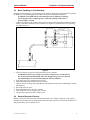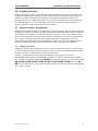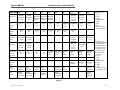
1
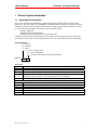
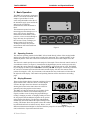
DewPro MMY245 Installation and Operation Manual DewPro MMY 245 Portable Moisture Analyzer Installation and Operation Manual GE Measurement & Sensing Technologies GE General Eastern GE General Eastern DewPro MMY245 Installation and Operation Manual General Notes Attention! This is a portable moisture analyzer. The success and accuracy of moisture measurements and of field validation depends on the integrity of the care exercised in operating this equipment. All fittings and tubing should be tightened properly and examined prior to each use for thread or quick connect fitting damage, leaks or crimped hoses. If any damage is suspected, do not place the unit in service until the suspected damage is repaired. DO NOT alter or modify any of the supplied components. This will not only void the Warranty but could rupture components causing injury or death. Tampering with internal components will likely produce errors in the instrument readings. Caution! Before using or installing the DewPro MMY 245, please read all instructions. Safety! The DewPro MMY 245 Portable Moisture Analyzer is designed for connection to pressurized gaseous systems. Be certain to de-pressurize the system before connecting or disconnecting the hoses or fittings to the analyzer or at the process connection. Disclaimer General Eastern Instruments, Inc. reserves the right to change or modify our products in appearance or performance specifications at any time and without notice. Therefore, information in this document is subject to change without notice and does not represent a commitment on the part of General Eastern Instruments, Inc. No part of this manual may be reproduced or transmitted in any form or by any means, electronic or mechanical, including photocopying and recording, for any purpose without the express written permission of General Eastern Instruments, Inc. Technical Assistance If you should have any questions regarding the product described in this document, or need further assistance, please contact your local General Eastern Instruments (GEI) representative or the factory at 800-33HUMID (800-334-8643). When contacting the factory for technical support, please have your serial number ready. This number is located inside the unit and can be accessed by loosening the two knurled screws on the top of the unit. Serial Number: _______________________________ GE General Eastern DewPro MMY245 Installation and Operation Manual TABLE OF CONTENTS 1 General System Information __________________________________________________3 1.1 Unpacking and Inspection_________________________________________________________3 1.2 System Description_______________________________________________________________4 1.2.1 Portable Trace Moisture Analyzer ______________________________________________________ 4 1.2.1.1 Versatility_____________________________________________________________________ 4 1.2.1.2 Safety ________________________________________________________________________ 4 1.2.1.3 User Friendly Operation__________________________________________________________ 4 1.2.2 Field Validator _____________________________________________________________________ 5 1.3 Theory of Operation _____________________________________________________________5 1.3.1 Sensor Theory______________________________________________________________________ 5 1.3.2 Sample System Operation_____________________________________________________________ 5 1.3.3 Software Features ___________________________________________________________________ 6 1.3.4 Sample Conditioning Practices and Precautions____________________________________________ 6 1.3.4.1 Internal Construction ____________________________________________________________ 6 1.3.4.2 Avoid Liquid Samples ___________________________________________________________ 6 1.3.4.3 Avoid High Temperatures ________________________________________________________ 6 1.3.4.4 Avoid High Pressure Samples _____________________________________________________ 6 1.3.4.5 Hazardous Gas Handling _________________________________________________________ 6 1.3.4.6 Avoid Particulate Contamination___________________________________________________ 6 1.3.4.7 Avoid Corrosive Chemicals _______________________________________________________ 7 1.3.4.8 Avoid Ambient Air _____________________________________________________________ 7 1.3.4.9 Piping Recommendations_________________________________________________________ 7 Dimensions _________________________________________________________________________7 Basic Operation ________________________________________________________________8 2.1 Operating Controls ______________________________________________________________8 2.2 Display Elements ________________________________________________________________8 2.3 Basic Sampling or Spot-Checking __________________________________________________9 2.4 General Operation Practice _______________________________________________________9 2.4.1 Mapping spot check route____________________________________________________________ 10 2.4.2 Temporary Monitoring ______________________________________________________________ 10 2.4.3 Moisture Measurement Practice _______________________________________________________ 10 2.4.3.1 Checking Dryer Performance_____________________________________________________ 10 2.4.3.2 Quality Assurance _____________________________________________________________ 11 2.5 Instrument Setup / Programming _________________________________________________11 2.5.1 Matrix Orientation _________________________________________________________________ 11 2.5.2 Special Functions of the Push Buttons __________________________________________________ 13 2.5.3 Function Guide ____________________________________________________________________ 13 2.5.4 Matrix Field Details ________________________________________________________________ 13 2.5.5 Special Output and Input Functions ____________________________________________________ 15 2.5.6 Interconnection ____________________________________________________________________ 16 2.5.6.1 External Power Option__________________________________________________________ 16 2.5.6.2 External Scalable Input Option. ___________________________________________________ 16 2.5.6.3 Voltage Inputs ________________________________________________________________ 16 2.5.6.4 Output connections ____________________________________________________________ 17 3 Troubleshooting ___________________________________________________________17 3.1 General Troubleshooting Practice _________________________________________________17 3.2 Error Codes ___________________________________________________________________18 4 Field Validator Operation ___________________________________________________19 GE General Eastern DewPro MMY245 Installation and Operation Manual 4.1 Optimum Validation Practice _____________________________________________________20 4.2 MMY 3 Transmitter Preparation__________________________________________________21 4.3 Validator Connection Options ____________________________________________________21 4.3.1 4.3.2 4.3.3 4.3.4 Transmitter Vent (series) Connection ___________________________________________________ 22 Vacuum Application Connection ______________________________________________________ 22 Parallel Connection_________________________________________________________________ 23 Closed Loop Connection ____________________________________________________________ 24 4.4 Field Validator Setup____________________________________________________________25 4.4.1 4.4.2 4.4.3 Matrix Orientation _________________________________________________________________ 25 Single Point Validation Function Guide _________________________________________________ 26 Two-point Validation Function Guide __________________________________________________ 26 5 Troubleshooting Validator Operation __________________________________________27 6 Instrument Specifications____________________________________________________28 7 Appendix _________________________________________________________________29 GE General Eastern 2 DewPro MMY245 Installation and Operation Manual 1 General System Information 1.1 Unpacking and Inspection Upon receipt of the DewPro® MMY245, examine the shipping carton for broken or open packing, distortion, or any other evidence of mishandling. If inspection indicates damage to the unit or any of its components, notify the carrier (within 15 days of delivery) and request an inspection. Move the carton to a clean work area and unpack. The carton you receive should contain: DewPro® MMY245 Installation and Operation Manual All MMY 245 accessories ordered as separate line items Compare the model number with the product structure below to ensure proper receipt of order. If an error should be discovered, do not put the instrument into service and contact the factory immediately. Product Structure 1 Certification R Standard Y Other 2 Pressure Compensation R Basic configuration P Pressure sensor built-in for ppm compensation MMY245- Accessories Part No. 63005033 63005032 63004006 63004005 Description Carrying case including shoulder strap Shoulder strap Cable assembly, MMY 245 to DewPro MMY 30, RS485 cable Connector/cable assembly, RS485 DewPro (RS 485 communication cable for installation in the transmitter for external connection to P/N 63004006) 63002013 Connector/cable assembly, external power and non-I.S. outputs. Gas Connection Accessories 63000598 Gas Inlet and outlet connection, ¼” tube 316 SS 63002201 Gas Inlet and outlet connection, 6mm tube 316 SS 63002199 Gas inlet, 3 ft. PFA hose with quick connect set and ¼” tube process connection 63002200 Gas inlet and outlet connection, ¼” tube PFA 63005036 Coalescing Filter for Glycol Contactor Applications 63005037 Pressure Regulator for samples greater than 125 psig. GE General Eastern 3 DewPro MMY245 1.2 Installation and Operation Manual System Description 1.2.1 Portable Trace Moisture Analyzer The DewPro MMY 245 Moisture Analyzer is designed primarily as a portable moisture instrument that can be used in a variety of gaseous applications. The portable unit can be used to quickly spot check the performance of dryers for compressed air, natural gas. Checking pure gas supplies, accurately testing SF6 gas in high power switchgear and transformers, gasified LNG, breathing air or oxygen and many other applications are easy with the MMY 245 portable analyzer. This is a well balanced, compact, easy to use versatile analyzer complete with all the units of measure and connectability required to keep track of the moisture critical processes in your facility. The rugged DewPro MMY 245 case has been selected to provide the maximum protection for the internal components in most any industrial environment where it is used. With the MMY 245 Portable Moisture Analyzer, measurement time is typically 5 minutes. The sensor is kept in a very dry desiccated environment with the dry-down taking place while the instrument is inactive or being transported to the next measurement point. For complete instrument specifications, see Section 6. 1.2.1.1 Versatility The variety of applications in which the DewPro MMY 245 can be used is limited only by its range of operation for moisture and pressure and by the chemical nature of the gas sample. The unit is designed to be used for dry samples having a dew point temperature below freezing at the pressure of the sample introduced to the unit. Some typical applications are listed below: Desiccant dried air Dried Natural Gas Argon gas for welding Nitrogen gas supplies Breathing air SF6 gas for switchgear Helium gas supplies Oxygen gas supplies Hydrogen cooling loops Instrument air Glove box gas purifier loops Ethylene Production Heat treating atmosphere Gas Bottle filling operations … and many others. generators The processes listed above often require many different units of measure and the MMY 245 is able to provide readouts in most of the common units necessary for these applications. The unit of measure is simply selected from the operating keypad. An optional pressure sensor will automatically correct for changes in pressure that occur in a given stream or when spot-checking several sample points throughout a facility or process. 1.2.1.2 Safety The DewPro MMY 245 has been designed to meet or exceed the FM requirements for Class I, Division 1 environments for portable instruments. 1.2.1.3 User Friendly Operation The normal method of measurement is to connect the DewPro MMY 245 to the process sample tap via a short flexible high-pressure hose that employs a quick-connect fitting. The sample valve on the process piping is opened to start a sample flow to the unit. After allowing the sample flow to purge the hose for 15-30 seconds, the handle on the side of the analyzer is rotated up to the vertical position. This directs the sample across the sensor. The power button is pressed and the readout provides the moisture value in the desired unit of measure. The analyzer is programmed using the keypad and a matrix to select the moisture unit of measure, temperature unit of measure and other operating parameters. An optional pressure sensor can provide real time correction for concentration units of measure. In lieu of the optional sensor, a pressure constant can provide the proper value with known pressure conditions. GE General Eastern 4 DewPro MMY245 Installation and Operation Manual 1.2.2 Field Validator This portable unit can validate the readings of permanently installed GEI loop-powered dew point transmitters while they are in the loop, simply by connecting the MMY 245 to the DewPro’s outlet and monitoring the same sample. This is accomplished by monitoring the same sample as the transmitter by connecting to its outlet. Either a single-point or two-point validation mode can be selected via the keypad and matrix. An RS-485 connection between the portable and the transmitter provides for digital correction of the transmitter’s calibration data. The procedure takes from one to four hours and eliminates transmitter downtime and reduces the need for sending transmitters back to the factory for recalibration. The complete description of this feature can be found in section 4 of this manual. This validation is not a field calibration technique since most calibrations require the standard to be four times more accurate than the device under test. The MMY 245 does not have that accuracy advantage and should be used to adjust transmitters in the field with this in mind. 1.3 Theory of Operation The DewPro MMY 245 operates as a self-contained moisture analyzer system comprised of a sensor, electronics, power source, and sample system. The sensor is an advanced Planar Gold/Aluminum Oxide sensor designed to respond quickly to changes in measuring conditions. It has been used extensively in trace moisture analyzers for several years. This trusted sensor is resistant to contamination and has proven to be a rugged and stable platform for consistent results in measurement accuracy and reliability. The electronics package was designed using the basic DewPro technology developed four years prior to the introduction of the portable configuration. With proven reliability and ruggedness and with the addition of memory and energy management components, the MMY 245 provides the flexibility required for many applications. Four standard “D” cell batteries supply the power for the MMY 245. Standard alkaline batteries are included and are recommended for replacement. The internal sample system provides for purging the hoses after they are connected to the sample tap and then directs the sample across the sensor. 1.3.1 Sensor Theory The Planar Gold / Aluminum Oxide sensor is a capacitance based technique for detecting the moisture content in gaseous samples. This sensor is manufactured using semiconductor techniques on wafers of ceramic substrate. The sensor is manufactured by depositing a pure aluminum layer over gold contact pads on a ceramic substrate. The aluminum is partially anodized using a proprietary process and a thin film of permeable gold is deposited over the oxide layer. The aluminum oxide is a porous insulator and provides a space for moisture molecules to reside at equilibrium with the sensor environment. The permeable gold conductive layer allows moisture molecules to move freely into or out from the oxide layer and acts as one plate of the capacitor. The aluminum layer beneath the oxide acts as the opposing plate for the capacitor. After the sensors are created on the wafer, they are diced apart and each sensor is then bonded to a pressure rated feed-through on a probe. The probe supports the sensor in the process environment for which it is rated. 1.3.2 Sample System Operation The main component of the sample system in the DewPro MMY 245 is essentially a valve. The valve emulates a four-way process valve during operation. In the “dry” or horizontal position, the sensor is exposed to a very dry, -85° to –95°F, (-65° to –72°C) dew point environment created by a very strong desiccant. This keeps the sensor dry and ready to measure. Any sensor will respond quickly to increasing moisture and dries down much more slowly. In the “measure” or vertical position of the valve handle, the sample stream is directed across the sensor to allow the measurement to be made. Just as in a four-way process valve, there is a second function in operation concurrent with the “flow” description above. When in the “dry” position, the passage for the sample connection inlet is connected to the outlet for purging the connecting hoses. This purging operation is critical for making the measurement as quickly as possible since a fresh sample is transferred to the immediate sensor location GE General Eastern 5 DewPro MMY245 Installation and Operation Manual while the sensor itself is kept dry and ready to measure. Purging for 3-5 minutes is recommended. In the “measure” position of the valve handle, the desiccant chamber is closed from any possible contact with the incoming sample gas. This prevents the desiccant from being contaminated or consumed too quickly. The desiccant should last several months under daily use for several readings per day. An optional pressure transducer can be ordered to provide pressure information to the electronics for compensation of readings in concentration units of measure. These units of measure require a total pressure value to correctly compute the proper moisture reading. The pressure information can be displayed and used for correction of the moisture reading from this pressure sensor or from a direct input of a constant value as selected using the keypad. 1.3.3 Software Features The software architecture is based on a matrix of operating parameters. Each parameter setting determines the function of the software to display and compute the proper moisture value, to control outputs and to communicate with field mounted MMY series transmitters. The matrix settings also determine how to treat optional inputs and when they should be used in the computation of a moisture value. The complete operation of the matrix is described in the Instrument Setup portion of the Basic Operation, Section 2 in this manual. 1.3.4 Sample Conditioning Practices and Precautions 1.3.4.1 Internal Construction All the wetted surfaces of the MMY 245 DewPro are electro-polished non-hygroscopic metal components of either stainless steel or anodized aluminum. Introducing clean samples will prevent these surfaces from becoming contaminated. 1.3.4.2 Avoid Liquid Samples Avoid ANY liquid exposure of the sample lines and the instrument. Liquids will damage the unit and void the Warranty. 1.3.4.3 Avoid High Temperatures Avoid high or low temperatures. The MMY 245 can be operated over a temperature range of 4°F to 104°F (-20° C to +40° C). Operating the unit at higher temperatures can damage the sensor and the electronics. The LCD is not likely to work if the unit is operated below the normal stated range. 1.3.4.4 Avoid High Pressure Samples The maximum inlet pressure rating for the MMY 245 is 150 PSIG or 10 Bar. If the process or sample pressure is greater than this, a pressure regulator should be used to drop the pressure to within the instruments range. 1.3.4.5 Hazardous Gas Handling When making connections to samples of flammable or hazardous gases, exercise care to insure leak free connections. Be aware that leaks can create fire, explosive or toxic conditions that should be avoided. The MMY 245 is designed to meet Class I, Division 1, Group B-G environments; but the integrity of the sample connections to the instrument is the responsibility of the user. 1.3.4.6 Avoid Particulate Contamination A sample contaminated with particulates will deposit some of this material inside the unit producing more surface area and sites where moisture could be trapped. This could result in higher than actual readings. If the sample contains particulates or aerosols, it must be filtered to remove this contamination. GE General Eastern 6 Installation and Operation Manual DewPro MMY245 1.3.4.7 Avoid Corrosive Chemicals Introducing corrosive chemicals can pit or corrode the internal components and can damage the sensor. Avoid attempting measurements in streams containing chlorine, HCl, and other strong acid or base gases. 1.3.4.8 Avoid Ambient Air The MMY 245 is a trace moisture analyzer. Ambient air can contain as much as 2% water. The instrument is capable of measuring down to sub ppmv moisture in samples to 150 psig, so avoid leaving the operating handle in the measure position when not connected to a sample flow. Ambient air exposure over long periods of time can move large amounts of moisture into the measurement cell and eventually cause the sensor to drift. 1.3.4.9 Piping Recommendations Connection the MMY 245 to the process or sample tap in the proper manner will insure the most accurate measurements. Connecting tubing should be made from materials that are non-hygroscopic and capable of handling the sample pressure. Keeping the length of connecting tubing as short as possible will allow faster readings since the moisture in the sample arrives quicker than with longer lines. Materials that are recommended include stainless steel, and PFA tubing especially for dew points below –65°C, Copper and PTFE tubing. Rubber, Tygon and other plastic or polymer tubing is NOT recommended for ANY application. Insure that all connections at the sample tap and at the instrument are leak tight. 1.4 Dimensions Figure 1 GE General Eastern 7 Installation and Operation Manual DewPro MMY245 2 Basic Operation The MMY 245 operation is simple and intuitive. Provide the instrument with a sample of gas and direct it to the sensor using the handle on the side of the instrument, apply power and let the analyzer tell you when the measurement is stable and should be taken. The instrument operates best when measuring pressurized samples over a range of 20-150 psig. Satisfactory measurements can be made at lower pressures, even at vacuum, although a longer time may be required since there are not as many exchanges per minute at these lower pressures. Techniques for these low-pressure measurements will be discussed later in this manual. 2.1 - V 0 + POWER V HOME H - Figure 2 Operating Controls The electronic operating controls for the MMY 245 are found directly in front of the carrying handle and the flow path control is located on the left side of the instrument. This “operating handle” of the instrument puts the sensor into a desiccant environment or directs the flow of the sample across the sensor. The electronic controls provide access to the analysis of the sample. These electronic controls consist of six membrane switches (see Figure 2) located below the digital display and are used to power the unit and control the various functions of the unit. The POWER key will turn the unit on or off. The HOME key will display the matrix position V0 H0 or alternately V4 H0. Pressing the V and H keys advances the vertical or horizontal position within the matrix and the display will show the contents of that position. Pressing the + and – keys increments or decrements the value in the matrix cell described in the right side of the display. These matrix and operating functions will be described on succeeding pages. 2.2 Display Elements There are three distinct display elements consisting of a large VH digital readout where values are shown, a smaller digital section to the right where four characters are displayed 00 showing the location in the matrix where the values are generated, and a bar graph across the bottom. The MMY 245 takes the guesswork out of waiting for the Stable Reading measurement to stabilize. The instrument display (see Figure3) includes a rate-of-change bar graph indicating a VH reading is changing or stable. A changing reading will cause the bar graph to include additional segments in any portion 00 of the bottom of the display. The direction and amplitude illustrated by the arrows indicate the required change in the reading. This feature allows the operator to know the reading Reading Still Changing has stabilized and can be recorded correctly. Below, several Figure 3 different measurement techniques are discussed from the perspective of connecting the sample to the unit; but the basics of operation remain the same. -48.6 -48.6 GE General Eastern 8 Installation and Operation Manual DewPro MMY245 2.3 Basic Sampling or Spot-Checking Sampling or spot-checking of a pressurized gaseous sample is the primary design function of operation the MMY 245. The following general procedure describes this fundamental operation: WARNING! The MMY 245 has a maximum pressure of 150 psig or 10 bar(g). Connecting the unit to a sample pressure could cause damage to the unit or personal injury or death. 1. Connect the analyzer to the sample source connection using either hard tubing and the appropriate fittings, or the hose and fitting set P/N 63002199 (see Figure 4.) and initiate the flow by opening the sample tap valve. Figure 4 2. Allow the sample to purge the connecting tubing for a few minutes. WARNING! If there is any evidence of aerosols or the presence of condensate in the exhaust, DO NOT PROCEED. The unit is designed for gaseous use only and any liquid droplets or aerosols will damage the desiccant chamber. 3. Turn on the power by pressing the power switch. 4. Rotate the handle to the measure position (vertical). 5. Observe the rate-of-change bar graph indicator until both arrowheads appear indicating the reading has stabilized. 6. Record the moisture value. 7. Rotate the handle back to the “dry” position. 8. Turn off the power by pressing the power switch. 9. Disconnect the analyzer from the sample source. 2.4 General Operation Practice Making a moisture measurement with the DewPro MMY 245 is simple but there are some general moisture measurement practices that should be followed. If these practices are followed, the MMY 245 will provide many years of reliable service. GE General Eastern 9 DewPro MMY245 Installation and Operation Manual 2.4.1 Mapping spot check route If more than one sample point is to be checked on a regular basis, it is best to map out the route the operator should follow. If time permits, the route should be chosen for the best measurements instead of the shortest distance traveled. Simply stated, this method measures the driest sample first and moves through the route from the measurements that have proven to be the driest to the wettest in sequence. This allows the sensor to respond faster since getting wet is naturally faster than getting dry. This routing can only be determined by trial and keeping good records. 2.4.2 Temporary Monitoring The MMY 245 is to be used in either a spot check mode or a temporary measurement mode. A spot check mode is when an operator takes the unit to a sample tap and measures the moisture in the sample and disconnects the unit and moves on to perhaps the next sample tap. Temporary moisture monitoring is where the instrument is to be left connected to a sample unattended and the moisture values recorded electronically or by periodic observation. The MMY 245 is supplied with two analog outputs for conveniently connecting to an external recording or logging device. The battery life can support this mode of operation for a few weeks but the unit also provides for an external DC power source to power the unit. These connections are made using the cable connection on the front of the unit. The cable can be ordered as an accessory. Warning: Neither of these connections should be used in hazardous or electrically classified areas. 2.4.3 Moisture Measurement Practice Every process and application is different and these differences must be considered; but using good general practices will result in better and more accurate measurements. 1. Do not introduce samples at greater than the rated pressure of 150 psig (10 barg). 2. Do not introduce samples of gases corrosive to aluminum or gold into the unit. This will damage the sensor and will void the warranty. 3. Do not introduce samples of known high moisture or samples saturated with water into the unit. The sensor can be damaged and will not be covered under warranty. Observe the outlet port to see if the escaping sample shows evidence of aerosols. If so, do not attempt the measurement. If an attempt is made to measure a sample that drives the reading off scale high, move the black handle into the bypass position immediately to dry the sensor. 4. Do not introduce dirty samples into the instrument. Filter contaminated or oily streams to prevent contamination of the sensor and internal piping. 5. Insure plumbing connections are tight. A leak will introduce errors in the measurement, 6. Keep sample lines to measurement taps as short as possible using small diameter (¼”) tubing to achieve the best response speed. 7. Use stainless steel, copper or PFA Teflon tubing for sample connections for best results. 8. Allow sufficient time to purge the new sample through the sample lines to insure a fresh sample is provided to the analyzer. This may take a minute or two if the sample tap connection is mounted directly to the pipe or several minutes if the sample line is necessarily longer to reach the source. 9. Keep good records of periodic measurements. This will allow better planning for maintenance of process equipment and measurement practices. 2.4.3.1 Checking Dryer Performance Gas dryers often vary in their ability to dry the gas at any given point in time. Spot checking a dryer can often produce readings that vary depending on the load of gas flowing through it, the cycle or stage of operation for the dryer and the condition of the dryer internal mechanical and or chemical elements. Good record keeping and tracking the initial measurements for longer periods can be helpful in determining the typical dryer performance in a specific system. GE General Eastern 10 DewPro MMY245 Installation and Operation Manual 2.4.3.2 Quality Assurance Quality checks of gas supplies can be made easily with the MMY 245. The basis for the measurement should be established prior to making any actual readings. Typically the readings for gas quality are made in ppmv and the instrument can be configured to provide this information accurately. The parameters of pressure are important to making any concentration measurement so the instrument can be configured properly. A review of the quality specifications between the supplier and the user is helpful to determine acceptable moisture measurement practice. 2.5 Instrument Setup / Programming In addition to preparing the hardware for connection to process fittings, the analyzer should be checked for the proper operation. Configuring the MMY 245 is made simple using a matrix format. The diagram for the matrix is located on the rear panel of the analyzer (See Figure 5). The 10 X 10 matrix contains all the operating parameters for properly displaying and calculating the correct value in the appropriate unit of measure. The control functions for the outputs and interface connections are easily set by moving through this matrix and selecting the appropriate values for each cell. The following section describes the features and usage of the various matrix locations as they apply to the MMY245. 2.5.1 Matrix Orientation The display of the DewPro MMY245 shows the current matrix location at all times, using the vertical (V or row) and horizontal (H or column) coordinates. (Note: A matrix programming card, similar to the one shown in Figure 5 is mounted to the outside of the enclosure). Example: The position for the unit of measure selection is location V0H1. (See Figure 5.) Movement through the matrix is accomplished by using the “V” and “H” buttons to move to another row or column. For example, beginning at V0 H0 and successively pressing “V”, leads the user to V1 H0, V2 H0, V3 H0, V4 H0, V5 H0, V6 H0, V7 H0, V8 H0, V9 H0 and back to V0 H0. At any location where a value may be changed by the user, the digit to be altered is selected using the “+” and “-” buttons. GE General Eastern 11 DewPro MMY245 M M Y245 H0 V0 Channel 1 V1 Output 1 Scale V2 Output 1 Scale V3 Channel 1 Setup V4 Channel 2 V5 Scale Output 2 Opt. Input Installation and Operation Manual H1 H2 H3 Display Display Moisture Moisture Minimum Maximum Event Event H4 H5 H6 Output 1 at Fault 0=-0.1V 1=5.1V 2=hold Reset Moisture Min/Max Events Display Moisture Value Select Moisture Unit Td °C 0V Td °C 5V Td °F 0V Td °F 5V ppm v 0V ppm v 5V g/kg 0V g/kg 5V % RH 0V % RH 5V P Td °C 0V P Td °C 5V Pressure Constant in bar Pressure Td Constant in bar Output 1 Enable 0=Disable Display 2nd CH. Value Select 2nd CH. Value Output 2 at Fault 0=-0.1V 1=5.1V 2=hold Temp. °C 0V Temp. °C 5V bar 0V bar 5V lbs/MMSC lbs/MMSCF F 5V 0V P Td °F 0V Min. Input Max. Input Minimum Display Display Input Value Value Voltage V6 V7 Special V9 Service Double Pt. Dewcomp 1=begin Double Pt. State 100=OK Display Display Primary Secondary Error Code Error Code H8 H9 Display Moisture A/D g/m³ 0V g/m³ 5V Output 1 D/A Cal. 0V Output 1 D/A Cal. 5V Maximum Input Voltage Temperature A/D Minimum Output Voltage Output 2 D/A Cal 0V Maximum Output Voltage Output 2 D/A Cal 5V Single Pt. Single Pt. DewComp State 1=begin 100=OK Battery Auto-off Capacity Time Remaining Minutes Input Locking 50=Unlock Unit ID Reset to Defaults 50=Reset System Reset 50=Reset Software Version Location V0 H1 0 = Td °C 1 = Td °F 2 = ppm v 3 = lbs/MMSCF 4 = g/m³ 5 = g/kg 6 = RH 7 = Pressure Td °C 8 = Pressure Td °F P Td °F 5V Output 2 Enable 0=Disable Channel 2 Setup V8 H7 Location V4 H1 0 = Temperature °C 1 = Temperature °F 2 = Pressure psig 3 = Pressure psia 4 = Pressure bar 5 = Scaled Input Voltage 6 = Td °C 7 = Td °F 8 = ppm v 9 = lbs/MMSCF 10 = g/m³ 11 = g/kg 12 = RH 13 = Pressure Td °C 14 = Pressure Td °F Figure 5 GE General Eastern 12 DewPro MMY245 Installation and Operation Manual 2.5.2 Special Functions of the Push Buttons (a) Reset to “Normal” Display Pressing the “Home” button returns the user to V0 H0 (normal display). Pressing the “Home” button again V4 H0 is displayed representing the temperature or the unit of measure selected in V4 H1. Pressing “Home” repeatedly alternates the displayed unit between V0 H0 and V4 H0 (b) Display Only Note that fourteen (14) matrix locations are for display only and may not be changed by the user (refer to Figure 5). For convenience, input (or programming) fields have a flashing digit in the display, whereas “display only” fields do not. The “display only” fields are as follows: V0 H0 = Display Moisture Value V0 H2 = Display Moisture Minimum Event V0 H3 = Display Moisture Maximum Event V0 H8 = Display Moisture A/D V3 H0 = Pressure Constant in bar (if pressure sensor option is installed) V4 H0 = Display 2nd Channel Value V4 H8 = Temperature A/D V8 H1 = Double Point State 100 = ok V8 V8 V9 V9 V9 V9 H3 = Single Point State 100 = ok H5 = Battery Capacity Remaining (%) H0 = Display Primary Error Code H1 = Display Secondary Error Code H2 = Unit ID H3 = Software Version 2.5.3 Function Guide Using the Matrix (refer to Figure 5). The matrix is organized in functional families by rows. The following is a general description of these functional families indicating the row in which they can be found. Row Family of Functions Channel 1, selection of the moisture unit, fault events V0 V1/V2 Scaling the output 1 to a selected unit of measure for moisture Pressure constant, output 1 hardware set-up V3 Channel 2, selection of second unit of measure i.e. temperature, second moisture unit V4 or scaled input Scaling of second output and option input V5 Output 2 hardware set-up V7 Special functions V8 Service information V9 2.5.4 Matrix Field Details Not all of the cells in the matrix are used. Below are descriptions for specific cells that are used to control the operation of the instrument. Note: a portion of the V8 row will be explained in section 4 since this row refers to the interface with the MMY 30/31 series transmitters. GE General Eastern DewPro MMY245 Installation and Operation Manual Note: To assist in setting a value in a cell, the cursor (flashing digit to be altered) can be moved from the digit to digit, right to left, by pressing the V and H button simultaneously. Cell Function V0 H0 Displays moisture unit selected in V0 H1 V0 H1 Entering a number from 0 to 8 selects desired moisture unit displayed in V0 H0 V0 H2 V0 H3 V0 H4 V0 H7 V0 H8 V1 H09 and V2 H0-7 V3 H0 V3 H1 V3 H7 V4 H0 V4 H1 (see table location V0 H1 on the matrix illustration). Note: Selecting 7 or 8 displays the pressure dew point in V0 H0 as a function of the pressure value entered in V3 H1. Example: The process pressure is 100 bar and is to be measured by reducing the gas sample to the MMY 245 to atmospheric pressure. If the pressure dew point temperature is desired, entering 100 bar in V3 H1 the dew point for 100 bar is calculated and displayed in V0 H0 or V4 H0 (second unit of measure) if selected from table location V4 H1 (see matrix illustration). If a concentration unit, i.e. 2 = ppmv, 3 = lbs/MMSCF, 4 = g/m3 is selected, inlet pressure can be compensated for up to 10 bar. The actual sample pressure must be entered in bar(a) in V3 H0. This pressure value covers process pressures up to 10 bar(g) that can be connected directly to the MMY 245 system (10 bar(g) maximum). Dynamic pressure compensation can be accomplished if the optional pressure sensor is installed (10 barg max.). Displays the lowest moisture value measured since the unit was reset using V0 H4, new batteries were installed, system reset performed using V9 H9, or unit of measure selection is changed. Displays the highest moisture value measured since the unit was reset using V0 H4, new batteries were installed, system reset performed using V9 H9, or unit of measure selection is changed. Resets the event memories of V0 H2 and V0 H3 by pressing the + button Fault status for output 1 is selected with 0 setting the output to -0.1 V, 1 setting the output to 5.1 V and 2 holding the output to the last measured value with the occurrence of a memory or output error. Displays the raw digital value corresponding to the moisture content, and can be verified using the calibration table supplied with the instrument. This value is equal to the “counts”/10 as illustrated on the calibration data sheet furnished with the instrument. Scaling the moisture output. The low moisture value is assigned to 0 V, the high moisture value is assigned to 5 V. A pressure value between 0.01 and 99.99 bar can be entered correcting concentration units (see explanation under V0 H1). A pressure value from 0.1 to 999.9 bar can be entered to calculate the process pressure dew point (see explanation under V0 H1). Enables output 1 by entering a digit other than 0, disables the output 1 by entering a 0. Displays the second unit of measure that normally would be the temperature. However, any other unit (see table location V4 H1 on the matrix illustration) can be assigned to this matrix field choosing a number from 0 to 14 in V4 H1. Selects the second unit of measure displayed in V4 H0 from the table in location V4 H1 on the matrix illustration. GE General Eastern 14 DewPro MMY245 Installation and Operation Manual Cell Function V4 H7 Fault status for output 2 is selected with 0 setting the output to -0.1 V, 1 setting the output to 5.1 V and 2 holding the output to last valid measured value with the occurrence of a measuring error. Displays the raw digital signal corresponding to the temperature value. This value is only used for troubleshooting at the request of a factory technician. Scaling the output the low temperature value is assigned to 0 V. The high temperature value is assigned to 5 V. Scaling the output voltage to either 0 or 1 to 5 Volts, the low value is entered here (0 V = minimum). Scaling the output voltage to a voltage up to 5 V, the high value is entered here (5 V = maximum). Enables output 2 by entering a digit other than 0, disables the output 2 by entering 0. Displays the remaining battery capacity in %. It is recommended to renew the batteries when the display is <15%. The number programmed determines the operating time in minutes after which the unit will turn itself off to save battery energy. If set to zero the instrument will operate in a continuous mode. The range available is 1 to 19999 minutes. Selecting a number other than 50 will lock the matrix, values in the matrix fields can be viewed but not changed inadvertently or to avoid tampering by unauthorized persons. Entering 50 unlocks the matrix allowing changes in matrix fields. In case of a fault condition, an error code is displayed enabling the user to identify any software errors when communicating to the factory technicians. See the trouble shooting section for details. The error preceding the current error displayed in V9 H0 is indicated enabling the user to identify any hardware errors when communicating to the factory technicians. The instrument is identified by a series ID number that currently is 150. The software version implemented is displayed. Entering 50 enables the user to reset the instrument to factory defaults without affecting the calibration data. This function may help if the user feels they got lost while setting function values. Entering 50 resets the system after calibration equaling a power off and on. This is merely a factory or expert function. V4 H8 V5 H0 V5 H1 V5 H8 V5 H9 V7 H7 V8 H5 V8 H6 V8 H9 V9 H0 V9 H1 V9 H2 V9 H3 V9 H5 V9 H9 2.5.5 Special Output and Input Functions Outputs can be used for temporary, unmanned, monitoring of moisture in a process or environment by connecting the MMY 245 to a recorder or data logger. The outputs can be scaled using the matrix to allow study of moisture over a specific range for a period of time. The MMY 245 can also accept inputs from external transmitters for display locally on the unit. This feature can be useful in the field to monitor process information locally. The external transmitter signal can be connected to the MMY 245 and the signal scaled to allow that scalable parameter to be displayed in addition to the moisture value. Cell Function V3 H8 Calibrates the output 1 hardware at 0 V: connecting a voltmeter to the output the displayed number can be increased or decreased using the + and - button to adjust the voltmeter reading to 0 V (Value is around 500). This is factory calibrated. GE General Eastern 15 DewPro MMY245 Installation and Operation Manual Cell Function V3 H9 Calibrates the output 1 hardware at 5 V: connecting a voltmeter to the output the displayed number can be increased or decreased using the + and - button to adjust the voltmeter reading to 5 V (Value is around 2500). This is factory calibrated. Scaling the output the low pressure value is assigned to 0 V. The value indicated will assign the “0” volt output to track the pressure transmitter. It will also function to respond to the pressure constant if no optional pressure sensor is installed. The high pressure value is assigned to 5 V. The value indicated will assign the “5” volt output to track the pressure transmitter. It will also function to respond to the pressure constant if no optional pressure sensor is installed. Using the scaled input with any sensor (e.g. oxygen sensor) the low value to be displayed is entered here. Using the scaled input with any sensor (e.g. oxygen sensor) the high value to be displayed is entered here. The minimum voltage (0 V = minimum) external sensor electronics would supply is entered here in Volts. The maximum voltage (5 V = maximum) external sensor electronics would supply is entered here in Volts. Calibrates the output 2 hardware at 0 V: connecting a voltmeter to the output, the displayed number can be increased or decreased using the + and - button to adjust the voltmeter reading to 0 V (Value is around 500). This is factory calibrated. Calibrates the output 2 hardware at 5 V: connecting a voltmeter to the output the displayed number can be increased or decreased using the + and - button to adjust the voltmeter reading to 5 V (Value is around 2500). This is factory calibrated. V5 H2 V5 H3 V5 H4 V5 H5 V5 H6 V5 H7 V7 H8 V7 H9 2.5.6 Interconnection The MMY 245 can be powered from an external DC power supply and can provide voltage outputs for recording purposes. The paragraphs below describe these functions. WARNING! The MMY 245 is not designed to be connected to either an external power supply or external signals for inputs or outputs in hazardous or electrically classified areas. 2.5.6.1 External Power Option The DewPro MMY245 can be powered with 6-12 VDC using the power and output cable P/N 63002013. This cable will allow connection of the DC power using the Red (+) and Black (-) wires per the drawing MSY35C in the appendix of this manual. WARNING! The MMY 245 has a maximum voltage specification of 12 VDC. Connecting the unit to a higher voltage could cause damage to the unit and will void the warranty. 2.5.6.2 External Scalable Input Option. The DewPro MMY245 can display an external analog input using the power and output cable P/N 63002013. 2.5.6.3 Voltage Inputs The cable P/N 63002013, will allow connection of the DC 0/1-5 VDC signal using the Orange (+) and Black (-) wires per the drawing MSY35C in the appendix of this manual. This input can be scaled and GE General Eastern 16 DewPro MMY245 Installation and Operation Manual displayed using the procedures for V5 H4, V5 H5, V5 H6, and V5 H7. See the section 2.5.5 above titled 2.5.5 Special Output and Input Functions. 2.5.6.3.1 Current Inputs When reading a 4-20 mA signal from an external device, use a 249 Ω resistor across the wires for a 1-5 VDC input. Example Conditions: 1. Input device is a MMY30 with –90 to +10 as the 4-20mA span settings. 2. Sense resistor is 249 Ohms 3. Output voltage of MMY245 must span 1 to 5 volts given the 4-20mA span of the MMY30. Required Settings: 1. V5 H4 = -90 2. V5 H5 = 10 3. V5 H6 = 1.00V (4mA * 249 Ohms = 0.996V ≈ 1.00V) 4. V5 H7 = 4.98V (20mA * 249Ohms = 4.98V) 5. V5 H8 = 1.00 6. V5 H9 = 5.00 Therefore as the 4-20mA signal is sensed by the 249 Ohm resistor as a voltage between 1.00 and 4.98 volts, the display in matrix location V4 H0 will show a linear value between –90 and +10 with a voltage output between 1.00 and 5.00 volts to match. 2.5.6.4 Output connections The DewPro MMY245 can provide 0-5 VDC outputs for recording or logging the readings using the power and output cable P/N 63002013. This cable will allow connection of the DC power using the Green (+ for output 1) and Black (-) or the White (+ for output 2) and Black (-) wires per the drawing MSY35C in the appendix of this manual. The output impedance is 100 Ω. This must be connected to a recorder or logger with an input resistance of at least 20 KΩ to provide 0.5% accuracy. A higher input impedance is recommended for better signal accuracy. These outputs are scaled and referenced to specific units of measure using V1 H0, through V2 H7 for output 1, and V5 H0 through V5 H4 for output 2. See the section 2.5.5 above titled 2.5.5 Special Output and Input Functions. 3 Troubleshooting Field maintenance consists of keeping the instrument clean replacing the batteries when the unit indicates they are low (see V8 H5). In addition, monitoring the reading after leaving the handle in the bypass position over night will provide an indication of how well the desiccant can dry down the sensor. If this reading is above –30°C dew point, return the unit to the factory for desiccant replacement and service. 3.1 General Troubleshooting Practice Troubleshooting will be helpful in case the instrument does not perform and has an error indication on the display. This troubleshooting guide is limited to the function of the unit and is not intended to address questionable readings where there is no error code present. Suspected errors in readings should be dealt with first by insuring all connections are leak free and that the unit of measure is correctly set. The pressure compensation mode should be verified that it is set correctly for the application. After these items are verified to be correct, and if the unit still produces questionable readings, contact the General Eastern factory field service department by calling 800-33HUMID (334-8643) for further assistance. General Troubleshooting Guide GE General Eastern 17 DewPro MMY245 Installation and Operation Manual Problem Display reads high with handle in the bypass position. Display has a lightning bolt symbol appears steady in the display and reading is missing or doesn’t make any sense. Cause Desiccant is expended Error has occurred or instrument is offscale Display reads fine but the lightning bolt symbol is flashes. Low Batteries 3.2 Remedy Contact Factory 1. Connect to a dry gas source 2. Consult Error Code Chart 3. Contact the factory Change batteries. Error Codes The following procedure is designed to narrow the search for a problem with the MMY 245. It will not provide answers regarding all questionable readings since many external influences such as leaks, can affect the actual readings properly processed and displayed on the unit. Error codes will remain until the condition is cleared. They will clear automatically when the condition causing the error disappears. For specific remedies, contact the General Eastern factory field service department by calling 800-33HUMID (334-8643) for further assistance. Software errors V9 H0 Error Description 0 No Error 1* Dew point < -100C 2* Dew point > 20C 4 Voltage output on CH1 scaled to < 0V 8 Voltage output on CH1 scaled to > 5V 16 Temperature out of range 64 Voltage output on CH2 scaled to < 0V 128 Voltage output on CH2 scaled to > 5V * An error indicating that the dew point is both < -100C and > 20C indicates that the output on CH1 cannot be calculated because of an error reading the temperature. Hardware errors V9 H1 Error Description 0 No error 1 Low battery 2 Sensor shorted 4 Sensor Open Under many situations more than one error can occur at a given time. To determine which error(s) are active, use the following algorithm: 1. Find the largest error number on the above table that is smaller than or equal to the error indicated on the MMY245. 2. Note this error and subtract the value from the MMY245 error code. Return to step one using the remainder. Continue this process until your remainder is zero. For example if the error indication is 80 then: 1. 64 is the largest error that fits in 80 so “Voltage output on CH2 scaled to < 0V” is true. Now subtract 64 from 80. The remainder is 16. 16 is the largest error that fits in 16 so “Temperature out of range” is true. Now subtract 16 from 16. The remainder is 0. This indicates there are no more errors occurring. GE General Eastern 18 DewPro MMY245 Installation and Operation Manual 4 Field Validator Operation In addition to being a versatile moisture analyzer for spot-checking gaseous streams, the DewPro MMY245 may also be used as a field validator for most versions of the permanently mounted DewPro MMY3 series loop-powered transmitters. The following is a list of the model numbers that are supported by the MMY 245: MMY 3 (0, 1)(R, A, B, C)(1, 2)(A, B, C, D)(1, 2)(A, B, C) Version 1 MMY 3 (all) Version 2 The version number is not encoded in the model number or noted on the identification plate. Is identified by the configuration of the terminal board inside the unit. Figure 6 shows the difference in the two versions. Display Connector Socket Version 1 (no socket) Version 2 (with socket) Figure 6 For model numbers not listed above, contact the factory for recalibration and certification. The DewPro series transmitter concept includes a method for validating units in the field using a standard moisture sensor to compare measurements while the transmitter was in service. This feature has been incorporated into the MMY 245 with the flexibility of performing either a single point calibration or a twopoint calibration while the transmitter remains in operation. The primary function is to verify whether a permanently mounted transmitter is functioning properly, and in calibration and, if not, then apply the correct data to the EEPROM to realign its reading. Although factory recalibration of the MMY 245 analyzer is recommended every 6-12 months depending on use as a spot check instrument, it should be recalibrated within 4 months prior to MMY 3 series transmitter field validations. When the MMY 245 is used to field-compensate a DewPro MMY 3, the transmitter will most often remain in service throughout the procedure eliminating down time, recalibration and shipping costs. Another intrinsic benefit of performing a validation in-situ is that the unit is verified to be correct at the exact measuring range where it will normally operate. This is usually a more limited range than that of the factory calibration and thus can actually reduce small cumulative errors over the narrower range. The validation can be either a single point (recommended) or a 2-point compensation (low and high dew point). For either method, the MMY 245 is connected to the same sample as that for the MMY 3 transmitter and monitors the sample and the performance of the on-line transmitter. The reading(s) are compared and the EEPROM data on board the transmitter is automatically reprogrammed to correct any error(s). GE General Eastern 19 DewPro MMY245 Installation and Operation Manual The mechanical connections are made to the same sample as the MMY 3 transmitter with a short length of small diameter tubing. The sample from the transmitter travels the short distance quickly and the two sensors read virtually the same sample at almost the same time. As soon as the mechanical connection is made, initiate the gas sample flow to the MMY 245 to begin drying down the tubing and fittings. The digital link between the two units is through a two-wire RS-485 connection using Cable P/N 63004006. The cable connection at the MMY 245 is made with a bayonet connector on the front of the portable unit. The cable connection at the MMY 3 is made with a bayonet connector on the conduit housing where Cable P/N 63004005 has been installed. Power to operate the MMY 3 transmitter continues to come from the loop and its internal batteries supply power for the MMY 245. Warning! The initial installation of Cable P/N 63004005 will require opening the transmitter enclosure. If the transmitter is located in a hazardous area, all electrical connections must be performed in accordance with local electrical codes. This may mean that the transmitter be removed to a safe area where the validation can be performed on a similar sample gas. Warning! Do not connect the MMY 245 to an external power source during the validation process. This could damage the unit. After mechanical and electrical connections are made, the MMY 245 should be powered up and the handle moved into the vertical (measure) position to display the reading and begin equilibrating the sensor to the sample moisture content. The bar graph is a good indicator of how stable the reading is and should be monitored to insure the unit is stable (see Figure 3). It is recommended that even after a stable condition is indicated on the display that the unit is allowed another ten minutes to settle before continuing the validation procedure. The two procedures are a single-point validation that simply changes the EEPROM data to move the intercept of the curve, and the two-point validation that changes the slope and intercept. The single-point procedure is very brief requiring the sample readings of both devices to be equilibrated and stable. The data will be automatically be written to the EEPROM of the MMY 3 series transmitter almost immediately once the single-point procedure has been initiated. Upon initiation of the two-point procedure, the instrument will automatically stop and wait after capturing the low moisture value. This is to allow the technician to change the sample conditions for both the transmitter and the MMY 245 to a higher moisture content. Once this has been ‘seen’ by the instrument, it will continue by attempting to capture the higher moisture value for both units for comparison. After this point has been captured, the data will be automatically be written to the EEPROM of the MMY 3 series transmitter. 4.1 Optimum Validation Practice For optimum performance of the field validation technique, the MMY 245 should be factory calibrated within 4 months of validating MMY 3 series transmitters. This will insure that the freshest possible data is used for comparison during the validation process. For the single point calibration the process is very quick. The reason is that the single point calibration assumes that both the transmitter and the MMY 245 are already measuring and equilibrated to the same value in the same stream or sample. The transmitter reading is then checked against that of the MMY 245 and the EEPROM data in the on-line transmitter is programmed almost immediately. If either the transmitter or the MMY 245 are not equilibrated, then the validation of the on-line transmitter will not be reliable. To insure both devices have reached equilibrium, monitor the output of the transmitter for a steady GE General Eastern 20 DewPro MMY245 Installation and Operation Manual state condition and the bar graph on the MMY 245 should be showing both arrowheads before starting the validation. 4.2 MMY 3 Transmitter Preparation The DewPro MMY 3 Series transmitters listed above can be equipped to interface to the MMY 245 for field validations. If the internal cable connection of P/N 63004005 has not been made, the installation procedure is as follows: 1. Remove the MMY 3 enclosure cover (and display for display versions). Enlarged View 2. Remove the conduit plug from the KEY unused hub of the MMY 3 transmitter. Feeding the wire of P/N 63004005 with Triangular the small connector into the electronics Plastic Tab cavity of the transmitter, thread the large connector end into that hub and tighten. Captive 3. The connection for the small plug is Screw located under the blue plastic terminal The Key is the Slot plate. Loosen the captive screw opposite Figure 7 the terminal strip and lift the triangular plastic tab (see Figure 7). 4. Plug the small connector into the black socket on the PC board (Figure 7 enlarged view). 5. Arrange the wires so they won’t get pinched by the plastic tab and secure the tab in place with the captive screw. 6. Reinstall (the display for display versions and) the enclosure cover. The unit is now ready for connection to the MMY 245. The cable connection may remain installed in the transmitter for future validations. 4.3 Validator Connection Options When connecting the MMY 245 as a validator, the object is to get the same sample to the unit as that being measured by the transmitter under test. There are several acceptable methods that are discussed below. Attempting a connection other than those listed may cause inaccuracies or may be detected by the MMY 245 as incorrect and the sequence terminated before incorrect data is programmed to the EEPROM. This software feature can only check for the obvious and may not prevent errors if the connection practices discussed below are not followed. GE General Eastern 21 DewPro MMY245 Installation and Operation Manual 4.3.1 Transmitter Vent (series) Connection This is most popular connection (see Figure 8) since the port is built into the exhaust port of the on-line transmitter. The connection is made to the outlet port using a ¼” NPT-M to ¼” tube compression fitting threaded into the exhaust port of the transmitter. This fitting can be connected to the MMY 245 using the hose and fitting connector accessory. Figure 8 Although the MMY 245 can operate at inlet pressures of up to 150 psig, the MMY 30 transmitter is frequently fitted with an orifice either at the inlet or outlet that will drop the pressure. For convenience, the MMY 245 can be set to correct for this pressure differential and produce the proper validation. If the orifice is at the outlet as in a model MMY 30R1A1A, the setting for the pressure compensation in the MMY 245 must be set for proper pressure compensation. In this case, the sample pressure at the transmitter should be measured and noted for proper configuration of the validator. If the orifice is at the inlet as in M/N MMY 30R1B1A, the setting for the pressure compensation in the MMY 245 must be set to 1 bar. Once the sample connection has been made, the unit should be allowed to purge for at least 10 minutes to provide a true sample to the validator. After purging the system, the selected calibration may proceed by setting the MMY 245 to begin the validation. 4.3.2 Vacuum Application Connection Caution: This connection must be performed with caution since the process must be opened temporarily to the atmosphere in order to connect the MMY 245. Release the vacuum gradually before making the process connection to the MMY 245. GE General Eastern 22 DewPro MMY245 Installation and Operation Manual For the special case where the on-line transmitter is used at negative pressures the MMY 245 can still be used for field validations. Figure 9 The MMY 30 transmitter will either have a plug in place of the outlet orifice or have no process connection as in the case of the MMY 31 or MMY 35 used in vacuum applications. When connecting to a MMY 30, the plug must be removed and the connection adapter to the hose for the MMY 245 must be installed in its place. The plug then can be installed on the unused process port on the front of the MMY 245 (see Figure 9). After all connections are tight, The vacuum can be restored and the validation procedure can begin. The validation process should be allowed to equilibrate for a minimum of 3 hours at vacuum with the operation handle in the vertical position for best results. Reverse this procedure to disconnect the MMY 245. When using the MMY 245 as a validator with a MMY 31 or MMY 35 at either positive or negative pressures, use the parallel connection technique that follows. 4.3.3 Parallel Connection The parallel connection, (see Figure 10), is also an option for the MMY 245. This method requires a second port on the process where the MMY 245 can be connected close to the sample point for the on-line transmitter. The connection for the MMY 245 is made to process typically using a ¼” tube compression fitting adapter threaded into the sample tap on the process piping This fitting can be connected to the MMY 245 using the hose and fitting connector accessory. GE General Eastern 23 DewPro MMY245 Installation and Operation Manual Figure 10 Care should be taken to connect the MMY 245 to systems within the rated pressure range of vacuum to 150 psig. If the process pressure is greater than 150 psig, a pressure regulator should be used to reduce the pressure. Although the MMY 245 can operate at inlet pressures of up to 150 psig, the MMY 30 transmitter is frequently fitted with an orifice either at the inlet or outlet that will drop the pressure. For convenience, the MMY 245 can be set to correct for this pressure differential and produce the proper validation. If the orifice is at the outlet as in M/N MMY 30R1A1A, the setting for the pressure compensation in the MMY 245 must be set for proper pressure compensation. In this case, the sample pressure at the transmitter should be measured and noted for proper configuration of the validator. If the orifice is at the inlet as in M/N MMY 30R1B1A, there is no need to alter the setting for the pressure compensation in the MMY 245. Once the sample connection has been made, the unit should be allowed to purge for at least 10 minutes to provide a true sample to the validator. After purging the system, the selected calibration may proceed by setting the MMY 245 to begin the validation. 4.3.4 Closed Loop Connection A closed loop connection, (see Figure 11), is also an option for the MMY 245. This method requires the proper valving to break the existing closed loop to insert the MMY245 in the loop. The valves should be located on the outlet of the on-line transmitter to provide for insertion of the MMY 245 into the loop. The valves should be closed and the sample tubing between them should be in a “U” shape to allow easy removal. Removing this “U” tube and connecting the inlet and outlet connections of the validator to these valves will complete the process connections. GE General Eastern 24 DewPro MMY245 Installation and Operation Manual Figure 11 Care should be taken to connect the MMY 245 to systems within the rated pressure range of vacuum to 150 psig. If the process pressure is greater than 150 psig, this method of connection cannot be used. Transmitters in this configuration usually are not fitted with an orifice but the model number should be checked to make sure the transmitter is a M/N MMY 30 R1D1A. The validation can proceed with the single point (recommended) or dual point procedures. 4.4 Field Validator Setup 4.4.1 Matrix Orientation Once the electrical and mechanical connections have been made the MMY 245 must be configured for the desired type of calibration. A single point calibration will verify the transmitter reading at the sample dew point. This new value represents a change in the intercept of the calibration curve only. A two-point calibration is performed in the same manner as in a single point validation with the additional step of monitoring a second moisture value (generally that of the ambient air). The MMY 245 values are assumed to be the field standard and are used to reprogram the EEPROM data in the transmitter. These values represent a change in the intercept and the slope of the calibration curve. This procedure requires that the transmitter be valved “off line” and opened to the atmosphere. This is accomplished by disconnecting the sample line to the portable MMY 245 and unscrewing the orifice to allow the sensor to equilibrate with the dew point of the ambient air. The single point calibration is selected by moving through the matrix using the “V” and “H” keys on the portable to the V8 H2 and setting the value to 1. The two-point calibration is selected in the same manner GE General Eastern 25 DewPro MMY245 Installation and Operation Manual by using the location V8 H0 and setting the value of that cell to 1. In either case, the validation process can be monitored by observing the value in V8 H3 or V8 H1, respectively. When the value has reached 100, the EEPROM has been reprogrammed and the calibration is complete. Any negative value shown in the display is an error condition and indicates that the transmitter has not been reprogrammed. 4.4.2 Single Point Validation Function Guide Cell V8 H2 V8 H3 Function The MMY 245 is now used to field compensate a DewPro MMY 3 using the single point compensation (process dew point). The sequence should be preceded by allowing the MMY 245 to stabilize at the sample dew point. This process may take a couple of hours but the bar graph indicator in the display will indicate a stable reading. Entering 1 in this cell begins the compensation procedure. This procedure is very fast, so there is really no need to observe all the intermediate steps shown in the display. Displays the status of the compensation process indicating each step of the progress: Displa Validation Step Completed y 0 Idle. No compensation in progress. 10 Attempting Communication with slave transmitter and downloading constants. 20/30 Calculating and reprogramming new values into the slave transmitter. 100 Successful compensation confirmed. -10 Compensation cancelled early. -20 Communication error after 5 retries. -30 Unrecognized slave transmitter type. 4.4.3 Two-point Validation Function Guide Performing a two-point validation requires the operator to monitor the MMY 245 display as the validation steps are completed. After completing the “30” step and when the display reads “40” the operator must change the conditions of the process or sample to elevate the dew point observed by both units. Cell Function V8 H0 V8 H1 Entering 1 is getting the compensation procedure started. Displays the status of the compensation process indicating each step of the progress: Displa Operation Completed y 0 Idle, no compensation is in progress 10 Attempting Communication with slave transmitter and downloading constants. 20 Testing for dry or minimum dew point 30 Checking slope of dew point change. If the dew point is increasing at more than +10°C in 30 seconds, then lock in the low dew point value and move to the next step. 40 Waiting 15 minutes while seeking a stable high dew point. Please change the sample provided to the two units or open them both to the ambient air by disconnecting the plumbing connections to both units. Allow them to equilibrate to the higher value. 50 Calculating and reprogramming new values into the slave transmitter. 100 Successful compensation confirmed -10 Compensation cancelled early. GE General Eastern 26 DewPro MMY245 Cell Installation and Operation Manual Function -20 -30 -40 Communication error after 5 retries. Unrecognized slave transmitter type. Attempting to compensate with incorrect sensor installed 5 Troubleshooting Validator Operation Field maintenance consists of keeping the instrument clean and replacing the batteries when the unit indicates they are low (see V8 H5). Troubleshooting will be helpful in case the instrument does not perform and has an error indication on the display. This troubleshooting guide is limited to the function of the unit and is not intended to address questionable readings where there is no error code present. Suspected errors in readings should be dealt with first by insuring all connections are leak free and the unit of measure is correctly set. The pressure compensation mode should be verified that it is set correctly for the application. After these items are verified to be correct, and if the unit still produces questionable readings, contact the factory field service department by calling 800- 33HUMID (334-8643) for further assistance. Troubleshooting Guide Problem Display reads high with handle in the bypass position. Display is flashing and has a lightning bolt symbol. Display reads a negative number during the validation procedure. GE General Eastern Cause Desiccant is expended Error has occurred or instrument is off-scale An error has been detected during the procedure. Remedy Contact Factory 4. Connect to a dry gas source 5. Contact the factory Contact Factory 27 DewPro MMY245 Installation and Operation Manual 6 Instrument Specifications Technical Specifications* Operating Voltage: Internal: External: Physical Properties: enclosure dimensions: weight: Display: Enclosure: Sensor: Analog Output Output range: Digital Interface Accuracy: Measurement Range: Primary Readout Units of Measure: Secondary Readout Units of Measure: Repeatability: Pressure Rating: Operating Temperature: Resolution: Calibration: Battery Powered - 4 x “D” Cells 12 VDC Maximum 11” (L) x 7” (W) x 7-1/8” (D) <7 lbs., including 4 common “D” size batteries Large, 4 digit LCD display Rate of change bar graph indicator Low battery indicator Last setup is saved for “Hot Start” power up NEMA 4X/IP66 impact resistant plastic enclosure; intrinsically safe: designed to meet FM Class 1, Division 1, Groups AG Planar Two adjustable and assignable non-I.S. 0-5 VDC -100°C to +20° C adjustable RS-485 with proprietary protocol for calibration and communication to MMY 3 series loop-powered transmitters ± 2° C dew point temperature -100° to +20° C dew point temperature Standard Features • Rugged, yellow NEMA4X/IP66 compact enclosure • Designed to meet Class I, Division 1, Groups A-G pending • Long battery life with 4 common "D" alkaline batteries • Desiccant chamber for fast sensor response • Auto shutoff timer (adjustable) • Non-I.S. voltage outputs Options • Pressure sensor • Hose kit with quickconnect fittings • Carrying Case with shoulder strap Dew Point °C, Dew Point °F, ppmv, Lbs/MMSCF, g/m3, g/kg, % RH Temperature °C, Temperature °F, Pressure psig **, Pressure psia **, Pressure bar **, arbitrary scaled input voltage plus all primary units of measure 1.0° C dew point temperature Full vacuum to 150 psig (10 bar) -20° C to +40° C 0.1° C dew point temperature Factory recalibration recommended every 6-12 months depending on use, within 4 months of MMY 3 series transmitter field validations ** With optional pressure transducer * Specifications subject to change without notice GE General Eastern 28 DewPro MMY245 Installation and Operation Manual 7 Appendix GE General Eastern 29