1
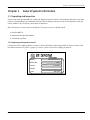
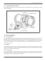
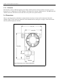
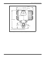
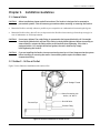
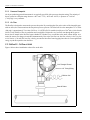
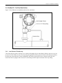
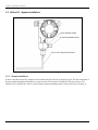
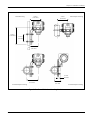
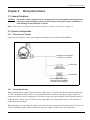
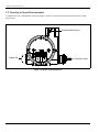
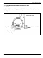
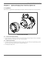
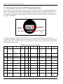
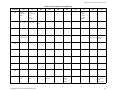
GE
Sensing & Inspection Technologies
Moisture
DewPro® MMY30
Trace Moisture Transmitter
User’s Manual
A40251540 Rev. B
November 2009
GE
Sensing & Inspection Technologies
®
DewPro MMY30
Trace Moisture Transmitter
User’s Manual
A40251540 Rev. B
November 2009
GESensingInspection.com
©2009 General Electric Company. All rights reserved.
Technical content subject to change without notice.
[no content intended for this page - proceed to next page]
ii
Contents
Chapter 1. General System Information
1.1
Unpacking and Inspection . . . . . . . . . . . . . . . . . . . . . . . . . . . . . . . . . . . . . . . . . . . . . . . . . . . . . . . . . . . . . . . . . . . . . . . . . . . . . . 1
1.1.1
1.2
1.3
1.4
Product Structure . . . . . . . . . . . . . . . . . . . . . . . . . . . . . . . . . . . . . . . . . . . . . . . . . . . . . . . . . . . . . . . . . . . . . . . . . . . . . . . 1
Introduction . . . . . . . . . . . . . . . . . . . . . . . . . . . . . . . . . . . . . . . . . . . . . . . . . . . . . . . . . . . . . . . . . . . . . . . . . . . . . . . . . . . . . . . . . . . . 2
1.2.1
Unit Description . . . . . . . . . . . . . . . . . . . . . . . . . . . . . . . . . . . . . . . . . . . . . . . . . . . . . . . . . . . . . . . . . . . . . . . . . . . . . . . . 2
1.2.2
Optional Display/User Interface . . . . . . . . . . . . . . . . . . . . . . . . . . . . . . . . . . . . . . . . . . . . . . . . . . . . . . . . . . . . . . . . . 2
Theory of Operation . . . . . . . . . . . . . . . . . . . . . . . . . . . . . . . . . . . . . . . . . . . . . . . . . . . . . . . . . . . . . . . . . . . . . . . . . . . . . . . . . . . . 3
1.3.1
4 to 20 mA Loop . . . . . . . . . . . . . . . . . . . . . . . . . . . . . . . . . . . . . . . . . . . . . . . . . . . . . . . . . . . . . . . . . . . . . . . . . . . . . . . . 3
1.3.2
Bypass . . . . . . . . . . . . . . . . . . . . . . . . . . . . . . . . . . . . . . . . . . . . . . . . . . . . . . . . . . . . . . . . . . . . . . . . . . . . . . . . . . . . . . . . . 3
1.3.3
Planar Sensor. . . . . . . . . . . . . . . . . . . . . . . . . . . . . . . . . . . . . . . . . . . . . . . . . . . . . . . . . . . . . . . . . . . . . . . . . . . . . . . . . . . 3
1.3.4
Calibration . . . . . . . . . . . . . . . . . . . . . . . . . . . . . . . . . . . . . . . . . . . . . . . . . . . . . . . . . . . . . . . . . . . . . . . . . . . . . . . . . . . . . 3
Dimensions . . . . . . . . . . . . . . . . . . . . . . . . . . . . . . . . . . . . . . . . . . . . . . . . . . . . . . . . . . . . . . . . . . . . . . . . . . . . . . . . . . . . . . . . . . . . 4
Chapter 2. Installation Guidelines
2.1
General Hints . . . . . . . . . . . . . . . . . . . . . . . . . . . . . . . . . . . . . . . . . . . . . . . . . . . . . . . . . . . . . . . . . . . . . . . . . . . . . . . . . . . . . . . . . . 7
2.2
Method I - Orifice at Outlet . . . . . . . . . . . . . . . . . . . . . . . . . . . . . . . . . . . . . . . . . . . . . . . . . . . . . . . . . . . . . . . . . . . . . . . . . . . . . . 7
2.2.1
Pressure Dewpoint . . . . . . . . . . . . . . . . . . . . . . . . . . . . . . . . . . . . . . . . . . . . . . . . . . . . . . . . . . . . . . . . . . . . . . . . . . . . . . 8
2.2.2
Air Flow . . . . . . . . . . . . . . . . . . . . . . . . . . . . . . . . . . . . . . . . . . . . . . . . . . . . . . . . . . . . . . . . . . . . . . . . . . . . . . . . . . . . . . . . 8
2.3
Method II - Orifice at Inlet . . . . . . . . . . . . . . . . . . . . . . . . . . . . . . . . . . . . . . . . . . . . . . . . . . . . . . . . . . . . . . . . . . . . . . . . . . . . . . . 8
2.4
Method III - No Flow Restriction . . . . . . . . . . . . . . . . . . . . . . . . . . . . . . . . . . . . . . . . . . . . . . . . . . . . . . . . . . . . . . . . . . . . . . . . . 9
2.4.1
2.5
Low Pressure Closed Loop. . . . . . . . . . . . . . . . . . . . . . . . . . . . . . . . . . . . . . . . . . . . . . . . . . . . . . . . . . . . . . . . . . . . . . . 9
Method IV - Bypass Installation. . . . . . . . . . . . . . . . . . . . . . . . . . . . . . . . . . . . . . . . . . . . . . . . . . . . . . . . . . . . . . . . . . . . . . . . .10
2.5.1
Remote Installation . . . . . . . . . . . . . . . . . . . . . . . . . . . . . . . . . . . . . . . . . . . . . . . . . . . . . . . . . . . . . . . . . . . . . . . . . . . .10
Chapter 3. Wiring Instructions
3.1
General Guidelines . . . . . . . . . . . . . . . . . . . . . . . . . . . . . . . . . . . . . . . . . . . . . . . . . . . . . . . . . . . . . . . . . . . . . . . . . . . . . . . . . . . .13
3.2
System Configuration . . . . . . . . . . . . . . . . . . . . . . . . . . . . . . . . . . . . . . . . . . . . . . . . . . . . . . . . . . . . . . . . . . . . . . . . . . . . . . . . .13
3.2.1
Various Power Supplies . . . . . . . . . . . . . . . . . . . . . . . . . . . . . . . . . . . . . . . . . . . . . . . . . . . . . . . . . . . . . . . . . . . . . . . .13
3.2.2
Designing the Loop . . . . . . . . . . . . . . . . . . . . . . . . . . . . . . . . . . . . . . . . . . . . . . . . . . . . . . . . . . . . . . . . . . . . . . . . . . . .13
3.3
Mounting in Normal Environments . . . . . . . . . . . . . . . . . . . . . . . . . . . . . . . . . . . . . . . . . . . . . . . . . . . . . . . . . . . . . . . . . . . . .14
3.4
Mounting in Environments with Severe Electrical Noise . . . . . . . . . . . . . . . . . . . . . . . . . . . . . . . . . . . . . . . . . . . . . . . . . .15
3.4.1
EMI/RFI . . . . . . . . . . . . . . . . . . . . . . . . . . . . . . . . . . . . . . . . . . . . . . . . . . . . . . . . . . . . . . . . . . . . . . . . . . . . . . . . . . . . . . . .15
3.5
Electrical Connections . . . . . . . . . . . . . . . . . . . . . . . . . . . . . . . . . . . . . . . . . . . . . . . . . . . . . . . . . . . . . . . . . . . . . . . . . . . . . . . . .16
3.6
General Instructions . . . . . . . . . . . . . . . . . . . . . . . . . . . . . . . . . . . . . . . . . . . . . . . . . . . . . . . . . . . . . . . . . . . . . . . . . . . . . . . . . . .16
DewPro® MMY30 Trace Moisture Transmitter
iii
Contents
Chapter 4. Optional Display/User Interface (Option G)
4.1
Installation. . . . . . . . . . . . . . . . . . . . . . . . . . . . . . . . . . . . . . . . . . . . . . . . . . . . . . . . . . . . . . . . . . . . . . . . . . . . . . . . . . . . . . . . . . . .17
4.1.1
DewPro with Display Assembly . . . . . . . . . . . . . . . . . . . . . . . . . . . . . . . . . . . . . . . . . . . . . . . . . . . . . . . . . . . . . . . . .17
4.1.2
Replacing the Display . . . . . . . . . . . . . . . . . . . . . . . . . . . . . . . . . . . . . . . . . . . . . . . . . . . . . . . . . . . . . . . . . . . . . . . . . .17
4.2
Description of the DewPro MMY30 Programming Matrix. . . . . . . . . . . . . . . . . . . . . . . . . . . . . . . . . . . . . . . . . . . . . . . . .18
4.3
Matrix Programming . . . . . . . . . . . . . . . . . . . . . . . . . . . . . . . . . . . . . . . . . . . . . . . . . . . . . . . . . . . . . . . . . . . . . . . . . . . . . . . . . .19
4.3.1
Example. . . . . . . . . . . . . . . . . . . . . . . . . . . . . . . . . . . . . . . . . . . . . . . . . . . . . . . . . . . . . . . . . . . . . . . . . . . . . . . . . . . . . . .19
4.4
Special Functions of the Push Buttons . . . . . . . . . . . . . . . . . . . . . . . . . . . . . . . . . . . . . . . . . . . . . . . . . . . . . . . . . . . . . . . . . .19
4.5
Functions of the Matrix . . . . . . . . . . . . . . . . . . . . . . . . . . . . . . . . . . . . . . . . . . . . . . . . . . . . . . . . . . . . . . . . . . . . . . . . . . . . . . . .19
4.5.1
Display and Output Mode . . . . . . . . . . . . . . . . . . . . . . . . . . . . . . . . . . . . . . . . . . . . . . . . . . . . . . . . . . . . . . . . . . . . . .20
4.5.2
Special Calibration. . . . . . . . . . . . . . . . . . . . . . . . . . . . . . . . . . . . . . . . . . . . . . . . . . . . . . . . . . . . . . . . . . . . . . . . . . . . .21
4.5.3
Mode of Operation. . . . . . . . . . . . . . . . . . . . . . . . . . . . . . . . . . . . . . . . . . . . . . . . . . . . . . . . . . . . . . . . . . . . . . . . . . . . .22
Chapter 5. Troubleshooting
5.1
Problems and Recommended Solutions . . . . . . . . . . . . . . . . . . . . . . . . . . . . . . . . . . . . . . . . . . . . . . . . . . . . . . . . . . . . . . . .25
5.2
Removing the Filter. . . . . . . . . . . . . . . . . . . . . . . . . . . . . . . . . . . . . . . . . . . . . . . . . . . . . . . . . . . . . . . . . . . . . . . . . . . . . . . . . . . .25
Chapter 6. Technical Specifications
6.1
MMY30 Specifications . . . . . . . . . . . . . . . . . . . . . . . . . . . . . . . . . . . . . . . . . . . . . . . . . . . . . . . . . . . . . . . . . . . . . . . . . . . . . . . . .27
6.2
Optional Onboard Display with User Interface . . . . . . . . . . . . . . . . . . . . . . . . . . . . . . . . . . . . . . . . . . . . . . . . . . . . . . . . . .28
6.3
EMI/RFI . . . . . . . . . . . . . . . . . . . . . . . . . . . . . . . . . . . . . . . . . . . . . . . . . . . . . . . . . . . . . . . . . . . . . . . . . . . . . . . . . . . . . . . . . . . . . . .29
6.4
EMC . . . . . . . . . . . . . . . . . . . . . . . . . . . . . . . . . . . . . . . . . . . . . . . . . . . . . . . . . . . . . . . . . . . . . . . . . . . . . . . . . . . . . . . . . . . . . . . . . .29
6.5
Optional Certifications/Approvals . . . . . . . . . . . . . . . . . . . . . . . . . . . . . . . . . . . . . . . . . . . . . . . . . . . . . . . . . . . . . . . . . . . . . .29
Appendix A. User Interface Matrix Input
iv
DewPro® MMY30 Trace Moisture Transmitter
Preface
Information Paragraphs
•
Note paragraphs provide information that provides a deeper understanding of the situation, but is not essential to
the proper completion of the instructions.
•
Important paragraphs provide information that emphasizes instructions that are essential to proper setup of the
equipment. Failure to follow these instructions carefully may cause unreliable performance.
•
Caution! paragraphs provide information that alerts the operator to a hazardous situation that can cause damage to
property or equipment.
•
Warning! paragraphs provide information that alerts the operator to a hazardous situation that can cause injury to
personnel. Cautionary information is also included, when applicable.
Safety Issues
WARNING! It is the responsibility of the user to make sure all local, county, state and national codes,
regulations, rules and laws related to safety and safe operating conditions are met for each
installation.
Auxiliary Equipment
Local Safety Standards
The user must make sure that he operates all auxiliary equipment in accordance with local codes, standards,
regulations, or laws applicable to safety.
Working Area
WARNING! Auxiliary equipment may have both manual and automatic modes of operation. As equipment
can move suddenly and without warning, do not enter the work cell of this equipment during
automatic operation, and do not enter the work envelope of this equipment during manual
operation. If you do, serious injury can result.
WARNING! Make sure that power to the auxiliary equipment is turned OFF and locked out before you
perform maintenance procedures on the equipment.
DewPro® MMY30 Trace Moisture Transmitter
v
Preface
Qualification of Personnel
Make sure that all personnel have manufacturer-approved training applicable to the auxiliary equipment.
Personal Safety Equipment
Make sure that operators and maintenance personnel have all safety equipment applicable to the auxiliary equipment.
Examples include safety glasses, protective headgear, safety shoes, etc.
Unauthorized Operation
Make sure that unauthorized personnel cannot gain access to the operation of the equipment.
vi
DewPro® MMY30 Trace Moisture Transmitter
Chapter 1. General System Information
Chapter 1.
General System Information
1.1 Unpacking and Inspection
Upon receipt of the DewPro MMY30, examine the shipping carton for broken or open packing, distortion, or any other
evidence of mishandling. If an examination indicates there is damage to the unit or any of its components, notify the
carrier (within 15 days of delivery) and request an inspection.
Move the carton to a clean work area and unpack. The carton you receive should contain:
•
DewPro MMY30
•
Installation and Operation Manual
•
Calibration Certificate
1.1 Unpacking and Inspection (cont.)
Compare the last five digits (numbers or letters) of the model number on the product label (see Figure 1 below) with
the product structure (see Table 1 on page 2), to ensure you have received everything you ordered.
MODEL:
SERIAL NO:
SUPPLY:
MMY30-R-2-A-2-A
10124
9–32 VDC
RANGE:
P max:
500 PSIG
Figure 1: DewPro MMY30 Product Label
DewPro® MMY30 Trace Moisture Transmitter
1
Chapter 1. General System Information
1.1.1 Product Structure
Category
Table 1: Product Structure
Description
Digit
Certification/
Approvals
Process
Connection
Orifice
Configuration
Enclosure
Conduit
Output
Configuration/
Dewpoint
Range
R
Standard (not certified)
A
FM IS C1. I, II, III: Div. 1; Grps.A-G
B
FM XP Cl.1, Div. 1; Grps. A-D
C
FM Cl.1, Div. 2, Grps. A-D, Cl. II, III, Div. 1, Grps. E-G
S
Other
1
½” MNPT (1/4” tube fitting if B, C or D is selected below)
2
G ½ (6 mm tube fitting if B, C or D is selected below)
S
Other
A
Inlet: None; Outlet: Orifice, with ¼” FNPT
B
Inlet: None; Outlet: Orifice, with (6 mm) ¼” tube fitting
C
Inlet: None; Outlet: None, with (6 mm) ¼” tube fitting
D
Inlet: Orifice; Outlet: None, with (6 mm) ¼” tube fitting
S
Other
1
M20 X 1.5 F with cable gland
2
M20 X 1.5 F with 1/2” FNPT adaptor
S
Other
A
Td -90 °C to +10 °C (-130 °F to +50 °F), no display, error 22 mA
B
Td -90 °C to +10 °C (-130 °F to +50 °F), no display, error Hold
C
Td -90 °C to +10 °C (- 130 °F to +50 °F), no display, error 3.6 mA
D
0-100 ppmv 1 bar, no display, error 22 mA
E
0-100 ppmv 1 bar, no display, error Hold
F
0-100 ppmv 1 bar, no display, error 3.6 mA
G
With integral display/user interface
H
With integral display/user interface, includes moisture units Lbs/MMSCF, natural gas
S
Other
1.2 Introduction
1.2.1 Unit Description
The DewPro MMY30 trace moisture transmitter (shown in Figure 2 on page 3 below) is a loop-powered dewpoint
measuring device. The transmitter includes a sensor element, a flow chamber, a weather-proof enclosure,
microprocessor electronics, and assorted fittings, all in a compact assembly. In most cases, either the inlet or outlet port
includes an orifice to regulate the flow. The placement of this orifice determines whether the dewpoint measurement is
done at process (line) pressure (outlet orifice), or at atmospheric pressure (inlet orifice). A 2 micron sintered inlet filter
prevents particles from entering the device.
2
DewPro® MMY30 Trace Moisture Transmitter
Chapter 1. General System Information
1.2.2 Optional Display/User Interface
The optional display/user interface feature allows the DewPro to be configured to the user's specifications. See Chapter
4 for more information.
Electronics Housing
Outlet
(Exhaust)
Fitting
Sinter Filter
Inlet
(Process Connection)
Power Signal
Cable Entry
Flow Cell
Sensor Element
Figure 2: DewPro MMY30 Transmitter
1.3 Theory of Operation
1.3.1 4 to 20 mA Loop
The DewPro MMY30 microprocessor-controlled electronics operate with a DC voltage supply from 12 to 28 VDC. At
the nominal 24 V DC supply, the maximum loop resistance is 600 ohms. The signal is represented by the 4 to 20 mA
loop current and is directly proportional to the dewpoint range in °C or °F. In the standard range, 4 mA corresponds to
–90°C (–130°F) and 20 mA to +10°C (+50°F) dewpoint temperature. The optional unit of measure is ppmv in the
standard range 0-100 ppmv.
1.3.2 Bypass
In dryer applications, the moisture sensor performs best when mounted in a bypass. The built-in bypass of the DewPro
eliminates costly hardware associated with traditional sampling methods. The DewPro installs simply into the process
with its G ½ or ½” MNPT threaded connection.
1.3.3 Planar Sensor
The heart of the MMY30 is the planar sensor element. It incorporates a superior aluminum oxide sensor that provides
longer calibration stability, excellent corrosion resistance, and improved speed of response. The sensor, mounted on a
ceramic substrate, also has a reduced temperature coefficient.
DewPro® MMY30 Trace Moisture Transmitter
3
Chapter 1. General System Information
1.3.4 Calibration
Each DewPro is factory calibrated against precise NIST certified moisture references and has an accuracy of ±2°C
dewpoint at 25°C temperature. For field validation, GE Sensing offers a unique validation device. The MMY245 field
validator connects to the DewPro on site and offers a one-point or two-point correction.
1.4 Dimensions
Choose a mounting location which allows enough clearance for the use of tools and for connection of the field
validator. Figure 3 below shows the dimensions of the standard DewPro, and Figure 4 on page 5 shows the DewPro
with the optional display/user interface.
5.20 (130)
4.28 (107)
6.24 (156)
1.92 (48)
2.40 (60)
Note: Dimensions are in inches (millimeters).
Figure 3: Standard DewPro Dimensions
4
DewPro® MMY30 Trace Moisture Transmitter
Chapter 1. General System Information
5.52 (138)
4.56 (114)
with display
without display
6.24 (156)
1.92 (48)
1.40 (35)
Note: Dimensions are in inches (millimeters).
Figure 4: DewPro with Optional Display/User Interface
DewPro® MMY30 Trace Moisture Transmitter
5
Chapter 1. General System Information
[no content intended for this page - proceed to next page]
6
DewPro® MMY30 Trace Moisture Transmitter
Chapter 2. Installation Guidelines
Chapter 2.
Installation Guidelines
2.1 General Hints
CAUTION!
Before installation, please read all instructions. The DewPro is designed to be mounted to
pressurized systems. Take all necessary precautions when mounting or removing the DewPro.
•
Mount the DewPro vertically whenever possible to prevent particles or condensation from entering the bypass.
•
Mount the DewPro after a shut-off valve to depressurize the DewPro when removing it from the process pipe in
case of maintenance or field compensation.
CAUTION!
Do not over-tighten! The outlet fitting is connected to the bypass block with a G 1/4 straight
thread (with gasket) which will seal if the fitting is simply hand-tightened. When connecting an
external device, counter the fitting with a second wrench when tightening. If the inlet is
equipped with a G 1/2 straight thread and gasket, the seal is obtained by simply
hand-tightening the DewPro.
CAUTION!
If you are installing the DewPro into a pressurized system (up to 10 bar), depressurize the system
before installing or removing the sensor. Pressurized systems require a stainless steel
compression fitting.
2.2 Method I - Orifice at Outlet
Figure 5 below illustrates installation at the outlet orifice.
G1/4” Straight Thread
Outlet Connection with
Orifice, 1/4” NPT-F
Process Pipe
Shut-Off Valve
Process Fitting
Figure 5: DewPro Installation at Outlet Orifice
DewPro® MMY30 Trace Moisture Transmitter
7
Chapter 2. Installation Guidelines
2.2.1 Pressure Dewpoint
Air dryers producing general instrument air are typically specified with a pressure dewpoint rating. The majority of
dryers operate in a dewpoint range between –40°C and –75°C (–40°F and –100°F). A pressure of 7 to 8 bar
(= 100 psig) is very common.
2.2.2 Air Flow
The DewPro is designed to measure the pressure dewpoint. By restricting the flow at the outlet of the integral bypass
with an orifice, the sensor monitors the dewpoint at process pressure. The bleed-off air to the atmosphere at 7 to 8 bar
(100 psig), is approximately 70 cc/min. (28 L/h or =1.0 SCFH cfh). For smaller sized dryers of 3m3/min.(=100 cfm) the
air loss is only 0.002% of the air production and is negligible. Despite the very low flow rate through the bypass as
shown, the air sample in the DewPro bypass chamber is refreshed every second due to the small volume design. As a
result, the sensor sees changes in moisture instantaneously. Due to the low flow rate, the flow velocity is also very low
at <0.01 m/sec (=34 m/h).The low flow velocity prevents the inlet filter from clogging since there is not enough kinetic
energy to push dust particles into the filter.
2.3 Method II - Orifice at Inlet
Figure 6 below shows installation at the orifice at the inlet.
G1/4” Straight Thread
6 mm or 1/4” Tubing Fitting
Diffusion Coil
Shut-Off Valve
Figure 6: DewPro Installation at Inlet Orifice
8
DewPro® MMY30 Trace Moisture Transmitter
Chapter 2. Installation Guidelines
2.4 Method III - No Flow Restriction
Figure 7 below illustrates an installation with no flow restrictions.
G1/4” Straight Thread
6 mm or 1/4” Tubing Fitting
Pressure Drop
Figure 7: DewPro Installation with No Flow Restriction
2.4.1 Low Pressure Closed Loop
Closed loop drying systems, which are very common with hopper dryers in the plastics industry, operate at very low
pressures of a few inches of water. The air passing through the DewPro bypass is fed back to the main stream after a
pressure drop in the main line. In this configuration, the DewPro bypass has no flow restriction at the inlet and
outlet.The outlet is equipped with a 6 mm (l/4”) tube fitting to allow simple connection of the loop tubing.
DewPro® MMY30 Trace Moisture Transmitter
9
Chapter 2. Installation Guidelines
2.5 Method IV - Bypass Installation
G1/4” Straight Thread
6 mm Compression Fitting
6 mm (1/4”) Tubing from Process
Figure 8: Remote Wall Mount Bypass
2.5.1 Remote Installation
In some cases there may not be enough room to install the DewPro directly to the process pipe. The tube connection at
the inlet enables mounting the DewPro at a remote location. The functions of Methods I-III can be selected. The
DewPro can be mounted on a wall or a plate using the optional mounting bracket, as shown in Figure 9 on page 11.
10
DewPro® MMY30 Trace Moisture Transmitter
Chapter 2. Installation Guidelines
Panel Mounting
6.50 in.
(165 mm)
4.45 in.
(113 mm)
Vertical Pipe Mounting
4.45 in.
(113 mm)
2.76 in.
(70 mm)
3.23 in.
(82 mm)
0.79 in.
(20 mm)
4.45 in.
(113 mm)
Horizontal Pipe Mounting
2.76 in.
(70 mm)
Horizontal Pipe Mounting
Figure 9: DewPro with Various Mounting Brackets
DewPro® MMY30 Trace Moisture Transmitter
11
Chapter 2. Installation Guidelines
[no content intended for this page - proceed to next page]
12
DewPro® MMY30 Trace Moisture Transmitter
Chapter 3. Wiring Instructions
Chapter 3.
Wiring Instructions
3.1 General Guidelines
CAUTION!
The DewPro system contains electronic components that are susceptible to damage by static
electricity. Proper handling procedures must be observed during the removal, installation, or
other handling of internal boards or devices.
Note: If the DewPro is equipped with an optional display/user interface, please refer to Chapter 4.
3.2 System Configuration
3.2.1 Various Power Supplies
Figure 10 below illustrates various power supplies and displays for use with the DewPro MMY30.
Customers Power Supply
24 VDC (12...28 VDC)
115/230 VAC
Power Supply
available from GE
115/230 VAC
Power Supply with display
and optional relay available
from GE, such as Md102
Figure 10: Power Supplies/Displays for MMY30
3.2.2 Designing the Loop
When selecting a power supply, please note that the voltage at the +/- terminal of the DewPro should not fall below
12 VDC. The maximum loop resistance is an important measure for selection of the supply voltage. Each device
connected to the loop causes a voltage drop. For instance, using a loop-powered display with an input impedance of
50 Ω will cause a voltage drop of 1 VDC at 20 mA, using Ohm's law. Connecting the loop to a PLC will cause a
voltage drop across the input.
When designing your loop, add up all voltage losses across the devices connected to the loop and add 12 V. The sum
will be the minimum supply voltage required from the power supply. Calculate with a 20% safety factor.
DewPro® MMY30 Trace Moisture Transmitter
13
Chapter 3. Wiring Instructions
3.3 Mounting in Normal Environments
A standard two-wire, stranded cable (shown in Figure 11 below) can be used to interconnect the DewPro with the
power source.
External Earth Ground
Capped Off
Two-Wire
Two Cable
Figure 11: DewPro Interconnections
14
DewPro® MMY30 Trace Moisture Transmitter
Chapter 3. Wiring Instructions
3.4 Mounting in Environments with Severe Electrical Noise
3.4.1 EMI/RFI
The DewPro MMY30 meets the EMC requirements of IEC 61326 for equipment used in industrial locations. The
MMY30 passed all tests to the standards IEC 61000-4- to the performance criterion A. Test details can be found in
Chapter 6, Specifications.
External Earth Ground
Capped Off
Shielded Two-Wire Cable
Connect the cable shield
to the ground terminal
for maximum RFI protection.
Figure 12: DewPro Mounted in Environment with Severe Electrical Noise
DewPro® MMY30 Trace Moisture Transmitter
15
Chapter 3. Wiring Instructions
3.5 Electrical Connections
Figure 13 below illustrates electrical connections for the DewPro MMY30.
GND
Internal GND Connection
External GND/SHIELD Connection
LOOP 1
–
+
–
24 VDC Nominal (12-28V)
+
Figure 13: Electrical Connections
3.6 General Instructions
1. Unscrew the cap on the terminal side of the unit.
2. Loosen the cable gland located on the side of the unit.
3. Feed the cable through the conduit opening.
Note:
Use a standard signal cable size.
4. Retighten the metal cable gland to meet IP 67 and to relieve any stress on the wire.
5. Verify that a voltage between 12 and 28 VDC is across the terminals marked + and -.
Note: This is the voltage that appears across the DewPro terminals, not necessarily the power supply voltage due to
voltage loss in wire length, displays, indicators, etc.
6. In order to meet EMI/RFI immunity, a two-wire shielded cable with a common foil shield layer is being used to
power the MMY 30. Removing the insulation by 3” allows users to pull back the foil, clamping it in between the
metal cable gland. The ground wire must be connected to the internal grounding screw.
16
DewPro® MMY30 Trace Moisture Transmitter
Chapter 4. Optional Display/User Interface (Option G)
Chapter 4.
Optional Display/User Interface (Option G)
4.1 Installation
If the DewPro is equipped with an optional display/user interface, follow the procedure below to access the buttons.
Figure 14: DewPro with Display
4.1.1 DewPro with Display Assembly
1. Unscrew and remove the protective lid from the top of the DewPro (as shown in Figure 14 above), exposing the
display module below. The buttons V, H, + and – are now accessible.
4.1.2 Replacing the Display
2. The display unit snaps onto the printed circuit board, resting on four posts. When removing the display, push one
post to the outside, using a small screwdriver, and pull the display out.
3. Then unplug the display cable.
DewPro® MMY30 Trace Moisture Transmitter
17
Chapter 4. Optional Display/User Interface (Option G)
4.2 Description of the DewPro MMY30 Programming Matrix
In the DewPro trace moisture transmitter with display option, a matrix-style input is used for programming the unit of
measure, measuring range, error status of output, and output adjustment. Each option is assigned coordinates on the
10 x 10 matrix, specified with V (vertical), H (horizontal) and a number for each. You select the desired option by
entering the matrix position.The following sections describe the features and usage of the various matrix locations as
they apply to the MMY30.
VH Position
Indicators
Numeric
Display
User Interface
Keys
Bar Graph
Figure 15: The MMY30 Optional Display
The display of the DewPro MMY30 continuously shows the current matrix location using the vertical (V) and
horizontal (H) coordinates to designate the row and column, respectively. The bar graph represents the output current in
an analog fashion (refer to Figure 15 above). See Appendix A for an enlarged overview of the matrix with all possible
options, shown in Table 2 below.
Table 2: Matrix Input for Programming
MMY30
H0
H1
V0
Display
Select Devices Unit
Moisture Value 0 = °C
1 = °F
35 = ppmv
V1
Dewpoint
°C 4 mA
Dewpoint
°C 20 mA
H2
H3
H4
H5
H6
H7
H8
H9
Loop #1 at Fault
0 = –10%
1 = 110%
2 = Hold
ppmv
20 mA
V2
V3
Pressure ppmv
Constant (bar)
Output
Output
D/A Cal 4 mA D/A Cal 20 mA
V4
V5
V6
V7
V8
V9
18
Input Locking
50 = Unlock
Current Error
Code
Previous Error Code Device ID Software
Version
Set to Default Values
50 = Set Default
Reset Device
50 = Reset After
Calibration
DewPro® MMY30 Trace Moisture Transmitter
Chapter 4. Optional Display/User Interface (Option G)
4.3 Matrix Programming
Movement through the matrix is accomplished by using the “V” and “H” buttons to move to another row or column, as
shown in the example below. At any location where a value may be changed by the user, the desired value is
programmed using the “+” and “–” buttons. The digit to be changed flashes.
4.3.1 Example
To set the dew point value to –10°C for 20 mA (V1 H1 on matrix):
1. Press the V key until the display shows V1.
2. Press the H key until the display shows H1.
3. Use the + or – key to change the numeric value to –10.
4. Proceed to any part of the matrix.
4.4 Special Functions of the Push Buttons
1. Reset to Normal Display: Pressing the V and H buttons simultaneously returns the user to VH 00 (normal display).
2. Display Only: Note that five (5) matrix locations are for display only and may not be changed by the user (refer to
Table 1 on page 18 or Appendix A). The “display only” fields are as follows:
•
VH 00 = normal display (in dewpoint °C)
•
VH 90 = during a system alarm, displays the error code for the fault encountered
•
VH 91 = during normal operation, the previous error code is displayed for reference
•
VH 92 = displays the factory issued identification number
•
VH 93 = displays the factory issued reference number designating the device type and software version
3. Default Values: A default value is assigned to each programmable matrix field. The values are present after a reset
to factory programmed data has been executed (see VH 95).
4. Changing Values: When unlocked (VH89=50), values in certain matrix locations can be changed using the + and
– buttons. The changeable digit flashes.
4.5 Functions of the Matrix
Note: Refer to Table 1 on page 18 or Appendix A.
This section describes the functions available to the user through the matrix, grouped by common function areas. The
function is accessed by positioning to the specified location within the matrix.
DewPro® MMY30 Trace Moisture Transmitter
19
Chapter 4. Optional Display/User Interface (Option G)
4.5.1 Display and Output Mode
4.5.1a
Dew Point Display
VH 00
4.5.1b
This is the normal display of the transmitter when in operation. The dewpoint is shown in °C or °F, or
ppmv as selected under VH 01.
Selecting the Unit of Measure
VH 01
4.5.1c
Selects units to be displayed. Changing from °C to °F does not change the current loop. Changing from
dewpoint to ppmv does change the current loop.
Note: When switching to ppmv, the display may indicate an error “3” if the dewpoint reading is above
–20°C. (For example, the DewPro is exposed to ambient air.)
Loop at Fault
VH 07
4.5.1d
If any fault malfunction occurs, the loop can be set to either “–10%” (= 3.6 mA), to “110%” (= 22 mA) or
“Hold” (stays at the last valid value).
Selecting the Analog Output Offset (4 mA)
VH 10
The dewpoint value corresponding to the analog output offset (4 mA) is entered here. Default: -90°C
CAUTION!
4.5.1e
Selecting the Analog Output Span (20 mA)
VH 11
The dewpoint value corresponding to the analog output span (20 mA) is entered here. Default: +10°C.
CAUTION!
4.5.1f
VH 12
20
Ensure the dewpoint value in VH10 is always at least 20°C below the value assigned to 20 mA.
Ensure the value in VH11 is always at least 20 °C above the value assigned to 4 mA.
Setting the Span Value for the ppmv Range
Selection of this field sets the span value for the ppm-v range. Default: 100.
Note: The offset is always 0 ppmv. Do not exceed 1000 ppmv.
DewPro® MMY30 Trace Moisture Transmitter
Chapter 4. Optional Display/User Interface (Option G)
4.5.2 Special Calibration
4.5.2a
VH 30
4.5.2b
VH 38
4.5.2c
VH 39
Adjusting the Pressure Constant
The process pressure constant is entered in bar (absolute), which is used to calculate ppmv. The moisture
unit ppmv is the ratio of water vapor pressure to the total process pressure and is, therefore, independent of
the process pressure. The reason is that when compressing a gas (process pressure) all partial pressures
increase by the same factor (Dalton's Law).
The gold/aluminum oxide sensor is selective to water vapor pressure monitoring a higher vapor pressure
when the total pressure (process pressure) increases. The formula utilized by the analyzer refers to the
total pressure of 1 bar. An elevated pressure of the process has to be corrected by programming the actual
process pressure in bar absolute to the matrix field VH 30.
The system should be designed to maintain a constant pressure, for instance, by using a pressure regulator
in a bypass system.
Default: 1 bar (absolute)
Adjusting the Current Loop Hardware at 4 mA
By connecting an ammeter in the loop, the correct current (4 mA) can be adjusted by increasing or
decreasing the displayed digits.
Note: If the matrix input is locked (VH89), the calibration values are displayed but the current output is
unaffected. To enable adjustments, VH89 has to be unlocked by entering “50” into this field.
Adjusting the Current Loop Hardware at 20 mA
Selection of this field assists during calibration, generating a nominal 20 mA signal, but the actual value
must be 21.92 mA, an over range to a dewpoint of 22°C. By connecting an ammeter in the loop, the
correct current (21.92 mA) can be adjusted by increasing or decreasing the displayed digits.
Note: If the matrix input is locked (VH89), the calibration values are displayed but the current output is
unaffected. To enable adjustments, VH89 has to be unlocked by entering “50” into this field.
DewPro® MMY30 Trace Moisture Transmitter
21
Chapter 4. Optional Display/User Interface (Option G)
4.5.3 Mode of Operation
4.5.3a
VH 89
4.5.3b
VH 90
Input Locking
Any number other than “50” will lock the instrument settings from inadvertent or unauthorized changes.
(The instrument is only unlocked at “50.”)
Displaying the Present Error Code
In the event of a system fault, this field displays the diagnostic error code for the fault encountered.
Error
Code
4.5.3c
VH 91
4.5.3d
VH 92
4.5.3e
VH 93
4.5.3f
VH 94
4.5.3g
VH 99
22
Description
0
No error.
1
Dewpoint underrange. The current output has fallen below the 4.00 mA point.
2
Dewpoint overrange. The current output has exceeded the 21.92 mA level.
3
The instrument is no longer reading between –90 and –20°C dewpoint while in ppmv mode and
has fallen off of the internal vapor pressure table.
4
ppmv overrange. The current output has exceeded the 20 mA level. Re-range the ppmv upper
scaling limit in V1H2 to keep this error from occurring.
5
Sensor is shorted.
6
Sensor is open.
Displaying the Previous Error Code
When a system fault condition is cleared, the value of the error code is stored in this location.
That is, during normal operation, the most recent error code is displayed for reference.
Instrumentation Identification Number
The instrumentation identification number should always read “100.”
Identification Field
This field indicates the software version (i.e., version 2.02 or higher).
Set to Default Values
This field sets all factory defaults.
Note: Anything that has been calibrated will not be reset.
Resetting the Device
The device is reset in this field by entering 50.
Note: Reset the device only after field calibration, using the MMY 245 validator.
DewPro® MMY30 Trace Moisture Transmitter
Chapter 5. Troubleshooting
Chapter 5.
Troubleshooting
5.1 Problems and Recommended Solutions
Problem:
The loop current is outside the range of 4-20 mA, as shown on display or current meter. In some cases,
22 mA can be ordered as the fault current.
Solution:
The process dewpoint is out of range. If the dewpoint is above +10°C (+50°F), the current will go to
22 mA. Apply dry air for 20 minutes. If the dewpoint doesn't decrease, consult the factory.
If the dewpoint is below –90°C (–130°F), the current will go below 4 mA and then to 22 mA as fault
current. Expose the DewPro to ambient air for several minutes. If the error remains, the cause may be a
defective sensor assembly or an electronics malfunction. Consult the factory.
Problem:
There is no current.
Solution:
Check the voltage and polarity across +/– terminals with a DC voltmeter. If the voltage is within
12-28 VDC, consult the factory.
Problem:
The response time is very slow.
Solution:
Verify the flow with an air flowmeter. If the orifice is at the outlet of a 7 to 8 bar (100 psig) process
pressure, the air flow should indicate 20 to 30 1/h (500 cc/min., 1 cfh). If the flow is dramatically lower, the
inlet filter may be clogged. Remove the 2 micron filter and clean it with a solvent or replace it.
5.2 Removing the Filter
Figure 16 below shows a breakdown of filter parts for removal.
Orifice / Spacer
Sintered Filter
Spring Washer
Retaining Ring
Figure 16: Filter Parts
DewPro® MMY30 Trace Moisture Transmitter
23
Chapter 5. Troubleshooting
[no content intended for this page - proceed to next page]
24
DewPro® MMY30 Trace Moisture Transmitter
Chapter 6. Technical Specifications
Chapter 6.
Technical Specifications
6.1 MMY30 Specifications
Sensing Element
Planar sensor, aluminum oxide capacitance principle
Measurement Range
–90°C to +10°C (–130°F to +50°F) dewpoint temperature.
0 to 10, 0 to 100, 0 to 1000 ppmv (fully adjustable with integral display)
Recommended Recalibration Cycle
12 months, depending on the application
Calibration Accuracy
±2°C (±3.6°F) dew point at 25°C (77°F)
Maximum Sensor Relative Humidity
50% at dewpoint temperatures >0°C (32 °F)
Operating and Storage Temperature
-40°C to +50°C (-40°F to +122°F)
Air Bleed Off at 7 bar (100 psig)
Approximately 28 sl/h (1 SCFH)
Maximum Operating Pressure
31 bar, 3.1 MPa (450 psig)
Helium Leak-Rate
<10-6 mbar l/s
Output
4 to 20 mA; 16 µA resolution
Flow Block
316 stainless steel with G ½ thread (DIN ISO 228) or ½” (12.7 mm) MNPT thread
Wrench Width for Flow Block
42 mm (1 5/8”)
DewPro® MMY30 Trace Moisture Transmitter
25
Chapter 6. Technical Specifications
6.1 MMY30 Specifications (cont.)
Electronics
Microcontroller operated
Moisture Unit
Dew point temperature in °C or °F, ppmv
Power Supply
24 VDC nominal, 12 to 28 VDC range
Protection
Type 4X (IP 67)
Weight
1.5 kg (3.2 lbs)
European Compliance
Complies with EMC Directive 89/336/EEC and PED 97/23/EC for DN<25
6.2 Optional Onboard Display with User Interface
The optional onboard display with user interface uses a matrix configurator for:
26
•
range changes
•
unit of measure selection
•
current loop adjustment
•
error diagnostics
•
current value selection for fault conditions
•
entering a pressure constant for ppmv
DewPro® MMY30 Trace Moisture Transmitter
Chapter 6. Technical Specifications
6.3 EMI/RFI
Performance Criterion A:
1. Conducted Emission Test as per CISPR 11 Class A, 2004
2. Radiated Emission Test as per CISPR 11 Class A, 2004
3. Radiated Susceptibility Test as per IEC 61000-4-3, 2002
4. Electrostatic Discharge Test as per IEC 61000-4-2, 2001
5. Electrical Fast Transient Test as per IEC 61000-4-4, 2004
6. High Energy Surge Immunity Test as per IEC 61000-4-5, 2001
7. Power Frequency Magnetic Field Test as per IEC 61000-4-8, 2001
6.4 EMC
IEC 61326, Industrial Locations
6.5 Optional Certifications/Approvals
FM IS Cl. I, II, III, Div. 1, Grps. A-G, T5
FM XP-IS Cl. I, Div. 1, Grps. A-D, T5
FM NI Cl. I, Div. 2, Grps. A-D, T4A
DIP Cl. II, III, Div. 1, Grps. E-G, T5
ATEX II 3G EEx nA IIC T4
DewPro® MMY30 Trace Moisture Transmitter
27
Chapter 6. Technical Specifications
[no content intended for this page - proceed to next page]
28
DewPro® MMY30 Trace Moisture Transmitter
Appendix A. User Interface Matrix Input
Appendix A. User Interface Matrix Input
DewPro® MMY30 Trace Moisture Transmitter
29
Appendix A. User Interface Matrix Input
Table 3: Matrix Input for Programming
MMY30
H0
H1
V0
Display
Moisture
Value
Select
Devices Unit
0=°C
1=°F
35=ppmv
V1
Dewpoint
°C 4 mA
Dewpoint
°C 20 mA
H2
H3
H4
H5
H6
H7
H8
H9
Loop #1
at Fault
0=-10%
1=110%
2=Hold
ppmv
20 mA
V2
V3
Output
Output
D/A Cal 4 mA D/A Cal
20 mA
Pressure ppmv
Constant (bar)
V4
V5
V6
V7
V8
V9
Current Error
Code
Previous Error Device ID
Code
DewPro® MMY30 Trace Moisture Transmitter
Software
Version
Set to Default
Values
50 = Set
Default
Reset Device
50 = Reset
After
Calibration
30
Warranty
Warranty
Each instrument manufactured by GE Sensing is warranted to be free from defects in material and workmanship.
Liability under this warranty is limited to restoring the instrument to normal operation or replacing the instrument, at
the sole discretion of GE Sensing. Fuses and batteries are specifically excluded from any liability. This warranty is
effective from the date of delivery to the original purchaser. If GE Sensing determines that the equipment was
defective, the warranty period is:
•
one year from delivery for electronic or mechanical failures
•
one year from delivery for sensor shelf life
If GE Sensing determines that the equipment was damaged by misuse, improper installation, the use of unauthorized
replacement parts, or operating conditions outside the guidelines specified by GE Sensing, the repairs are not covered
under this warranty.
The warranties set forth herein are exclusive and are in lieu of all other warranties whether
statutory, express or implied (including warranties or merchantability and fitness for a
particular purpose, and warranties arising from course of dealing or usage or trade).
Return Policy
If a GE Sensing instrument malfunctions within the warranty period, the following procedure must be completed:
1. Notify GE Sensing, giving full details of the problem, and provide the model number and serial number of the
instrument. If the nature of the problem indicates the need for factory service, GE Sensing will issue a RETURN
AUTHORIZATION NUMBER (RAN), and shipping instructions for the return of the instrument to a service
center will be provided.
2. If GE Sensing instructs you to send your instrument to a service center, it must be shipped prepaid to the authorized
repair station indicated in the shipping instructions.
3. Upon receipt, GE Sensing will evaluate the instrument to determine the cause of the malfunction.
Then, one of the following courses of action will then be taken:
•
If the damage is covered under the terms of the warranty, the instrument will be repaired at no cost to the owner and
returned.
•
If GE Sensing determines that the damage is not covered under the terms of the warranty, or if the warranty has
expired, an estimate for the cost of the repairs at standard rates will be provided. Upon receipt of the owner’s
approval to proceed, the instrument will be repaired and returned.
DewPro® MMY30 Trace Moisture Transmitter
31
Warranty
[no content intended for this page - proceed to next page]
32
DewPro® MMY30 Trace Moisture Transmitter
GE Industrial
Sensing
DECLARATION
OF
CONFORMITY
GE Industrial, Sensing
1100 Technology Park Drive
Billerica, MA 01821
USA
We,
declare under our sole responsibility that the
DewPro® MMR30 Moisture Transmitter Probe
DewPro® MMR31 Moisture Analyzer
DewPro® MMY30 and MMY31 Dew Point Transmitters
DewPro® MMR101 High-Temperature Moisture Transmitter
to which this declaration relates, are in conformity with the following standards:
• EN 61326:1997+A1+A2
following the provisions of the 89/336/EEC EMC Directive.
The units listed above and any sensors and ancillary sample handling systems supplied with them do not bear CE
marking for the Pressure Equipment Directive, as they are supplied in accordance with Article 3, Section 3 (sound
engineering practices and codes of good workmanship) of the Pressure Equipment Directive 97/23/EC for DN<25.
September 16, 2005
Date of Issue
Mr. Gary Kozinski
Certification & Standards, Lead Engineer
CERT-DOC-H3 (August 2004)
GE Industrial
Sensing
DECLARATION
DE
CONFORMITE
GE Industrial, Sensing
1100 Technology Park Drive
Billerica, MA 01821
USA
Nous,
déclarons sous notre propre responsabilité que les
DewPro® MMR30 Moisture Transmitter Probe
DewPro® MMR31 Moisture Analyzer
DewPro® MMY30 and MMY31 Dew Point Transmitters
DewPro® MMR101 High-Temperature Moisture Transmitter
rélatif á cette déclaration, sont en conformité avec les documents suivants:
• EN 61326:1997+A1+A2
suivant les régles de la Directive de Compatibilité Electromagnétique 89/336/EEC.
Les matériels listés ci-dessus, ainsi que les capteurs et les systèmes d'échantillonnages pouvant être livrés avec ne
portent pas le marquage CE de la directive des équipements sous pression, car ils sont fournis en accord avec la
directive 97/23/EC des équipements sous pression pour les DN<25, Article 3, section 3 qui concerne les pratiques et
les codes de bonne fabrication pour l'ingénierie du son.
16 septembre 2005
Date d’émission
Mr. Gary Kozinski
Certification et normes, ingénieur de fil
CERT-DOC-H3 (August 2004)
GE Industrial
Sensing
KONFORMITÄTSERKLÄRUNG
GE Industrial, Sensing
1100 Technology Park Drive
Billerica, MA 01821
USA
Wir,
erklären, in alleiniger Verantwortung, daß die Produkte
DewPro® MMR30 Moisture Transmitter Probe
DewPro® MMR31 Moisture Analyzer
DewPro® MMY30 and MMY31 Dew Point Transmitters
DewPro® MMR101 High-Temperature Moisture Transmitter
folgende Normen erfüllen:
• EN 61326:1997+A1+A2
gemäß den Europäischen Richtlinien, EMV-Richtlinie Nr.: 89/336/EG.
Die oben aufgeführten Geräte und zugehörige, mitgelieferte Sensoren und Handhabungssysteme tragen keine
CE-Kennzeichnung gemäß der Druckgeräte-Richtlinie, da sie in Übereinstimmung mit Artikel 3, Absatz 3 (gute
Ingenieurpraxis) der Druckgeräte-Richtlinie 97/23/EG für DN<25 geliefert werden.
16. September 2005
Außtellungsdatum
Hr. Gary Kozinski
Bescheinigung und Normen, Leitungsingenieur
CERT-DOC-H3 (August 2004)
Customer Support Centers
U.S.A.
The Boston Center
1100 Technology Park Drive
Billerica, MA 01821
U.S.A.
Tel: 800 833 9438 (toll-free)
978 437 1000
E-mail: [email protected]
Ireland
Sensing House
Shannon Free Zone East
Shannon, County Clare
Ireland
Tel: +353 61 61470291
E-mail: [email protected]
www.gesensinginspection.com
©2009 General Electric Company. All rights reserved.
Technical content subject to change without notice.
A40251540 Rev. B


![[ANEXO N°1]](http://vs1.manualzilla.com/store/data/006302967_1-e9ecb6f804c11797b188b7143d3b1bbb-150x150.png)