1
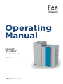
Operating Manual Easypell® 16 — 32kW ENGLISH 200013_EN 1.2 · www.easypell.com Title: Operating Manual Easypell® 16 — 32kW Article number: 200013_EN 1.2 Version valid from: 09/2015 Approved: Wohlinger Christian Author Eco Engineering 2050 GmbH A-4132 Lembach, Mühlgasse 9 Tel.: +43 (0) 72 86 / 74 50 Fax.: +43 (0) 72 86 / 74 50 – 10 E-Mail: [email protected] www.easypell.com © by Eco Engineering 2050 GmbH Subject to modifcations Contents 1 Dear Customer . . . . . . . . . . . . . . . . . . . . . . . . . . . . . . . . . . . . . . . . . . . . . . . . . . . . . . . . . . . . . . . . . . . . . . . . . . . . . . . . . . . . . . . . . . . . . . . . . . . . . . . . . . . . . . . . . . . . . . . . . . . . . . . . . . . . . . . . . . . . . . . 4 2 Types of safety warning sign . . . . . . . . . . . . . . . . . . . . . . . . . . . . . . . . . . . . . . . . . . . . . . . . . . . . . . . . . . . . . . . . . . . . . . . . . . . . . . . . . . . . . . . . . . . . . . . . . . . . . . . . . . . . . . . . . . . . . . . 5 3 Warnings and safety instructions . . . . . . . . . . . . . . . . . . . . . . . . . . . . . . . . . . . . . . . . . . . . . . . . . . . . . . . . . . . . . . . . . . . . . . . . . . . . . . . . . . . . . . . . . . . . . . . . . . . . . . . . . . . . . . . 6 3.1 Basic safety instructions ............................................................................................................................... 6 3.2 Warning signs............................................................................................................................................... 6 3.3 What to do in an emergency.........................................................................................................................7 4 Prerequisites for installing a pellet boiler . . . . . . . . . . . . . . . . . . . . . . . . . . . . . . . . . . . . . . . . . . . . . . . . . . . . . . . . . . . . . . . . . . . . . . . . . . . . . . . . . . . . . . . . . . . . . . . . . . 8 4.1 Central heating room .................................................................................................................................... 8 4.2 Safety systems ............................................................................................................................................. 9 4.3 Operation of a pellet boiler with an existing boiler ...................................................................................... 9 5 Fuel . . . . . . . . . . . . . . . . . . . . . . . . . . . . . . . . . . . . . . . . . . . . . . . . . . . . . . . . . . . . . . . . . . . . . . . . . . . . . . . . . . . . . . . . . . . . . . . . . . . . . . . . . . . . . . . . . . . . . . . . . . . . . . . . . . . . . . . . . . . . . . . . . . . . . . . . . . . . . . . . 10 5.1 Specification for high quality pellets as per EN 14961–2, class A1................................................................ 10 6 Th e Easy pe l l . . . . . . . . . . . . . . . . . . . . . . . . . . . . . . . . . . . . . . . . . . . . . . . . . . . . . . . . . . . . . . . . . . . . . . . . . . . . . . . . . . . . . . . . . . . . . . . . . . . . . . . . . . . . . . . . . . . . . . . . . . . . . . . . . . . . . . . . . . . . . . . . . . 11 7 Maintenance and servicing . . . . . . . . . . . . . . . . . . . . . . . . . . . . . . . . . . . . . . . . . . . . . . . . . . . . . . . . . . . . . . . . . . . . . . . . . . . . . . . . . . . . . . . . . . . . . . . . . . . . . . . . . . . . . . . . . . . . . . . . . 13 7.1 Maintenance ................................................................................................................................................. 13 7.2 Emptying the ash pan ................................................................................................................................. 13 7.3 Cleaning the boiler every year..................................................................................................................... 15 8 O pe r at i n g t he he at i n g sy s te m . . . . . . . . . . . . . . . . . . . . . . . . . . . . . . . . . . . . . . . . . . . . . . . . . . . . . . . . . . . . . . . . . . . . . . . . . . . . . . . . . . . . . . . . . . . . . . . . . . . . . . . . . . . . . . . . . . . . 19 8.1 Description of the control panel .................................................................................................................. 19 9 User controls and their function . . . . . . . . . . . . . . . . . . . . . . . . . . . . . . . . . . . . . . . . . . . . . . . . . . . . . . . . . . . . . . . . . . . . . . . . . . . . . . . . . . . . . . . . . . . . . . . . . . . . . . . . . . . . . . . 20 9.1 Selecting the set DHW temperature............................................................................................................22 9.1.1 Setting the time program for DHW heating ..............................................................................................23 9.1.2 Setting the time ........................................................................................................................................ 26 9.1.3 Status display ............................................................................................................................................27 9.2 Setting the boiler heating period ............................................................................................................... 28 9.2.1 Setting the time ......................................................................................................................................... 31 9.2.2 Status display ...........................................................................................................................................32 10 Malfunctions . . . . . . . . . . . . . . . . . . . . . . . . . . . . . . . . . . . . . . . . . . . . . . . . . . . . . . . . . . . . . . . . . . . . . . . . . . . . . . . . . . . . . . . . . . . . . . . . . . . . . . . . . . . . . . . . . . . . . . . . . . . . . . . . . . . . . . . . . . . . . . 33 10.1 Malfunctions - what to do .......................................................................................................................... 33 10.2 Fault texts ................................................................................................................................................. 33 10.3 Maintenance intervals ................................................................................................................................37 10.4 Repairs .......................................................................................................................................................37 10.5 Checking the central heating room and storage room .............................................................................37 Operating Manual Easypell® 16 — 32kW 4 Dear Customer 1 Dear Customer • This manual is intended to help you operate the product safely, properly and economically. • Please read this manual right through and take note of the safety warnings. • Keep all documentation supplied with this unit in a safe place for future reference. Please pass on the documentation to the new user if you decide to part with the unit at a later date. • Please contact your authorised dealer if you have any questions. 200013_EN 1.2 Types of safety warning sign 5 2 Types of safety warning sign The warning signs use the following symbols and texts. Types of safety warning sign 1. Risk of injury 2. Consequences of risk 3. Avoiding risk 1. Risk of injury: Danger - indicates a situation that could lead to death or lifethreatening injury. Warning - indicates a situation that could lead life-threatening or serious injury. Caution - indicates a situation that could lead to injury. Note - indicates a situation that could lead to property damage. 2. Consequences of risk Effects and consequences resulting from incorrect operation. 3. Avoiding risk Observing safety instructions ensures that the heating system is operated safely Operating Manual Easypell® 16 — 32kW 6 Warnings and safety instructions 3 Warnings and safety instructions Observing safety instructions ensures that the heating system is operated safely. 3.1 Basic safety instructions • Never get yourself into danger; give own safety the utmost priority. • Keep children away from the central heating room and storage room. • Observe all safety warnings on the boiler and in this user manual. • Observe all instructions relating to maintenance, servicing and cleaning. • The pellet heating system may only be installed and started up for the first time by an authorised plumber. Professional installation and start up is the prerequisite for safe and economical operation. • Never make any changes to the heating system or flue gas system. • Never close or remove safety valves. 3.2 Warning signs Risk of poisoning Make sure that the pellet boiler is supplied with sufficient combustion air. The openings in the combustion air inlet must never be partially or completely closed. Ventilation systems, central vacuum cleaning systems, extractor fans, air conditioning systems, flue gas blowers, dryers or similar equipment must never be allowed to draw air from the central heating room and cause a drop in pressure. The boiler must be connected tight to the chimney using a flue gas tube. Clean the chimney and the flue gas tube at regular intervals. The central heating room and pellet storage room must be sufficiently supplied with air and ventilated. Before entering the storage room it must be ventilated with sufficient air and the heating system switched off. Risk of electric shock Switch off the system before performing work on the boiler. Risk of explosion Never burn petrol, diesel, engine oil or other explosive materials. Never use liquids or chemicals to ignite the pellets. Switch off the heating system before filling the storage room. 200013_EN 1.2 What to do in an emergency 7 Risk of fire Do not store any flammable materials in the central heating room. Do not hang out any washing in the central heating room. Always close the boiler door. Risk of burns Do not touch the flue spigot or the flue gas tube. Do not reach into the ash chamber. Use gloves to empty the ash box. Do not clean the boiler until it has been allowed to cool down. Risk of cut injuries due to sharp edges. Use gloves for performing all work on the boiler. Damage to property Heat the pellet heating system using pellets that comply with EN 14961-2 class A1 and A2 only. Damage to property Do not use the heating system if it, or any of its components, come into contact with water. If water damage occurs, have the heating system checked by an service technician and have any damaged parts replaced. 3.3 What to do in an emergency Risk to life Never get yourself into danger; give own safety the utmost priority. What to do in the event of a fire • Switch off the heating system. • Call the fire brigade • Use approved fire extinguishers (fire protection class ABC). What to do if you smell smoke • Switch off the heating system. • Close the doors leading to living areas. • Ventilate the central heating room. Operating Manual Easypell® 16 — 32kW 8 Prerequisites for installing a pellet boiler 4 Prerequisites for installing a pellet boiler You must fulfill the following conditions before operating a fully automatic pellet boiler. 4.1 Central heating room The pellet boiler is installed in the central heating room. 1. Safety instructions for the heating room Risk of fire Do not store flammable materials or liquids in the vicinity of the pellet boiler. Do not permit unauthorised persons to enter the central heating room - children are to be kept out. Always close the boiler door. 2. Air supply and ventilation of central heating room The central heating room must be fitted with air supply and ventilation openings (at least 200cm2). Legislation in your country must be observed. 3. Combustion air supply The pellet boiler needs a supply of combustion air. Never operate the pellet boiler if the air intake openings are partially or completely closed. Contaminated combustion air can cause damage to the pellet boiler. Never store of use cleaning detergents containing chlorine, nitrobenzene or halogen in the room where the heating system is installed, if combustion air is drawn directly from the room. Do not hang out washing in the central heating room. Prevent dust from collecting at the combustion air intake to the pellet boiler. 4. Damage due to frost and humid air The central heating room must be frost-proof to ensure trouble-free operation of the heating system. The temperature of the central heating room must not fall below –3°C and must not exceed +30°C. The air humidity in the central heating room must not exceed 70%. 5. Danger for animals Make sure that household pets and other small animals cannot enter the central heating room. Fit mesh over any openings. 6. Flooding If there is a risk of flooding, switch off the pellet boiler in good time and disconnect from the power supply before water enters the central heating room. You must have all components that come into contact with water replaced, before you start up the pellet boiler again. 7. Cleaning Clean the flue gas tube and chimney regularly. Oxidation of chimney Do not use metal brushes to clean chimneys made of stainless steel. Legislation in your country must be observed. 200013_EN 1.2 Safety systems 9 4.2 Safety systems The following safety measures are the prerequisite for safe operation of your system. Emergency stop switch Every heating system must be able to be switched off with an Emergency Stop switch. The Emergency Stop switch must be inside the central heating room. Safety valve The hydraulic system must be equipped with a safety valve. This valve opens when the pressure inside the heating system increases to max. 3 bar. The safety valve must: –be installed at the highest point of the boiler, –must not be locked, –and must be within 1 metre of the boiler. Safety temperature sensor The pellet boiler is equipped with a safety temperature sensor. This is located on the pellet boiler. If the boiler temperature exceeds 95°C then the heating system switches off. Expansion tank All heating systems must be equipped with a pressurised expansion tank. The plumber or heating system installer must dimension the expansion tanks according to the dimensions of the hydraulic system. Starting up Starting up for the first time has to be performed only by an authorized service technician. 4.3 Operation of a pellet boiler with an existing boiler There are different regulations in the different European countries. Please mind the prescription of your country. Operating Manual Easypell® 16 — 32kW 10 Fuel 5 Fuel Wood pellets are natural wood (dried sawdust or waste from machining) that has been formed into pellets under high pressure. They have a very low moisture content and very high calorific value. The manufacture of wood pellets is regulated by European standard EN 14961–2. 5.1 Specification for high quality pellets as per EN 14961–2, class A1 Calorific value 4,6 — 5,3 kWh/kg 16,5 — 19 MJ/kg Loose density min. 600 kg/m3 Water content max. 10% Ash content max. 0.7% Ash melting point at least 1200°C Length max. 40 mm Diameter 6 – 8 mm Fine material max. 1% Contents 100% natural wood The he a t i ng sy s t e m i s s uit a ble o nl y f o r pe lle t s of natural wood that comply with standard EN 14961–2 class A1 with a diameter of 6 – 8 mm. Using non-pelletised fuels or pellets that are not manufactured from natural wood will lead to the warranty becoming void and will cause damage to the pellet boiler and the chimney. Use only quality pellets from Austrian standard approved, DINplus or ENplus approved manufacturers. For more information on fuels, please visit the website: www.oekofen.com 200013_EN 1.2 The Easypell 11 6 The Easypell Easypell types and power ratings Eco Engineering offers the Easypell with the following power ratings: 16, 20, 25 and 32kW. Note: Refer to the data plate for the power rating of your Easypell. The data plate is located on the rear side of the boiler. Here you find the type designation, manufacturer's serial number and year of build. Key components of the Easypell 1 Boiler (heat exchanger) 3 Boiler controller 2 Burner 4 Pellet hopper Operating Manual Easypell® 16 — 32kW 12 The Easypell 1 Burner plate 7 Suction fan 2 Flame tube 8 Anti-blowback system 3 Heat exchanger 9 Burner auger 4 Boiler water 10 Electronic ignition 5 Boiler insulation 11 Combustion chamber sensor 6 Combustion chamber cover 12 Ash box 200013_EN 1.2 Maintenance and servicing 13 7 Maintenance and servicing Regular checks of the pellet heating system are a prerequisite for reliable, efficient and environment-friendly operation. 7.1 Maintenance Maintenance, boiler cleaning and cleaning of flue gas connection are necessary at least once a year. Pellets which produces tendentially more slagging (ash melting point <1300 ° C) and pellets with higher bulk density (> 650kg) leads to additional cleaning of the burner plate at regular intervals. 7.2 Emptying the ash pan Risk of burns Use gloves. Do not touch the boiler vessel. Risk of fire Do not empty ash into a flammable container. Do not empty ash onto flammable floors or materials. Do not dispose of ash until it has completely cooled down. Note: Check the level of the ash box and empty it at regularl intervals (at least every 2 weeks). Operating Manual Easypell® 16 — 32kW 14 200013_EN 1.2 Emptying the ash pan Cleaning the boiler every year 15 7.3 Cleaning the boiler every year Boiler cleaning must be carried out once every heating season. Risk of burns Do not clean the boiler until it has been allowed to cool down. Switch off the heating system at least 6 hours before opening the boiler. Switch off the main switch before starting any maintenance work on the system. Risk of cut injuries due to sharp edges Use gloves. Operating Manual Easypell® 16 — 32kW 16 Procedure for cleaning the boiler 200013_EN 1.2 Cleaning the boiler every year Cleaning the boiler every year 17 Reduction in boiler performance and damage to pellet boiler due to blockages in the air inlet Clean the air intakes, the burner plate and the flame tube. Operating Manual Easypell® 16 — 32kW 18 Cleaning the Induced draft blower: 200013_EN 1.2 Cleaning the boiler every year Operating the heating system 19 8 Operating the heating system Damage caused do to incorrect operation or incorrect settings. Only trained operators may use the heating system. Make sure no unauthorised persons enter the central heating room. Keep children away from the central heating room and storage room. Fire risk Keep the ash removal door closed while the boiler is in operation. 8.1 Description of the control panel The control panel is located in the boiler front cover. 1 Safety temperature sensor Switches the heating system off, if the boiler temperature reaches 95°C. 2 Main switch Switches off the heating system (both poles) including the power supply to the control panel. 3 User control unit Operates the boiler controller and the heating controller. Operating Manual Easypell® 16 — 32kW 20 User controls and their function 9 User controls and their function Navigation-icons Iconview Description Use the up arrow to return to the previous menu screen. Use the down arrow to arrive at the next menu screen. When this symbol is displayed, the set value can be changed. When this function is selected, the value can be changed by pressing the arrow keys. When this function is selected, you leave the menu without saving the changed value. Icons System status Iconview Description Run down time Heating full power Container cover is open OFF Ignition Boiler cleaning Note: This message appears when the container cover has been open for longer than 20 seconds. Warning 200013_EN 1.2 User controls and their function 21 After switching on, the boiler starts (after approx. 10 seconds). The fire protection device is opened. This symbol appears on the display while the fire protection device is being opened (approx. 2 minutes). After the fire protection device has been opened, the ignition process starts and the symbol for ignition is displayed. On completion of the ignition process (can last up to 15 minutes), the symbol for heating at full power appears. The boiler is now heating at full power. – button Operating Manual Easypell® 16 — 32kW 22 Selecting the set DHW temperature The current boiler temperature is displayed. – button 9.1 Selecting the set DHW temperature Note: This function is only available if a DHW sensor is connected to the boiler controller. Please also refer to the installation manual, chapter 13, "Controller for heating and hot water". The current DHW temperature is displayed. – button The set DHW temperature is displayed. Factory setting = 50° C 200013_EN 1.2 Setting the time program for DHW heating 23 The set DHW temperature can be changed as follows: – button The value can be raised or lowered by pressing the keys / . – button = save value The stored value is displayed. – button 9.1.1 Setting the time program for DHW heating 1. Heating period 1 2. Heating period 2 Operating Manual Easypell® 16 — 32kW 24 Setting the time program for DHW heating – button Cursor at the hour. – button The value can be set by pressing the keys – button = save value Cursor jumps to the minute. Other values (minutes and hours) are set as described above. Note: The set heating period still needs to be activated. 200013_EN 1.2 / . Setting the time program for DHW heating 25 – button Cursor at the symbol . – button button = Activate the set heating periods. The symbol shows that the heating periods have been activated and saved. Operating Manual Easypell® 16 — 32kW 26 Setting the time – button 9.1.2 Setting the time The current time is displayed. Note: The time is set in the same way as the heating periods! – button 200013_EN 1.2 Status display 27 9 . 1 . 3 S t a t u s d i s p l ay The current status is displayed. No settings can be entered. This display is for information only. Pressing the button repeatedly returns you to the start screen. Status display symbols: Display Description DHW priority active (heating circuit demand is subordinate). Pump output active. Minimum boiler temperature (pump release) has not been reached. Time program active. Burner demand via burner contact / thermostat. Warning Operating Manual Easypell® 16 — 32kW 28 Setting the boiler heating period 9.2 Setting the boiler heating period Note: This function is only available if an external heating controller is used and no DHW sensor is connected to the boiler controller. Please also refer to the installation manual, chapter 13, "Controller for heating and hot water" If heating periods are programmed, the boiler runs at the set times. During these periods, burner requests from the external controller (terminal 7/8) are ignored. Outside the programmed heating periods, burner demand from the external controller (terminal 7/8) is active again. Note: Programming of heating periods is NOT advisable if an external controller is used! – button Cursor at the hour. – button 200013_EN 1.2 Setting the boiler heating period 29 The value can be set by pressing the keys / . – button = save value Cursor jumps to the minute. Other values (minutes and hours) are set as described above. Note: The set heating period still needs to be activated. Operating Manual Easypell® 16 — 32kW 30 Setting the boiler heating period – button Cursor at the symbol . – button button = Activate the set heating periods. The symbol shows that the heating periods have been activated and saved. 200013_EN 1.2 Setting the time 31 – button 9.2.1 Setting the time The current time is displayed. Note: The time is set in the same way as the heating periods! – button Operating Manual Easypell® 16 — 32kW 32 Status display 9 . 2 . 2 S t a t u s d i s p l ay The current status is displayed. No settings can be entered. This display is for information only. Pressing the button repeatedly returns you to the start screen. Status display symbols: Display Description Pump output active. Minimum boiler temperature (pump release) has not been reached. Time program active. Burner demand via burner contact / thermostat. Warning 200013_EN 1.2 33 Malfunctions 1 0 Malfunctions 10.1 Malfunctions - what to do Follow the sequence described for handling malfunctions. • The heating system switches off automatically if a malfunction occurs. • The control unit display shows a malfunction alarm text. • You have to rectify the cause of the malfunction. • After eliminating the underlying causes, you can restart the boiler. 10.2 Fault texts The fault text displayed on the screen provides information on the type and status of the malfunction as well as help for troubleshooting. 1. Warning symbol 2. Error code 3. Error symbol Note: The system restarts automatically when the cause has been eliminated. Overview of malfunction alarm texts: Display: Error code: 0 Description: Boiler sensor fracture, measuring circuit from boiler sensor is open Cause and Remedy: sensor not connected ڃconnect sensor at input sensor defect ڃmeasure sensor (approx. 2kˑ at 25° C) replace if required sensor cable defect ڃreplace sensor sensor temperature too high ڃsensor temperature above measuring range (1100° C) Description: Boiler sensor short circuit, measuring circuit from boiler sensor is shorted out Cause and Remedy: sensor defect ڃmeasure sensor (approx. 2kˑ at 25° C) replace if required sensor cable defect ڃreplace sensor sensor temperature too low ڃsensor temperature below measuring range (10° C) Operating Manual Easypell® 16 — 32kW 34 Fault texts Display: Error code: 1, 2, 3 Description: Combustion chamber sensor fracture, measuring circuit from combustion chamber sensor is open Cause and Remedy: sensor not connected ڃconnect sensor at input sensor defect ڃMeasure sensor (approx. 5mV at 125° C) replace if required sensor cable defect ڃreplace sensor sensor temperature too high ڃsensor temperature above measuring range (1100° C) Description: Combustion chamber sensor short-circuit, measuring circuit from combustion chamber sensor is shorted out Cause and Remedy: sensor defect ڃMeasure sensor (approx. 5mV at 125° C) replace if required sensor cable defect ڃreplace sensor sensor temperature too low ڃsensor temperature below measuring range (10° C) sensor polarity incorrect ڃexchange + and – connections Display: Error code: 4 Description: Negative draft input open, measuring circuit from negative draft measurement open Cause and Remedy: signal incorrect ڃcheck polarity and signal (0-10V) signal cable defect ڃreplace sensor signal too low ڃsignal below 0V combustion chamber leak ڃcheck closure of boiler door Error code: 5 Description: Negative draft input short-circuit, measuring circuit from negative draft measurement is shorted out Cause and Remedy: signal incorrect ڃcheck polarity and signal (0-10V) signal cable defect ڃreplace sensor signal too high ڃsignal above 10V Error code: 6 Description: Negative draft pressure in boiler is not achieved Cause and Remedy: negative draft tube disconnected 200013_EN 1.2 ڃconnect up negative draft tube Fault texts 35 negative draft does not change ڃCheck negative draft tube for leaks. Check flue gas tube for blockage. Negative draft pressure too low ڃClose boiler door, check tube to negative draft sensor, check whether boiler flue gas outlet is clear, check whether condensation heat exchanger is clear. Make sure flue gas fan is running. Display: Error code: 7 Description: Safety temperature limiter has tripped Cause and Remedy: safety temperature limiter unplugged ڃconnect up safety temperature limiter and check cable connections safety temperature limiter has tripped ڃcheck boiler controller safety temperature limiter defect ڃallow boiler to cool and reset alarm Display: Error code: 8, 9 Description: Flue gas minimum temperature not reached during ignition phase Cause and Remedy: no pellets available ڃfill up with pellets ignition electrode defect ڃcheck ignition electrode (approx. 200ˑ) replace if required ignition nozzle blocked ڃclean burner plate and ignition tube flue gas sensor contaminated ڃclean flue gas sensor and flue gas tube flue gas sensor is not in flue gas tube ڃinsert flue gas sensor into flue gas tube Display: Error code: 10 Description: Flame return gate open fault. Cause and Remedy: flame return gate unplugged ڃConnect up flame return gate and check cable connections Flame return gate does not reach OPEN limit switch ڃcheck ball valve to see if it is jammed no signal although open ڃcheck cables and flame return gate Error code: 11 Operating Manual Easypell® 16 — 32kW 36 Fault texts Description: Flame return gate closed fault. Cause and Remedy: flame return gate unplugged ڃConnect up flame return gate and check cable connections Flame return gate does not reach CLOSE limit switch ڃcheck whether ball valve is jammed, check ball valve throughway to see if foreign objects are preventing it from closing no signal although closed ڃcheck cables and flame return gate Error code: 12 Description: Both flame return gate limit switches are closed at the same time Cause and Remedy: both limit switches activated ڃcheck flame return gate, check cables, check connectors Display: Error code: 14 Description: Container cover open Cause and Remedy: Cover open ڃclose cover End-switch defect ڃreplace end-switch Display: Error code: 15 Description: DHW sensor fracture, measuring circuit from DHW sensor is open Cause and Remedy: sensor not connected ڃconnect sensor at input sensor defect ڃmeasure sensor (approx. 2kˑ at 25° C) replace if required sensor cable defect ڃreplace sensor sensor temperature too high ڃsensor temperature above measuring range (1100° C) Description: DHW sensor short circuit, measuring circuit from boiler sensor is shorted out Cause and Remedy: sensor defect ڃmeasure sensor (approx. 2kˑ at 25° C) replace if required sensor cable defect ڃreplace sensor sensor temperature too low ڃsensor temperature below measuring range (10° C) 200013_EN 1.2 Maintenance intervals 37 10.3 Maintenance intervals Eco Engineering recommends regular/annual maintenance by an Eco Engineering service technician or an authorized partner. The volume of maintenance beyond the cleaning of the boiler also contains for example a check of equipment, components and safety systems, if necessary the adaption of adjustments, trial operation and production of a maintenance report. In some European countries there are legal obligations applying to maintenance intervals and emission measuring. Contact your authorised dealer. Eco Engineering recommends taking out a maintenance contract with your service technician. 10.4 Repairs Only authorised specialists may carry our repair work on this system. Use original Eco Engineering spare parts only. Not using original Eco Engineering spare parts will cause the warranty to become void. 10.5 Checking the central heating room and storage room Checking the pellet heating system regularly prevents malfunctions and unexpected failure of the heating system. Central heating room Make sure that no flammable materials are stored in the central heating room. Make sure that no washing is hanging in the central heating room. Check the display at the control panel for malfunction messages. Check the flue gas tube and chimney. Let them clean regularly (at least once per year). Storage room Risk of suffocation Ventilate the pellet storage room sufficiently before entering. Switch off the heating system before entering. Check the level of pellets in the pellet storage room or fabric tank and order more pellets in good time. Operating Manual Easypell® 16 — 32kW Author Eco Engineering 2050 GmbH A-4132 Lembach, Mühlgasse 9 Tel.: +43 (0) 72 86 / 74 50 Fax.: +43 (0) 72 86 / 74 50 – 10 E-Mail: [email protected] www.easypell.com © by Eco Engineering 2050 GmbH Subject to modifcations