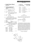
1
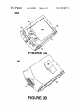
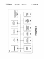
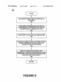
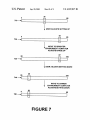
US006947017B1
(12) United States Patent
(10) Patent N0.:
Gettemy
(54)
(75)
(45) Date of Patent:
Sep. 20, 2005
DYNAMIC BRIGHTNESS RANGE FOR
5,933,130 A *
PORTABLE COMPUTER DISPLAYS BASED
5,952,992 A *
9/1999 Helms
ON AMBIENT CONDITIONS
6,094,185 A *
7/2000 Shirritf ..................... .. 345/102
Inventor:
Shawn R. Gettemy, San Jose, CA (US)
345/102
Primary Examiner—Chanh Nguyen
(73) Asslgnee: Palm’ Inc'> Sunnyvale> CA (Us)
Notice:
8/1999 Wagner .................... .. 345/690
* cued by exammer
_
(*)
US 6,947,017 B1
(74) Attorney, Agent, or Firm—Wagner, Murabito & Hao
Subject to any disclaimer, the term of this
patent is extended or adjusted under 35
LLP
(57)
ABSTRACT
U.S.C. 154(b) by 151 days.
(21) Appl' NO': 09/942’437
22
Fl (12
A
1e
A portable computer system that comprises dynamically
_ 29 2001
adjustable brightness range settings and brightness control
u
or prov1 Ing Improve user rea a 1 Ity an pro onge
(51)
(52)
Int. Cl.7 .............................................. .. G09G 3/28
US. Cl. ....................................... .. 345/63; 345/690
(58)
Field of Search
345/63 77 204
"""""""""""""" "
’
’
ditions or the user can perform the changes. The brightness
’
level of the display changes according to a user selected
345/102’ 207’ 581’ 589’ 690’ 348/602’ 603
setting Within the range selected. The time required to
(56)
_
com
ponent lifetime of the display Screen‘ The main processor
can Change the range Settings based on ambient light Con
References Cited
implement the brightness change can be set to a value Which
can be con?gured by the user.
U.S. PATENT DOCUMENTS
5,760,760 A *
6/1998 Helms ...................... .. 345/102
21 Claims, 8 Drawing Sheets
60
|
ENTER
I
II
LIGHT SENSOR SENDS LIGHT INFORMATION TO
PROCESSOR
m
I
PROCESSOR DETERMINES NEED FOR RANGE
CHANGE BASED ON CONFIGURATION DATA AND
CHANGES RANGE TO DESIGNATED LEVEL
QQ
I
USER PRESET SLIDER POSI11ON REMAINS SAME
m
V
SETI'ING OF SLIDER POSI'HON CHANGES FOR NEW
RANGE, COMMENSURATE WITH ITS RELATIVE
POSITION WITHIN THE NEW RANGE
m
V
DISPLAY CONTROLLER CHANGES LIGHT
TRANSMI'I'I'ED OR EMI'ITED WITHIN DISPLAY DEVICE
ACCORDING TO SETTING WITHIN NEW RANGE AND
OVER SPECIFIED TIME INTERVAL
650
I
RETURN
I
U.S. Patent
Sep. 20,2005
Sheet 1 of 8
US 6,947,017 B1
DISPLAY SCREEN
120
70$
REFLECTOR
\
130 q
/
’
EXTERNAL LIGHT SOURCE
103
II
REFLECTIVE
FIGURE 1A
(PRIOR ART)
EXTERNAL LIGHT SOURCE
103 w
DISPLAY SCREEN
[U
_
150
\I/
\gi
/
\
l\
[I4———-——>
BACKLIGHT
140
[I
HOLE IN RELECTOR
q
%
/
r
_
[I
\ REFLECTCR
TRANSFLECTIVE
16°
FIGURE 18
(PRIOR ART)
17o
U.S. Patent
Sep. 20,2005
Sheet 2 of 8
US 6,947,017 B1
DISPLAY SCREEN
101
BACKLIG HT
\
/
A0:
+
EXTERNAL LIGHT SOURCE
103
TRANSMISSIVE
FIGURE 1C
(PRIOR ART)
DISPLAY SCREEN WITH LIGHT
EXTERNAL :‘(gHT SOURCE
EMITI'ING ELEMENT
12L
\\ I 2'
i729>
EMISSIVE
FIGURE1D
(PRIOR ART)
U.S. Patent
Sep. 20,2005
Sheet 3 of 8
FIGURE 28
US 6,947,017 B1
U.S. Patent
Sep. 20,2005
Sheet 4 of 8
US 6,947,017 B1
mmDQE
U.S. Patent
Sep. 20,2005
Sheet 5 of 8
592
FIGURE 4
US 6,947,017 B1
U.S. Patent
5
510
Sep. 20,2005
Sheet 6 of 8
_
US 6,947,017 B1
65
l
35
20
520
—
100
I
60
2O
530
__
I
.._l
160
FIGURE 5
300
U.S. Patent
Sep. 20,2005
Sheet 7 of 8
US 6,947,017 B1
00
‘
ENTER
I
II
LIGHT SENSOR SENDS LIGHT INFORMATION TO
PROCESSOR
m
V
PROCESSOR DETERMINES NEED FOR RANGE
CHANGE BASED ON CONFIGURATION DATA AND
CHANGES RANGE TO DESIGNATED LEVEL
E‘!
II
USER PRESET SLIDER POSITION REMAINS SAME
5%
II
SE'I'I'ING OF SLIDER POSITION CHANGES FOR NEW
RANGE, COMMENSURATE WITH ITS RELATIVE
POSITION WITHIN THE NEW RANGE
m
l
DISPLAY CONTROLLER CHANGES LIGHT
TRANSMITTED OR EMI'ITED WITHIN DISPLAY DEVICE
ACCORDING TO SETTING WITHIN NEW RANGE AND
OVER SPECIFIED TIME INTERVAL
650
l
RETU RN
FIGURE 6
I
U.S. Patent
Sep. 20, 2005
Sheet 8 0f 8
US 6,947,017 B1
35
5
-—
710
65
l
i USER ADJUSTS SETTING UP
55
5
—
720
65
l
i MOVE TO BRIGHTER
ENVIRONMENT COMPUTER
ADJUSTS RANGE UP
87
20
—
730
100
l
_l
l USER ADJUSTS SETTING DOWN
40
20
740
100
l
MOVE TO DARKER
ENVIRONMENT COMPUTER
ADJUSTS SETTING DOWN
2O
5
—
65
750
FIGURE 7
US 6,947,017 B1
1
2
DYNAMIC BRIGHTNESS RANGE FOR
PORTABLE COMPUTER DISPLAYS BASED
ON AMBIENT CONDITIONS
external light competes With the emitted light of the emis
sive display screen. Emissive and transmissive displays can
not be vieWed very Well in the sun unless the brightness is
BACKGROUND OF THE INVENTION
turned very high. High brightness can reduce the life of the
display and cause poor battery life performance.
One conventional approach to adjusting the brightness of
the display With respect to the ambient light is to include
1. Field of the Invention
The present invention relates to the ?eld of portable
computer systems, such as personal digital assistants or
photo detectors to adjust the brightness or to turn a backlight
on or off. In this approach there is a ?xed brightness range
Which does not alWays provide a comfortable vieWing
experience for the user.
Another conventional approach gives the user manual
palmtop computer systems. Speci?cally, embodiments of
the present invention relate to a portable computer system
equipped With a dynamic brightness range control to maxi
miZe readability in various ambient lighting conditions and
to prolong the lifetime of the display, the light and the
battery.
15
2. Related Art
control of the amount of light being produced for the
transmissive and emissive display screens. This approach is
satisfactory for conscientious users Who regularly monitor
the brightness settings and manually adjust them accord
A portable computer system, such as a personal digital
ingly. HoWever, as is often the case, the user can set the
assistant (PDA) or palmtop, is an electronic device that is
small enough to be held in the hand of a user and is thus
display screen for maximum brightness so that the display is
more easily read in sunlight, thereby not having to make
frequent adjustments. In the case of the transmissive display,
this frequently results in less than optimal battery and
backlight lifetime experience. In the case of the emissive
display, in addition to a reduced battery experience, the
emissive material, usually either an organic or polymer, has
“palm-sized.” By virtue of their siZe, portable computer
systems are lightWeight and so are exceptionally portable
and convenient. These portable computer systems are gen
erally contained in a housing constructed of conventional
materials such as rigid plastics or metals.
Portable computer systems are generally poWered using
either rechargeable or disposable batteries. Because of the
desire to reduce the siZe and Weight of the portable computer
system to the extent practical, smaller batteries are used.
25
a ?nite lifetime. This lifetime becomes severely shortened if
the display screen is alWays turned to the maximum setting.
SUMMARY OF THE INVENTION
Thus, poWer conservation in portable computer systems is
an important consideration in order to reduce the frequency
at Which the batteries either need to be recharged or
Accordingly, What is needed is a system and/or method
that can provide a display Which is readable in various
replaced. Consequently, the portable computer system is
ambient lighting conditions for a various types of display
placed into a loW poWer mode (e.g., a sleep mode or deep
screens and Which Will provide the user With a pleasant
sleep mode) When it is not actively performing a particular
battery experience and prolong the life of materials that
Would be harmed by excessive brightness. The present
invention provides these advantages and others not speci?
function or operation.
There are many other similar types of intelligent devices
(having a processor and a memory, for example) that are
cally mentioned above but described in the sections to
folloW.
A portable computer system or electronic device which
siZed in the range of laptops and palmtops, but have different
capabilities and applications. Video game systems, cell
phones, pagers and other such devices are examples of other
types of portable or hand-held systems and devices in
includes a lighted display device With dynamically adjust
40
common use.
These systems, and others like them, have in common
implements the adjustment for the range settings based on
prestored range con?guration data and an ambient light
some type of screen for displaying images as part of a user
interface. Many different kinds of screens can be used, such
information signal from the light sensor. In one embodiment
as liquid crystal displays, and ?eld emission displays or
other types of ?at screen displays. Refer to FIGS. 1A—1D for
45
examples of types of display screens.
of the present invention, the lighted display device is trans
missive While in another embodiment the lighted display
device is emissive.
In one embodiment of the present invention, the portable
As illustrated in FIG. 1A, a re?ective display is shoWn
including a display screen 110 having a re?ective surface
130 so that the display is enhanced in bright external light
103 such as sunlight but requires a front light 120 in darker
computer system or electronic device further includes a user
adjustment for adjusting the light setting Within the proces
sor-implemented range setting for the display device. In
environments. The display screen 150 of FIG. 1B can also
be trans?ective. It has a re?ector 160 to re?ect light from an
external source 103. This re?ector 160 comprises holes 170
through Which light from the backlight 140 can pass for
lighting darker environments. FIG. 1C illustrates another
type of display screen Which is transmissive. The transmis
able range settings, a processor, a light sensor and a display
controller is disclosed. In one embodiment, the processor
another embodiment of the present invention, the user can
change and control the con?guration of the dynamically
adjustable range settings. The dynamically adjustable range
55
settings, in still another embodiment, can be overridden by
sive display screen 101 has no re?ector so it requires a
the user, enabling the user to control the brightness of the
display screen. In yet another embodiment, the relative
backlight 102. When bright external light, such as sunlight,
is present, this external light 103 competes With the back
position of the user-adjustable setting Within a given range
remains unchanged When the range setting changes.
light and it becomes dif?cult to see the transmissive display
screen. Another non-re?ective type of display is the emis
sive display screen as illustrated in FIG. 1D. Among the
family of emissive display screens one ?nds Organic Light
In one embodiment of the present invention, the display
controller implements an adjustment to the brightness of the
Emitting Diode (OLED), Organic Electro-Luminescent
(OEL), Polymer Light Emitting Diode (Poly LED), and
ment this brightness adjustment is immediate While, in
Field Emission Displays
The emissive screen 190
contains light emitting elements and, therefore, requires no
separate backlight. As With the transmissive screens, bright
display device according to the implemented range setting
and user-adjustable setting Within said range. In one embodi
another embodiment, the brightness adjustment occurs over
65
a longer time period, the time period being user-adjustable.
In yet another embodiment, the time period for the bright
ness adjustment to occur is a ?xed value.
US 6,947,017 B1
4
3
Other features and advantages of the invention Will
stored, transferred, combined, compared, and otherWise
become apparent from the following detailed description,
taken in conjunction With the accompanying drawings,
illustrating by Way of example the principles of the inven
manipulated in a computer system. It has proven convenient
at times, principally for reasons of common usage, to refer
to these signals as bits, values, elements, symbols, charac
tion.
ters, terms, numbers, or the like.
It should be borne in mind, hoWever, that all of these and
similar terms are to be associated With the appropriate
BRIEF DESCRIPTION OF THE DRAWINGS
physical quantities and are merely convenient labels applied
The accompanying draWings, Which are incorporated in
and form a part of this speci?cation, illustrate embodiments
of the invention and, together With the description, serve to
to these quantities. Unless speci?cally stated otherWise, as
10
explain the principles of the invention:
the folloWing terms refer to the actions and processes of a
FIG. 1A illustrates a re?ective display screen for use With
a portable computer system or electronic device.
FIG. 1B illustrates a trans?ective display screen for use
With a portable computer system or electronic device.
15
FIG. 1C illustrates a transmissive display screen for use
With a portable computer system or electronic device.
a portable computer system or electronic device.
FIG. 2A is a topside perspective vieW of a portable
computer system in accordance With one embodiment of the
Exemplary Palmtop Platform
present invention.
The embodiments of the present invention may be prac
ticed on any electronic device having a display screen, e.g.,
a pager, a cell phone, a remote control device, or a mobile
25
FIG. 2A is a perspective illustration of the top face 200a
of one embodiment of the portable computer system 300 of
the present invention. The top face 200a contains a display
playing the range and the user-controllable brightness
adjustment according to one embodiment of the present
screen 105 surrounded by has a top layer touch sensor able
to register contact betWeen the screen and the tip of the
stylus 80. The stylus 80 can be of any material to make
contact With the screen 105. The top face 200a also contains
one or more dedicated and/or programmable buttons 75 for
invention.
FIG. 5 illustrates one embodiment of the present inven
tion, shoWing examples of computer generated and on
screen displayed dynamically adjustable range settings for
various ambient light conditions, With corresponding
35
FIG. 6 is a block diagram illustrating the process of
according to one embodiment of the present invention.
40
DETAILED DESCRIPTION OF THE
INVENTION
In the folloWing detailed description of the present inven
45
tion, numerous speci?c details are set forth in order to
provide a thorough understanding of the present invention.
HoWever, it Will be recogniZed by one skilled in the art that
the present invention may be practiced Without these speci?c
details or With equivalents thereof. In other instances, Well
knoWn methods, procedures, components, and circuits have
not been described in detail as not to unnecessarily obscure
aspects of the present invention.
Notation and Nomenclature
Some portions of the detailed descriptions, Which folloW,
(e.g., process 600 of FIG. 6) are presented in terms of
selecting information and causing the computer system to
implement functions. The on/off button 95 is also shoWn.
FIG. 2A also illustrates a handWriting recognition area of
the top layer touch sensor or “digitizer” containing tWo
changing the range setting and the brightness of the display
FIG. 7 illustrates changing of brightness settings by a user
and changing of brightness ranges by a processor.
computer system. The discussion that folloWs illustrates one
exemplary embodiment being a hand held computer system.
FIG. 4 is a perspective vieW of the display screen dis
dynamically changing brightness settings.
computer system or similar electronic computing device.
These devices manipulate and transform data that is repre
sented as physical (electronic) quantities Within the com
puter system’s registers and memories or other such infor
mation storage, transmission or display devices. The
aforementioned terms include, but are not limited to, “scan
ning” or “determining” or “generating” or “identifying” or
“comparing” or “sorting” or “selecting” or “implementing”
or “displaying” or “initiating” or the like.
FIG. 1D illustrates an emissive display screen for use With
FIG. 2B is a bottom side perspective vieW of the portable
computer system of FIG. 2A.
FIG. 3 is a block diagram of an exemplary portable
computer system upon Which embodiments of the present
invention may be practiced.
apparent from the folloWing discussions, it is appreciated
that throughout the present invention, discussions utiliZing
55
regions 106a and 106b. Region 106a is for the draWing of
alphabetic characters therein (and not for numeric charac
ters) for automatic recognition, and region 106b is for the
draWing of numeric characters therein (and not for alpha
betic characters) for automatic recognition. The stylus 80 is
used for stroking a character Within one of the regions 106a
and 106b. The stroke information is then fed to an internal
processor for automatic character recognition. Once char
acters are recogniZed, they are typically displayed on the
screen 105 for veri?cation and/or modi?cation.
FIG. 2B illustrates the bottom side 200b of one embodi
ment of the palmtop computer system that can be used in
accordance With various embodiments of the present inven
tion. An extendible antenna 85 is shoWn, and also a battery
storage compartment door 90 is shoWn. A serial port 180 is
also shoWn.
FIG. 3 is a block diagram of one embodiment of a portable
computer system 300 upon Which embodiments of the
present invention may be implemented. Portable computer
procedures, steps, logic blocks, processing, and other sym
system 300 is also often referred to as a PDA, a PID, a
bolic representations of operations on data bits that can be
palmtop, or a hand-held computer system.
Portable computer system 300 includes an address/data
performed on computer memory. These descriptions and
representations are the means used by those skilled in the
data processing arts to most effectively convey the substance
of their Work to others skilled in the art. A procedure,
computer executed step, logic block, process, etc., is here,
and generally, conceived to be a self-consistent sequence of
steps or instructions leading to a desired result. The steps are
those requiring physical manipulations of physical quanti
ties. Usually, though not necessarily, these quantities take
the form of electrical or magnetic signals capable of being
65
bus 305 for communicating information, a central (main)
processor 310 coupled With the bus 305 for processing
information and instructions, a volatile memory 320 (e.g.,
random access memory, RAM) coupled With the bus 305 for
storing information and instructions for the main processor
310, and a non-volatile memory 330 (e.g., read only
memory, ROM) coupled With the bus 305 for storing static
information and instructions for the main processor 310.
Portable computer system 300 also includes an optional data
US 6,947,017 B1
5
6
storage device 340 coupled With the bus 305 for storing
Which the user last set it. Refer to FIG. 4 for an illustration
information and instructions. Device 340 can be removable.
Portable computer system 300 also contains a display device
105 coupled to the bus 305 for displaying information to the
of the slider 430, the loW range setting 410, and the high
range setting 420.
In step 640 of FIG. 6, the processor interprets the bright
computer user.
ness setting of said slider position 430 relative to the loW
range setting 410 and the high range setting 420. For
eXample, referring to 510 of FIG. 5, the midpoint setting for
In the present embodiment, portable computer system 300
of FIG. 3 includes communication circuitry 350 coupled to
bus 305. In one embodiment, communication circuitry 350
is a universal asynchronous receiver-transmitter (UART)
module that provides the receiving and transmitting circuits
required for serial communication for the serial port 180.
Also included in computer system 300 is an optional
alphanumeric input device 106 that, in one implementation,
a brightness range of 5 nits to 65 nits is 35 nits, Where the
same midpoint setting for a brightness range of 20 nits to
10
300 nits, as shoWn on 530 of FIG. 5 is 160 nits.
Still referring to FIG. 6, the processor sends a signal to the
display controller Which, in step 650, implements the appro
priate change to the brightness level over a time period
speci?ed by stored display con?guration data so that bright
is a handWriting recognition pad (“digitizer”). Alphanumeric
input device 106 can communicate information and com 15 ness changes are not abrupt and therefore are transparent to
the user.
mand selections to main processor 310 via bus 305. In one
At any time, the user can display the currently selected
implementation, alphanumeric input device 106 is a touch
screen device. Alphanumeric input device 460 is capable of
registering a position Where a stylus element (not shoWn)
range setting and move the slider up or doWn to increase or
makes contact.
processor Will dynamically adjust the range When the ambi
decrease the brightness setting of the display. The computer
ent light changes suf?ciently, keeping the brightness level
Portable computer system 300 also includes an optional
commensurate With the slider position last selected relative
cursor control or directing device (on-screen cursor control
to the neW range setting. FIG. 7 illustrates user adjustments
380) coupled to bus 305 for communicating user input
to the brightness settings and computer processor adjust
information and command selections to main processor 310.
ments to the brightness range.
In one implementation, on-screen cursor control device 380
is a touch screen device incorporated With display device
105. On-screen cursor control device 380 is capable of
registering a position on display device 105 Where a stylus
element makes contact. The display device 105 utiliZed With
25
setting up to a brightness of 55 nits, as shoWn in step 720.
When the user goes into a brighter environment, the com
puter processor adjusts the range to that of 20 nits to 100
portable computer system 300 may utiliZe a re?ective,
trans?ective, transmissive or emissive type display.
In one embodiment, portable computer system 300
nits, as illustrated by step 730. The brightness setting for the
previously set slider position is noW 87 nits. The user noW
adjusts the setting doWn to a preferred level, e.g., 40 nits as
includes one or more light sensors 390 to detect the ambient
shoWn in step 740. NoW, When the user enters a darker
light and provide a signal to the main processor 310 for
determining When to implement a change in brightness
range. Display controller 370 implements display control
35
commands from the main processor 310 such as increasing
or decreasing the brightness of the display device 105.
40
set slider position is noW 20 nits.
The present invention has been described in the context of
for eXample, a housing and a processor, such that the device
performs certain functions on behalf of the processor. Fur
thermore, it is appreciated that these certain functions may
include functions other than those associated With navigat
interface. In this embodiment the user adjusts the on-screen
displayed brightness setting betWeen the loW level 410 of the
range and the high level 420 of the range by moving the
slider 430 to the right for an increase in brightness or to the
left for a decrease in brightness.
environment, the computer processor adjusts the range
doWn, as shoWn in step 750, so the setting for the previously
a portable computer system; hoWever, the present invention
may also be implemented in other types of devices having,
Referring noW to FIG. 4, a perspective vieW of one
embodiment of the portable computer system 400 is shown.
The display screen 105 is displaying the user brightness
setting Which may be implemented as a graphical user
In step 710 of FIG. 7, the brightness setting is at 35 nits
on a range of 5 nits to 65 nits. The user adjusts the brightness
ing, vibrating, sensing and generating audio output.
The preferred embodiment of the present invention,
45
dynamic brightness range for portable computer displays
based on ambient conditions, is thus described. While the
FIG. 5 illustrates three possible range settings and mid
point slide settings. The values are in candelas per square
present invention has been described in particular embodi
ments, it should be appreciated that the present invention
meter (cd/m2), also called nits. These user interfaces are
computer generated and displayed on the screen When the
user desires to adjust the settings. Range 510 may be used
When in a dark or dimly lit environment. Range 520 may be
used in a normal office environment and range 530 may be
used outdoors in direct sunlight. The units are measured in
should not be construed as limited by such embodiments, but
rather construed according to the beloW claims.
What is claimed is:
1. A portable computer system comprising:
nits
FIG. 6 is a block diagram illustrating one embodiment of
55
a processor coupled to a bus;
a light sensor coupled to said bus and for providing an
ambient light information signal to said processor;
a lighted display device coupled to said bus and for
providing a visual display;
a display controller coupled to said bus and for controlling
the present invention. In step 610 one or more light sensors
detect the ambient light and send a signal representing this
information to the processor. The signal can be from a single
sensor, or can be the average of signals from a plurality of
sensors. The processor then, as shoWn in step 620, accesses
said visual display;
stored data Which con?gures the ranges and determines if
a data storage device coupled to said bus and comprising
the ambient light signal requires a change to the brightness
precon?gured dynamically adjustable brightness range
range. If a change to brightness range is required, the
setting data for implementing a plurality of different
simultaneously stored ranges, Wherein each stored
range of said plurality of stored ranges comprises a
brightness range maXimum value and a brightness
range minimum value;
processor then implements the range change.
In step 630 of FIG. 6, according to the present embodi
ment, the slider, Which is on the user-adjustable range
display of the display device, remains in the position to
65
US 6,947,017 B1
8
7
wherein said processor automatically selects a stored
range of said plurality of stored ranges based on said
in brightness range betWeen a ?rst selected range and a
ambient light information signal from said light sensor
for use in dynamic brightness control;
an adjustment display coupled to said bus and comprising
tion of said slider in said ?rst selected range corre
sponds to a different brightness value compared to a
second selected range and Wherein further, said posi
brightness value corresponding to said same position of
said slider in said second selected range.
11. The portable electronic device of claim 10 Wherein
a brightness bar With user adjustable slider and a
plurality of selectable brightness levels for enabling the
said lighted display device is transmissive.
user to adjust a brightness setting Within said selected
range for said display device; and
Wherein a position of said user adjustable slider remains
unchanged in response to an automatic change in
brightness range betWeen a ?rst selected range and a
12. The portable electronic device of claim 10 Wherein
10
said lighted display device is emissive.
13. The portable electronic device of claim 10 Wherein
said lighted display device is re?ective.
second selected range and Wherein further, said posi
14. The portable electronic device of claim 10 Wherein
tion of said slider in said ?rst selected range corre
said lighted display device is trans?ective.
sponds to a different brightness value compared to a 15
15. The portable electronic device of claim 10 Wherein
brightness value corresponding to said same position of
said display controller implements adjustment to brightness
said slider in said second selected range.
of said display device according to said selected brightness
2. The portable computer system of claim 1 Wherein said
range and brightness setting.
lighted display device is transmissive.
3. The portable computer system of claim 1 Wherein said
lighted display device is emissive.
4. The portable computer system of claim 1 Wherein said
lighted display device is re?ective.
5. The portable computer system of claim 1 Wherein said
lighted display device is trans?ective.
25
6. The portable computer system of claim 1 Wherein said
19. In a portable electronic device, a method of respond
display controller adjusts brightness of said display device
according to said range and brightness setting.
ing to a change in ambient light conditions comprising:
a) detecting said change in ambient light conditions and
7. The portable computer system of claim 6 further
comprising a time period for implementing any brightness
changes to said display device.
8. The portable computer system of claim 7 wherein a
setting for said time period is ?xed.
9. The portable computer system of claim 7 Wherein a
setting for said time period is user-con?gurable.
10. A portable electronic device comprising:
generating a signal in response thereto;
b) in response to said signal, a processor of said portable
electronic device selecting a brightness range from a
plurality of simultaneously stored brightness ranges
based on precon?gured range information for use in
35
device, Wherein each stored brightness range of said
plurality of stored brightness ranges comprises a bright
a light sensor coupled to said bus and for providing
dynamically adjustable brightness ranges, Wherein
40
selected brightness range using a user-adjustable slider,
45
Wherein a position of said user-adjustable slider
remains unchanged in response to an automatic change
in brightness range betWeen a ?rst selected range and a
second selected range and Wherein further, said posi
tion of said slider in said ?rst selected range corre
sponds to a different brightness value compared to a
brightness range minimum value;
Wherein said processor selects a brightness range of said
brightness value corresponding to said same position of
stored brightness ranges based on preset range con?gu
ration data and said ambient light information signal
from said light sensor for use in dynamic brightness
said slider in said second selected range; and
e) altering said brightness of said display device based on
said brightness setting.
control;
20. A method as described in claim 19 Wherein c) com
a graphical user interface coupled to said bus and com
prising a brightness bar, a user adjustable slider, and a
ness range maXimum value and a brightness range
minimum value;
d) alloWing a user to adjust a brightness setting Within said
each stored range of said plurality of stored ranges
comprises a brightness range maXimum value and a
plurality of user selectable brightness levels, said
dynamic brightness control;
c) implementing said brightness range to alter the bright
ness of a display device of said portable electronic
a processor coupled to a bus;
ambient light information signal to said processor;
a lighted display device coupled to said bus and for
providing a visual display;
a display controller and for controlling said visual display;
a data storage device coupled to said bus and comprising
a plurality of simultaneously stored precon?gured
16. The portable electronic device of claim 15 further
comprising a time-delay for implementing any adjustment to
brightness of said display device.
17. The portable electronic device of claim 16 Wherein
said time delay is ?Xed.
18. The portable electronic device of claim 16 Wherein
said time delay is user-con?gurable.
55
prises employing a time delay betWeen any brightness
transition of said display device.
graphical user interface for enabling the user to adjust
21. A method as described in claim 19 Wherein a) is
brightness of said display device Within said range
performed by a light sensor of said portable electronic
setting; and
device.
Wherein, the position of said user adjustable slider
remains unchanged in response to an automatic change


![versão 2.1.0.12 [manual do utilizador]](http://vs1.manualzilla.com/store/data/006044888_1-70dd06ab8e168e0c494c18026b841087-150x150.png)