1
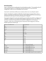
WinVue V4.1 User's Manual
Revision date Feb 20, 2013
This manual is for VueMetrix's WinVue, a user-interface program for all types of VueMetrix
controllers. For information specific to each controller refer to the individual product manual.
This manual describes WinVue 4.1, which contains features not found in previous versions.
Table of Contents
WinVue V4.1 User's Manual...........................................................................................................1
Introduction....................................................................................................................................3
General Procedures.........................................................................................................................4
Installation..................................................................................................................................4
Using the slide bars....................................................................................................................4
Using graph panes......................................................................................................................4
Connecting to one or more controllers......................................................................................5
Two types of USB...................................................................................................................5
Virtual serial ports.............................................................................................................5
Native USB (Human Interface Device).............................................................................6
Automatic connection on startup..........................................................................................6
Automatic connection after startup......................................................................................6
Forcing a connection after startup........................................................................................6
Connecting more than one controller...................................................................................6
Preventing the automatic scan of a specific RS-232 port.....................................................7
Modifying the baud rates used in WinVue's RS-232 port scan............................................7
Controller faults..........................................................................................................................7
Communication faults................................................................................................................8
Changing firmware.....................................................................................................................8
Sending low-level commands to the controller.........................................................................8
Squeezing the main window frame............................................................................................8
On startup..............................................................................................................................8
While the program is running...............................................................................................9
Changing which windows are open on start-up........................................................................9
Showing or hiding the pop-up help balloons............................................................................9
Long-term monitoring...............................................................................................................9
Getting firmware version number, unit serial number, and other low-level diagnostic
information.................................................................................................................................9
Send a list of pre-written commands (the Utilities->macro feature).....................................10
Laser Control..................................................................................................................................11
Turning the laser on..................................................................................................................11
Setting laser current..................................................................................................................11
Constant power mode (light regulation)..................................................................................11
Initial setup...........................................................................................................................12
For DPSS controllers........................................................................................................12
For MV, LV, HCT and HCV.............................................................................................12
The Main Laser Control Window.............................................................................................13
Laser temperature reading...................................................................................................13
System hour meter...............................................................................................................13
Laser voltage.........................................................................................................................13
Showing or hiding the laser power reading.........................................................................13
Setting current and power limits..............................................................................................14
Checking the laser temperature...............................................................................................14
Calibrating the laser power reading.........................................................................................14
Measuring an LIV curve...........................................................................................................15
Changing lasers.........................................................................................................................15
Using multiple laser controllers as a group (Laser->Multiple controller window)...............16
Changing the number of channels displayed......................................................................17
Pulsing the laser........................................................................................................................17
In pulsed mode, enable (turn on) the laser.........................................................................18
Simmer current....................................................................................................................18
Pulse control window...........................................................................................................18
Setting repetition rate......................................................................................................18
Setting pulse width..........................................................................................................19
Rise and fall times............................................................................................................19
Exact pulse width and repetition rate.............................................................................19
Measuring temperature................................................................................................................20
Changing the stored thermistor coefficients...........................................................................20
Active temperature control...........................................................................................................21
Operation without a computer connection (Autostart)..............................................................22
Using the TEC passthrough feature.............................................................................................23
Special TEC windows...............................................................................................................23
Revision History...........................................................................................................................24
Introduction
There is a different WinVue configuration for each VueMetrix product. This manual describes all
of the program's features, so if something is described here but isn't in your particular
configuration of WinVue it's not supported by your controller.
Note: the MC controller has a different user interface, which is not covered by this manual.
WinVue is distributed as a small executable file (.exe) and a large set of support files, some of
which are contained in sub-directories. The name of the small executable varies across products,
and indicates for which type of controller the program is configured.
The program is designed to connect only with the type of controller for which it is configured. All
VueMetrix controllers can, when asked, identify themselves by either RS-232 or USB. If WinVue
encounters a controller of a type that does not match its configuration, it will not make a
connection. Please refer to the following chart to determine which configuration of WinVue
matches a particular controller type.
WinVue executable name
Controller type
dpss
DPSS 0.8
dpss3
DPSS 3.0
dpss4
DPSS 4.0
hct
HCT
hcv
HCV-70
hcv2
HCV-100
hv
HV
lv15
LV-15
lv30
LV-30
mv
MV-12
MV-15
MV-21
MV-40
tec
TEC without passthrough
tec-hcv
TEC + passthrough to HCV-70
tec-hcv100
TEC + passthrough to HCV-100
tec-lv15
TEC + passthrough to LV-15
tec-lv30
TEC + passthrough to LV-30
tec-mv
TEC + passthrough to any MV-series controller
General Procedures
The procedures in this section apply to all WinVue configurations.
Installation
All configurations are installed the same way. The procedure is very simple.
•
If installing from a CD, drag the WinVue files to any convenient directory on the system,
preserving the subdirectory structure. Only a single drag operation is needed.
•
If installing from a zip file, simply unzip it to any convenient directory. The subdirectory
structure must be preserved, which should happen automatically with any standard unzip
utility. There are additional zip files within the distribution; the program expects them to
be in .zip format and they should not be changed.
•
Run the program by double-clicking on the icon of the executable.
Using the slide bars
WinVue has several floating-point slide bars. In many respects they are analogous to Windows
scroll bars. You can use them as follows:
•
Drag the “thumb” with the mouse.
•
Click or drag on the slider bar background. The value will jump in increments toward the
mouse cursor position.
•
Click or hold down the vernier buttons at the right or left edge of the bar. The value will
change in small increments.
•
Right click anywhere on the bar. A dialog will pop up where you can enter any desired
value. If you enter a value that's too large or too small, it will be automatically clipped.
•
To abort a drag, move the cursor away from the slide bar (just like a Windows scroll bar).
The slide bar will snap back to its previous position and nothing will be sent to the
controller.
During the process of dragging the slide bar, intermediate values are not sent to the controller.
The controller will change only when you release the mouse.
Using graph panes
Several windows contain graphs. In all cases the following controls are available:
•
Left click within the graph surface and then move the mouse wheel to zoom in or out. The
zooming action is centered on the cursor.
•
Right click within the graph surface and a utility window will appear. With this window
you can:
•
Save the graph as an image (.jpg)
•
Save the raw data as comma-separated text (.csv)
•
Copy the graph to the clipboard as an image (.jpg)
•
Copy the raw data to the clipboard as tab-delimited text
•
Print the graph
•
Zoom in an out using the slider
•
View the X and Y coordinates of the cursor position in the small grey fields.
Connecting to one or more controllers
WinVue connects to a controller by either RS-232 or USB. Some controllers can draw sufficient
power from the USB connection that a connection can be made when the controller isn't actually
turned on, but most types require the controller's input power to be turned on.
Two types of USB
There are two types of USB connections in the VueMetrix product line.
Virtual serial ports
Some of our controllers use a method called a virtual serial port, where the connection emulates an
RS-232 interface. Such a connection requires a third party driver, and when the cable is plugged
in the controller is assigned a standard port number such as “COM3.” After that it behaves in
most respects like a serial port. Controllers that support USB in this way are:
• All MV series
• HCT
• HCV-70
• HV
These products require the use of a third-party driver from Silicon Laboratories, called the CP210x
USB to UART Bridge VCP Driver (CP210x is the designation of the interface chip that implements
the USB protocol, and “VCP” stands for “Virtual COM port”). It is included on the standard
WinVue CD. It is also available from the web through the link above.
The driver installation utility is a single executable file, the function of which is to place the
proper driver on your system in a standard location. Run this utility before attempting to use the
controller's USB connection. When you first plug a USB cable into the controller's USB port,
Windows detects the connection and initializes the driver through the standard “New Hardware
Found” rigmarole. At that time a virtual COM port will be created and assigned an unused port
number; it will appear in the list of the Windows Device Manager as “COM” followed by a number.
After this initial installation, the computer will “recognize” the controller each time it is plugged
in and will silently create a virtual serial port with the same number. When the controller is
unplugged the virtual COM port will disappear.
In the rest of this section, the term “RS-232” includes this type of USB connection. The term
“USB” refers to a native USB interface supported by other types of controllers, explained in the
next section.
Native USB (Human Interface Device)
Other controllers support a native (and faster) USB interface, and appear to the operating system
as a “Human Interface Device” or HID. In the Windows Device Manager these will appear as USB
devices. Controllers that support USB in this way are:
• LV-15
• LV-30
• TEC
• HCV-100
These controllers require no installation – just plug in the cable and they are ready to go.
In the rest of this section, the term “USB” connection refers to this type (HID). The term “RS-232”
connection refers to emulated virtual serial ports as well as genuine RS-232 devices.
Automatic connection on startup
When WinVue is launched and a controller of the proper type is connected at that moment, the
connection will be made automatically. If multiple connections exist at start-up, they will be
enumerated in the “Communication” menu.
Automatic connection after startup
The the program can be started with no controller connected. When the first controller is
connected the interface will be made automatically.
An exception is when a second controller is connected by RS-232 after the program is running and
at least one controller is connected already. See the next section for what to do in this case.
Forcing a connection after startup
If WinVue is interfaced to at least one controller, and another one is later connected by RS-232,
WinVue will not detect the new one automatically (see a later section for why this is the case). In
this case, open the Communications->Communication info/setup window. Click on the button “Do
a serial port scan.” After a few seconds the new controller will appear in the Communication
menu list.
In the case of USB connections (for LV-15, LV-30, HCV-100, and TEC) this is not necessary; the
operating system identifies new controllers when they are plugged in. They are automatically
placed in the Communication menu list.
Connecting more than one controller
WinVue can handle multiple controllers. The controllers will all appear as a list under the menu
heading “Communications.” By selecting an entry from this list you can switch from one
controller to another. All the information in all of the windows will pertain to the controller
selected.
A special WinVue window has the ability to send commands to multiple laser controllers at once.
See the section titled “Using multiple laser controllers as a group.”
Preventing the automatic scan of a specific RS-232 port
At startup WinVue accomplishes the automatic enumeration of VueMetrix controllers by scanning
all the RS-232 ports on the computer. WinVue tries to send short messages that every VueMetrix
controller can understand, and when the proper reply is received the connection is made. This
process will continue until a controller of the proper type is found, so if WinVue is running with
no active connection all the serial ports on the computer will be periodically transmitting short
bursts of data. If you have other instruments connected it may be desirable to prevent WinVue
from sending data. You can exclude specific ports from WinVue's automatic scan by:
• Select Communications->Communication info/setup
• Click “Setup serial ports” and follow the instructions.
Port numbers entered into the list on the left are stored to a file on the hard disk and remain in
effect until you change them. Ports entered on the right are disabled temporarily, and will no
longer be excluded from WinVue's scan the next time it starts.
Modifying the baud rates used in WinVue's RS-232 port scan
By default WinVue tries three different baud rates (115200, 57600, and 19200) when it attempts to
connect to a VueMetrix controller. On computers with a large number of ports this becomes quite
time-consuming. If you know what baud rates your controllers will use, and you are not interested
in having WinVue detect controllers that use any other baud rates, you can reduce this time.
WinVue's baud rate list is controlled by the configuration file xxx_cfg.py (where “xxx” indicates
the name of the main program file), which is found in the “files” subdirectory below the main
program. Insert a line in this file resembling the following:
BAUD_RATES = [115200,]
Make sure the punctuation is exactly as shown, but you can change 115200 to 57600 (or to any
other standard baud rate). The example sets the list to have only one item, 115200 baud.
Note that this entry does not affect what baud rate a given controller will be able to understand; it
only affects how WinVue will scan for attached devices.
Note also that the line does not appear by default in the xxx_cfg.py, but if present it will override
the hard-coded default of [115200, 57600, 19200]. To return to the default behavior simply delete
the line or place a '#' at the beginning of it. The line can be inserted anywhere in the file.
Controller faults
All VueMetrix controllers detect certain operational faults. Some of these are routine conditions,
such as an open interlock or key switch; others are serious anomalies that would damage the
laser, the TEC or the controller itself if not acted upon. In all cases, the controller does what is
needed automatically, shutting off either the laser or the TEC current.
It is important to realize that these faults are not detected by WinVue but by the controller itself.
When a fault occurs, WinVue puts a red banner and a descriptive message in the upper right
corner of the main window. The controller remains in a fault condition (and the laser cannot be
started) until you act to “clear” the fault. The button next to the red banner becomes enabled in
this case, and you must click this button to clear the fault.
Communication faults
When WinVue is connected to the proper type of controller, a changing white icon appears in the
upper left corner of the main window. If the connection is lost the icon changes to a flat line. The
text to the right of the icon indicates the status of the connection. If errors occur they can be
listed from the Communications->Communication info/setup window (click “Fault log”).
Changing firmware
VueMetrix occasionally releases new versions of its controller firmware. These are distributed in
the form of small binary files, with extension of either .vmfs or .vmfp. These files are encrypted
and can only be read by WinVue.
The easiest way to perform an upgrade is to
• Place the file in the program's base directory (the one with the .exe file in it)
• From the WinVue menus choose Utilities->Change firmware.
• This window allows you to select the communication channel (in case there is more than
one controller on the PC) and the firmware file to be transferred. WinVue fills in these
fields automatically if possible. If more than one firmware file is found, it automatically
selects the one with most recent date. If you want to change either default value use the
buttons.
• Click Proceed. When the upload is finished the window will close automatically.
Sending low-level commands to the controller
WinVue communicates with controllers by means of simple strings of characters, sent by either
RS-232 or USB. Most of the controller's functionality is exposed somewhere in the WinVue
interface. In a few cases, however, it may be useful to be able to send specific commands directly.
To do this, select Utilities->Low level interface from the menu. Type a command into the top field,
hit enter, and see the controller's response in the second field.
The bottom part of the window provides a quick reference to the controller's full command set.
Squeezing the main window frame
WinVue 4.1 can shrink the main window frame until it is only large enough to enclose the open
windows. There are two cases:
On startup
This is controlled by the configuration file xxx_cfg.py (where “xxx” indicates the name of the main
program file), which is found in the “files” subdirectory below the main program. If this file
contains a line
SQUEEZE_ON_START = 1
the window frame will be shrunk. This line can be added anywhere with a text editor.
While the program is running
Select Window->Squeeze main window frame.
Changing which windows are open on start-up
This is controlled by the configuration file xxx_cfg.py (where “xxx” indicates the name of the main
program file), which is found in the “files” subdirectory below the main program. This file
contains a list of window names, such as:
WINDOWS['Service'] = 'closed'
WINDOWS['Communications log'] = 'closed'
The word on the right must be either 'open' or 'closed'. This can be changed with a text editor.
Showing or hiding the pop-up help balloons
The pop-up help balloons can be globally disabled or re-enabled by Help->Enable Balloon Help.
This choice is stored on the computer's hard disk and remains in effect until changed. In any
case, a given balloon will only appear five times unless it has changed (the laser on/off button's
help balloon is an example of one that changes as the function of the button changes).
Long-term monitoring
WinVue's Utilities->Data log window provides a simple way to log data from the controller. Once
you press the Start button, the program will periodically take some data and write it to a disk file.
With the user interface you can control how often this happens, what information is logged, and
the name of the log file. Any quantity that the controller can measure can be logged.
No data is ever erased. Each time a set of data is logged, once more record is appended to the file.
The file is in comma-separated-value (.csv) format, so it is readable by Excel or any other
spreadsheet program. Each data entry is time stamped.
If you close this window while logging is in progress, the logging will stop. You can also stop
logging by pressing the stop button.
Getting firmware version number, unit serial number, and other
low-level diagnostic information
The System Information window (under Utilities) provides system information, including:
•
System serial number. This also appears in the title bar of the main laser/TEC window.
•
Firmware version number
•
Calibration constants
This window was added in V4.1.0.12 – before that this information was in the Utilities-Service
window.
WinVue service window (Utilities->Service) provides a continuously updated display of the
controller's internal signals.
The internal signals vary from one type of controller to another. Since understanding this
information requires detailed knowledge of how the controller works, the display is mainly
intended for troubleshooting with assistance from the factory.
A button at the bottom of the window will capture the entire state of the controller at the instant
it is clicked, and log the result to a text file capture_log.txt. This file will be found in the program
folder.
Send a list of pre-written commands (the Utilities->macro feature)
You can send a sequence of commands to the controller in one step. Create a text file containing a
list of valid commands, including arguments, formatted just as if you were going to type them into
the “low-level interface” window. Each command must be on a separate line, and must not
include the special VueMetrix termination character '>'. For example, this will clear any faults, set
the current to 10A, and turn the laser on:
cf
i 10.0
l1
When you select Utilities->Macro, you get a Windows file dialog. Select the file with the list of
commands in it, and WinVue will send the whole sequence for you.
The macro feature does not report the controller's reply, but it will inform you if an error
occurred. Macros are not a useful way to query information from the controller.
Laser Control
Turning the laser on
VueMetrix laser controllers use a standard principle of laser safety: in order to make light, two
actions by the user are necessary. One is turning the laser on, and the other is setting a non-zero
current. There are several ways to turn the laser on, not all of which are available on every
product.
• Click the “Laser On” button (main laser window). This is a toggle button so a second click
will turn the laser off again.
• Use an external logic signal to turn the laser on and off. This feature is enabled or disabled
through the Laser->Laser options window.
• Use the Autostart feature.
Setting laser current
VueMetrix laser controllers use a standard principle of laser safety: in order to make light, two
actions by the user are necessary. One is turning the laser on, and the other is setting a non-zero
current. There are several ways to set the laser current.
• Use the slide bar on the Main Laser Control window.
• Use an external analog signal to set the current. This feature is enabled and disabled
through the Laser->Laser options window.
• Use the Autostart feature.
Constant power mode (light regulation)
Most VueMetrix controllers are capable of maintaining constant laser power. You set the power
level you desire, and the controller's task is then to adjust the laser current in order to achieve it.
The power detection capability, such as a monitor photodiode, and any associated circuitry is
supplied by you. The requirement is to send the controller a signal that's properly scaled and
proportional to the laser power. You also need to supply a calibration factor to convert this signal
to laser power in watts. The WinVue calibration window is convenient for this purpose.
When WinVue is configured for constant power operation, two radio buttons appear on the Main
Laser control window. These are used to switch back and forth between the two control modes.
The slide bar changes units as you do so, providing either a current scale or a light power scale. If
the check box “show power” (lower right corner of the window) is not checked, these radio
buttons will disappear. For constant power operation make sure this box is checked.
When you are running in constant power mode, the large numerical displays work as follows:
Mode
Power reading
Current reading
Constant power
Set point1
Actual
Constant current
Actual
1
“Set point” is what the controller is trying to achieve.
Set point1
Sometimes the controller may be unable to achieve the power value you asked for. This happens if
the laser is not capable of producing that much power, or if there is a problem with the detector
circuitry. The controller does not consider this to be a fault, so no red banner will appear in the
window. It will raise the current to the limit in an attempt to reach the set point. For this reason,
it is particularly important when using constant power mode to set the maximum laser current to
a value that will not damage your laser.
You can also set a maximum value for the light power, but this is primarily a convenience for
scaling the light power control slider. You cannot set a power value that exceeds the limit,
however, the current limit is always the important value for protecting the laser.
•
The controller always honors the current limit, whether the regulation mode is power or
current.
•
In constant current mode, the power limit has no effect.
Initial setup
The VueMetrix product line has two distinct types of constant power mode. DPSS controllers use a
different scheme than the others. The next two section describe the setup procedures for both
cases.
For DPSS controllers
DPSS controllers use hardware circuitry in a high-speed light regulation servo. These units
require only calibration of the power signal. Follow the calibration procedure, and after that the
use of the light loop is straightforward. All of the controls that you use on a daily basis are on the
main laser control window.
For MV, LV, HCT and HCV
On these controllers the power regulation is accomplished by firmware. Drift in the laser output is
effectively suppressed, and long-term stability is limited only by your power detector and its
circuitry. High speed noise suppression does not occur.
Setting up the firmware algorithm requires two steps. The first is to calibrate the power input
signal. The second step involves measuring the LIV curve of the laser and storing two coefficients
in the controller's memory: the laser threshold current and the laser slope efficiency. These two
numbers provide a simple linear approximation to the LIV curve.
When you turn the laser on, or change the light power, the controller's first step is to calculate the
new laser current based on these coefficients – in other words, based on the previously
determined approximation to the LIV curve. This quickly establishes a starting point that will be
reasonably close to the correct power. The coefficients play no further role, as the controller
periodically measures the laser power and makes adjustments to the current in order to maintain
the targeted power. This algorithm has the advantage of a rapid turn-on, and after a few
adjustments the remaining error is limited only be the accuracy and precision of the power
measurement. The correction rate on all types of controllers is at least once per millisecond.
Setup is easy with WinVue, and is explained in detail elsewhere in this manual. The two steps are:
•
Calibrate the laser power reading
•
Perform an LIV curve and transfer the coefficients to the controller
Note: Some standard versions of WinVue are not configured by default to allow constant power
operation. In this case, contact the factory at [email protected] for instructions.
The Main Laser Control Window
The “Laser on” button is a toggle. When it is depressed the laser is on; when it is released the laser
is off. WinVue will automatically release the button if the controller has shut off the laser for a
fault condition. It will also control the state of the button when Autostart is running or when the
use of an external on/off signal is enabled. In pulsed mode this button does not indicate whether
the laser is actually firing at this moment, but rather whether it is enabled - energized and capable
of producing light.
The large text fields below the button show laser power and current. The background is white if
the laser is on and gray if the laser is off.
If the laser is in constant power mode, the large power display is the set point – the value of power
you asked for. The current display shows the measured current, and has a slightly darker
background.
If the laser is in constant current mode, the large current display is the set point – the value of
current you asked for. The power display shows the measured power, and has a slightly darker
background.
The slide bar always shows the value you asked for, either current or power. If the laser is off, it
represents the value of current or power that will be produced when the laser is turned on. If the
laser is on, the slide bar value always matches one of the large display values (either current or
power).
If you turn the laser on and WinVue quickly tells you that it is off again, you have a fault condition.
The red banner in the upper right corner of the main window describes the fault.
Laser temperature reading
The main laser control window provides a display of the laser temperature. The controller gets
this information by digitizing the voltage on an input pin and converting that voltage to a
temperature. This number is meaningful only if an appropriate thermistor is located near the
laser, and if necessary the calibration procedure has been done. If this isn't the case, ignore this
readout. For further information see about thermistors, see our web site.
System hour meter
This number indicates the controller's total hours of operation. It increments only when current
is flowing either to a TEC or the laser.
Laser voltage
This is the measured voltage across the controller's laser output pins. The actual voltage at the
laser itself may be less due to losses in the wires.
Showing or hiding the laser power reading
A check box on the lower left of the main laser control window hides and shows the laser power
reading. This choice is stored on the computer's hard disk and remains in effect until changed.
This is useful if you don't apply a meaningful signal to the controller's power sense input pin, in
which case the power display is not valid.
Setting current and power limits
Use Laser->Set Limits. Type in the new values and click the button. The slide bar on the Main
Laser Control window will rescale to show the new limit. By using this feature to restrict the
output laser current, you can prevent an inadvertent mouse click from producing an over-current
condition.
The power limit is only for convenience in using constant power mode. It allows you to limit the
power setting to a range that matches the physical capabilities of your laser. This does not restrict
the controller's performance; specifically it does not prevent you from switching to current
regulation mode and exceeding this power level.
The current limit, on the other hand, will be strictly honored by the laser driver and will never be
exceeded. This is the recommended way to prevent damage to the laser.
Checking the laser temperature
The controller can check the laser temperature and prevent you from running the laser unless its
temperature is in the correct range. You have to set up the temperature sensor properly for this
to work.
This feature can be turned on and off in the Laser->Laser options window. After changing one of
the temperatures you have to transmit the new value to the controller by clicking the button. The
checking is done by the controller, not by WinVue.
Calibrating the laser power reading
This is an essential step in setting up constant power operation, and to obtain a meaningful
display of laser power.
VueMetrix controllers have an input pin that accepts an analog signal from a monitor photodiode
(MPD) or similar device for measuring laser power. This section will refer to this signal as the
“MPD,” since many laser diodes are packaged with an embedded photodiode that is convenient for
this purpose. Any method of measuring power can be used so long as it results in a signal that the
controller can accept. See the individual product manuals for details.
The controller can digitize this signal, apply a calibration factor, and produce a reading of laser
power in watts. You must provide this signal if you want to operate in constant power mode
(where that feature is available), but in other cases it is optional.
WinVue displays the power reading in large numbers on the left of the main laser control window.
This display can be hidden if you aren't providing the signal - uncheck the box on the lower right
of the window.
In order for the power number to be correct, the controller must know the correct calibration
factor to convert the measured input signal to watts. Since that depends on your equipment, the
factory setting is purely a placeholder and is not useful.
To perform this calibration you will use the window Laser->Calibrate power measurement. Turn
the laser on in current control mode and set a typical operating current. You must have a way of
determining the actual laser power under these conditions.
The window provides a continuous reading of the voltage on the MPD input pin, and shows you the
calculated value of power based on this voltage. To set a new calibration constant, you can either:
• Enter the known value of the power in watts.
• Enter the calibration factor directly. The displayed power will be the product of this
number and the voltage on the MPD pin.
The result will be transmitted to the controller and stored in non-volatile memory. The controller
can now report the power in watts at any time; once the calibration is set correctly, WinVue does
not compute the power but periodically asks the controller for it.
Measuring an LIV curve
This is an essential step in setting up constant power operation on HCT, HCV, LV or MV.
WinVue can measure the laser's LIV curve (light-current-voltage; also called PIV, power-currentvoltage), a standard laser performance characteristic. This is a useful diagnostic. Before
measuring an LIV curve, the laser power reading must be calibrated.
Open the window Laser->LIV. Fill in the four boxes on the upper left as follows:
• Beginning laser current – WinVue will map out the curve between this value of current and
the ending laser current.
• Ending laser current – This defaults to the maximum current, set elsewhere.
• Number of points
• Delay between points – By default, WinVue sets a new current value and makes
measurement as fast as its communication channel will allow. The typical delay is a few
milliseconds. If your power measurement has a long time constant this will result in
systematic errors. In this case, enter a non-zero number here to make WinVue wait
between setting the current and reading the power.
The buttons let you start and abort the measurement. When the curve is finished, WinVue
analyzes the data and fills in the boxes at the lower left with the threshold current (in amps) and
the slope efficiency (in watts/amp).
If you are measuring an LIV curve as part of the constant power setup procedure, you must now
hit the button “Upload constants to controller.”
Changing lasers
When you change the laser on a VueMetrix controller, normally no action is required to get the
new one to work. There are several steps that you should consider, however, that will help to
protect the laser against damage. The following checklist may be useful:
•
Be sure the maximum current is set correctly.
•
If you are using the power readout, check the calibration.
•
If you are using constant power mode, check the setup.
•
If you are using the laser over/under temperature settings, check those values and also the
temperature readings.
Using multiple laser controllers as a group (Laser->Multiple
controller window)
Using this window you can act on multiple controllers as a group. This window is different from
others because it relates to all the controllers that are currently attached to the PC. Other
windows reflect the state of just one controller, specifically, the one that is currently selected in
the Communication menu list. You can change this selection at any time without affecting what
the Multiple Controller window is doing.
The spreadsheet-like chart is the key to using this window. All of the attached controllers appear
here, indexed by their serial numbers. Some of the cells in this table are clickable and others only
provide information. The second column controls whether or not a particular controller is “in the
group.” The “group” is important because the buttons and sliders at the top of the window change
the controllers in the group; those that aren't in the group do not change.
Initially all the controllers are in the group. To include or exclude one of them, click directly on
the corresponding check box in the “in group” column.
The rest of the columns work as follows:
•
•
•
•
•
•
•
•
•
on (clickable) – This corresponds to the “Laser on” button: a check mark means the laser is
enabled. A click in this cell changes the state of this controller.
fault (information only) – If the controller has a fault this cell will so indicate. If the
controller is in the group, you can clear the fault by clicking the button in the upper right
of this window. If the controller is not in the group, you need to select it from the
Communication menu list and clear the fault by clicking on the upper right “Clear fault”
button in the main WinVue frame.
regulation (clickable) – if the controllers have constant power regulation capability, this
cell shows the regulation mode. A click here changes to other one.
current (editable) – this cell contains the current set point. Editing the number sends a new
current command to the controller.
power (editable) - this cell contains the power set point. Editing the number sends a new
power command to the controller.
hours (information only) – the system operating hours
voltage (information only) – the voltage across the laser drive terminals
temperature (information only) – the measured laser temperature
mode (information only) – tells you how the laser is being controlled; possible values are:
• Standard – controlled by the current/power setting
• ext or ext current – current set by an external analog voltage
• ext on/off – laser is enable/disable by an external logic signal
The buttons and sliders at the top of the window act on all the controllers in the group.
Commands are sent as rapidly as the communications capability of the PC will allow. The controls
act as follows:
•
All on – turns them all on.
•
All off – turns them all off.
•
Set all currents – sets them all to the same current, regardless of what it was before. If one
or more of them was in constant power mode, this will switch them back to constant
current mode.
•
Set all powers - sets them all to the same power, regardless of what it was before. If one or
more of them was in constant current mode, this will switch them back to constant power
mode.
•
All constant current – sets them all to constant current regulation.
•
All constant power – sets them all to constant power regulation.
•
Clear faults – clears the faults on all of them.
Changing the number of channels displayed
By default WinVue can display 20 channels. This number is controlled by the configuration file
xxx_cfg.py (where “xxx” indicates the name of the main program file), which is found in the
“files” subdirectory below the main program. Insert a line in this file of the following form:
MULTIPLE_MAX = 20
The number “20” should be replaced by whatever number of channels you want the program to
display. By default this line does not appear in the xxx_cfg.py file, but if it is present it will
override the hard-coded default of 20. To return to the default behavior simply delete the line or
place a '#' at the beginning of it (the '#' symbol indicates a comment and so the rest of the line is
ignored). The line can be inserted anywhere in the file.
Feature added in V4.1.0.13
Pulsing the laser
VueMetrix laser diode controllers, with the exception of the DPSS series, are capable of
periodically pulsing the laser current on and off. This is called “pulsed mode.” There are two
ways of clocking the on/off cycles:
•
Internal – the controller itself decides when to turn the laser on and when to turn it off.
You set two parameters that define how frequently and for how long the laser current is
on: the repetition rate and the pulse width. When internal pulsed mode is on, the controller
produces a continuous stream of pulses having the desired properties.
•
External – an external logic signal, applied to one of the controller's pins, turns the laser on
and off. The settings for pulse width and repetition rate are ignored, and the laser current
will follow the logic level of the input pin.
In this mode there will be a maximum repetition rate that cannot be exceeded. When
pulses arrive too close together at the input pin, some of them will be ignored in order to
keep the repetition rate at or below the limit. The maximum repetition rate varies from
one product to another - consult the manual.
The pulsed mode settings consist of four parameters:
•
Pulsed mode on or off. If pulsed mode is off, the laser current will be continuous (cw). None
of the other parameters are meaningful. If pulsed mode is on, the laser current will be
controlled in accordance with the other three parameters.
•
Internal or external. In internal mode the pulse repetition rate and pulse width are in
effect. In external mode these parameters are not meaningful.
•
Repetition rate. In internal pulsed mode this number is used to determine how often to
turn the laser current on.
•
Pulse width. In internal pulsed mode this number is used to determine how long the laser
current stays on.
All four of these parameters are stored in the controller's non-volatile memory, so once they are
set they remain in effect even when the controller is turned off and back on.
The maximum repetition rate and the minimum width of the pulse vary from one product to
another. WinVue is configured correctly and will not allow any of the parameters to be set to an
invalid value.
WinVue does not play any role in generating pulses, it is simply displaying how the controller is
set up. The actual production of the pulses occurs without any intervention from WinVue.
In pulsed mode, enable (turn on) the laser
The pulsed mode settings are independent of the laser on/off button and the laser current setting.
In order for the laser to produce light, you must turn the laser on (click the Laser on button) and
set a non-zero current with the slide bar. In pulsed mode, the Laser On button can be thought of
as “enabling” the laser – energizing the drive circuitry and making it capable of producing
current. Whether the laser is actually on at any given instant is dependent on the pulsing logic.
Simmer current
In pulsed mode, with the laser on button clicked and a non-zero current selected, the laser is never
actually off. Between pulses, all VueMetrix controllers maintain a small “simmer” current
through the laser. Some voltage will be observed across the laser even when the pulsing logic is
off.
On most products this simmer current is set at the factory, and is always designed to be far below
the typical lasing threshold. On HCV-100 it is possible to program this current using the Laser>Laser options window. Increasing it to just below the lasing threshold may reduce the rise time of
the laser pulse, at the expense of slight additional heating.
Pulse control window
Setting repetition rate
The repetition rate is set by a standard WinVue slide bar. Since repetition rates may extend over
several orders of magnitude, a text window is also provided where you can type in a value in Hz
(hit Enter when finished). The controllers are capable of handling repetition rates much less than
1 Hz.
As you move the repetition rate slide bar or type a number into the text box, the pulse width slide
bar will change scale and the thumb will move. This provides a quick visual indication of the duty
cycle (the fraction of time when the laser is on).
Setting pulse width
The pulse width is set by a standard WinVue slide bar. For precise settings, a text window is also
provided where you can type in a value in seconds (hit Enter when finished).
The pulse width slide bar is scaled so that the thumb position always represents the duty cycle (the
fraction of time when the laser is on). If the thumb is on the left edge the duty cycle is close to 0%,
on the right edge it is close to 100%. All controllers support the extremes (always on and always
off).
Rise and fall times
Electrical circuits do not rise and fall instantly, but require some finite amount of time to reach
their nominal level. Each controller has a characteristic rise time; the fall time is typically a
characteristic of the laser diode. Therefore in pulsed mode the laser current is not a perfect
square wave, and at the highest repetition rates or narrowest pulse widths this may be easily
noticeable.
Consult the individual product manuals for typical rise times of each controller type.
Exact pulse width and repetition rate
Internal timings are obtained with a internal digital timer. When you select a repetition rate and
pulse width, the controller tries to produce the requested values as closely as possible. Some
quantization error will occur if the repetition rate or pulse width does not match one of the
available digital values. On the WinVue interface, the exact timing information is presented in the
table at the bottom of the pulse control window. The first line indicates the system's repetition
rate limit. Subsequent lines give the exact pulse width, repetition rate, and duty cycle for the
parameters you have selected.
Measuring temperature
VueMetrix controllers determine temperature by measuring the resistance of a thermistor. See
the document “Temperature control and measurement” for details. A set of adjustable coefficients
is used to convert resistance to temperature. We have designated one particular thermistor as our
default, and every controller ships from the factory with appropriate coefficients for that. The
coefficients can be changed to accommodate different thermistor types, or to account for
individual differences between thermistors.
To calculate a new set of coefficients, use the Thermal->Calculate thermistor coefficients window.
This window is self-explanatory, but you should be aware that the calculation depends on two
controller characteristics: a reference voltage and a fixed resistor (part of the circuit that senses
the thermistor's resistance). These values are different from one type of controller to another.
WinVue is aware of the correct values for each type, but if you own more than one kind of
controller you must be careful to use the correct version of WinVue. For more details see the web
site.
Changing the stored thermistor coefficients
If you know the coefficients and they are different from the defaults, you can enter them directly
without calculating them again:
• On TEC controllers you use the Thermal=>TEC setup window, “Thermistor” tab.
• On other controllers use Thermal->Enter thermistor coefficients.
Active temperature control
Our web site contains an important resource for this topic.
Some VueMetrix controllers can actively control the temperature by driving a thermoelectric
cooler (TEC), also known as a Peltier effect cooler. Controllers with this feature include:
•
TEC
•
HCT
•
DPSS series
To use active temperature control, you must supply a thermistor of the proper type and place it
near the object whose temperature you want to stabilize. Further information about thermistors
and how to use them with VueMetrix controllers can be found on our web site. If you use our
standard thermistor, calibration coefficients are already stored in the controller. If you use a
different type, or need better absolute temperature accuracy, calibration will usually be necessary.
Refer to the section “Measuring temperature,” and to the information on our web site.
Our controllers regulate the thermistor's temperature using a firmware-based servo algorithm,
the theory of which can be found on our web site. The algorithm depends on two coefficients that
have to be “tuned” for your system. The factory settings may work but will probably not be
optimized. Use the Thermal->Temperature servo tuning window to run this procedure. You won't
have to do this on a daily basis: do it once for a new system, and repeat it any time something
changes.
On a daily basis you need only to turn the servo on and off and to set the target temperature (the
set point). WinVue's TEC control window lets you do this, and also shows you a display of the
measured temperature and the amount of TEC drive being used. Any fault conditions are also
reported. On DPSS or HCT controllers, a fault in the temperature servo will shut off the laser
automatically; a fault in the laser driver will not shut off the temperature control.
The window varies slightly from one product to another. Some controllers have the capability of
monitoring the TEC current and some do not. Some have dual TECs and others have only one. In
each case the basic controls are the same: an on/off button, and a slide bar to set the desired
temperature. The range of the slide bar and the sensitivity of the error display are set by the
“Configure” button. On TEC controllers, a display values at the bottom of the window gives system
hours.
Operation without a computer connection (Autostart)
All VueMetrix controllers (with the exception of MC) can be run without a host computer, a
feature we call Autostart. All of the controller's functions are fully supported, including constant
power operation, external analog control and pulsing (where available). The basic idea is that the
controller can be set up to stabilize the temperature if it has a TEC controller, turn the laser on,
and set the laser current (or power) to a predetermined value without intervention of any kind. In
some cases, a VueMetrix controller can function as the “brains” of an entire laser system,
eliminating the need for any external interface whatsoever.
For laser controllers, WinVue's Autostart window (Utilities->Autostart) can be used to set up and
test the Autostart feature. Once the set up is complete the controller will run without WinVue,
simply by turning it on.
TEC controllers have a simple check box on the Main TEC control window. Autostart is quite
simple on these units: if the check is checked, the servo is turned on automatically when the the
controller is started.
USB users please note: Some controllers can draw sufficient power from a USB connection to keep
the unit alive. To turn these units completely off you must disconnect the cable as well as turn the
power off.
Autostart is fully documented on our web site.
Using the TEC passthrough feature
TEC controllers have an extra RS-232 port and the capability of connecting to a second controller
by passing messages through. This allows the two controllers to function as a unit. Further details
are given in the TEC manual and on our web site.
A WinVue for TEC installation contains several executables that support passthrough – see the
chart. Each of the executables presents the TEC windows. The passthrough executables also
present windows for the second (laser) controller. In the pull-down menus on these
configurations of WinVue, the menu text indicates which windows are passthrough (laser-related)
and which are for the TEC.
Take care not to run a passthrough configuration of WinVue unless you really have a second
controller of the correct type connected. Do not try to run the program when the TEC controller is
powered up and the second controller is not. WinVue will attempt to send messages to the second
controller and will wait for a reply, resulting in communication errors and bottlenecks.
WinVue handles faults seamlessly in the passthrough configuration. When a fault occurs in the
second controller it will appear in the usual place (the upper right of the WinVue screen).
Pressing the “Clear Fault” button will clear the faults in both controllers.
At the present time, the macro and upgrade firmware features of WinVue are not available for the
second controller in a passthrough configuration.
Program name
Second controller type
tec.exe
- none -
tec_hcv100.exe
HCV-100
tec_lv15.exe
LV-15
tec_lv30.exe
LV-30
tec_mv.exe
MV
Special TEC windows
TEC controllers have a unique window, TEC monitor. They have another window, TEC setup, that
is different from other controller types that have TEC drivers in them. Those windows are
documented in the TEC manual.
Revision History
Initial Release October 16, 2012
Revision February 20, 2013
•
Added section on changing baud rate list
•
Added section on changing the number of lines in the multiple controller window
(V4.1.0.13 and later)
•
Revised the “Getting firmware version . . .” section to reflect the new System Information
window.