1
CW12832 User Manual
by
CW12832
Display
CW12832 User Manual
by Cwlinux Limited
Published April, 2007
Copyright 2007 Cwlinux Limited, All rights reserved.
Cwlinux Limited makes no representations or warranties with respect to CW12832 or to the
contents or use of this manual, and specifically disclaims any express or implied warranties of
merchantability of fitness for any particular purpose.
Permission is granted to copy and distribute modified versions of this documentation under
the conditions for verbatim copying, provided also that the entire resulting derived work is
distributed under the terms of a permission notice identical to this one.
Permission is granted to copy and distribute translations of this documentation into another
language, under the above conditions for modified versions.
Linux is a registered trademark of Linus Torvalds.
All trademarks, registered trademarks, and service marks are the property of their respective
owners.
CW12832
Display
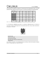
Revision History
Author
Revision
Content
Date
IL
1
Initially released
30-7-2002
IL
2
New features added
24-2-2003
IL
3
Drawings added
6-3-2003
IL
4
New features added
23-5-2003
GT
5
New features added
20-04-2007
CW12832
Display
Table of Contents
Chapter 1.Introduction............................................................................................................7
1.1.Introduction..................................................................................................................7
1.2.Features.......................................................................................................................7
1.3.Installation and Connection..........................................................................................7
1.3.1.Serial Connection.................................................................................................7
1.3.2.Power Connection................................................................................................8
1.3.3.USB Connection...................................................................................................9
1.3.4.USB Driver.........................................................................................................10
1.3.5.USB Driver for Windows.....................................................................................10
1.3.6.GPIO, Relay Pin Assignments............................................................................10
1.3.7.Installation...........................................................................................................11
1.3.8.Test the Module..................................................................................................12
1.3.9.Demo Software(Boot up logo example).............................................................13
1.3.10.Serial Number Notation....................................................................................16
Chapter 2.Module Programming..........................................................................................17
2.1.Command Sending....................................................................................................17
2.2.Flowchart....................................................................................................................17
Chapter 3.Text Mode...........................................................................................................18
3.1.Built in Characters.....................................................................................................18
3.2.Writing Text to CW12832...........................................................................................19
3.3.Text Commands.........................................................................................................19
3.3.1.Auto Line Wrap ON (254 67 253).......................................................................19
3.3.2.Auto Line Wrap OFF (254 68 253).....................................................................19
3.3.3.Auto Scroll ON (254 81 253)..............................................................................19
3.3.4.Auto Scroll OFF (254 82 253).............................................................................19
3.3.5.Text Insertion Point (254 71 [column] [row] 253)................................................19
3.3.6.Set Text Insertion Point to Top Left (254 72 253)..............................................19
3.3.7.Turn On Underline Cursor (254 74 [column] [row] 253).....................................20
3.3.8.Turn Off Underline Cursor (254 75 253).............................................................20
3.3.9.Move Cursor Left (254 76 253)...........................................................................20
3.3.10.Move Cursor Right (254 77 253)......................................................................20
CW12832
Display
3.3.11.Turn On Text Inverse (254 102 253)..................................................20
3.3.12.Turn Off Text Inverse (254 103 253)...................................................20
Chapter 4.Bar Charts, User Defined Characters and Graphics.............................21
4.1.Introduction..................................................................................................21
4.2.Command List..............................................................................................21
4.2.1.Initialize Wide Vertical Bar Graph (254 118 253).................................21
4.2.2.Initialize Narrow Vertical Bar Graph (254 115 253)..............................21
4.2.3.Draw Vertical Bar Graph (254 61 [column] [height] 253).....................21
4.2.4.Erase Vertical Bar Graph (254 45 [column] [height] 253)....................21
4.2.5.Draw Horizontal Bar Graph (254 124 [column] [row] [length] 253)......21
4.2.6.Erase Horizontal Bar Graph (254 43 [column] [row] [length] 253).......21
4.2.7.Define Custom character (254 78 [cc] [6 bytes] 253)...........................21
4.2.8.Put Pixel (254 112 [x] [y] 253)...............................................................23
4.2.9.Clear Pixel (254 113 [x] [y] 253)...........................................................23
4.2.10.Draw Byte (254 62 [x] [row] [byte] [4 dummy bytes] 253)..................24
Chapter 5.Miscellaneous Commands....................................................................25
5.1.General Command List................................................................................25
5.1.1.Read Model Number (254 48 253).......................................................25
5.1.2.Read Firmware Version (254 49 253)..................................................25
5.1.3.Soft Reset (254 86 253).......................................................................25
5.1.4.Clear Display (254 88 253)...................................................................25
5.1.5.Set Display Contrast (254 104 [contrast] 253).....................................25
5.1.6.Set RS232 port speed (254 57 [speed] 253)........................................25
5.1.7.Save screen as boot-up logo(254 106 253).........................................25
5.1.8.Display boot-up logo(254 105 253)......................................................26
5.1.9.Restore factory default boot-up logo(254 107 253).............................26
5.2.Backlight Command List..............................................................................26
5.2.1.Backlight On (254 66 253)....................................................................26
5.2.2.Backlight Off (254 70 253)....................................................................26
5.2.3.Backlight Brightness (254 65 [brightness] 253)....................................26
5.3.Keypad Command List.................................................................................26
CW12832 User Manual
5
CW12832
Display
5.3.1.Auto Key Hold On (254 50 253)...........................................................26
5.3.2.Auto Key Hold Off (254 51 253)............................................................26
5.3.3.Keypad Mapping...................................................................................27
5.4.Non-Volatile Memory Command List...........................................................27
5.4.1.Save User Defined Character in Non-Volatile Memory (254 79 [cc]
253)................................................................................................................27
5.4.2.Load User Defined Character in System RAM (254 80 [cc] 253).........27
5.4.3.Save User Settings in Non-Volatile Memory (254 83 [ud] [4 bytes] [2
dummy bytes] 253)........................................................................................27
5.4.4.Read User Settings from Non-Volatile Memory (254 84 [ud] 253)......28
5.5.GPIO Command List....................................................................................28
5.5.1.Turn ON General Purpose Output (GPO) (254 99 [gpo#] 253)...........28
5.5.2.Turn OFF General Purpose Output (GPO) (254 100 [gpo#] 253)........29
5.5.3.Read Status of General Purpose Input (GPI) (254 101 [gpi#] 253).....29
Chapter 6.Command Summary..............................................................................31
6.1.Text Command Summary............................................................................31
6.2.Bar Charts and Graphic Command Summary.............................................32
6.3.Miscellaneous Command Summary............................................................33
6.4.Text Mode Coordinates...............................................................................36
Chapter 7.LCD Specifications................................................................................37
7.1.Features.......................................................................................................37
7.2.Mechanical Specifications............................................................................37
7.3.Absolute Maximum Ratings.........................................................................37
Chapter 8.Appendix................................................................................................39
CW12832 User Manual
6
CW12832
Display
Chapter 1. Introduction
1.1.
Introduction
The CW12832 is a graphical LCD which user can show both text and graphics at the same time
via a connection of a computer/appliance/server. The module includes a set of simple commands
that allows user to develop his own LCD environment easily.
1.2.
Features
21 columns × 4 lines text display
128 × 32 dots graphic display
Text wrap, scroll and inverse capability
Built in characters plus 16 user defined characters
Communicate over RS232 or USB interface
Baud rate speed selection between 9600 and 19200 bps
Programmable on/off and brightness of the LED backlight
Horizontal and vertical bar charts
32 bytes reserved non-volatile memory spaces for user settings
6 buttons keypad
4 general purpose I/Os
1 reed relay used as a host on/off switch
Fit in a standard 3.5" floppy drive bay
1.3.
1.3.1.
Installation and Connection
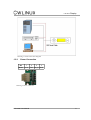
Serial Connection
Only simple connection is required. CW12832 obtains power from the PC standard floppy power
connector (Drawing 2). User should take extremely care in connecting the power to CW12832.
Reversing the polarity of connector will result in burning the CW12832.
Drawing 1 shows how to connect a CW12832 to a Personal Computer, a 1U appliance or a Server
Station. For serial CW12832, user requires to connect a DB9 cable (Standard COM port cable) together with a power cable (Standard Floppy Drive Power Cable) only.
CW12832 User Manual
7
CW12832
Display
Drawing 1 Serial connection diagram.
1.3.2.
Power Connection
Pin
1
2
Name
VCC
TXD
3
4
RX_D GND
Drawing 2 Power connector.
CW12832 User Manual
8
CW12832
Display
User should take extremely care if he intended to connect it with another type of power supply.
Please notice the pin assignments of the power connector before plugging the power into
the CW12832. Improper connection of the power will burn the CW12832.
The bouncing reset switch SW1 is used to reset the micro-controller whenever necessary. Remote
reset switch can also be found in JP1, please refer to the GPIO description in session 1.3.7.
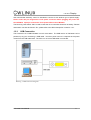
1.3.3.
USB Connection
The Connection of a USB CW12832 is much more easier. The USB version of CW12832 can be
powered up by just connecting a USB cable. No other power source is required as the power
comes from the USB cable itself. The LCD is on once the USB cable is connected.
Drawing 3 USB connection diagram.
CW12832 User Manual
9
CW12832
1.3.4.
Linux
Display
USB Driver
driver
for
the
USB
version
of
CW12832
can
be
obtained
at
http://www.cwlinux.com/eng/downloads. Type in the followings (only in Linux) to load the driver,
# tar zxf ld_pl2303_v0213.tar.gz
# cd ld_pl2303_v0212
# make
# modprobe usb-ohci or modprobe usb-uhci
# insmod usbserial.o
# insmod pl2303.o
Note: Although the stock version of Linux driver works, it has problem during high speed transfer.
This driver fixes the problem. It is recommended to use the above driver instead of the stock driver.
1.3.5.
USB Driver for Windows
Latest version of USB driver for CW12832 can be downloaded at http://tech.prolific.com.tw. In the
website, search for latest driver for PL-2303. Then, install the driver according to the readme file.
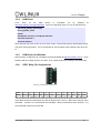
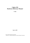
1.3.6.
GPIO, Relay Pin Assignments
Drawing 4 GPIO pin assignments.
Pin
1
2
3
4
5
6
7
8
9
10
11
12
Name GPO0 VCC GPO1 RST GPO2 GPI0 GPO3 GPI1 NC INT0 NC GND
User can control or read status of other external I/O devices through the GPIO. Detail description
of the GPIO and the on board relay can refer to sessions 5.5.1 to 5.5.5. RST is the reset pin of the
CW12832. Connect it to +5V will reset the CW12832. INT0 is reserved for future purpose. It is
recommended to leave it unconnected.
CW12832 User Manual
10
CW12832
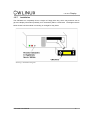
1.3.7.
Display
Installation
The CW12832 can completely fit into a single 3.5" floppy drive bay, which may enhance user to
get more display information (basically 21x4 characters) within a small area. The diagram drawn
below shows how the module is mounting on a single PC bay insert.
Drawing 5 Installation diagram.
CW12832 User Manual
11
CW12832
1.3.8.
Display
Test the Module
User can test the module in the following way (in Linux),
1. Open the minicom
2. Press [Ctrl A] then [O] to bring up configuration
3. Choose “Serial port setup” in configuration
4. Change item A to /dev/ttyS0 if user is using the serial CW12832 and is connected to
COM1
5. Change item A to /dev/ttyS1 if user is using the serial CW12832 and is connected to
COM2
6. Change item A to /dev/ttyUSB0 if user is using the USB CW12832 and is connected to
USB port
7. Change item E to 19200 8N1 as this is the default value of CW12832 during power up.
8. Exit “Serial port setup”
9. Choose “Save setup as dfl1” in configuration
10. Exit configuration
11. Re-open minicom
12. Type some characters on keyboard and it should appear on the LCD.
CW12832 User Manual
12
CW12832
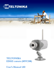
1.3.9.
Display
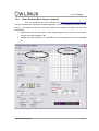
Demo Software(Boot up logo example)
User can download the demo software from http://www.cwlinux.com/downloads .
The Demo Software for CW12832 is a Win32 application, which is compatible to Windows 95, 98,
and XP. Just double click and run the program. Below is an example to change the boot up logo
of CW12832.
1. Double click and run the program. After setting program to the correct port and speed,
change to the "Demonstration" tab.
2. Change the "Demo selection" to "Load BMP", this would enable the section to load BMP
file.
Drawing 6 Boot up logo example
CW12832 User Manual
13
CW12832
Display
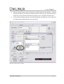
3. Click the "Browse" button and it will pop-up a window listing the file directory.
Browse
through the directory and select the bmp image for the boot up logo. Note that the bmp
image has to be in pixel size 128 width x 32 height in mono color(black and white only).
4. If you choose the image correctly, the image information will be shown on the right, and
an image preview should be shown in the box above.
Drawing 7 Boot up logo example
CW12832 User Manual
14
CW12832
Display
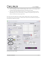
5. Click "Load Image" button to load the image to the CW12832. After clicking the button,
you should see CW12832 displaying the image you selected in previous steps.
6.
Click "Save" button under the "Boot up Logo" section. It would issue the command to save the
image displaying on screen as the boot up logo. A message box saying "Boot up logo saved" will
come up to indicate the new boot up logo is saved.
Note: Next to the "Save" button, there are "Show" and the "Default" buttons. "Show" button refresh the
screen and show the current boot up image. "Default" button will erase the user defined boot up image, and
restore the factory default boot up image.
Drawing 8 Boot up logo example
CW12832 User Manual
15
CW12832
1.3.10.
Display
Serial Number Notation
We provide different versions of CW12832 for user to choose. User can choose the one which suit
to his application. Here listed below is the explanation of a serial number.
CW 12832 Y-G KS
Item
Meaning
CW
CWlinux
12832
LCD dots resolution
Y
Backlight color
G
Graphic supported
K
Keypad supported
S
S - Serial, U - USB
CW12832 User Manual
16
CW12832
Display
Chapter 2. Module Programming
2.1.
Command Sending
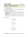
Commands are sent via the RS232 port together with 2 other numbers, the command starts with
[254] and ends at [253]. For example, in PC, user will need to write the following lines in order to
send a complete command to LCD12232.
Void LCD_Write_Command(BYTE [command])
{…………
LCD_Write(254);
LCD_Write([command]);
LCD_Write(253);
………..
};
2.2.
Flowchart
Drawing 9 Flowchart.
CW12832 User Manual
17
CW12832
Display
Chapter 3. Text Mode
3.1.
Built in Characters
Size of all built in characters is defined by a 6 x 8 dot matrix. User is required to send the ASCII
code of the corresponding character in order to display it. Details of the ASCII information of each
character are listed as the following table. A font table is available in the appendix of this manual.
Note: UD stands for User Defined.
ASCII
Character
ASCII
Character
ASCII
Character
ASCII
Character
1
UD
44
,
72
H
100
d
2
UD
45
-
73
I
101
e
3
UD
46
.
74
J
102
f
4
UD
47
/
75
K
103
g
5
UD
48
0
76
L
104
h
6
UD
49
1
77
M
105
i
7
UD
50
2
78
N
106
j
8
UD
51
3
79
O
107
k
9
UD
52
4
80
P
108
l
10
UD
53
5
81
Q
109
m
11
UD
54
6
82
R
110
n
12
UD
55
7
83
S
111
o
13
UD
56
8
84
T
112
p
14
UD
57
9
85
U
113
q
15
UD
58
:
86
V
114
r
16
UD
59
;
87
W
115
s
32
[space]
60
<
88
X
116
t
33
!
61
=
89
Y
117
u
34
“
62
>
90
Z
118
v
35
#
63
?
91
[
119
w
36
$
64
@
92
\
120
x
37
%
65
A
93
]
121
y
38
&
66
B
94
^
122
z
39
‘
67
C
95
_
123
{
40
(
68
D
96
`
124
|
41
)
69
E
97
a
125
}
42
*
70
F
98
b
126
~
43
+
71
G
99
c
Table 1 Characters table
Apart from the built in characters listed in the above table, user can define his own characters in
spaces from [0x01] to [0x10]. Details of how to define a character may refer to section 4.2.7.
CW12832 User Manual
18
CW12832
3.2.
Display
Writing Text to CW12832
When user sends a character to CW12832, it displays at location which specified before. The next
character will automatically display at the location next to the previous character. Characters
which are drawn please refer to the built in characters table showed above. User is required to define his own character sets before he can show it.
3.3.
Text Commands
User may use the following commands to program CW12832. It is recommended to read chapter
2 to have better knowledge of how to send these commands accordingly. The numbers showed
below are measured in decimal. A summary of different kinds of number system is shown in chapter 6.
3.3.1.
Auto Line Wrap ON (254 67 253)
This command enables word wraps to next line when character reaches the end of a line. Default
is OFF.
3.3.2.
Auto Line Wrap OFF (254 68 253)
Disables line wrap. Character will return to the first position of the original line if it reaches the end
of a line. Default is OFF.
3.3.3.
Auto Scroll ON (254 81 253)
This command allows CW12832 to shift the entire screen one line up if character reaches the last
character position of the fourth line. Default is OFF.
3.3.4.
Auto Scroll OFF (254 82 253)
Character will wrap up to the first character position of the first line if the character reaches the
last character position of the fourth line. Default is OFF.
3.3.5.
Text Insertion Point (254 71 [column] [row] 253)
This command moves the text insertion point to the location which specified by [column] and [row].
Column has the value ranging from 0 (0x00) to 19 (0x13) and row has the value ranging from 0
(0x00) to 3 (0x03).
3.3.6.
Set Text Insertion Point to Top Left (254 72 253)
This command sets the text insertion point to top left of the LCD. ie. [column] = 0 and [row] = 0.
CW12832 User Manual
19
CW12832
3.3.7.
Display
Turn On Underline Cursor (254 74 [column] [row] 253)
Turn on the underline cursor at position [column] and [row]. Default is OFF.
3.3.8.
Turn Off Underline Cursor (254 75 253)
Turn off the underline cursor. Default is OFF.
3.3.9.
Move Cursor Left (254 76 253)
Move the underline cursor to left.
3.3.10.
Move Cursor Right (254 77 253)
Move the underline cursor to right.
3.3.11.
Turn On Text Inverse (254 102 253)
Turn on text inverse mode. Color of character displayed will be inversed if this option is enabled.
That is, dots which are originally ON will be OFF and dots which are originally OFF will be ON.
Notice the command will only valid from ASCII character 32 to 126. It has no effect on user defined
characters. Default is OFF.
3.3.12.
Turn Off Text Inverse (254 103 253)
Turn off text inverse mode. Default is OFF.
CW12832 User Manual
20
CW12832
Display
Chapter 4. Bar Charts, User Defined Characters
and Graphics
4.1.
Introduction
The CW12832 offers the ability of drawing horizontal graphs, vertical graph and text simultaneously on the same screen. Details of how to draw the graphs are described as the followings.
4.2.
4.2.1.
Command List
Initialize Wide Vertical Bar Graph (254 118 253)
This command defines the width of the vertical bar to 5 pixels. Default is ON.
4.2.2.
Initialize Narrow Vertical Bar Graph (254 115 253)
This command defines the width of the vertical bar to 2 pixels. Default is OFF.
4.2.3.
Draw Vertical Bar Graph (254 61 [column] [height] 253)
The vertical bar graph is drawn at position [column] and row = 3 (bottom of the screen) with the
height [height] specified. The height can be ranging from 0 (0x00) to 32 (0x20).
4.2.4.
Erase Vertical Bar Graph (254 45 [column] [height] 253)
The vertical bar graph is erased at position [column] and row = 3 (bottom of the screen) with the
height [height] specified. The height can be ranging from 0 (0x00) to 32 (0x20).
4.2.5.
Draw Horizontal Bar Graph (254 124 [column] [row] [length] 253)
The horizontal bar graph is drawn at position [column] and [row] with length [length] and goes
from left to right. The length can be ranging from 0 (0x00) to 122 (0x7A).
4.2.6.
Erase Horizontal Bar Graph (254 43 [column] [row] [length] 253)
The horizontal bar graph is erased at position [column] and [row] with length [length] and goes
from left to right. The length can be ranging from 0 (0x00) to 122 (0x7A).
4.2.7.
Define Custom character (254 78 [cc] [6 bytes] 253)
The CW12832 allows user to define 16 extra characters by himself. These defined characters are
stored in location starting from [0x01] to [0x10] with the ASCII value listed in Table 1.
CW12832 User Manual
21
CW12832
Display
The characters are defined by sending the command 254 78 [cc] followed by 6 bytes. [cc] is the
character number starting from [0x01] to [0x10]. The 6 bytes are mapped as the following table.
Data Byte
1
2
3
4
5
6
LSB
1
9
17
25
33
41
2
10
18
26
34
42
3
11
19
27
35
43
4
12
20
28
36
44
5
13
21
29
37
45
6
14
22
30
38
46
7
15
23
31
39
47
8
16
24
32
40
48
MSB
Table 2 User defined characters bit mapping.
A “1” bit represents an ON (Dark) pixel while a “0” represents an OFF (Clear) pixel. For instance, if
user wants to define the following heart in the character space 0x01, he may need to send the following bytes to CW12832.
0xfe [start byte],
0x4e [command byte],
0x01 [character location],
0x1e, 0x3f, 0x7e, 0x3f, 0x1e, 0x00 [6 bytes],
0xfd[stop byte]
Once defined, a character can be displayed simply by sending a value within [0x01] and [0x10],
which is corresponding to the character number.
CW12832 User Manual
22
CW12832
Display
User may also define 4 characters as 1 Chinese character, see the example below,
The above Chinese character composes 4 general character spaces. So, user may simply define
4 characters starting from [cc] = 0x01 to 0x04. And, display the 4 characters accordingly onto the
display.
Say, if user wants to display this Chinese character in position [0,0], then set the following commands,
Configure the 4 characters accordingly as above.
Set text insertion point to top left (254 72 253)
0x01
0x02
Set text insertion point to the first position of the 2nd row (254 71 [0x00] [0x01] 253)
0x03
0x04
4.2.8.
Put Pixel (254 112 [x] [y] 253)
This command draws a pixel (turns on the pixel) at location (x, y). x is ranging from 0 (0x00) to 121
(0x79) and y is ranging from 0 (0x00) to 31 (0x1F).
4.2.9.
Clear Pixel (254 113 [x] [y] 253)
This command clears the pixel (turns off the pixel) at location (x, y). x is ranging from 0 (0x00) to
121 (0x79) and y is ranging from 0 (0x00) to 31 (0x1F).
CW12832 User Manual
23
CW12832
4.2.10.
Display
Draw Byte (254 62 [x] [row] [byte] [4 dummy bytes] 253)
This command allows user to draw a single byte on CW12832 at location specified by [x] and
[row]. [x] ranges from 0 to 121 and [row] ranges from 0 to 3. For this command, 4 dummy bytes
are required to send and these 4 bytes are “DON'T CARE” for the CW12832.
CW12832 User Manual
24
CW12832
Display
Chapter 5. Miscellaneous Commands
5.1.
5.1.1.
General Command List
Read Model Number (254 48 253)
This command enables user to read back the model number of CW12832. 2 bytes 122 [0x7a] and
32 [0x20], which represent matrix size, will be sent accordingly from CW12832 to the host after
this request command is sent.
5.1.2.
Read Firmware Version (254 49 253)
This command enables user to read back the firmware version of CW12832. For example, 2 bytes
0x01 and 0x00, which represent version V1.0, will be sent accordingly from CW12832 to the host
after this request command is sent.
5.1.3.
Soft Reset (254 86 253)
This command resets the CW12832. Everything will start from startup screen again.
5.1.4.
Clear Display (254 88 253)
This command clears the entire screen and set the text insertion point to top left. ie. [Column] = 0
and [Row] = 0.
5.1.5.
Set Display Contrast (254 104 [contrast] 253)
This command sets the contrast of the display. Contrast values are ranged from 0x00 to 0x1C.
0x1C being the brightest.
5.1.6.
Set RS232 port speed (254 57 [speed] 253)
This command sets the RS232 port speed specified by [speed]. [speed] is a single byte which
specifies a desired port speed. Details of [speed] can refer to the following table.
Speed Byte
Baud Rate
0x20
9600
0x0F
19200
Table 3 Baud rate table. Default is 19200.
5.1.7.
Save screen as boot-up logo(254 106 253)
This command stores whatever shows on the current screen to the non-volatile memory as the
boot-up logo.
CW12832 User Manual
25
CW12832
Display
One way to define your own boot up logo is to draw your own boot up logo on the screen using the
Draw Byte command. After verifying the screen is displaying the correct graphics, issue the "save
screen as bootup logo".
254 106 253
The graphics currently displayed on the screen is saved to the non-volatile memory as the boot-up
logo.
5.1.8.
Display boot-up logo(254 105 253)
This command displays the boot-up logo on the screen.
5.1.9.
Restore factory default boot-up logo(254 107 253)
This command erases the user-defined boot-up logo, and restores the factory default boot-up logo.
5.2.
Backlight Command List
5.2.1.
Backlight On (254 66 253)
This command turns on the LED backlight of the LCD with maximum brightness. Default is ON.
5.2.2.
Backlight Off (254 70 253)
This command turns off the LED backlight of the LCD. Default is OFF.
5.2.3.
Backlight Brightness (254 65 [brightness] 253)
User can adjust the brightness of the backlight LED by sending this command with 7 levels of
brightness. [brightness] ranges from 1 to 7 and 7 is the maximum while 1 is the minimum. Please
notice the maximum brightness can be obtained by the backlight on command and minimum
brightness is obtained by the backlight off command.
5.3.
5.3.1.
Keypad Command List
Auto Key Hold On (254 50 253)
This command enables the CW12832 to send a character back continuously for every 0.5s if one
of the keys on the keypad is continuously hold down. Default is OFF.
5.3.2.
Auto Key Hold Off (254 51 253)
This command makes the CW12832 only to send a single character back when one of the keys on
the keypad is pressed or continuously hold down. Default is OFF.
CW12832 User Manual
26
CW12832
5.3.3.
Display
Keypad Mapping
CW12832 produces a single ASCII character while anyone of the keys is pressed. The single bay
panel buttons will produce the following characters. Notice all buttons have no direct effect on the
display. Characters are only sent to PC’s serial input. User must provide a control program in PC
such that correlates the button pressed to the desire function.
Key
Character Return
Up
"A" (Dec 65, 0x41h)
Down
"B" (Dec 66, 0x42h)
Left
"C" (Dec 67, 0x43h)
Right
"D" (Dec 68, 0x44h)
Confirm
"E" (Dec 69, 0x45h)
Cancel
"F" (Dec 70, 0x46h)
Table 4 Keypad character return.
5.4.
5.4.1.
Non-Volatile Memory Command List
Save User Defined Character in Non-Volatile Memory (254 79 [cc]
253)
User can save his predefined characters in the non-volatile memory and this will save much time
in redefining it again after the power of CW12832 is switched off and on. [cc] is the character number starting from [0x01] to [0x10].
5.4.2.
Load User Defined Character in System RAM (254 80 [cc] 253)
During power up, user can load his predefined characters from non-volatile memory into the system RAM by sending this command to CW12832. [cc] is the character number starting from
[0x01] to [0x10].
5.4.3.
Save User Settings in Non-Volatile Memory (254 83 [ud] [4 bytes] [2
dummy bytes] 253)
The CW12832 reserves 32 bytes of non-volatile memory for arbitrary use by the host. This memory could be used to store a serial number, IP address, gateway address, netmask or any other
data required.
[ud], which starts from 1 [0x01] to 8 [0x08], is the location of a data.
CW12832 User Manual
27
CW12832
5.4.4.
Display
Read User Settings from Non-Volatile Memory (254 84 [ud] 253)
User predefined settings can be retrieved by sending this command to CW12832. [ud] is the location of the data. 4 bytes will be sent from CW12832 to the host right after the command is sent.
5.5.
GPIO Command List
The on board relay is an optional feature of CW12832.
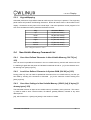
5.5.1.
Turn ON General Purpose Output (GPO) (254 99 [gpo#] 253)
User may use the GPOs to turn on other external devices, mechanical relays or electronic devices.
[gpo#] specifies which GPO is using. It can be either 0 or 1.
Voltage at GPO is +5V when issuing this command. The maximum current which GPO# can
stand for is 100mA, which means the minimum output load should be 50 Ohm. User should take
extremely care on the resistance of the load which GPO# is driving. Drawing exceeding current
will damage the GPO# or even CW12832.
Below is an example of how GPO0 connects to a mechanical relay (Drawing 14). Again, please
make sure the coil resistance is greater than 50 Ohm.
0xfe [start byte],
0x63 [GPO ON command],
0x00,
0xfd[stop byte]
Initially, GPO0 is in low or ground state. The 5V relay is off as the coil voltage is 0V. GPO0
switches to 5V after the above command is issued. The coil voltage now is 5V and Contact 1 and
Contact 2 are connected. Notice the diode connected in between GPO0 and GND is to prevent
any back emf from damaging the relay. In addition, a polarized capacitor 4.7μ F can also be added
between GPO0 and GND in order to reduce any noise spike voltage and back flow of current.
CW12832 User Manual
28
CW12832
GPO0
Display
GND
JP1
5V GND
5V Relay
Contact1
Contact2
Drawing 10 Typical application of GPO.
5.5.2.
Turn OFF
General Purpose Output (GPO) (254 100 [gpo#] 253)
GPO# will pull to low (ground) if user sends this command. [gpo#] is the GPO number which can
be either 0 or 1.
5.5.3.
Read Status of General Purpose Input (GPI) (254 101 [gpi#] 253)
CW12832 has 2 GPIs provided to read the status back through this command. These 2 GPIs are
internally pulled up by 5V in CW12832. A '0' will be sent back to the host if the GPI# has a high input, which maybe a TTL 5V or a TTL voltage greater than 2V, or left unconnected. On the other
hand, a '1' will be sent back if the GPI# has a low input, which may be ground or a TTL voltage level lower than 0.8V. However, only TTL inputs are allowed to connected to these GPIs. Table 6 below shows the DC characteristics of the GPI.
User should notice it may burn the GPIs or
CW12832 if the input source is not TTL level.
Parameters
Symbol
Min
Typ
Max
Unit
Input HIGH voltage
VIH
2
5
7
V
Input LOW voltage
VIL
0
0.8
V
Input HIGH current (VIN = 2.7V)
IIH
20
μ A
Input HIGH current (VIN = 7V)
IIH
0.1
mA
Input Low current (VIN = 0.4)
IIL
-0.4
mA
Table 5 DC characteristics of GPI
CW12832 User Manual
29
CW12832
Display
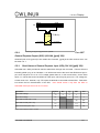
Drawing 15 and 16 showed below describe how the GPI0 is connected with 2 different input
sources. In drawing 15, GPI0 reads low when the pin CONTROL of the relay is activated. Thus,
user will read a '1' if the following command is sent to CW12832,
0xfe [start byte],
0x65 [GPI read command],
0x00,
0xfd[stop byte]
On the other hand, it reads a '0' if the pin CONTROL is low. Similarly, GPI0 reads the output of the
TTL gate and feedbacks the complement of it.
Input
CONTROL
+5V
5V Relay 5V GND
Input
Output
TTL gate
GND
JP1
JP1
GPI0
GND
Drawing 11 Relay connected to GPI0.
CW12832 User Manual
GPI0
+5V
GND
Drawing 12 TTL gate connected to GPI0.
30
CW12832
Display
Chapter 6. Command Summary
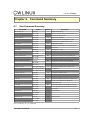
6.1.
Text Command Summary
Command
Auto line wrap on
Syntax
FE 43 FD
Default
off
254 67 253
Character will wrap to first position of next line if
254 'C' 253
Auto line wrap off
Auto scroll on
FE 44 FD
it reaches the end of a line.
off
Disables line wrapping.
254 68 253
Character will go to the first position of the
254 'D' 253
original line if it reaches the end of a line.
FE 51 FD
off
254 81 253
FE 52 FD
Enables line scrolling.
Shift entire screen up by 1 line to make room for
254 'Q' 253
Auto scroll off
Description
Enables line wrapping.
the last row.
off
Disables line scrolling
N/A
Sets the text insertion point to [col] and [row].
N/A
Sets the text insertion point to [0] and [0].
off
Turns on the underline cursor and sets it at
254 82 253
254 'R' 253
Set text insertion point
FE 47 [col] [row] FD
254 71 253
254 'G' 253
Set text insertion point home
FE 48 FD
254 72 253
254 'H' 253
Underline cursor on
FE 4A [col] [row] FD
254 74 [col] [row] 253
[col] and [row].
254 'J' [col] [row] 253
Underline cursor off
FE 4B FD
off
Turns off the underline cursor.
N/A
Moves the underline cursor to left. It will move to
254 75 253
254 'K' 253
Cursor left
Cursor right
FE 4C FD
254 76 253
the end of the same line if it reaches the
254 'L' 253
beginning of a line.
FE 4D FD
N/A
254 77 253
to the beginning of the same line if it reaches the
254 'M' 253
Inverse text on
FE 66 FD
Moves the underline cursor to right. It will move
end of a line.
off
Text inverse on.
off
Text inverse off.
254 102 253
254 'f' 253
Inverse text off
FE 67 FD
254 103 253
254 'g' 253
Table 6 Summary for text commands
CW12832 User Manual
31
CW12832
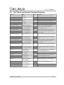
6.2.
Display
Bar Charts and Graphic Command Summary
Command
Syntax
Default
Description
Initial thick vertical bar graph
FE 76 FD
on
Initializes 5 pixels width as the vertical bar.
off
Initializes 2 pixels width as the vertical bar.
N/A
Defines custom character. [cc] goes from [
254 118 253
254 'v' 253
Initial thin vertical bar graph
FE 73 FD
254 115 253
254 's' 253
Define custom character
Draw vertical bar graph
Erase vertical bar graph
FE 4E [cc] [6 bytes] FD
254 104 [cc] [6 bytes] 253
[0x01] to 0x10]. The other 6 bytes are
254 'N' [cc] [6 bytes] 253
described in section 4.2.7
FE 3D [col] [height] FD
N/A
Draws vertical bar at position [col] of the last
254 61 [col] [height] 253
row with height [height]. [height] ranges from
254 '=' [col] [height] 253
[0x00] to [0x20].
FE 2D [col] [height] FD
N/A
Erases vertical bar at position [col] of the last row
with
Draw horizontal bar graph
Erase horizontal bar graph
254 45 [col] [height] 253
height [height]. [height] ranges from [0x00] to
254 '-' [col] [height] 253
[0x20].
FE 7C [col] [row] [len] FD
N/A
Draws horizontal bar at position [col] and [row]
254 124 [col] [row] [len] 253
With length [length]. [length] ranges from
254 '|' [col] [row] [len] 253
[[0x00] to 0x7A].
FE 2B [col] [row] [len] FD
N/A
Erases horizontal bar at position [col] and [row]
with
Put pixel
254 43 [col] [row] [len] 253
length [length]. [length] ranges from [0x00] to
254 '+' [col] [row] [len] 253
[0x7A].
FE 70 [x] [y] FD
N/A
254 112 [x] [y] 253
Draws a pixel at location (x,y). x ranges from 0
to 121 and y ranges from 0 to 31.
254 'p' [x] [y] 253
Clear pixel
FE 71 [x] [y] FD
N/A
254 113 [x] [y] 253
Clears a pixel at location (x, y). x ranges from
0 to 121 and y ranges from 0 to 31.
254 'q' [x] [y] 253
Draw byte
FE 3E [x] [row] [byte] [4
N/A
Draws a byte at location (x, row). x ranges
dummy bytes] FD
254 62 [x] [row] [byte] [4
from 0 to 121 and row ranges from 0 to 3.
dummy bytes] 253
254 '>' [x] [row] [byte] [4
dummy bytes] 253
Table 7 Summary for graphic commands
CW12832 User Manual
32
CW12832
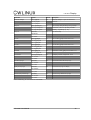
6.3.
Display
Miscellaneous Command Summary
CW12832 User Manual
33
CW12832
Display
Command
Syntax
Default
Description
Read Model Number
FE 30 FD
N/A
Reads 2 bytes back from LCD
N/A
Reads 2 bytes back from LCD
N/A
Resets CW12832
off
Clears screen of LCD and places the text
254 48 253
254 '0' 253
Read Firmware Version
FE 31 FD
254 49 253
254 '1'’ 253
Soft Reset
FE 56 FD
254 86 253
254 'V' 253
Clear display
FE 58 FD
254 88 253
insertion point to top left.
254 'X' 253
Backlight on
FE 42 FD
on
Turns on the backlight.
off
Turns off the backlight.
N/A
Adjust LED brightness. [brightness] ranges from
254 66 253
254 'B' 253
Backlight off
FE 46 FD
254 70 253
254 'F' 253
Backlight brightness
FE 41 [brightness] FD
254 64 [brightness] 253
1 to 7.
254 'A' [brightness] 253
Auto key hole on
FE 32 FD
off
Auto key hold on.
off
Auto key hold off.
19200
Sets RS232 port speed. Refer to section 5.1.6
254 50 253
254 ‘2’ 253
Auto key hold off
FE 33 FD
254 51 253
254 ‘3’ 253
Set RS232 port speed
FE 39 [speed] FD
254 57 [speed] 253
for details.
254 '9' [speed] 253
Save user defined characters
FE 4F [cc] FD
N/A
254 79 [cc] 253
Save user defined characters. [cc] ranges from
1 to 16.
254 'O' [cc] 253
Load user defined characters
FE 50 [cc] FD
N/A
254 80 [cc] 253
Load user defined characters. [cc] ranges from
1 to 16.
254 'P' [cc] 253
Save user settings
FE 53 [ud] [4 bytes] [2
N/A
Save user settings. User is required to save 4
dummy bytes] FD
bytes at a time.
254 83 [ud] [4 bytes] [2
[ud] ranges from 1 to 8.
dummy bytes] 253
254 'S' [ud] [4 bytes] [2
dummy bytes] 253
CW12832 User Manual
34
CW12832
Display
Command
Syntax
Default
Description
Read user settings
FE 54 [ud] FD
N/A
Read user settings. 4 bytes are returned at
254 84 [ud] 253
each time.
254 'T' [ud] 253
Relay On
FE 61 [timeout] FD
off
254 97 [timeout] 253
0. However, it will on for [timeout] seconds if
254 'a' [timeout] 253
Relay off
FE 62 FD
Turn on relay. Relay will always on if [timeout] =
[timeout] > 0. [timeout] = {1..10}
off
Turn off the relay.
off
Turn on GPO. [gpo#] must be either 0 or 1.
off
Turn off GPO. [gpo#] must be either 0 or 1.
N/A
Read status of GPI. [gpi#] must be either 0 or 1.
N/A
Set display contrast, range 0x00 - 0x1C
N/A
Save current screen as boot-up logo
N/A
Draw the boot-up logo on display
N/A
Restore factory default boot-up logo.
254 98 253
254 'b' 253
GPO on
FE 63 [gpo#] FD
254 99 [gpo#] 253
254 'c' [gpo#] 253
GPO off
FE 64 [gpo#] FD
254 100 [gpo#] 253
254 'd' [gpo#] 253
Read GPI
FE 65 [gpi#] FD
254 101 [gpi#] 253
Set Contrast
FE 68 [contrast] FD
254 104 253
254 'h' 253
Save boot-up logo
FE 6A FD
254 105 253
254 'i' 253
Display boot-up logo
FE 69 FD
254 106 253
254 'j' 253
Restore factory default logo
FE 6B FD
254 107 253
254 'k' 253
Table 8 Summary for miscellaneous commands
CW12832 User Manual
35
CW12832
6.4.
Display
Text Mode Coordinates
Column 0 & Row 0
Column 20 & Row 0
Column 0 & Row 3
Column 20 & Row 3
CW12832 User Manual
36
CW12832
Display
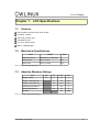
Chapter 7. LCD Specifications
7.1.
Features
Full dot-matrix structure with 128 x 32 dots
1/32 Duty, 1/5 bias
STN LCD, positive, gray
Transflective LCD
6 o’ clock viewing angle
Built-in LED backlight
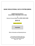
7.2.
Mechanical Specifications
Item
Detail
Unit
Outline dimension
Standard 1 PC Bay size
Viewing area
46.0 x 10.53
mm
Active area
42.21 x 10.53
mm
Table 9 Mechanical Specifications
7.3.
Absolute Maximum Ratings
Item
Min.
Typ.
Max.
Unit
4.5
5
5.5
V
Supply current (BL off)
1
1.5
mA
Supply current (BL on)
121
121.5
mA
Operating temperature
0
50
o
C
-20
70
o
C
Supply voltage
Storage temperature
Humidity
90
%RH
Table 10 Absolute Maximum Ratings
CW12832 User Manual
37
CW12832
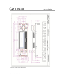
Display
Drawing 13 Mechanical dimensions
CW12832 User Manual
38
CW12832
Display
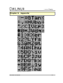
Chapter 8. Appendix
Drawing 14 Default characters.
CW12832 User Manual
39