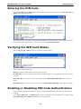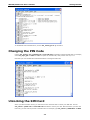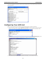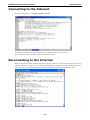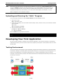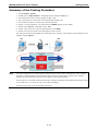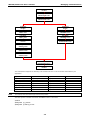
1
W315A/325A Linux User’s Manual First Edition, August 2010 www.moxa.com/product © 2010 Moxa Inc. All rights reserved. Reproduction without permission is prohibited. W315A/325A Linux User’s Manual The software described in this manual is furnished under a license agreement and may be used only in accordance with the terms of that agreement. Copyright Notice Copyright ©2010 Moxa Inc. All rights reserved. Reproduction without permission is prohibited. Trademarks The MOXA logo is a registered trademark of Moxa Inc. All other trademarks or registered marks in this manual belong to their respective manufacturers. Disclaimer Information in this document is subject to change without notice and does not represent a commitment on the part of Moxa. Moxa provides this document as is, without warranty of any kind, either expressed or implied, including, but not limited to, its particular purpose. Moxa reserves the right to make improvements and/or changes to this manual, or to the products and/or the programs described in this manual, at any time. Information provided in this manual is intended to be accurate and reliable. However, Moxa assumes no responsibility for its use, or for any infringements on the rights of third parties that may result from its use. This product might include unintentional technical or typographical errors. Changes are periodically made to the information herein to correct such errors, and these changes are incorporated into new editions of the publication. Technical Support Contact Information www.moxa.com/support Moxa Americas Moxa China (Shanghai office) Toll-free: 1-888-669-2872 Toll-free: 800-820-5036 Tel: +1-714-528-6777 Tel: +86-21-5258-9955 Fax: +1-714-528-6778 Fax: +86-10-6872-3958 Moxa Europe Moxa Asia-Pacific Tel: +49-89-3 70 03 99-0 Tel: +886-2-8919-1230 Fax: +49-89-3 70 03 99-99 Fax: +886-2-8919-1231 Table of Contents 1. Introduction ...................................................................................................................................... 1-1 Overview ........................................................................................................................................... 1-2 Software Architecture .......................................................................................................................... 1-2 Journaling Flash File System (JFFS2) ............................................................................................. 1-3 Software Package ........................................................................................................................ 1-4 2. Getting Started.................................................................................................................................. 2-1 Powering on the W315A/325A .............................................................................................................. 2-2 Connecting the W315A/325A to a PC ..................................................................................................... 2-2 Serial Console ............................................................................................................................. 2-2 SSH Console ............................................................................................................................... 2-3 Configuring the Ethernet Interface ........................................................................................................ 2-3 Modifying Network Settings with the Serial Console ......................................................................... 2-3 Modifying Network Settings over the Network ................................................................................. 2-4 GPRS Networks .................................................................................................................................. 2-4 Setting Up the Wireless Module ............................................................................................................ 2-4 Configuring the SIM Card ..................................................................................................................... 2-4 Entering the PIN Code ......................................................................................................................... 2-5 Verifying the SIM Card Status .............................................................................................................. 2-5 Enabling or Disabling PIN Code Authentication........................................................................................ 2-5 Changing the PIN Code........................................................................................................................ 2-6 Unlocking the SIM Card ....................................................................................................................... 2-6 Configuring Your APN List .................................................................................................................... 2-7 Connecting to the Internet ................................................................................................................... 2-8 Reconnecting to the Internet ................................................................................................................ 2-8 Disconnecting from the Internet ........................................................................................................... 2-9 Detecting an Internet Connection Error ................................................................................................. 2-9 Sending and Reading an SMS Message .................................................................................................. 2-9 Deleting an SMS Message .................................................................................................................. 2-10 SD Socket for Storage Expansion ........................................................................................................ 2-10 Test Program—Developing Hello.c ....................................................................................................... 2-11 Installing the Tool Chain (Linux) .................................................................................................. 2-11 Checking the Flash Memory Space ............................................................................................... 2-11 Compiling Hello.c ...................................................................................................................... 2-12 Uploading and Running the “Hello” Program ................................................................................. 2-13 Developing Your First Application ........................................................................................................ 2-13 Testing Environment .................................................................................................................. 2-13 Compiling tcps2.c ...................................................................................................................... 2-14 Uploading and Running the “tcps2-release” Program ...................................................................... 2-15 Summary of the Testing Procedure .............................................................................................. 2-17 3. Managing Embedded Linux ................................................................................................................ 3-1 System Version Information ................................................................................................................. 3-2 System Image Backup......................................................................................................................... 3-2 Upgrading the Firmware ............................................................................................................... 3-2 Loading Factory Defaults .............................................................................................................. 3-4 Enabling and Disabling Daemons .......................................................................................................... 3-4 Starting a Program Automatically at Run-Level ....................................................................................... 3-6 Adjusting the System Time .................................................................................................................. 3-7 Setting the Time Manually ............................................................................................................ 3-7 NTP Client .................................................................................................................................. 3-8 Updating the Time Automatically ................................................................................................... 3-8 Cron—Daemon for Executing Scheduled Commands ................................................................................ 3-9 4. Managing Communications................................................................................................................ 4-1 Telnet/FTP ......................................................................................................................................... 4-2 DNS .................................................................................................................................................. 4-2 Web Service—Apache .......................................................................................................................... 4-3 Installing PHP for Apache Web Server ................................................................................................... 4-4 IPTABLES........................................................................................................................................... 4-7 Observe and Erase Chain Rules ..................................................................................................... 4-9 Define Policy for Chain Rules......................................................................................................... 4-9 Append or Delete Rules .............................................................................................................. 4-10 NAT ................................................................................................................................................ 4-10 NAT Example ............................................................................................................................ 4-11 Enabling NAT at Bootup.............................................................................................................. 4-11 Dial-up Service—PPP ......................................................................................................................... 4-12 How to Check the Connection ..................................................................................................... 4-13 Setting up a Machine for Incoming PPP Connections ...................................................................... 4-14 PPPoE.............................................................................................................................................. 4-15 GPRS Connection .............................................................................................................................. 4-17 Configuring the options for pppd ................................................................................................. 4-17 Configuring the AT commands .................................................................................................... 4-18 Example: Selecting the radio band .............................................................................................. 4-18 NFS (Network File System) ................................................................................................................ 4-18 Setting up the W315A/325A as an NFS Client ............................................................................... 4-19 Mail................................................................................................................................................. 4-19 SNMP .............................................................................................................................................. 4-19 5. Development Tool Chains .................................................................................................................. 5-1 Linux Tool Chain ................................................................................................................................. 5-2 Steps for Installing the Linux Tool Chain......................................................................................... 5-2 Compiling an Application .............................................................................................................. 5-2 On-Line Debugging with GDB ........................................................................................................ 5-3 6. Programmer's Guide ......................................................................................................................... 6-1 Before Programming Your Embedded System ......................................................................................... 6-2 Caution Required when Using File Systems ..................................................................................... 6-2 Using a RAM File System instead of a Flash File System ................................................................... 6-2 Flash Memory Map .............................................................................................................................. 6-2 Device API ......................................................................................................................................... 6-2 RTC (Real Time Clock) ......................................................................................................................... 6-3 Buzzer............................................................................................................................................... 6-3 WDT (Watch Dog Timer) ...................................................................................................................... 6-3 UART ................................................................................................................................................ 6-6 C Library ........................................................................................................................................... 6-7 7. Software Lock ................................................................................................................................... 7-1 A. System Commands ............................................................................................................................ A-1 Common Linux Utility Commands .........................................................................................................A-2 File Manager ...............................................................................................................................A-2 Editor ........................................................................................................................................A-2 Network .....................................................................................................................................A-2 Process ......................................................................................................................................A-2 Other .........................................................................................................................................A-3 Special Moxa Utilities ..........................................................................................................................A-3 1 1. Introduction The W315A/325A series of wireless RISC-based embedded computers feature a GSM/GPRS module, RS-232/422/485 serial ports, and an Ethernet port in a small, rugged chassis, and come with an SD slot for external storage expansion. The W315A/325A series embedded computers are ideal for diverse, machine-to-machine embedded applications. The computers enable the wireless operation of network and serial devices that are traditionally wired, and can handle transparent data transfers, numerical computing, protocol conversion, data processing, and even data encryption. The W315A/325A will make it easier to build embedded systems for distributed peer-to-peer communication, turn wired devices into wireless devices, and introduce higher mobility and more intelligence to your system. In this chapter, we cover the various capabilities of the W315A/325A series embedded computers. The following topics are covered in this chapter: Overview Software Architecture Journaling Flash File System (JFFS2) Software Package W315A/325A Linux User's Manual Introduction Overview The W315A/325A wireless embedded computers come with a quad band 850/900/1800/1900 MHz GSM/GPRS module built in for long-range communications. The computers use a Moxa ART 192 Mhz RISC CPU. Unlike the X86 CPU, which uses a CISC design, the RISC architecture and modern semiconductor technology provide these embedded computers with a powerful computing engine and communication functions, but without generating a lot of heat. A 16 MB NOR Flash ROM and on-board 32 MB SDRAM give you enough memory to install your application software directly on the embedded computer. In addition, a LAN port is built right into the RISC CPU. This network capability, in combination with the ability to control serial devices, makes the W300 Series ideal as communication platforms for data acquisition and industrial control applications. The pre-installed Linux operating system (OS) provides an open software operating system for your software program development. Software written for desktop PCs can be easily ported to the computer with a GNU cross compiler, without needing to modify the source code. The OS, device drivers (e.g., serial and buzzer control), and your own applications, can all be stored in the NOR Flash. Software Architecture The Linux operating system that is pre-installed in the W315A/325A follows the standard Linux architecture, making it easy to accept programs that follow the POSIX standard. Program porting is done with the GNU Tool Chain provided by Moxa. In addition to Standard POSIX APIs, device drivers for USB storage, buzzer and Network controls, and UART are also included with the Linux OS. The W315A/325A’s built-in Flash ROM is partitioned into Boot Loader, Linux Kernel, Root File System, and User directory partitions. In order to prevent user applications from crashing the Root File System, the W315A/325A computers use a specially designed Root File System with Protected Configuration for emergency use. This Root File System comes with serial and Ethernet communication capability for users to load the Factory Default Image file. The user directory saves the user’s settings and applications. To improve system reliability, the W315A/325A has a built-in mechanism that prevents the system from crashing. When the Linux kernel boots up, the kernel will mount the root file system for read only, and then enable services and daemons. During this time, the kernel will start searching for system configuration parameters with rc or inittab. 1-2 W315A/325A Linux User's Manual Introduction Normally, the kernel uses the Root File System to boot up the system. The Root File System is protected, and cannot be changed by the user. This type of setup creates a “safe” zone. For more information about the memory map and programming, refer to Chapter 6, Programmer’s Guide. Journaling Flash File System (JFFS2) The Root File System and User Directory in the flash memory are formatted with the Journaling Flash File System (JFFS2). The formatting process places a compressed file system in the flash memory. This operation is transparent to the user. The Journaling Flash File System (JFFS2), which was developed by Axis Communications in Sweden, puts a file system directly on the flash, instead of emulating a block device. It is designed for use on flash-ROM chips and recognizes the special write requirements of a flash-ROM chip. JFFS2 implements wear-leveling to extend the life of the flash disk, and stores the flash directory structure in the RAM. A log-structured file system is maintained at all times. The system is always consistent, even if it encounters crashes or improper power-downs, and does not require fsck (file system check) on boot-up. JFFS2 is the newest version of JFFS. It provides improved wear-leveling and garbage-collection performance, improved RAM footprint and response to system-memory pressure, improved concurrency and support for suspending flash erases, marking of bad sectors with continued use of the remaining good sectors (enhancing the write-life of the devices), native data compression inside the file system design, and support for hard links. The key features of JFFS2 are: • Targets the Flash ROM Directly • Robustness • Consistency across power failures • No integrity scan (fsck) is required at boot time after normal or abnormal shutdown • Explicit wear leveling • Transparent compression Although JFFS2 is a journaling file system, it may not prevent the loss of data. The file system will remain in a consistent state across power failures and will always be mountable. However, if the board is powered down during a write then the incomplete write will be rolled back on the next boot, but writes that have already been completed will not be affected. Additional information about JFFS2 is available at: http://sources.redhat.com/jffs2/jffs2.pdf http://developer.axis.com/software/jffs/ http://www.linux-mtd.infradead.org/ 1-3 W315A/325A Linux User's Manual Introduction Software Package Boot Loader Moxa private (V1.2) Kernel Linux 2.6.9 Protocol Stack ARP, PPP, CHAP, PAP, IPv4, ICMP, TCP, UDP, DHCP, FTP, SNMP V1/V3, HTTP, NTP, File System JFFS2, NFS, Ext2, Ext3, VFAT/FAT OS shell command Bash Busybox Linux normal command utility collection NFS, SMTP, SSH 1.0/2.0, SSL, Telnet, PPPoE, OpenVPN Utilities tinylogin login and user manager utility telnet telnet client program ftp FTP client program smtpclient email utility scp Secure file transfer Client Program Daemons pppd dial in/out over serial port daemon egprsagent Sms/sim/gprs controlling agent snmpd snmpd agent daemon inetd TCP server manager program ftpd ftp server daemon apache web server daemon sshd secure shell server openvpn virtual private network openssl open SSL Linux Tool Chain Gcc (V3.3.2) C/C++ PC Cross Compiler GDB (V5.3) Source Level Debug Server Glibc (V2.2.5) POSIX standard C library 1-4 2 2. Getting Started In this chapter, we explain how to connect the W315A/325A, turn on the power, get started programming, and how to use the W315A/325A’s other functions. The following topics are covered in this chapter: Powering on the W315A/325A Connecting the W315A/325A to a PC Serial Console SSH Console Configuring the Ethernet Interface Modifying Network Settings with the Serial Console Modifying Network Settings over the Network GPRS Networks Setting Up the Wireless Module Configuring the SIM Card Entering the PIN Code Verifying the SIM Card Status Enabling or Disabling PIN Code Authentication Changing the PIN Code Unlocking the SIM Card Configuring Your APN List Connecting to the Internet Reconnecting to the Internet Disconnecting from the Internet Detecting an Internet Connection Error Sending and Reading an SMS Message Deleting an SMS Message SD Socket for Storage Expansion Test Program—Developing Hello.c Installing the Tool Chain (Linux) Checking the Flash Memory Space Compiling Hello.c Uploading and Running the “Hello” Program Developing Your First Application Testing Environment Compiling tcps2.c Uploading and Running the “tcps2-release” Program Summary of the Testing Procedure W315A/325A Linux User's Manual Getting Started Powering on the W315A/325A Connect the SG wire to the shielded contact located on the left of the W315A/325A’s top panel, and then power on the computer by connecting it to the power adaptor. It takes about 30 to 60 seconds for the system to boot up. Once the system is ready, the Ready LED will light up. NOTE After connecting the W315A/325A to the power supply, it will take about 30 to 60 seconds for the operating system to boot up. The green Ready LED will not turn on until the operating system is ready. ATTENTION This product is intended to be supplied by a Listed Power Unit and output marked with “LPS” and rated 12-48 VDC, 1.2 A (minimum requirements). Connecting the W315A/325A to a PC There are two ways to connect the W315A/325A to a PC: through the serial console port or by SSH Console over the network. Serial Console The serial console gives users a convenient way of connecting to the W315A/325A. This method is particularly useful when using the computer for the first time, or when you do not know either of the W315A/325A’s two IP addresses. Use the serial console port settings shown below. Baudrate 115200 bps Parity None Data bits 8 Stop bit 1 Flow Control None Terminal VT100 Once the connection is established, the following window will open. 2-2 W315A/325A Linux User's Manual Getting Started SSH Console The W315A/325A supports an SSH Console to provide users with better security options. Use this option only if you know exactly which IP address has been assigned from your DHCP server; otherwise, you should connect through the serial console and change it to a static IP address before using it. Windows Users Click on the link http://www.chiark.greenend.org.uk/~sgtatham/putty/download.html to download PuTTY (free software) to set up an SSH console for the W315A/325A in a Windows environment. The following figure shows a simple example of the configuration that is required. Linux Users From a Linux machine, use the “ssh” command to access the W315A/325A’s console utility via SSH. #ssh 192.168.27.122 Select yes to complete the connection. [root@localhost root]# ssh 192.168.27.122 The authenticity of host ‘192.168.27.122 (192.168.27.122)’ can’t be established. RSA key fingerprint is 8b:ee:ff:84:41:25:fc:cd:2a:f2:92:8f:cb:1f:6b:2f. Are you sure you want to continue connection (yes/no)? yes_ NOTE SSH provides better security compared to Telnet for accessing the W315A/325A’s console utility over the network. Configuring the Ethernet Interface The network settings of the W315A/325A can be modified with the serial console, or online over the network. Modifying Network Settings with the Serial Console In this section, we use the serial console to configure the network settings of the target computer. 2-3 W315A/325A Linux User's Manual Getting Started 1. Follow the instructions given in a previous section to access the Console Utility of the target computer through the serial console port, and then type #cd /etc/network to change directories. 2. Type #vi interfaces to use vi editor to edit the network configuration file. You can configure the Ethernet ports of the W315A/325A for dynamic (DHCP) IP addresses. 3. After the boot settings of the LAN interface have been modified, issue the following command to activate the LAN settings immediately: #/etc/init.d/networking restart NOTE After changing the IP settings, use the networking restart command to activate the new IP address. Modifying Network Settings over the Network IP settings can be activated over the network, but the new settings will not be saved to the flash ROM without modifying the file /etc/network/interfaces. For example, type the command #ifconfig eth0 192.168.27.125 to change the LAN IP address to 192.168.27.125. root@Moxa:~# ifconfig eth0 192.168.27.125 root@Moxa:~# _ GPRS Networks The W315A/325A embedded computers include a GSM/GPRS module for wireless communication. The module can be used to transmit data over a GPRS network. Setting Up the Wireless Module Before using the W315A/325A, make sure the SIM card is properly installed and the antenna is connected (refer to the W315A/325A Hardware User’s Manual for details). Note that the SIM card must be installed when the embedded computer is powered off. The LED indicators on the front panel can be used to check the signal strength. A process running in the background, called “egprsagent,” is responsible for this task. Configuring the SIM Card NOTE: Make sure you have the correct PIN code. After three failed attempts to enter the PIN code, the SIM card will be locked, and you will need to use the PUK code to unlock the SIM card. After ten failed attempts to enter the PUK code, the SIM card will be deactivated and will no longer be operable. 2-4 W315A/325A Linux User's Manual Getting Started Entering the PIN Code Use the sim_input_pin –p PIN code command to enter the PIN code. For example, type sim_input_pin –p 0000 to enter the PIN code 0000. To save the PIN code and perform automatic authentication for a GPRS connection, add –s after the PIN code. To disable automatic authentication, remove the system file /etc/chatscripts/cpin. Verifying the SIM Card Status Use the sim_get_pin_status command to check the SIM card status. There are four possible responses: Ready: Your W315A/325A wireless module is ready to work. No SIM card: You need to insert the SIM card into the W315A/325A, or your SIM card may not be inserted correctly. Need PIN code: You need to enter the correct PIN code. See Entering the PIN Code in this section for details. Need PUK code: You need to enter the PUK code: See Unlocking the SIM Card in this section for details. Enabling or Disabling PIN Code Authentication You can enable PIN code authentication to prompt for PIN code authentication whenever the W315A/325A boots up. Use the sim_enable_pin –e –p PIN code command to enable PIN code authentication. For example, enter sim_enable_ping –e –p 0000 to activate PIN code authentication. 2-5 W315A/325A Linux User's Manual Getting Started To disable PIN code authentication, use the sim_enable_pin-d –p command. Changing the PIN Code Use the sim_change_pin -o old PIN code –n new PIN code command to change the PIN code. For example, enter sim_input_pin –o 0000 –n 1111 to replace an old PIN code, 0000, with a new one, 1111. Note that you must enable PIN code authentication to change the PIN code. Unlocking the SIM Card When your SIM has been locked, you will need to enter the PUK code to unlock your SIM card. Use the sim_unlock –p PUK code –n new PIN code command to unlock your card. Note that when you enter the PUK code, you also need to provide a new PIN code. For example, type sim_unlock –p 80364944 –n 0000. 2-6 W315A/325A Linux User's Manual Getting Started In this case, 80364944 is the PUK code, and 0000 is the new PIN code. Use this new PIN code the next time the W315A/325A starts. Configuring Your APN List Before you start connecting to the Internet, take the following steps to configure the APN list: 1. Check the operator’s name by using the egprscmd –t at+cops? command. However, make sure you have entered a correct PIN code or disabled PIN code authentication so you can check the operator's name. 2. Next, you need to add the operator’s name and APN name in the file /etc/chatscripts/apn_list. In this case, we know that the operator is Chunghwa Teleco. Add this information in the file. 3. If the operator has provided the user and password information, you can edit them in this file. 2-7 W315A/325A Linux User's Manual Getting Started Connecting to the Internet To create a connection, use the gprs_connect command. For detailed command syntax, type gprs_connect –h. While connected, you can use the gprs_connection_status command to check the connection status. Reconnecting to the Internet When an internet connection gets disconnected, use the gprs_reconnect –t second command to reconnect. For example, enter gprs_reconnect –t 120 to direct the W315A/325A to attempt to reconnect to the Internet every 120 seconds. If you do not provide the time interval, the default value of 60 seconds will be used. 2-8 W315A/325A Linux User's Manual Getting Started Use the gprs_reconnect –h command for more details. If you have enabled PIN checking, issue the command sim_input_pin -p xxxx -s to save the PIN code information in the system. Issue the command gprs_disconnect -r to disable the reconnection setting. Disconnecting from the Internet To disconnect from the Internet, use the gprs_disconnect command. After a few seconds, the embedded computer will disconnect from the GPRS network. A notification message will NOT be displayed. Detecting an Internet Connection Error To diagnose a connection problem, use the gprs_diagnose command. This utility will execute a series of steps to check whether or not the configuration is correct. Most connection problems can be indentified with this command. Sending and Reading an SMS Message To send an SMS message, use the sms_send_text_msg command. For example, enter sms_send_text_msg –n 0988713219 –t “hello! This is an SMS test.” to send the message “hello! This is an SMS test.” to the phone number 0988693141. 2-9 W315A/325A Linux User's Manual Getting Started To read an SMS message, use the sms_read_text_msg –i command. For example, sms_read_text_msg –i 1, will display the first SMS message. Deleting an SMS Message To delete an SMS message, use the sms_remove_msg command. For example, the sms_remove_msg –i 1 command will delete the first SMS message. SD Socket for Storage Expansion The W315A/325A models have an SD socket for storage expansion. The SD slot allows users to plug in a Secure Digital (SD) memory card compliant with the SD 1.0 standard for up to 1 GB of additional memory space, or a Secure Digital High Capacity (SDHC) memory card compliant with the SD 2.0 standard for up to 16 GB of additional memory space. Refer to the W315A/325A Hardware User’s Manual to see how to install the SD card. After installing an SD card, the SD card will be mounted at /mnt/sd. 2-10 W315A/325A Linux User's Manual Getting Started Test Program—Developing Hello.c In this section, we use the standard “Hello” programming example to illustrate how to develop a program for the W315A/325A. In general, program development involves the following seven steps. Step 1: Connect the W315A/325A to a Linux PC. Step 2: Install Tool Chain (GNU cross Compiler & glibc). Step 3: Set the cross compiler and glibc environment variables. Step 4: Code and compile the program. Step 5: Download the program to the W315A/325A via FTP or NFS. Step 6: Debug the program > If bugs are found, return to Step 4. > If no bugs are found, continue with Step 7. Step 7: Back up the user directory (distribute the program to additional W315A/325A units if needed). Installing the Tool Chain (Linux) The Linux Operating System must be pre-installed in the PC before installing the W315A/325A GNU Tool Chain. Fedora core or compatible versions are recommended. The Tool Chain requires approximately 200 MB of hard disk space on your PC. The W315A/325A Tool Chain software is located on the W315A/325A CD. To install the Tool Chain, insert the CD in your PC and then issue the following commands: #mount /dev/cdrom /mnt/cdrom #sh /mnt/cdrom/tool-chain/linux/install.sh The Tool Chain will be installed automatically on your Linux PC within a few minutes. Before compiling the program, be sure to set the following path first, since the Tool Chain files, including the compiler, link, library, and include files are located in this directory. PATH=/usr/local/arm-linux/bin:$PATH Setting the path allows you to run the compiler from any directory. Checking the Flash Memory Space If the flash memory is full, you will not be able to save data to the Flash ROM. Use the following command to calculate the amount of “Available” flash memory: />df –h 2-11 W315A/325A Linux User's Manual Getting Started If there isn’t enough “Available” space for your application, you will need to delete some existing files. To do this, connect your PC to the W315A/325A with the console cable, and then use the console utility to delete the files from the W315A/325A’s flash memory. To check the amount of free space available, look at the directories in the read/write directory /dev/mtdblock3. Note that the directories /home and /etc are both mounted in the directory /dev/mtdblock3. NOTE If the flash memory is full, you will need to free up some memory space before saving files to the Flash ROM. Compiling Hello.c The package CD contains several example programs. Here we use Hello.c as an example to show you how to compile and run your applications. Type the following commands from your PC to copy the files used for this example from the CD to your computer’s hard drive: # cd /tmp/ # mkdir example # cp –r /mnt/cdrom/examples/W321.341.315.325.345_IA240.241_UC-7112PLUS_W315A.W325A/* /tmp/example To compile the program, go to the Hello subdirectory and issue the following commands: #cd example/hello #make You should receive the following response: [root@localhost hello]# make /usr/local/arm-linux/bin/arm-linux-gcc –o hello-release hello.c /usr/local/arm-linux/bin/arm-linux-strip –s hello-release /usr/local/arm-linux/bin/arm-linux-gcc –ggdb -o hello-debug hello.c [root@localhost hello]# _ Next, execute hello.exe to generate hello-release and hello-debug, which are described below: hello-release—an ARM platform execution file (created specifically to run on the W315A/325A) hello-debug—an ARM platform GDB debug server execution file (see Chapter 5 for details about the GDB debug tool). 2-12 W315A/325A Linux User's Manual NOTE Getting Started Since Moxa’s tool chain places a specially designed Makefile in the directory /tmp/example/hello, be sure to type the #make command from within that directory. This special Makefile uses the arm-linux-gcc compiler to compile the hello.c source code for the RISC-based environment. If you type the #make command from within any other directory, Linux will use the x86 compiler (for example, cc or gcc). Refer to Chapter 5 to see a Makefile example. Uploading and Running the “Hello” Program Use the following commands to upload hello-release to the W315A/325A via FTP. 1. From the PC, type: #ftp 192.168.3.127 2. Use the bin command to set the transfer mode to Binary mode, and then use the put command to initiate the file transfer: ftp> bin ftp> put hello-release 3. From the W315A/325A, type: # chmod +x hello-release # ./hello-release The word Hello will be printed on the screen. root@Moxa:~# ./hello-release Hello Developing Your First Application We use the tcps2 example to illustrate how to build an application. The procedure outlined in the following subsections will show you how to build a TCP server program plus serial port communication that runs on the W315A/325A. Testing Environment The tcps2 example demonstrates a simple application program that delivers transparent, bi-directional data transmission between the W315A/325A’s serial and Ethernet ports. As illustrated in the following figure, the purpose of this application is to transfer data between PC 1 and the W315A/325A through an RS-232 connection. At the remote site, data can be transferred between the W315A/325A’s Ethernet port and PC 2 over an Ethernet connection. 2-13 W315A/325A Linux User's Manual Getting Started Compiling tcps2.c The source code for the tcps2 example is located on the CD-ROM at CD-ROM://examples/W321.341.315.325.345_IA240.241_UC-7112PLUS_W315A.W325A/ TCPServer2/tcps2.c. Use the following commands to copy the file to a specific directory on your PC. We use the directory /home/w3x5/1st_application/. Note that you need to copy 3 files—Makefile, tcps2.c, tcpsp.c—from the CD-ROM to the target directory. #mount –t iso9660 /dev/cdrom /mnt/cdrom #cp /mnt/cdrom/examples/W321.341.315.325.345_IA240.241_UC-7112PLUS_W315A.W325A/ TCPServer2/tcpsp.c /home/w3x5/1st_application/tcps2.c #cp /mnt/cdrom/ /home/w3x5/1st_application/tcpsp.c #cp /mnt/cdrom/examples/W321.341.315.325.345_IA240.241_UC-7112PLUS_W315A.W325A/ TCPServer2/Makefile /home/w3x5/1st_application/Makefile Type #make to compile the example code: You will get the following response, indicating that the example program compiled successfully. root@server11:/home/w3x5/1st_application [root@server11 1st_application]# pwd /home/w3x5/1st_application [root@server11 1st_application]# 11 total 20 -rw-r—r-- 1 root root 514 Nov 27 11:52 Makefile -rw-r—r-- 1 root root 4554 Nov 27 11:52 tcps2.c -rw-r—r-- 1 root root 6164 Nov 27 11:55 tcps2.c [root@server11 1st_application]# make_ /usr/local/arm-linux/bin/arm-linux-gcc -o tcps2-release tcps2.c /usr/local/arm-linux/bin/arm-linux-strip –s tcps2-release /usr/local/arm-linux/bin/arm-linux-gcc -o tcpsp-release tcpsp.c /usr/local/arm-linux/bin/arm-linux-strip –s tcpsp-release /usr/local/arm-linux/bin/arm-linux-gcc –ggdb -o tcps2-debug tcps2.c /usr/local/arm-linux/bin/arm-linux-gcc –ggdb -o tcpsp-debug tcpsp.c [root@server11 1st_application]# 11 total 92 -rw-r—-r-- 1 root root 514 Nov 27 11:52 Makefile -rwxr-xr—x 1 root root 25843 Nov 27 12:03 tcps2-debug -rwxr—xr-x 1 root root 4996 Nov 27 12:03 tcps2-release -rw-r—-r-- 1 root root 4554 Nov 27 11:52 tcps2.c -rwxr—xr-x 1 root root 26823 Nov 27 12:03 tcpsp-debug -rwxr—xr-x 1 root root 5396 Nov 27 12:03 tcpsp-release -rw-r—-r-- 1 root root 6164 Nov 27 11:55 tcpsp.c [root@server11 1st_application]# Two executable files, tcps2-release and tcps2-debug, are created. tcps2-release—an ARM platform execution file (created specifically to run on the W315A/325A) tcps2-debug—an ARM platform GDB debug server execution file (see Chapter 5 for details about the GDB debug tool). NOTE If you get an error message at this point, it could be because you neglected to put tcps2.c and tcpsp.c in the same directory. The example Makefile we provide is set up to compile both tcps2 and tcpsp into the same project Makefile. Alternatively, you could modify the Makefile to suit your particular requirements. 2-14 W315A/325A Linux User's Manual Getting Started Uploading and Running the “tcps2-release” Program Use the following commands to use FTP to upload tcps2-release to the W315A/325A. 1. From the PC, type: #ftp 192.168.3.127 2. Next, use the bin command to set the transfer mode to Binary, and the put command to initiate the file transfer: ftp> bin ftp> cd home ftp> put tcps2-release root@server11:/home/w3x5/1st_application [root@server11 1st_application]# ftp 192.168.3.127 Connected to 192.168.3.127 220 Moxa FTP server (Version wu-2.6.1(2) Mon Nov 24 12:17:04 CST 2003) ready. 530 Please login with USER and PASS. 530 Please login with USER and PASS. KERBEROS_V4 rejected as an authentication type Name (192.168.3.127:root): root 331 Password required for root. Password: 230 User root logged in. Remote system type is UNIX. Using binary mode to transfer files. ftp> bin 200 Type set to I. ftp> put tcps2-release local: tcps2-release remote: tcps2-release 277 Entering Passive Mode (192.168.3.127.82.253) 150 Opening BINARY mode data connection for tcps2-release. 226 Transfer complete 4996 bytes sent in 0.00013 seconds (3.9e+04 Kbytes/s) ftp> ls 227 Entering Passive Mode (192.168.3.127.106.196) 150 Opening ASCII mode data connection for /bin/ls. -rw------1 root root 899 Jun 10 08:11 bash_history -rw-r--r-1 root root 4996 Jun 12 02:15 tcps2-release 226 Transfer complete ftp> 3. From the W315A/325A, type: # chmod +x tcps2-release # ./tcps2-release & 192.168.3.127 – PuTTY root@Moxa:~# ls –al drwxr—xr-x 2 root root drwxr—xr-x 15 root root -rw------1 root root -rw-r--r-1 root root root@Moxa:~# chmod +x tcps2-release root@Moxa:~# ls -al drwxr—xr-x 2 root root drwxr—xr-x 15 root root 2-15 0 Jun 12 02:14 0 Jan 1 1970 899 Jun 10 08:11 .bash_history 4996 Jun 12 02:15 tcps2-release 0 Jun 12 02:14 0 Jan 1 1970 W315A/325A Linux User's Manual -rw------1 root -rwxr-xr-x 1 root root@Moxa:~# Getting Started root root 899 Jun 10 08:11 .bash_history 4996 Jun 12 02:15 tcps2-release 4. The program should start running in the background. Use the #ps –ef command to check if the tcps2 program is actually running in the background. #ps // use this command to check if the program is running 192.168.3.127 – PuTTY [1]+ Running ./tcps2-release & root@Moxa:~# ps -ef PID Uid VmSize Stat Command 1 root 532 S init [3] 2 root SWN [ksoftirqd/0] 3 root SW< [events/0] 4 root SW< [khelper] 13 root SW< [kblockd/0] 14 root SW [khubd] 24 root SW [pdflush] 25 root SW [pdflush] 27 root SW< [aio/0] 26 root SW [kswapd0] 604 root SW [mtdblockd] 609 root SW [pccardd] 611 root SW [pccardd] 625 root SWN [jffs2_gcd_mtd3] 673 root 500 S /bin/inetd 679 root 3004 S /usr/bin/httpd -k start -d /etc/apache 682 bin 380 S /bin/portmap 685 root 1176 S /bin/sh --login 690 root 464 S /bin/snmpd 694 nobody 3012 S /usr/bin/httpd -k start -d /etc/apache 695 nobody 3012 S /usr/bin/httpd -k start -d /etc/apache 696 nobody 3012 S /usr/bin/httpd -k start -d /etc/apache 697 nobody 3012 S /usr/bin/httpd -k start -d /etc/apache 698 nobody 3012 S /usr/bin/httpd -k start -d /etc/apache 701 root 352 S /bin/reportip 714 root 1176 S -bash 726 root 436 S /bin/telnetd 727 root 1164 S -bash 728 root 1264 S ./tcps2-release 729 root 1592 S ps -ef root@Moxa:~# NOTE Use the kill -9 command for PID 728 to terminate this program: #kill -9 728 2-16 W315A/325A Linux User's Manual Getting Started Summary of the Testing Procedure 1. Compile tcps2.c (#make). 2. Upload and run tcps2-release in the background (#./tcps2-release &). 3. Check that the process is running (#jobs or #ps -ef). 4. Use a serial cable to connect PC1 to the W315A/325A’s serial port 1. 5. Use an Ethernet cable to connect PC2 to the W315A/325A. 6. On PC1: If running Windows, use HyperTerminal (38400, n, 8, 1) to open COMn. 7. On PC2: Type #telnet 192.168.3.127 4001. 8. On PC1: Type some text on the keyboard and then press Enter. 9. On PC2: The text you typed on PC1 will appear on PC2’s screen. The testing environment is illustrated in the following figure. However, note that there are limitations to the example program tcps2.c. NOTE The tcps2.c application is a simple example designed to give users a basic understanding of the concepts involved in combining Ethernet communication and serial port communication. However, the example program has some limitations that make it unsuitable for real-life applications. The serial port is in canonical mode and block mode, making it impossible to send data from the Ethernet side to the serial side (i.e., from PC 2 to PC 1 in the above example). The Ethernet side will not accept multiple connections. 2-17 3 3. Managing Embedded Linux This chapter includes information about version control, deployment, updates, and peripherals. The information in this chapter will be particularly useful when you need to run the same application on several W315A/325A units. The following topics are covered in this chapter: System Version Information System Image Backup Upgrading the Firmware Loading Factory Defaults Enabling and Disabling Daemons Starting a Program Automatically at Run-Level Adjusting the System Time Setting the Time Manually NTP Client Updating the Time Automatically Cron—Daemon for Executing Scheduled Commands W315A/325A Linux User's Manual Managing Embedded Linux System Version Information To determine the hardware capability of your W315A/325A, and what kind of software functions are supported, check the version numbers of your W315A/325A’s hardware, kernel, and user file system. Contact Moxa to determine the hardware version. You will need the Production S/N (Serial number), which is located on the W315A/325A’s bottom label. To check the kernel version, type: #kversion 192.168.3.127 – PuTTY root@Moxa:~# kversion W325A Version 1.0 root@Moxa:~# NOTE The kernel version number shown above is for the factory default configuration. If you download and install the latest firmware version from Moxa’s website, the new kernel version number will be displayed. System Image Backup Upgrading the Firmware The W315A/325A’s bios, kernel, and root file system are combined into one firmware file, which can be downloaded from Moxa’s website (www.moxa.com). The name of the file has the form w3x5a-x.x.hfm, in which “x.x” indicates the firmware version (w3x5a-x.x.x.hfm for customized version). To upgrade the firmware, download the firmware file to a PC, and then transfer the file to the W315A/325A through a console port or Telnet console connection. ATTENTION Upgrading the firmware will erase all data on the Flash ROM If you are using the ramdisk to store code for your applications, beware that updating the firmware will erase all of the data on the Flash ROM. You should back up your application files and data before updating the firmware. Since different Flash disks have different sizes, it’s a good idea to check the size of your Flash disk before upgrading the firmware, or before using the disk to store your application and data files. Use the #df –h command to list the size of each memory block and how much free space is available in each block. 192.168.3.127 – PuTTY root@Moxa:~# df -h Filesystem Size Used Available Use% Mounted on /dev/root 8.0M 6.3M 1.7M 78% / /dev/ram3 1003.0K 9.0K 943.0K 1% /dev /dev/ram0 499.0K 18.0K 456.0K 4% /var /dev/mtdblock3 6.0M 504.0K 5.5M 8% /tmp /dev/mtdblock3 6.0M 504.0K 5.5M 8% /home /dev/mtdblock3 6.0M 504.0K 5.5M 8% /etc tmpfs 14.7M 0 14.7M 0% /dev/shm root@Moxa:~# upramdisk root@Moxa:~# df -h Filesystem Size Used Available Use% Mounted on /dev/mtdblock2 8.0M 6.0M 2.0M 75% / 3-2 W315A/325A Linux User's Manual /dev/ram0 499.0k 16.0k /dev/mtdblock3 6.0M 488.0k /dev/mtdblock3 6.0M 488.0k /dev/mtdblock3 6.0M 488.0k tmpfs 30.4M 0 /dev/ram1 16.0M root@Moxa:~# cd /mnt/ramdisk root@Moxa:/mnt/ramdisk# Managing Embedded Linux 458.0k 3% 5.5M 8% 5.5M 8% 5.5M 8% 30.4M 0% 1.0k 15.1M /var /tmp /home /etc /dev/shm 0% /var/ramdisk The following instructions give the steps required to save the firmware file to the W315A/325A’s RAM disk and how to upgrade the firmware. 1. Type the following commands to enable the RAM disk: #upramdisk #cd /mnt/ramdisk 2. Type the following commands to use the W315A/325A’s built-in FTP client to transfer the firmware file (w3x5a-x.x.hfm or w3x5a-x.x.x.hfm) from the PC to the W315A/325A: /mnt/ramdisk> ftp <destination PC’s IP> Login Name: xxxx Login Password: xxxx ftp> bin ftp> get w3x5a-x.x.hfm 192.168.3.127 – PuTTY root@Moxa:/mnt/ramdisk# ftp 192.168.3.193 Connected to 192.168.3.193 (192.168.3.193). 220 TYPSoft FTP Server 1.10 ready… Name (192.168.3.193:root): root 331 Password required for root. Password: 230 User root logged in. Remote system type is UNIX. Using binary mode to transfer files. ftp> cd newsw 250 CWD command successful. “/C:/ftproot/newsw/” is current directory. ftp> bin 200 Type set to I. ftp> ls 200 Port command successful. 150 Opening data connection for directory list. drw-rw-rw1 ftp ftp 0 Nov 30 10:03 . drw-rw-rw1 ftp ftp 0 Nov 30 10:03 . -rw-rw-rw1 ftp ftp 13167772 Nov 29 10:24 w3x5a-1.0.hfm 226 Transfer complete. ftp> get w3x5a-1.0.hfm local: w3x5a-1.0.hfm remote: w3x5a-1.0.hfm 200 Port command successful. 150 Opening data connection for w3x5a-1.0.hfm 226 Transfer complete. 13167772 bytes received in 2.17 secs (5925.8 kB/s) ftp> 3-3 W315A/325A Linux User's Manual Managing Embedded Linux 3. Next, use the upgradehfm command to upgrade the kernel and root file system: #upgradehfm w3x5a-x.x.x.hfm 192.168.3.127 – PuTTY root@Moxa:/mnt/ramdisk# upgradehfm w3x5a-1.0.hfm Moxa W3x5a upgrade firmware utility version 1.0. To check source firmware file context. The source firmware file conext is OK. This step will destroy all your firmware. Continue ? (Y/N) : Y Now upgrade the file [kernel]. Format MTD device [/dev/mtd1] . . . MTD device [/dev/mtd1] erase 128 Kibyte @ 1C0000 – 100% complete. Wait to write file . . . Compleleted 100% Now upgrade the file [usrdisk]. Format MTD device [/dev/mtd2] . . . MTD device [/dev/mtd2] erase 128 Kibyte @ 800000 – 100% complete. Wait to write file . . . Compleleted 100% Upgrade the firmware is OK. ATTENTION The upgradehfm utility will reboot your target after the upgrade is OK. Loading Factory Defaults To load the factory default settings, you must press the button for more than 5 seconds. All files in the /home and /etc directories will be destroyed. Note that while pressing the reset button, the Ready LED will blink once every second for the first 5 seconds. The Ready LED will turn off after 5 seconds, and the factory defaults will be loaded. Enabling and Disabling Daemons Daemons are programs that run in the background to provide services such as web access, FTP, and email. The following daemons are enabled when the W315A/325A boots up. inetd Internet Daemons ftpd FTP Server / Client daemon sshd Secure Shell Server daemon httpd Apache WWW Server daemon Type the command “ps” to list all processes currently running. 192.168.3.127 – PuTTY root@Moxa:~# cd /etc root@Moxa:/etc# ps PID User VSZ 1 root 1248 2 root 0 3 root 0 4 root 0 STAT S SWN SW< SW< COMMAND init [3] [ksoftirqd/0] [events/0] [khelper] 3-4 W315A/325A Linux User's Manual 5 6 7 9 8 11 10 21 53 61 70 73 80 142 194 197 198 199 200 201 202 204 205 209 210 213 root root root root root root root root root root bin root root root root nobody nobody nobody nobody nobody nobody nobody nobody root root root 0 SW< 0 SW 0 SW 0 SW< 0 SW 0 SW< 0 SW 0 SWN 0 S 1284 S 1220 S 2096 S 2292 S 1844 S 14616 S 14684 S 14684 S 14640 S 14640 S 14640 S 14640 S 14640 S 14640 S 1304 S 2084 S 2300 R Managing Embedded Linux [kblockd/0] [pdflush] [pdflush] [aio/0] [kswapd0] [kmmcd] [mtdblockd] [jffs2_gcd_mtd3] dhcpcd eth0 /bin/inetd /bin/portmap /bin/sh --login /bin/egprsagent pppd call chtgprs /usr/bin/httpd -k /usr/bin/httpd -k /usr/bin/httpd -k /usr/bin/httpd -k /usr/bin/httpd -k /usr/bin/httpd -k /usr/bin/httpd -k /usr/bin/httpd -k /usr/bin/httpd -k /bin/telnetd -bash ps start start start start start start start start start -d -d -d -d -d -d -d -d -d /etc/apache /etc/apache /etc/apache /etc/apache /etc/apache /etc/apache /etc/apache /etc/apache /etc/apache Issue the following commands to list the daemons that run at bootup. #cd /etc/rc.d/rc3.d #ls 192.168.3.127 – PuTTY root@Moxa:/ect/rc.d/rc3.d# ls S20snmpd S99rmnologin root@Moxa:/etc/rc.d/rc3.d# S99showreadyled If you would like to add more daemons that run at bootup, run the following command: #cd /etc/rc.d/init.d Edit a shell script to execute /root/tcps2-release and save to tcps2 as an example. #cd /etc/rc.d/rc3.d #ln –s /etc/rc.d/init.d/tcps2 S60tcps2 SxxRUNFILE stands for S: start the run file while linux boots up. xx: a number between 00-99. Smaller numbers have a higher priority. RUNFILE: the file name. 192.168.3.127 – PuTTY root@Moxa:/ect/rc.d/rc3.d# ls S20snmpd S99rmnologin S99showreadyled root@Moxa:/ect/rc.d/rc3.d# ln –s /root/tcps2-release S60tcps2 root@Moxa:/ect/rc.d/rc3.d# ls SS20snmpd S99rmnologin S99showreadyled S60tcps2 3-5 W315A/325A Linux User's Manual Managing Embedded Linux root@Moxa:/etc/rc.d/rc3.d# KxxRUNFILE stands for K: start the run file while linux shuts down or halts. xx: a number between 00-99. Smaller numbers have a higher priority. RUNFILE: the file name. To remove the daemon, remove the run file from the /etc/rc.d/rc3.d directory by using the following command: #rm –f /etc/rc.d/rc3.d/S60tcps2 Starting a Program Automatically at Run-Level To set a program to run automatically at run-level, edit the file rc.local as follows: #cd /etc/rc.d #vi rc.local 192.168.3.127 – PuTTY root@Moxa:~# cd /etc/rc.d root@Moxa:/etc/rc.d# vi rc.local Next, use vi to open your application program. We use the example program tcps2-release, and set it to run in the background. 192.168.3.127 – PuTTY # !/bin/sh # Add you want to run daemon /home/tcps2-release &~ The enabled daemons will be available after you reboot the system. 192.168.3.127 – PuTTY root@Moxa:~# ps PID Uid VmSize Stat Command 1 root 532 S init [3] 2 root SWN [ksoftirqd/0] 3 root SW< [events/0] 4 root SW< [khelper] 13 root SW< [kblockd/0] 14 root SW [khubd] 24 root SW [pdflush] 25 root SW [pdflush] 27 root SW< [aio/0] 26 root SW [kswapd0] 604 root SW [mtdblockd] 609 root SW [pccardd] 611 root SW [pccardd] 625 root SWN [jffs2_gcd_mtd3] 673 root 500 S /bin/inetd 674 root 1264 S /root/tcps2-release 679 root 3004 S /usr/bin/httpd -k start -d /etc/apache 682 bin 380 S /bin/portmap 685 root 1176 S /bin/sh --login 690 root 464 S /bin/snmpd 3-6 W315A/325A Linux User's Manual 694 nobody 695 nobody 696 nobody 697 nobody 698 nobody 701 root 714 root 726 root 727 root 783 root root@Moxa:~# 3012 3012 3012 3012 3012 352 1176 436 1180 628 S S S S S S S S S R Managing Embedded Linux /usr/bin/httpd /usr/bin/httpd /usr/bin/httpd /usr/bin/httpd /usr/bin/httpd /bin/reportip -bash /bin/telnetd -bash ps -ef -k -k -k -k -k start start start start start -d -d -d -d -d /etc/apache /etc/apache /etc/apache /etc/apache /etc/apache Adjusting the System Time Setting the Time Manually The W315A/325A has two time settings. One is the system time, and the other is the RTC (Real Time Clock) time kept by the W315A/325A’s hardware. Use the #date command to query the current system time or set a new system time. Use #hwclock to query the current RTC time or set a new RTC time. Use the following command to query the system time: #date Use the following command to query the RTC time: #hwclock Use the following command to set the system time: #date MMDDhhmmYYYY MM = Month DD = Date hhmm = hour and minute YYYY = Year Use the following command to set the RTC time: #hwclock –w The following figure illustrates how to update the system time and set the RTC time. 192.168.3.127 – PuTTY root@Moxa:~# date Fri Jun 23 23:30:31 CST 2000 root@Moxa:~# hwclock Fri Jun 23 23:30:35 2000 -0.557748 seconds root@Moxa:~# date 120910002004 Thu Dec 9 10:00:00 CST 2004 root@Moxa:~# hwclock –w root@Moxa:~# date ; hwclock Thu Dec 9 10:01:07 CST 2004 Thu Dec 9 10:01:08 2004 -0.933547 seconds root@Moxa:~# 3-7 W315A/325A Linux User's Manual Managing Embedded Linux NTP Client The W315A/325A has a built-in NTP (Network Time Protocol) client that is used to initialize a time request to a remote NTP server. Use #ntpdate <this client utility> to update the system time. #ntpdate time.stdtime.gov.tw #hwclock –w Visit http://www.ntp.org for more information about NTP and NTP server addresses. 10.120.53.100 – PuTTY root@Moxa:~# date ; hwclock Sat Jan 1 00:00:36 CST 2000 Sat Jan 1 00:00:37 2000 -0.772941 seconds root@Moxa:~# ntpdate time.stdtion.gov.tw 9 Dec 10:58:53 ntpdate[207]: step time server 220.130.158.52 offset 155905087.9 84256 sec root@Moxa:~# hwclock -w root@Moxa:~# date ; hwclock Thu Dec 9 10:59:11 CST 2004 Thu Dec 9 10:59:12 2004 -0.844076 seconds root@Moxa:~# NOTE Before using the NTP client utility, check your IP and DNS settings to make sure that an Internet connection is available. Refer to Chapter 2 for instructions on how to configure the Ethernet interface, and see Chapter 4 for DNS setting information. Updating the Time Automatically In this subsection, we show how to use a shell script to update the time automatically. Example shell script to update the system time periodically #!/bin/sh ntpdate time.nist.gov # # # # You can use the time server’s ip address or domain name directly. If you use domain name, you must enable the domain client on the system by updating /etc/resolv.conf file. hwclock –-systohc sleep 100 # Updates every 100 seconds. The sleeping time is 100 seconds. Change # 100 to a larger number to update RTC less often. Save the shell script using any file name. E.g., fixtime How to run the shell script automatically when the kernel boots up Copy the example shell script fixtime to directory /etc/init.d, and then use chmod 755 fixtime to change the shell script mode. Next, use vi editor to edit the file /etc/inittab. Add the following line to the bottom of the file: ntp : 2345 : respawn : /etc/init.d/fixtime Use the command #init q to re-init the kernel. 3-8 W315A/325A Linux User's Manual Managing Embedded Linux Cron—Daemon for Executing Scheduled Commands Cron is a scheduling service in Linux. Cron wakes up every minute, and checks the configuration file named crontab to see if any scheduled commands should be run at the current moment. Crontab is located in the /etc/cron.d directory. Modify the file /etc/cron.d/crontab to set up your scheduled applications. Crontab has the following format: mm h dom mon dow user command min hour date month week user command 0-59 0-23 1-31 1-12 0-6 (0 is Sunday) The following example demonstrates how to use Cron. How to use cron to update the system time and RTC time every day at 8:00. STEP 1: Write a shell script named fixtime.sh and save it to /home/. #!/bin/sh ntpdate time.nist.gov hwclock –-systohc exit 0 STEP 2: Change mode of fixtime.sh #chmod 755 fixtime.sh STEP 3: Modify /etc/cron.d/crontab file to run fixtime.sh at 8:00 every day. Add the following line to the end of crontab: * 8 * * * STEP 4: root /home/fixtime.sh Enable the cron daemon manually. #/etc/init.d/cron start STEP 5: Enable cron when the system boots up. By default, cron service is disabled on boot. To enable cron service, refer to the section “Enabling and Disabling Daemons” in this chapter 3-9 4 4. Managing Communications In this chapter, we explain how to configure the W315A/325A’s various communications functions. The following topics are covered in this chapter: Telnet/FTP DNS Web Service—Apache Installing PHP for Apache Web Server IPTABLES Observe and Erase Chain Rules Define Policy for Chain Rules Append or Delete Rules NAT NAT Example Enabling NAT at Bootup Dial-up Service—PPP How to Check the Connection Setting up a Machine for Incoming PPP Connections PPPoE GPRS Connection Configuring the options for pppd Configuring the AT commands Example: Selecting the radio band NFS (Network File System) Setting up the W315A/325A as an NFS Client Mail SNMP W315A/325A Linux User's Manual Managing Communications Telnet/FTP In addition to supporting Telnet client and FTP client/server, the W315A/325A also supports SSH and sftp client/server. To enable or disable the Telnet/ftp server, you first need to edit the file /etc/inetd.conf. Enabling the Telnet/ftp server The following example shows the default content of the file /etc/inetd.conf. The default is to enable the Telnet/ftp server: discard dgram udp wait root /bin/discard discard stream tcp nowait root /bin/discard ftp stream tcp nowait root /bin/ftpd -l Disabling the ftp server Disable the daemon by typing ‘#’ in front of the first character of the row to comment out the line. DNS The W315A/325A supports DNS client (but not DNS server). To set up DNS client, you need to edit three configuration files: /etc/hosts, /etc/resolv.conf, and /etc/nsswitch.conf. /etc/hosts is the first file that the Linux system reads to resolve the host name and IP address. /etc/resolv.conf is the most important file that you need to edit when using DNS for the other programs. For example, before you use #ntpdate time.nist.goc to update the system time, you will need to add the DNS server address to the file. Ask your network administrator which DNS server address you should use. The DNS server’s IP address is specified with the “nameserver” command. For example, add the following line to /etc/resolv.conf if the DNS server’s IP address is 168.95.1.1: nameserver 168.95.1.1 10.120.53.100 – PuTTY root@Moxa:/etc# cat resolv.conf # # resolv.conf This file is the resolver configuration file # See resolver(5). # #nameserver 192.168.1.16 nameserver 168.95.1.1 nameserver 140.115.1.31 nameserver 140.115.236.10 root@Moxa:/etc# /etc/nsswitch.conf defines the sequence to resolve the IP address by using /etc/hosts or /etc/resolv.conf. 4-2 W315A/325A Linux User's Manual Managing Communications Web Service—Apache The Apache web server’s main configuration file is /etc/apache/conf/httpd.conf, with the default homepage located at /home/httpd/htdocs/index.html. Save your own homepage to the following directory: /home/httpd/htdocs/ Save your CGI page to the following directory: /home/httpd/cgi-bin/ Before you modify the homepage, use a browser (such as Microsoft Internet Explore or Mozilla Firefox) from your PC to test if the Apache Web Server is working. Type the LAN IP address in the browser’s address box to open the homepage. E.g., type http://192.168.13.23 in the address box. To open the default CGI page, type http://192.168.13.23/cgi-bin/test-cgi in your browser’s address box. 4-3 W315A/325A Linux User's Manual NOTE Managing Communications The CGI function is enabled by default. If you want to disable the function, modify the file /etc/apache/conf/httpd.conf. When you develop your own CGI application, make sure your CGI file is executable. 192.168.3.127 – PuTTY root@Moxa:/home/httpd/cgi-bin# ls –al drwxr—xr-x 2 root root drwxr—xr-x 5 root root -rwxr—xr-x 1 root root root@Moxa:/home/httpd/cgi-bin# 0 Aug 24 1999 0 Nov 5 16:16 757 Aug 24 1999 test-cgi Installing PHP for Apache Web Server The W315A/325A embedded computer supports the PHP option. However, since the PHP file is 3 MB, it is not installed by default. To install it yourself, first make sure there is enough free space (at least 3 MB) on your embedded flash ROM). Step 1: Check that you have enough free space The following figure illustrates how to check that the /dev/mtdblock3 has more than 3 MB of free space. 192.168.3.127 – PuTTY root@Moxa:/bin# df -h Filesystem Size /dev/mtdblock2 8.0M /dev/ram0 499.0k /dev/mtdblock3 6.0M /dev/mtdblock3 6.0M /dev/mtdblock3 6.0M tmpfs 30.4M root@Moxa:/bin# Step 2: Used Available Use% Mounted on 6.0M 2.0M 75% / 17.0k 457.0k 4% /var 488.0k 5.5M 8% /tmp 488.0k 5.5M 8% /home 488.0k 5.5M 8% /etc 0 30.4M 0% /dev/shm Type upramdisk to get the free space ram disk to save the package. 192.168.3.127 – PuTTY root@Moxa:/bin# upramdisk root@Moxa:/bin# df -h Filesystem Size /dev/mtdblock2 8.0M /dev/ram0 499.0k /dev/mtdblock3 6.0M /dev/mtdblock3 6.0M /dev/mtdblock3 6.0M tmpfs 14.7M /dev/ram1 16.0M root@Moxa:/bin# Step 3: Used Available Use% Mounted on 6.0M 2.0M 75% / 18.0k 456.0k 4% /var 488.0k 5.5M 8% /tmp 488.0k 5.5M 8% /home 488.0k 5.5M 8% /etc 0 14.7M 0% /dev/shm 1.0k 15.1M 0% /var/ramdisk Download the PHP package from the CD-ROM. You can find the package in CD-ROM/target/php/php.tgz. 192.168.3.127 – PuTTY root@Moxa:/bin# cd /mnt/ramdisk root@Moxa:/mnt/ramdisk# ftp 192.168.27.130 Connected to 192.168.27.130. 220 (vsFTPd 2.0.1) Name (192.168.27.130:root): root 4-4 W315A/325A Linux User's Manual Managing Communications 331 Please specify the password. Password: 230 Login successful. Remote system type is UNIX. Using binary mode to transfer files. ftp> cd /tmp 250 Directory successfully changed. ftp> bin 200 Switching to Binary mode. ftp> get php.tgz local: php.tgz remote: php.tgz 200 PORT command successful. Consider using PASV. 150 Opening BINARY mode data connection for php.tgz (1789032 bytes). 226 File send OK. 1789032 bytes received in 0.66 secs (2.6e+03 Kbytes/sec) ftp> Step 4: Untar the package. To do this, type the command tar xvzf php.tgz. 192.168.3.127 – PuTTY root@Moxa:/mnt/ramdisk# tar xvzf php.tgz apache-sdlinux/ apache-sdlinux/apachectl apache-sdlinux/libpng12.so.0 apache-sdlinux/libmysqlclient.so.16 apache-sdlinux/libgd.so.2 apache-sdlinux/apache-2/ apache-sdlinux/apache-2/logs/ apache-sdlinux/apache-2/logs/error_log apache-sdlinux/apache-2/logs/ssl_request_log apache-sdlinux/apache-2/logs/access_log apache-sdlinux/apache-2/php/ apache-sdlinux/apache-2/php/php.ini apache-sdlinux/apache-2/conf/ apache-sdlinux/apache-2/conf/magic apache-sdlinux/apache-2/conf/extra/ apache-sdlinux/apache-2/conf/extra/httpd-userdir.conf apache-sdlinux/apache-2/conf/extra/httpd-multilang-errordoc.conf apache-sdlinux/apache-2/conf/extra/httpd-dav.conf apache-sdlinux/apache-2/conf/extra/httpd-manual.conf apache-sdlinux/apache-2/conf/extra/httpd-autoindex.conf apache-sdlinux/apache-2/conf/extra/httpd-vhosts.conf apache-sdlinux/apache-2/conf/extra/httpd-ssl.conf apache-sdlinux/apache-2/conf/extra/httpd-info.conf apache-sdlinux/apache-2/conf/extra/httpd-default.conf apache-sdlinux/apache-2/conf/extra/httpd-mpm.conf apache-sdlinux/apache-2/conf/extra/httpd-languages.conf apache-sdlinux/apache-1/conf/httpd.conf apache-sdlinux/apache-1/conf/httpd.conf.bak apache-sdlinux/apache-1/conf/mime.types apache-sdlinux/apache-1/conf/original/ apache-sdlinux/apache-1/conf/original/extra/ apache-sdlinux/apache-1/conf/original/extra/httpd-userdir.conf apache-sdlinux/apache-1/conf/original/extra/httpd-multilang-errordoc.conf apache-sdlinux/apache-1/conf/original/extra/httpd-dav.conf apache-sdlinux/apache-1/conf/original/extra/httpd-manual.conf 4-5 W315A/325A Linux User's Manual Managing Communications apache-sdlinux/apache-1/conf/original/extra/httpd-autoindex.conf apache-sdlinux/apache-1/conf/original/extra/httpd-vhosts.conf apache-sdlinux/apache-1/conf/original/extra/httpd-ssl.conf apache-sdlinux/apache-1/conf/original/extra/httpd-info.conf apache-sdlinux/apache-1/conf/original/extra/httpd-default.conf apache-sdlinux/apache-1/conf/original/extra/httpd-mpm.conf apache-sdlinux/apache-1/conf/original/extra/httpd-languages.conf apache-sdlinux/apache-1/conf/original/httpd.conf apache-sdlinux/apache-1/envvars apache-sdlinux/install.sh apache-sdlinux/libxml2.so.2 apache-sdlinux/phpinfo.php apache-sdlinux/libjpeg.so.62 apache-sdlinux/ssl_keygen.sh root@Moxa:/mnt/ramdisk# Step 5: Run install.sh and select to install php. 192.168.3.127 – PuTTY root@Moxa:/mnt/ramdisk/apache-sdlinux# ./install.sh Press the number: 1. Install Apache. 2. Install Apache + PHP. 3. Install Apache + SSL + PHP. 4. Uninstall Apache. 5. Exit. 2 Installing, Please wait........ Install successful.. Starting web server: apache root@Moxa:/mnt/ramdisk/apache-sdlinux# Step 6: Test it. Use the browser to access http://192.168.3.127/phpinfo.php. If you want to uninstall PHP, follow steps 2 to 5 but select the uninstall option. 4-6 W315A/325A Linux User's Manual Managing Communications IPTABLES IPTABLES is an administrative tool for setting up, maintaining, and inspecting the Linux kernel’s IP packet filter rule tables. Several different tables are defined, with each table containing built-in chains and user-defined chains. Each chain is a list of rules that apply to a certain type of packet. Each rule specifies what to do with a matching packet. A rule (such as a jump to a user-defined chain in the same table) is called a “target.” The W315A/325A supports 3 types of IPTABLES table: Filter tables, NAT tables, and Mangle tables: A. Filter Table—includes three chains: INPUT chain OUTPUT chain FORWARD chain B. NAT Table—includes three chains: PREROUTING chain—transfers the destination IP address (DNAT) POSTROUTING chain—works after the routing process and before the Ethernet device process to transfer the source IP address (SNAT) OUTPUT chain—produces local packets Use the following optional parameters to configure the NAT table. Source NAT (SNAT)—changes the first source packet IP address Destination NAT (DNAT)—changes the first destination packet IP address MASQUERADE—a special form for SNAT. If one host can connect to Internet, then other computers that connect to this host can connect to the Internet when the computer does not have an actual IP address. REDIRECT—a special form of DNAT that re-sends packets to a local host independent of the destination IP address. C. Mangle Table—includes two chains PREROUTING chain—pre-processes packets before the routing process. OUTPUT chain—processes packets after the routing process. It has three extensions—TTL, MARK, TOS. The following figure shows the IPTABLES hierarchy. 4-7 W315A/325A Linux User's Manual Managing Communications Incoming Packets Mangle Table PREROUTING Chain NAT Table PREROUTING Chain Local Host Packets Other Host Packets Mangle Table INPUT Chain Mangle Table FORWARD Chain Filter Table INPUT Chain Filter Table FORWARD Chain Local Process Mangle Table POSTROUTING Chain Mangle Table OUTPUT Chain NAT Table OUTPUT Chain Filter Table OUTPUT Chain NAT Table POSTROUTING Chain Outgoing Packets The W315A/325A supports the following sub-modules. Be sure to use the module that matches your application. NOTE ip_conntrack ipt_MARK ipt_ah ipt_state ip_conntrack_ftp ipt_MASQUERADE ipt_esp ipt_tcpmss ipt_conntrack_irc ipt_MIRROT ipt_length ipt_tos ip_nat_ftp ipt_REDIRECT ipt_limit ipt_ttl ip_nat_irc ipt_REJECT ipt_mac ipt_unclean ip_nat_snmp_basic ipt_TCPMSS ipt_mark ip_queue ipt_TOS ipt_multiport ipt_LOG ipt_ULOG ipt_owner The W315A/325A does NOT support IPV6 and ipchains. The basic syntax to enable and load an IPTABLES module is as follows: #lsmod #modprobe ip_tables #modprobe iptable_filter 4-8 W315A/325A Linux User's Manual Managing Communications Use lsmod to check if the ip_tables module has already been loaded in the W315A/325A. Use modprobe to insert and enable the module. Use the following command to load the modules (iptable_filter, iptable_mangle, iptable_nat): #modprobe iptable_filter NOTE IPTABLES plays the role of packet filtering or NAT. Take care when setting up the IPTABLES rules. If the rules are not correct, remote hosts that connect via a LAN or PPP may be denied access. We recommend using the Serial Console to set up the IPTABLES. Click on the following links for more information about iptables. http://www.linuxguruz.com/iptables/ http://www.netfilter.org/documentation/HOWTO//packet-filtering-HOWTO.html Since the IPTABLES command is very complex, to illustrate the IPTABLES syntax we have divided our discussion of the various rules into three categories: Observe and erase chain rules, Define policy rules, and Append or delete rules. Observe and Erase Chain Rules Usage: # iptables [-t tables] [-L] [-n] -t tables: Table to manipulate (default: ‘filter’); example: nat or filter. -L [chain]: List List all rules in selected chains. If no chain is selected, all chains are listed. -n: Numeric output of addresses and ports. # iptables [-t tables] [-FXZ] -F: Flush the selected chain (all the chains in the table if none is listed). -X: Delete the specified user-defined chain. -Z: Set the packet and byte counters in all chains to zero. Examples: # iptables -L -n In this example, since we do not use the -t parameter, the system uses the default ‘filter’ table. Three chains are included: INPUT, OUTPUT, and FORWARD. INPUT chains are accepted automatically, and all connections are accepted without being filtered. #iptables –F #iptables –X #iptables -Z Define Policy for Chain Rules Usage: # iptables [-t tables] [-P] [INPUT, OUTPUT, FORWARD, PREROUTING, OUTPUT, POSTROUTING] [ACCEPT, DROP] -P: Set the policy for the chain to the given target. INPUT: For packets coming into the W315A/325A. OUTPUT: For locally-generated packets. FORWARD: For packets routed out through the W315A/325A. PREROUTING: To alter packets as soon as they come in. POSTROUTING: To alter packets as they are about to be sent out. 4-9 W315A/325A Linux User's Manual Managing Communications Examples: #iptables #iptables #iptables #iptables #iptables #iptables –P –P –P –t –t -t INPUT DROP OUTPUT ACCEPT FORWARD ACCEPT nat –P PREROUTING ACCEPT nat –P OUTPUT ACCEPT nat –P POSTROUTING ACCEPT In the above examples, the policy accepts outgoing packets and denies incoming packets. Append or Delete Rules Usage: # iptables [-t table] [-AI] [INPUT, OUTPUT, FORWARD] [-io interface] [-p tcp, udp, icmp, all] [-s IP/network] [--sport ports] [-d IP/network] [--dport ports] –j [ACCEPT. DROP] -A: Append one or more rules to the end of the selected chain. -I: Insert one or more rules in the selected chain as the given rule number. -i: Name of an interface via which a packet is going to be received. -o: Name of an interface via which a packet is going to be sent. -p: The protocol of the rule or of the packet to check. -s: Source address (network name, host name, network IP address, or plain IP address). --sport: Source port number. -d: Destination address. --dport: Destination port number. -j: Jump target. Specifies the target of the rules; i.e., how to handle matched packets. For example, ACCEPT the packet, DROP the packet, or LOG the packet. Examples: Example 1: Accept all packets from lo interface. # iptables –A INPUT –i lo –j ACCEPT Example 2: Accept TCP packets from 192.168.0.1. # iptables –A INPUT –i eth0 –p tcp –s 192.168.0.1 –j ACCEPT Example 3: Accept TCP packets from Class C network 192.168.1.0/24. # iptables –A INPUT –i eth0 –p tcp –s 192.168.1.0/24 –j ACCEPT Example 4: Drop TCP packets from 192.168.1.25. # iptables –A INPUT –i eth0 –p tcp –s 192.168.1.25 –j DROP Example 5: Drop TCP packets addressed for port 21. # iptables –A INPUT –i eth0 –p tcp --dport 21 –j DROP Example 6: Accept TCP packets from 192.168.0.24 to W315A/325A’s port 137, 138, 139 # iptables –A INPUT –i eth0 –p tcp –s 192.168.0.24 --dport 137:139 –j ACCEPT Example 7: Drop all packets from MAC address 01:02:03:04:05:06. # iptables –A INPUT –i eth0 –p all –m mac –-mac-source 01:02:03:04:05:06 –j DROP NOTE In Example 7, remember to issue the command #modprobe ipt_mac first to load module ipt_mac. NAT NAT (Network Address Translation) protocol translates IP addresses used on one network to different IP addresses used on another network. One network is designated the inside network and the other is the outside network. Typically, the W315A/325A connects several devices on a network and maps local inside network 4-10 W315A/325A Linux User's Manual Managing Communications addresses to one or more global outside IP addresses, and un-maps the global IP addresses on incoming packets back into local IP addresses. NOTE Click on the following link for more information about iptables and NAT: http://www.netfilter.org/documentation/HOWTO/NAT-HOWTO.html NAT Example The IP address of the LAN is changed to 192.168.3.127 (you will need to load the module ipt_MASQUERADE): 1. #echo 1 > /proc/sys/net/ipv4/ip_forward 2. #modprobe ip_tables 3. #modprobe iptable_filter 4. #modprobe ip_conntrack 5. #modprobe iptable_nat 6. #modprobe ipt_MASQUERADE 7. #iptables -t nat -A POSTROUTING -o eth0 -j SNAT --to-source 192.168.3.127 8. #iptables –t nat –A POSTROUTING –o eth0 –s 192.168.3.0/24 –j MASQUERADE Enabling NAT at Bootup In most real world situations, you will want to use a simple shell script to enable NAT when the W315A/325A boots up. The following script is an example. #!/bin/bash # If you put this shell script in the /home/nat.sh # Remember to chmod 744 /home/nat.sh # Edit the rc.local file to make this shell startup automatically. # vi /etc/rc.d/rc.local # Add a line in the end of rc.local /home/nat.sh EXIF=‘eth0’ #This is an external interface for setting up a valid IP address. EXNET=‘192.168.4.0/24’ #This is an internal network address. # Step 1. Insert modules. # Here 2> /dev/null means the standard error messages will be dump to null device. modprobe ip_tables 2> /dev/null modprobe ip_conntrack 2> /dev/null modprobe ip_conntrack_ftp 2> /dev/null modprobe ip_conntrack_irc 2> /dev/null modprobe iptable_nat 2> /dev/null modprobe ip_nat_ftp 2> /dev/null modprobe ip_nat_irc 2> /dev/null 4-11 W315A/325A Linux User's Manual Managing Communications # Step 2. Define variables, enable routing and erase default rules. PATH=/bin:/sbin:/usr/bin:/usr/sbin:/usr/local/bin:/usr/local/sbin export PATH echo “1” > /proc/sys/net/ipv4/ip_forward /bin/iptables -F /bin/iptables -X /bin/iptables -Z /bin/iptables -F -t nat /bin/iptables -X -t nat /bin/iptables -Z -t nat /bin/iptables -P INPUT ACCEPT /bin/iptables -P OUTPUT ACCEPT /bin/iptables -P FORWARD ACCEPT /bin/iptables -t nat -P PREROUTING ACCEPT /bin/iptables -t nat -P POSTROUTING ACCEPT /bin/iptables -t nat -P OUTPUT ACCEPT # Step 3. Enable IP masquerade. Dial-up Service—PPP PPP (Point to Point Protocol) is used to run IP (Internet Protocol) and other network protocols over a serial link. PPP can be used for direct serial connections (using a null-modem cable) over a Telnet link, and links established using a modem over a telephone line. Modem/PPP access is almost identical to connecting directly to a network through the W315A/325A’s Ethernet port. Since PPP is a peer-to-peer system, the W315A/325A can also use PPP to link two networks (or a local network to the Internet) to create a Wide Area Network (WAN). NOTE Click on the following links for more information about ppp: http://tldp.org/HOWTO/PPP-HOWTO/index.html http://axion.physics.ubc.ca/ppp-linux.html The pppd daemon is used to connect to a PPP server from a Linux system. For detailed information about pppd see the man page. Example 1: Connecting to a PPP server over a simple dial-up connection The following command is used to connect to a PPP server by modem. Use this command for old ppp servers that prompt for a login name (replace username with the correct name) and password (replace password with the correct password). Note that debug and defaultroute 192.1.1.17 are optional. #pppd connect ‘chat -v “ “ ATDT5551212 CONNECT“ “ ogin: username word: password’ /dev/ttyM0 115200 debug crtscts modem defaultroute If the PPP server does not prompt for the username and password, the command should be entered as follows. Replace username with the correct username and replace password with the correct password. #pppd connect ‘chat -v “ “ ATDT5551212 CONNECT“ “ ‘ user username password password /dev/ttyM0 115200 crtscts modem The pppd options are described below: connect ‘chat etc...’ This option gives the command to contact the PPP server. The ‘chat’ program is used to dial a remote computer. The entire command is enclosed in single quotes because pppd expects a one-word argument for the ‘connect’ option. The options for ‘chat’ are given below: -v verbose mode; log what we do to syslog 4-12 W315A/325A Linux User's Manual Managing Communications “ “ Double quotes—don’t wait for a prompt, but instead do ... (note that you must include a space after the second quotation mark) ATDT5551212 Dial the modem, and then ... CONNECT Wait for an answer. “ “ Send a return (null text followed by the usual return) ogin: username word: password Log in with username and password. Refer to the chat man page, chat.8, for more information about the chat utility. /dev/ Specify the callout serial port. 115200 The baudrate. debug Log status in syslog. crtscts Use hardware flow control between computer and modem (at 115200 this is a must). modem Indicates that this is a modem device; pppd will hang up the phone before and after making the call. defaultroute Once the PPP link is established, make it the default route; if you have a PPP link to the Internet, this is probably what you want. 192.1.1.17 This is a degenerate case of a general option of the form x.x.x.x:y.y.y.y. Here x.x.x.x is the local IP address and y.y.y.y is the IP address of the remote end of the PPP connection. If this option is not specified, or if just one side is specified, then x.x.x.x defaults to the IP address associated with the local machine’s hostname (located in /etc/hosts), and y.y.y.y is determined by the remote machine. Example 2: Connecting to a PPP server over a hard-wired link If a username and password are not required, use the following command (note that noipdefault is optional): #pppd connect ‘chat –v“ “ “ “ ‘ noipdefault /dev/ttyM0 19200 crtscts If a username and password is required, use the following command (note that noipdefault is optional, and root is both the username and password): #pppd connect ‘chat –v“ “ “ “ ‘ user root password root noipdefault /dev/ttyM0 19200 crtscts How to Check the Connection Once you’ve set up a PPP connection, there are some steps you can take to test the connection. First, type: #ifconfig You should be able to see all the network interfaces that are UP. ppp0 should be one of them, and you should recognize the first IP address as your own, and the “P-t-P address” (or point-to-point address) the address of your server. Here’s what it looks like on one machine: 4-13 W315A/325A Linux User's Manual lo Managing Communications Link encap Local Loopback inet addr 127.0.0.1 Bcast 127.255.255.255 UP LOOPBACK RUNNING MTU 2000 Mask 255.0.0.0 Metric 1 RX packets 0 errors 0 dropped 0 overrun 0 ppp0 Link encap Point-to-Point Protocol inet addr 192.76.32.3 P-t-P 129.67.1.165 UP POINTOPOINT RUNNING MTU 1500 Mask 255.255.255.0 Metric 1 RX packets 33 errors 0 dropped 0 overrun 0 TX packets 42 errors 0 dropped 0 overrun 0 Now, type: ping z.z.z.z where z.z.z.z is the address of your name server. The response could look like: # ping 129.67.1.165 PING 129.67.1.165 (129.67.1.165): 56 data bytes 64 bytes from 129.67.1.165: icmp_seq=0 ttl=225 time=268 ms 64 bytes from 129.67.1.165: icmp_seq=1 ttl=225 time=247 ms 64 bytes from 129.67.1.165: icmp_seq=2 ttl=225 time=266 ms ^C --- 129.67.1.165 ping statistics --3 packets transmitted, 3 packets received, 0% packet loss round-trip min/avg/max = 247/260/268 ms waddington:~$ Try typing: netstat -nr This should show three routes, such as the following: Kernel routing table Destination Gateway Genmask Flags Metric Ref Use 0.0.0.0 255.255.255.255 UH 0 0 6 127.0.0.0 0.0.0.0 255.0.0.0 U 0 0 0 lo 0.0.0.0 129.67.1.165 0.0.0.0 UG 0 0 6298 iface 129.67.1.165 ppp0 ppp0 If your output looks similar but doesn’t have the destination 0.0.0.0 line (which refers to the default route used for connections), you may have run pppd without the ‘defaultroute’ option. At this point you can try using Telnet, ftp, or finger, bearing in mind that you’ll have to use numeric IP addresses unless you’ve set up /etc/resolv.conf correctly. Setting up a Machine for Incoming PPP Connections This first example applies to using a modem requiring authorization with a username and password. pppd/dev/ttyM0 115200 crtscts modem 192.168.16.1:192.168.16.2 login auth You should also add the following line to the file /etc/ppp/pap-secrets: * * ““ * The first star (*) lets everyone login. The second star (*) lets every host connect. The pair of double quotation marks (““) indicates to use the file /etc/passwd to check the password. The last star (*) lets any IP connect. The following example does not check the username and password: pppd/dev/ttyM0 115200 crtscts modem 192.168.16.1:192.168.16.2 4-14 W315A/325A Linux User's Manual Managing Communications PPPoE 1. Connect the W315A/325A’s LAN port to an ADSL modem with a cross-over cable, HUB, or switch. 2. Log on to the W315A/325A as the root user. 3. Edit the file /etc/ppp/chap-secrets and add the following text: “[email protected]” * “password” * “[email protected]” is the username obtained from the ISP to log in to the ISP account. “password” is the corresponding password for the account. 4. Edit the file /etc/ppp/pap-secrets and add the following text: “[email protected]” * “password” * “[email protected]” is the username obtained from the ISP to log in to the ISP account. “password” is the corresponding password for the account. 5. Edit the file /etc/ppp/options and add the following line: plugin pppoe 4-15 W315A/325A Linux User's Manual Managing Communications 6. Edit the file /etc/ppp/options.eth0. Type your username (the one you set in the /etc/ppp/pap-secrets and /etc/ppp/chap-secrets files) after the “name” option. You may add other options as desired. 7. Set up DNS If you are using DNS servers supplied by your ISP, edit the file /etc/resolv.conf by adding the following lines of code: nameserver ip_addr_of_first_dns_server nameserver ip_addr_of_second_dns_server For example: nameserver 168.95.1.1 nameserver 139.175.10.20 8. Use the following command to create a pppoe connection: pppd eth0 The eth0 is what is connected to the ADSL modem LAN port. 9. Type ifconfig ppp0 to check if the connection is OK or has failed. If the connection is OK, you will see information about the ppp0 setting for the IP address. Use ping to test the IP. 10. If you want to disconnect it, use the kill command to kill the pppd process. 4-16 W315A/325A Linux User's Manual Managing Communications GPRS Connection GPRS is a packet-switched technology, which means that multiple users share the same transmission channel. In addition, GPRS transmits only when there is outgoing data. The available bandwidth can be dedicated solely to data communication when needed. In general, a GPRS network can be viewed as a special IP network that offers IP connectivity to IP terminals. The concepts of making GPRS connection are the same as the dial up service using PPP (refer to the section “Dial-up Service-PPP” in chapter 4 for details). As the pppd daemon starts, it prepares the serial port settings for communication. Then it runs an external program called chat, which sends AT commands to GSM/GPRS module to establish connection. AT commands are just like the language between chat program and GSM/GPRS module. The chat program waits for the string CONNECT to establish connection. After the connection is established, pppd takes over the process to encapsulate TCP/IP packets. The W315A/325A embedded computers provide a ready-to-use sccript gprscmd for fast connections (refer to “Connecting to GPRS network” in chapter 2). We recommend that users use the gprscmd command instead of rewriting their own connection command. Users who need to customize their own connection for specific needs can edit the following files to meet their own connection standard. Configuring the options for pppd The option settings for pppd is located at /etc/ppp/peers/chtgprs. You can enable or disable an option by removing or deleting the “#” # File: /etc/ppp/peers/chtgprs # /dev/ttyS1 # modem port used 115200 # speed defaultroute # use the cellular network for the default route noipdefault usepeerdns # use the DNS servers from the remote network #nodetach # keep pppd in the foreground #nocrtscts # hardware flow control #lock # lock the serial port noauth # don't expect the modem to authenticate itself #local # don't use Carrier Detect or Data Terminal Ready #persist #demand modem #debug # Use the next two lines if you receive the dreaded messages: # # No response to n echo-requests # Serial link appears to be disconnected. # Connection terminated. # lcp-echo-failure 4 lcp-echo-interval 65535 connect "/bin/chat -v -f /etc/chatscripts/chtgprs-connect" 4-17 W315A/325A Linux User's Manual Managing Communications Configuring the AT commands The AT command set for connecting a GPRS module is located at /etc/chatscripts/chtgprs-connect. You can add your own AT commands in the following the format. # File: /etc/chatscripts/chtgprs-connect # TIMEOUT 10 ABORT 'BUSY' ABORT 'NO ANSWER' ABORT 'ERROR' SAY 'Starting GPRS connect script\n' # Get the modem's attention and reset it. "" 'ATZ' # E0=No echo, V1=English result codes OK 'ATE0V1' # Set Access Point Name (APN) SAY 'Setting APN\n' OK 'AT+CGDCONT=1,"IP","internet"' # Dial the number ABORT 'NO CARRIER' SAY 'Dialing...\n' OK 'ATD*99***1#' CONNECT '' Example: Selecting the radio band The GSM/GPRS module is configured to 900/1800 MHz by default. Althought GSM-900 and GSM-1800 are used in most parts of the world, operators in the United States, Canada, and many other countries in the Americas use GSM-850 or GSM-1900. For users in these areas, the radio band can be reconfigured by adding an AT command in /etc/chatscripts/chtgprs-connect. OK ' AT+WMBS=x' The ‘x’ represents one of the band selections shown in the following table. NOTE x Radio Band Selection 0 Mono-band, 850 MHz 1 Mono-band, 900 MHz 2 Mono-band, 1800 MHz 3 Mono-band, 1900 MHz 4 Dual-band, 850/1900 MHz 5 Dual-band, 900/1800 MHz 6 Dual-band, 900/1900 MHz After setting customized connection, we recommend running the command gprscmd to initiate a GPRS connection. NFS (Network File System) The Network File System (NFS) is used to mount a disk partition on a remote machine, as if it were on a local hard drive, allowing fast, seamless sharing of files across a network. NFS allows users to develop applications for the W315A/325A, without worrying about the amount of disk space that will be available. The W315A/325A supports NFS protocol for client. 4-18 W315A/325A Linux User's Manual NOTE Managing Communications Click on the following links for more information about NFS: http://www.tldp.org/HOWTO/NFS-HOWTO/index.html http://nfs.sourceforge.net/nfs-howto/client.html http://nfs.sourceforge.net/nfs-howto/server.html Setting up the W315A/325A as an NFS Client The following procedure is used to mount a remote NFS Server. 1. To know the NFS Server’s shared directory. 2. Establish a mount point on the NFS Client site. 3. Mount the remote directory to a local directory. #mkdir #mount –p –t /home/nfs/public nfs NFS_Server(IP):/directory /mount/point Example: #mount –t nfs 192.168.3.100:/home/public /home/nfs/public Mail smtpclient is a minimal SMTP client that takes an email message body and passes it on to an SMTP server. It is suitable for applications that use email to send alert messages or important logs to a specific user. NOTE Click on the following link for more information about smtpclient: http://www.engelschall.com/sw/smtpclient/ To send an email message, use the ‘smtpclient’ utility, which uses SMTP protocol. Type #smtpclient –help to see the help message. Example: smtpclient –s test –f < mail-body-message [email protected] –S IP_address [email protected] -s: The mail subject. -f: Sender’s mail address -S: SMTP server IP address The last mail address [email protected] is the receiver’s e-mail address. mail-body-message is the mail content. The last line of the body of the message should contain ONLY the period ‘.’ character. You will need to add your hostname to the file /etc/hosts. SNMP This embedded computer supports the Net-Snmp daemon. It has not been included in the default package, but can install by yourself when you need it. It will use about 3 MB of your embedded flash ROM. The W315A/325A embedded computers come with SNMP V1 (Simple Network Management Protocol) agent software built in. The software supports RFC1317 RS-232 like groups and RFC 1213 MIB-II. To install SNMP, follow these steps. Step 1: Make sure you have enough free space 192.168.3.127 – PuTTY root@Moxa:/bin# df -h Filesystem /dev/mtdblock2 Size 8.0M Used Available Use% Mounted on 6.0M 2.0M 75% / 4-19 W315A/325A Linux User's Manual /dev/ram0 /dev/mtdblock3 /dev/mtdblock3 /dev/mtdblock3 tmpfs root@Moxa:/bin# 499.0k 6.0M 6.0M 6.0M 30.4M Managing Communications 17.0k 488.0k 488.0k 488.0k 0 457.0k 4% /var 5.5M 8% /tmp 5.5M 8% /home 5.5M 8% /etc 30.4M 0% /dev/shm The /dev/mtdblock3 directory should have more than 3.5 MB of available memory. Step 2: Type ‘upramdisk’ to get free space ram disk to save the package. 192.168.3.127 – PuTTY root@Moxa:/bin# upramdisk root@Moxa:/bin# df -h Filesystem Size /dev/mtdblock2 8.0M /dev/ram0 499.0k /dev/mtdblock3 6.0M /dev/mtdblock3 6.0M /dev/mtdblock3 6.0M tmpfs 30.4M /dev/ram1 16.0M root@Moxa:/bin# Used Available Use% Mounted on 6.0M 2.0M 75% / 18.0k 456.0k 4% /var 488.0k 5.5M 8% /tmp 488.0k 5.5M 8% /home 488.0k 5.5M 8% /etc 0 30.4M 0% /dev/shm 1.0k 15.1M 0% /var/ramdisk Step 3: Download the Net-SNMP package from the CD-ROM. You can find the package on the CD-ROM/target/ net-snmp/Net-SNMP.tgz 192.168.3.127 – PuTTY root@Moxa:/bin# cd /mnt/ramdisk root@Moxa:/mnt/ramdisk# ftp 192.168.27.130 Connected to 192.168.27.130. 220 (vsFTPd 2.0.1) Name (192.168.27.130:root): root 331 Please specify the password. Password: 230 Login successful. Remote system type is UNIX. Using binary mode to transfer files. ftp> cd /tmp 250 Directory successfully changed. ftp> bin 200 Switching to Binary mode. ftp> get Net-SNMP.tgz local: Net-SNMP.tgz remote: Net-SNMP.tgz 200 PORT command successful. Consider using PASV. 150 Opening BINARY mode data connection for Net-SNMP.tgz (3019282 bytes). 226 File send OK. 3019282 bytes received in 2.35 secs (1.3e+03 Kbytes/sec) Step 4: Untar the package by typing the command ‘tar xvzf Net-Snmp.tgz’ 192.168.3.127 – PuTTY root@Moxa:/mnt/ramdisk# tar xvzf Net-SNMP.tgz Net-SNMP/ Net-SNMP/bin/ Net-SNMP/bin/net-snmp-config Net-SNMP/bin/snmpgetnext 4-20 W315A/325A Linux User's Manual Managing Communications Net-SNMP/bin/snmpvacm Net-SNMP/bin/snmpbulkwalk Net-SNMP/bin/snmpcheck Net-SNMP/bin/snmpusm Net-SNMP/bin/snmpget Net-SNMP/bin/snmpbulkget Net-SNMP/bin/snmpset Net-SNMP/bin/mib2c Net-SNMP/bin/snmptranslate Net-SNMP/bin/traptoemail Net-SNMP/bin/ipf-mod.pl Net-SNMP/bin/snmptable Net-SNMP/bin/snmpstatus Net-SNMP/bin/snmpnetstat Net-SNMP/bin/snmpinform Net-SNMP/bin/snmpdf Net-SNMP/bin/snmpwalk Net-SNMP/bin/tkmib Net-SNMP/bin/snmpconf Net-SNMP/bin/snmpdelta Net-SNMP/bin/snmptrap Net-SNMP/bin/snmptest Net-SNMP/bin/fixproc Net-SNMP/bin/encode_keychange Net-SNMP/install.sh Net-SNMP/EXAMPLE.conf Net-SNMP/sbin/ Net-SNMP/sbin/snmptrapd Net-SNMP/sbin/snmpd Step 5: Go to directory /mnt/ramdisk/Net-SNMP. Run ‘install.sh’ and shoose the “install snmp daemon” option. 192.168.3.127 – PuTTY root@Moxa:/mnt/ramdisk/Net-SNMP# ./install.sh Press the number: 1. Install Net-Snmp package 2. Uninstall Net-Snmp package 3. Exit 1 root@Moxa:/mnt/ramdisk# Step 6: Run the command “snmpd -c /etc/snmpd/snmpd.conf” to wake up the snmp daemon. Step 7: Test it. Use snmp-client to query from target. The following simple example shows how to use an SNMP browser on the host site to query the W315A/325A, which is the SNMP agent. The W315A/325A will respond. ***** SNMP QUERY STARTED ***** 1: sysDescr.0 (octet string) Version 1.0 2: sysObjectID.0 (object identifier) enterprises.8691.12.240 3: sysUpTime.0 (timeticks) 0 days 03h:50m:11s.00th (1381100) 4: sysContact.0 (octet string) Moxa Systems Co., LDT. 5: sysName.0 (octet string) Moxa 6: sysLocation.0 (octet string) Unknown 7: sysServices.0 (integer) 6 4-21 W315A/325A Linux User's Manual Managing Communications 8: ifNumber.0 (integer) 6 9: ifIndex.1 (integer) 1 10: ifIndex.2 (integer) 2 11: ifIndex.3 (integer) 3 12: ifIndex.4 (integer) 4 13: ifIndex.5 (integer) 5 14: ifIndex.6 (integer) 6 15: ifDescr.1 (octet string) eth0 16: ifDescr.2 (octet string) eth1 17: ifDescr.3 (octet string) Serial port 0 18: ifDescr.4 (octet string) Serial port 1 19: ifDescr.5 (octet string) Serial port 2 20: ifDescr.6 (octet string) Serial port 3 … … … … … … … … … 502: snmpInGenErrs.0 (counter) 0 503: snmpInTotalReqVars.0 (counter) 503 504: snmpInTotalSetVars.0 (counter) 0 505: snmpInGetRequests.0 (counter) 0 506: snmpInGetNexts.0 (counter) 506 507: snmpInSetRequests.0 (counter) 0 508: snmpInGetResponses.0 (counter) 0 509: snmpInTraps.0 (counter) 0 510: snmpOutTooBigs.0 (counter) 0 511: snmpOutNoSuchNames.0 (counter) 0 512: snmpOutBadValues.0 (counter) 0 513: snmpOutGenErrs.0 (counter) 0 514: snmpOutGetRequests.0 (counter) 0 515: snmpOutGetNexts.0 (counter) 0 516: snmpOutSetRequests.0 (counter) 0 517: snmpOutGetResponses.0 (counter) 517 518: snmpOutTraps.0 (counter) 0 519: snmpEnableAuthenTraps.0 (integer) disabled(2) ***** SNMP QUERY FINISHED ***** NOTE Click on the following links for more information about MIB II and RS-232 like groups: http://www.faqs.org/rfcs/rfc1213.html http://www.faqs.org/rfcs/rfc1317.html 4-22 5 5. Development Tool Chains This chapter describes how to install a tool chain in the host computer that you use to develop your applications. In addition, the process of performing cross-platform development and debugging are also introduced. For clarity, the W315A/325A embedded computer is called a target computer. The following topics are covered in this chapter: Linux Tool Chain Steps for Installing the Linux Tool Chain Compiling an Application On-Line Debugging with GDB W315A/325A Linux User's Manual Development Tool Chains Linux Tool Chain The Linux tool chain contains a suite of cross compilers and other tools, as well as the libraries and header files that are necessary to compile your applications. These tool chain components must be installed in a host PC that is running Linux. We have confirmed that the following Linux distributions can be used to install the tool chain. Fefora core 1 & 2. Steps for Installing the Linux Tool Chain The tool chain needs about 485 MB of hard disk space. To install it, follow these steps: 1. Insert the package CD into your PC and then issue the following commands: #mount /dev/cdrom /mnt/cdrom #sh /mnt/cdrom/tool-chain/linux/W321.341.315.325.345_IA240.241_UC-7112PLUS_W315A.W 325A/Linux/install-1.2.sh 2. Wait a few minutes for the installation process to finish. 3. Add the directory /usr/local/arm-linux/bin to your path. You can do this for the current login by issuing the following commands: #export PATH=“/usr/local/arm-linux/bin:$PATH” Alternatively, adding the same commands to $HOME/.bash_profile will make the path effective for all login sessions. Compiling an Application To compile a simple C application, use the cross compiler instead of the regular compiler: #arm-linux-gcc –o example –Wall –g –O2 example.c #arm-linux-strip –s example #arm-linux-gcc -ggdb –o example-debug example.c Most of the cross compiler tools are the same as their native compiler counterparts, but with an additional prefix that specifies the target system. For x86 environments, the prefix is i386-linux-, and for ARM boards, the prefix is arm-linux-. For example, the native C compiler is gcc and the cross C compiler for ARM in the W315A/325A is arm-linux-gcc. The following cross compiler tools are provided: ar Manages archives (static libraries) as Assembler c++, g++ C++ compiler cpp C preprocessor gcc C compiler gdb Debugger ld Linker nm Lists symbols from object files objcopy Copies and translates object files objdump Displays information about object files ranlib Generates indexes to archives (static libraries) readelf Displays information about ELF files size Lists object file section sizes strings Prints strings of printable characters from files (usually object files) strip Removes symbols and sections from object files (usually debugging information) 5-2 W315A/325A Linux User's Manual Development Tool Chains On-Line Debugging with GDB The tool chain also provides an on-line debugging mechanism to help you develop your program. Before performing a debugging session, add the option -ggdb to compile the program. A debugging session runs on a client-server architecture on which the server gdbserver is installed in the target computer and the client ddd is installed in the host computer. To illustrate, we’ll assume that you have uploaded a program named hello-debug to the target computer and have started debugging the program. 1. Log on to the target computer and run the debugging server program. #gdbserver 192.168.4.142:2000 hello-debug Process hello-debug created; pid=38 The debugging server listens for connections at network port 2000 from the network interface 192.168.4.142. The name of the program to be debugged follows these parameters. For a program requiring arguments, add the arguments behind the program name. 2. On the host computer, change the directory to where the program source code resides. cd /my_work_directory/myfilesystem/testprograms 3. Execute the client program. #ddd --debugger arm-linux-gdb hello-debug & 4. Enter the following command at the GDB, DDD command prompt. Target remote 192.168.4.99:2000 The command produces a line of output on the target console, similar to the following. Remote debugging using 192.168.4.99:2000 192.168.4.99 is the machine’s IP address, and 2000 is the port number. You can now begin debugging in the host environment using the interface provided by DDD. 5. Set a break point on main by double clicking, or by entering b main on the command line. When finished, click the cont button. 5-3 6 6. Programmer's Guide This chapter includes important information for programmers. The following topics are covered in this chapter: Before Programming Your Embedded System Caution Required when Using File Systems Using a RAM File System instead of a Flash File System Flash Memory Map Device API RTC (Real Time Clock) Buzzer WDT (Watch Dog Timer) UART C Library W315A/325A Linux User's Manual Programmer's Guide Before Programming Your Embedded System Caution Required when Using File Systems We recommend that you only store your programs on the onboard NOR Flash. The log data generated by your programs should be stored in an external storage device, such as an SD card or Network File System. Note that a Network File System will generally provide the largest amount of storage space. In addition, it is easier to replace a full or damaged SD card than an onboard NOR Flash. A NOR Flash has a life cycle of 100,000 write operations in the block (128 KB) level, but does not support BBM (Bad Block Management). An SD card also has a life cycle, but most SD cards are made from a NAND Flash, for which the hardware controllers implement BBM. This feature allows FAT to skip bad blocks if they exist. Furthermore, the memory space of an SD card is much larger than that of the NOR Flash. Cautiously utilizing this space will ensure that its life cycle will not be exceeded. When creating a file for storing log data, we suggest setting up your program to create a large empty file (e.g., 30 MB), and then write data evenly over the space. When reaching the end of the space, the program rewinds the write operations. As a result, the number of write operations on each block will be reduced. Using a RAM File System instead of a Flash File System Although data in the RAM file system will be wiped out after a power off, this file system has several advantages over a Flash file system. The RAM file system includes faster read/write access, and has no life cycle issues. For timely and/or important applications that relay data directly back to the host, you should write the necessary log data to the RAM file system. After the host accesses the data, the application will erase the data to free up the space for further uses. The embedded computer has limited resources, and for this reason, designers should determine if storing data in a file system is really necessary. If it is necessary, then be sure to choose the most appropriate file system for your application. Flash Memory Map Partition sizes are hard coded into the kernel binary. To change the partition sizes, you will need to rebuild the kernel. The flash memory map is shown in the following table. Address Size Contents 0x00000000 – 0x0003FFFF 256 KB Boot Loader—Read ONLY 0x00040000 – 0x001FFFFF 1.8 MB Kernel object code—Read ONLY 0x00200000 – 0x009FFFFF 8 MB Root file system (JFFS2) —Read ONLY 0x00A00000 – 0x00FFFFFF 6 MB User directory (JFFS2) —Read/Write Device API The W315A/325A supports control devices with the ioctl system API. You will need to include <moxadevice.h>, and use the following ioctl function. int ioctl(int d, int request,…); Input: int d - open device node return file handle int request – argument in or out Use the desktop Linux’s man page for detailed documentation: #man ioctl 6-2 W315A/325A Linux User's Manual Programmer's Guide RTC (Real Time Clock) The RTC device node is located at /dev/rtc. The W315A/325A supports Linux standard simple RTC control. You must include <linux/rtc.h >. 1. Function: RTC_RD_TIME int ioctl(fd, RTC_RD_TIME, struct rtc_time *time); Description: read time information from RTC. It will return the value on argument 3. 2. Function: RTC_SET_TIME int ioctl(fd, RTC_SET_TIME, struct rtc_time *time); Description: set RTC time. Argument 3 will be passed to RTC. Buzzer The buzzer device node is located at /dev/console. The W315A/325A supports Linux standard buzzer control, with the W315A/325A’s buzzer running at a fixed frequency of 100 Hz. You must include <sys/kd.h>. Function: KDMKTONE ioctl(fd, KDMKTONE, unsigned int arg); Description: The buzzer’s behavior is determined by the argument arg. The “high word” part of arg gives the length of time the buzzer will sound, and the “low word” part gives the frequency. The buzzer’s on/off behavior is controlled by software. If you call the “ioctl” function, you MUST set the frequency at 100 Hz. If you use a different frequency, the system could crash. WDT (Watch Dog Timer) Introduction The WDT works like a watchdog function. You can enable it or disable it. When the user enables WDT but the application does not acknowledge it, the system will reboot. You can set the acknowledgement time from a minimum of 50 msec up to a maximum of 60 seconds. How to Enable the WDT You will need to write your own application to enable the WDT function for the computer. Refer to the following APIs to write the application. The user API The user application must include <moxadevic.h>, and link moxalib.a. A makefile example is shown below: all: arm-linux-gcc –o xxxx xxxx.c -lmoxalib int swtd_open(void) Description: Opens the file handle to control the WDT. If you want to control the WDT, you must first call this function and then use the file handle for other tasks. Arguments: None Return Value: The file handle; a negative number indicates that an error occurred. 6-3 W315A/325A Linux User's Manual Programmer's Guide int swtd_enable(int fd, unsigned long time) Description: Enables the time interval for the WDT. You must provide the time interval (in msec). Input: <int fd> the file handle; this is the value returned by swtd_open(). <unsigned long time> The time period when ack-ing sWatchDog periodically. You must acknowledge the WDT before timeout. If you do not acknowledge, the system will reboot automatically. The minimum time is 50 msec; the maximum time is 60 seconds. The time unit is msec. Return Value: 0 (zero) indicates OK; other numbers received indicate an error. int swtd_disable(int fd) Description: Disables the WDT. Input: <int fd> the file handle returned by swtd_open(). Return Value: 0 (zero) indicates OK; other numbers received indicate an error. int swtd_get(int fd, int *mode, unsigned long *time) Description: Gets current WDT settings. Input: <int fd> the file handle returned by swtd_open(). Output: <int mode > the status of the user application (1: WDT is enabled; 0: WDT is disabled) <unsigned long *time> the current interval time (in msec) for the WDT. Return Value: 0 (zero) indicates OK; other numbers received indicate an error. int swtd_ack(int fd) Description: Acks the WDT. Input: <int fd> the file handle returned by swtd_open(). Return Value: 0 (zero) indicates OK; other numbers received indicate an error. int swtd_close(int fd) Description: Closes the file handle. Input: <int fd> the file handle returned by swtd_open(). Return Value: 0 (zero) indicates OK; other numbers received indicate an error. Special Note When you “kill the application with -9” or “kill without option” or “Ctrl+c” the kernel will change to auto ack the sWatchDog. When your application enables the sWatchDog and does not ack, your application may have a logical error, or your application has made a core dump. The kernel will not change to auto ack. This can cause a serious problem, causing your system to reboot again and again. User application examples Example 1: #include <stdio.h> #include <stdlib.h> #include <string.h> #include <moxadevice.h> int main(int argc, char *argv[]) { int fd; fd = swtd_open(); if ( fd < 0 ) { printf(“Open sWatchDog device fail !\n”); 6-4 W315A/325A Linux User's Manual Programmer's Guide exit(1); } swtd_enable(fd, 5000); // enable it and set it 5 seconds while ( 1 ) { // do user application want to do ..... ..... swtd_ack(fd); ..... ..... } swtd_close(fd); exit(0); } The makefile is shown below: all: arm-linux-gcc –o xxxx xxxx.c –lmoxalib Example 2: #include <stdio.h> #include <stdlib.h> #include <signal.h> #include <string.h> #include <sys/stat.h> #include <sys/ioctl.h> #include <sys/select.h> #include <sys/time.h> #include <moxadevice.h> static void mydelay(unsigned long msec) { struct timeval time; time.tv_sec = msec / 1000; time.tv_usec = (msec % 1000) * 1000; select(1, NULL, NULL, NULL, &time); } static int swtdfd; static int stopflag=0; static void stop_swatchdog() { stopflag = 1; } static void do_swatchdog(void) { swtd_enable(swtdfd, 500); while ( stopflag == 0 ) { mydelay(250); swtd_ack(swtdfd); } swtd_disable(swtdfd); } int main(int argc, char *argv[]) { pid_t sonpid; signal(SIGUSR1, stop_swatchdog); swtdfd = swtd_open(); 6-5 W315A/325A Linux User's Manual Programmer's Guide if ( swtdfd < 0 ) { printf(“Open sWatchDog device fail !\n”); exit(1); } if ( (sonpid=fork()) == 0 ) do_swatchdog(); // do user application main function ..... ..... ..... // end user application kill(sonpid, SIGUSR1); swtd_close(swtdfd); exit(1); } The makefile is shown below: all: arm-linux-gcc –o xxxx xxxx.c –lmoxalib UART The normal tty device node is located at /dev/ttyM0 ... ttyM3. The W315A/325A supports standard Linux terminal control. The Moxa UART Device API allows you to configure ttyM0 to ttyM3 as RS-232, RS-422, 4-wire RS-485, or 2-wire RS-485. The W315A/325A supports RS-232, RS-422, 2-wire RS-485, and 4-wire RS-485. You must include <moxadevice.h >. #define #define #define #define RS232_MODE RS485_2WIRE_MODE RS422_MODE RS485_4WIRE_MODE 0 1 2 3 1. Function: MOXA_SET_OP_MODE int ioctl(fd, MOXA_SET_OP_MODE, &mode) Description Set the interface mode. Argument 3 mode will pass to the UART device driver and change it. 2. Function: MOXA_GET_OP_MODE int ioctl(fd, MOXA_GET_OP_MODE, &mode) Description Get the interface mode. Argument 3 mode will return the interface mode. There are two Moxa private ioctl commands for setting up special baudrates. Function: MOXA_SET_SPECIAL_BAUD_RATE Function: MOXA_GET_SPECIAL_BAUD_RATE If you use this ioctl to set a special baudrate, the termios cflag will be B4000000, in which case the B4000000 definition will be different. If the baudrate you get from termios (or from calling tcgetattr()) is B4000000, you must call ioctl with MOXA_GET_SPECIAL_BAUD_RATE to get the actual baudrate. Example for setting the baudrate #include <moxadevice.h> 6-6 W315A/325A Linux User's Manual Programmer's Guide #include <termios.h> struct termios term; int fd, speed; fd = open(“/dev/ttyM0”, O_RDWR); tcgetattr(fd, &term); term.c_cflag &= ~(CBAUD | CBAUDEX); term.c_cflag |= B4000000; tcsetattr(fd, TCSANOW, &term); speed = 500000; ioctl(fd, MOXA_SET_SPECIAL_BAUD_RATE, &speed); Example for getting the baudrate #include <moxadevice.h> #include <termios.h> struct termios term; int fd, speed; fd = open(“/dev/ttyM0”, O_RDWR); tcgetattr(fd, &term); if ( (term.c_cflag & (CBAUD|CBAUDEX)) != B4000000 ) {// follow the standard termios baud rate define} else {ioctl(fd, MOXA_GET_SPECIAL_BAUD_RATE, &speed);} Baudrate error Divisor = 921600/Target Baud Rate. (Only Integer part) ENUM = 8 * (921600/Targer - Divisor) ( Round up or down) Inaccuracy = (Target Baud Rate – 921600/(Divisor + (ENUM/8))) * 100% E.g., to calculate 500000 bps: Divisor = 1, ENUM = 7, Error = 1.7% (The error should be less than 2% for reliable data transmission.) Special Note 1. If the target baudrate is not a special baudrate (e.g. 50, 75, 110, 134, 150, 200, 300, 600, 1200, 1800, 2400, 4800, 9600, 19200, 38400, 57600, 115200, 230400, 460800, 921600), the termios cflag will be set to the same flag. 2. If you use stty to get the serial information, you will get speed equal to 0. C Library GPRS/SIM/SMS The definition header file includes the entire API library, located at “/usr/local/arm-linux/include/libsms”. unsigned int cellular_modem_open(void); Description: Opens a cellular modem handle for later use. Arguments: None Return Value: Pointer to a cellular modem handle. Returns 0 on failure. Remarks: Every cellular modem API needs the cellular modem handle parameter, so you must use this function first in your APIs. 6-7 W315A/325A Linux User's Manual Programmer's Guide void cellular_modem_close(unsigned int fd); Description: Closes a cellular modem handle. Input: <fd> the handle Return Value: None Remarks: You must release the cellular modem handle resource if you do not need to use cellular modem APIs later. int cellular_modem_send_cmd(unsigned int fd, char *at_cmd, char *recv, int recv_size, int timeout); Description: Sends an AT command to a cellular modem and waits for a reply. Input: <timeout> timeout in milliseconds if no response. <fd> the cellular modem <at_cmd> the AT command <recv_size> maximum size of the buffer that stores replied data Output: <recv> pointer to the buffer that stores the reply Return Value: The number of received data; -1 indicates failure. Remarks: Generally, you can set the timeout to be 1000 to 2000 milliseconds, but if you call the function with the “AT^SMGL=ALL” command we suggest setting the timeout greater than 10000, because listing all of the SMS messages requires more time. int cellular_modem_gprs_get_signal_strength(unsigned int fd); Description: Gets the signal strength of the GPRS modem. Input: <fd> the cellular modem Output: <recv> Pointer to the buffer that stores the reply Return Value: 1 to 99 on success; otherwise indicates that the function failed Remarks: We suggest calling this function periodically. int cellular_modem_gprs_establish_connection(unsigned int fd, char *user, char *password); Description: Establishes a GPRS connection to the ISP service provider. Input: <fd> the cellular modem <user> pointer to the user id; null indicates an empty userid. <password> pointer to the user password; null indicates an empty password. Return Value: 0 on success; otherwise the function failed int cellular_modem_gprs_abort_connection(unsigned int fd); Description: Aborts a GPRS connection. Input: <fd> the cellular modem Return Value: 0 if successful; other numbers indicate that the function failed int cellular_modem_gprs_check_connection_status(unsigned int fd); Description: Checks the status of a GPRS connection. Input: <fd> the cellular modem Return Value: 0 indicates the connection is on; other numbers indicate that it is disconnected unsigned int cellular_modem_gprs_diagnose_status(unsigned int fd); Description: Diagnosis the status of a GPRS connection and the status of the SIM card. Input: <fd> the cellular modem Return Value: 0 indicates no error; a 32-bit number indicates a combination of errors (see below) Remarks: GPRS error definitions (each stands for a 32-bit number) #define GPRS_ERROR_BAUDRATE_COM3 (1<<0) #define GPRS_ERROR_BAUDRATE_COM4 (1<<1) #define GPRS_ERROR_FLOWCONTROL (1<<2) 6-8 W315A/325A Linux User's Manual Programmer's Guide #define GPRS_ERROR_PINCODE (1<<3) #define GPRS_ERROR_TEMPERATURE (1<<4) #define GPRS_ERROR_SIGNAL_STRENGTH (1<<5) #define GPRS_ERROR_RADIOBAND (1<<6) #define GPRS_ERROR_MODULE (1<<7) If the cellular modem temperature is greater than 88 degrees or less than -35 degrees, the function will return GPRS_ERROR_TEMPERATURE. int cellular_modem_sms_set_storage_base(unsigned int fd, int mode); Description: Sets the storage base of SIM messages. Input: <fd> the cellular modem <mode> 0: on SIM card; 1: on modem module; 2: on both Return Value: 0 if successful; other numbers indicate that the function failed int cellular_modem_sms_get_storage_base(unsigned int fd); Description: Gets the storage base of SIM messages. Input: <fd> the cellular modem Return Value: 0: on SIM card, 1: on modem module, 2: on both, otherwise, the function fails int cellular_modem_sms_get_message_count(unsigned int fd, int *maximum); Description: Gets the number of stored messages allowed out of the maximum space. Input: <fd> the cellular modem Output: <maximum> pointer to the maximum number of messages allowed Return Value: The number of stored messages; otherwise, a negative value indicates a failure int cellular_modem_sms_send_message(unsigned int fd, unsigned int msg_mode, SMSMSG *psms); Description: Sends an SMS message to a specific phone number. Input: <fd> the cellular modem <msg_mode> 0: message in text; 1: message in PDU <psms> pointer to the message Return Value: 0 on success; otherwise, the function has failed Remarks: #define MAX_SMS_BYTES 512 typedef struct _SMSMSG { unsigned int been_read; char msg_date[12]; char msg_time[20]; char phone_number[20]; unsigned int msg_length; char msg_text[MAX_SMS_BYTES]; } SMSMSG, *PSMSMSG; To use PDU mode to send your SMS messages, you must specify the exact length in “SMSMSG.msg_length” in the SMSMSG data structure. 6-9 W315A/325A Linux User's Manual Programmer's Guide int cellular_modem_sms_recv_message(unsigned int fd, int index, unsigned int msg_mode, SMSMSG *psms); Description: Receives an indexed SMS message. Input: <fd> the cellular modem <index> the index to the message pool <msg_mode> 0: message in text; 1: message in PDU <psms> pointer to the message Return Value: 0 on success; otherwise, the function has failed Remarks: #define MAX_SMS_BYTES 512 typedef struct _SMSMSG { unsigned int been_read; char msg_date[12]; char msg_time[20]; char phone_number[20]; unsigned int msg_length; char msg_text[MAX_SMS_BYTES]; } SMSMSG, *PSMSMSG; To use PDU mode to receive your SMS message, you must destruct the “SMSMSG.msg_text” field to extract the message body. int cellular_modem_sms_delete_message(unsigned int fd, int index); Description: Deletes an indexed SMS message. Input: <fd> the cellular modem Return Value: 0 if successful; other numbers indicate that the function failed <index> the index to the message pool int cellular_modem_sim_get_sim_card_status(unsigned int fd); Description: Gets the SIM card status. Input: <fd> the cellular modem Return Value: 0: ready, okay to use 1: no sim card (or loose) 2: PIN, wait for the pin code for authentication 3: PUK, incorrect pin code was entered 3 times other numbers: indicates that the function has failed int cellular_modem_sim_get_pin_attempt_count(unsigned int fd); Description: When the SIM card status is set to PIN (2), this function retrieves the available PIN code attempt count. If the SIM card status is set to PUK (3), this function gets the available PUK code attempt count. Input: <fd> the cellular modem Return Value: The attempted count left of PIN/PUK code authentication; a negative number indicates a failure int cellular_modem_sim_authenticate_pin_code(unsigned int fd, char *pin_code); Description: When the SIM card status is set to PIN (2), this function authenticates a PIN code. If the correct code is entered the status will be set back to ready (0). Input: <fd> the cellular modem Return Value: 0 if successful; other numbers indicate that the function failed <pin_code> pointer to the PIN code 6-10 W315A/325A Linux User's Manual Programmer's Guide int cellular_modem_sim_unlock_pin_code(unsigned int fd, char *passwd, char *new_pin_code); Description: When the SIM card status is PUK (3), this function changes the status to PIN (2). If this fails, the SIM card will be locked. Input: <fd> the cellular modem <passwd> pointer to the PUK passwd code <new_pin_code> pointer to a new PIN code Return Value: 0 if successful; other numbers indicate that the function failed int cellular_modem_sim_get_pin_enable_status (unsigned int fd); Description: Gets the PIN code enable status of the SIM card. Input: <fd> the cellular modem Return Value: 0: PIN code disabled 1: PIN code enabled other numbers: indicates that the function has failed int cellular_modem_sim_assign_pin_code(unsigned int fd, char *old_pin_code, char *new_pin_code); Description: When the SIM card status is ready (0) and the PIN code is enabled, this function assigns a PIN code to the SIM card. Input: <fd> the cellular modem <old_pin_code> pointer to the old PIN code <new_pin_code> pointer to the new PIN code Return Value: 0 if successful; other numbers indicate that the function failed int cellular_modem_sim_enable_pin_code(unsigned int fd, char *pin_code, int enable); Description: When the SIM card status is ready (0), this function enables or disables PIN code Input: <fd> the cellular modem authentication. <pin_code> pointer to the PIN code password <enable> 1: enable PIN code; 0: disable PIN code Return Value: 0 if successful; other numbers indicate that the function failed int cellular_modem_gprs_get_module_temperature(unsigned int fd) Description: Gets the modem module temperature. Input: <fd> the cellular modem Return Value: the temperature of the GPRS module 6-11 7 7. Software Lock “Software Lock” is an innovative technology developed by Moxa’s engineers. It can be adopted by a system integrator or developer to protect applications from being copied. Usually, an application is compiled into a binary format bound to the embedded computer and the operating system (OS) that the application runs on. The application can be installed on other computers that use the same hardware and the same operating system, which means that the application is easily copied. Moxa’s engineers used data encryption to develop this protective mechanism for your applications. The binary file associated with each of your applications must undergo an additional encryption process after you have developed it. The process requires you to install an encryption key on the target computer. 1. Choose an encryption key (e.g., ”ABigKey”) and install it in the target computer with a pre- utility program, ‘setkey’. #setkey ABigKey Note: set an empty string to clear the encryption key in the target computer: #setkey ““ 2. Develop and compile your program in the development PC. In the development PC, run the utility program ‘binencryptor’ to encrypt your program with an encryption key. #binencryptor yourProgram ABigKey 3. Upload the encrypted program file to the target computer by FTP or NFS and test the program. The encryption key is a computer-wise key. That is, a computer has only one key installed. Running the program ‘setkey’ multiple times causes the key to be over-ridden. To test the effectiveness of this software protection mechanism, prepare a target computer that has not installed an encryption key, or install a key different from that used to encrypt your program. In any case, the encrypted program will fail immediately. This mechanism also allows a computer with an encryption key to bypass programs that are not encrypted, allowing you to develop your programs and test them cleanly on the target computer during the development phase. NOTE You may error messages in the following circumstances: 1. When you try to run an encrypted program on an embedded computer that does not have the encryption key installed. Error => Inconsistency detected by ld.so: dynamic-link.h: 62: elf_get_dynamic_info: Assertion `! "bad dynamic tag"' failed! 2. When you try to run an encrypted program on an embedded computer that has a different encryption key installed. Error => Segmentation fault A A. The following topics are covered in this appendix: Common Linux Utility Commands File Manager Editor Network Process Other Special Moxa Utilities System Commands W315A/325A Linux User's Manual System Commands Common Linux Utility Commands File Manager cp copy file ls list file ln make symbolic link file mount mount and check file system rm delete file chmod change file owner & group & user chown change file owner chgrp change file group sync sync file system, let system file buffer be saved to hardware mv move file pwd display now file directly df list now file system space mkdir make new directory rmdir delete directory Editor vi text editor cat dump file context zcat compress or expand files grep search string on file cut get string on file find find file where are there more dump file by one page test test file exist or not sleep sleep (seconds) echo echo string Network ping ping to test network route routing table manager netstat display network status ifconfig set network ip address tracerout trace route telnet teletype network ftp file transfer protocol Process kill kill process ps display now running process A-2 W315A/325A Linux User's Manual System Commands Other dmesg dump kernel log message sty to set serial port zcat dump .gz file context mknod make device node free display system memory usage date print or set the system date and time env run a program in a modified environment clear clear the terminal screen reboot reboot / power off/on the server halt halt the server du estimate file space usage gzip, gunzip compress or expand files hostname show system’s host name Special Moxa Utilities kversion show kernel version cat /etc/version show user directory version upramdisk mount ramdisk downramdisk unmount ramdisk A-3