1
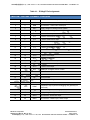
SUNSTAR传感与控制 http://www.sensor-ic.com/ TEL:0755-83376549 FAX:0755-83376182E-MAIL: [email protected]
User Manual
SmartSens
3D MagIC
Sensor Controller ASIC
SUNSTAR自动化 http://www.sensor-ic.com/ TEL: 0755-83376489 FAX:0755-83376182 E-MAIL: [email protected]
SUNSTAR传感与控制 http://www.sensor-ic.com/ TEL:0755-83376549 FAX:0755-83376182E-MAIL: [email protected]
Table of Contents
1
2
3
4
5
6
7
COPYRIGHT & WARRANTY INFORMATION ............................................................ 4
INTRODUCTION .......................................................................................................... 5
SPECIFICATIONS ....................................................................................................... 6
3.1
DEVICE CHARACTERISTICS ........................................................................ 6
3.2
TYPICAL OPERATING CHARACTERISTICS ................................................ 8
3.3
DIMENSIONS AND PACKAGING ................................................................... 9
3.4
SOLDERING ................................................................................................. 12
OVERVIEW AND PIN-OUT........................................................................................ 13
4.1
OVERVIEW ................................................................................................... 13
4.2
IDLE MODE ................................................................................................... 15
4.3
3D MAGIC PINOUT AND CONNECTIONS .................................................. 15
SPI INTERFACE ........................................................................................................ 17
5.1
SPI PINS........................................................................................................ 17
5.1.1 SCLK (Serial Clock Input)................................................................. 17
5.1.2 SSN (Slave Select) ........................................................................... 17
5.1.3 MISO (Serial Out) ............................................................................. 17
5.1.4 MOSI (Serial In) ................................................................................ 17
5.2
HARDWARE HANDSHAKING PINS ............................................................. 18
5.2.1 DRDY (Data Ready) ......................................................................... 18
5.2.2 CLEAR (Clear Command Register) ................................................. 18
5.3
SPI INTERFACE OPERATION ..................................................................... 18
OPERATION – STANDARD MODE .......................................................................... 21
6.1
COMMAND REGISTER ................................................................................ 21
6.1.1 Initiate Sensor Measurement ........................................................... 21
6.1.2 Read/Write to a Cycle Count Register ............................................. 22
6.2
CYCLE COUNT REGISTERS ....................................................................... 22
6.3
MAKING A MEASUREMENT ........................................................................ 23
OPERATION – LEGACY MODE ............................................................................... 25
7.1
COMMAND REGISTER ................................................................................ 25
7.1.1 Initiate Sensor Measurement ........................................................... 25
7.1.2 Read/Write to Clock Set Register ..................................................... 26
7.2
CLOCK SET REGISTER ............................................................................... 27
7.2.1 Clock Divide ...................................................................................... 27
7.2.2 Period Divide .................................................................................... 28
7.3
MAKING A MEASUREMENT ........................................................................ 29
SUNSTAR自动化 http://www.sensor-ic.com/ TEL: 0755-83376489 FAX:0755-83376182 E-MAIL: [email protected]
SUNSTAR传感与控制 http://www.sensor-ic.com/ TEL:0755-83376549 FAX:0755-83376182E-MAIL: [email protected]
List of Figures
Figure 3-1:
Figure 3-2:
Figure 3-3:
Figure 3-4:
Figure 3-5:
Figure 3-6:
Figure 3-7:
Figure 4-1:
Figure 4-2:
Figure 5-1:
Figure 5-2:
Figure 5-3:
Gain vs. Cycle Counts............................................................................................ 8
Maximum Data Rate per Axis vs. Cycle Counts .................................................... 8
3D MagIC MLF Mechanical Drawing ..................................................................... 9
3D MagIC MLF Tape Dimensions ........................................................................ 10
3D MagIC Die Pad Layout ................................................................................... 10
Example Wire Bonding Layout for Legacy 11096 ASIC Applications .................. 11
Recommended Solder Reflow Profile .................................................................. 12
Typical 3D MagIC MLF Application Circuit .......................................................... 13
Biasing Diagram ................................................................................................... 14
SPI Measure/Read Data Timing Diagram – Standard Mode ............................... 19
SPI Measure/Read Data Timing Diagram – Legacy Mode .................................. 19
SPI Read/Write Data Timing ................................................................................ 20
List of Tables
Table 3-1:
Table 3-2:
Table 3-3:
Table 3-4:
Table 4-1:
Table 5-1:
Table 6-1:
Absolute Maximum Ratings .................................................................................... 6
Recommended Operating Conditions ..................................................................... 6
Electrical Characteristics ......................................................................................... 7
Recommended Solder Processing Parameters .................................................... 12
3D MagIC Pin Assignments .................................................................................. 16
Timing Specifications ............................................................................................ 20
Cycle Count Registers........................................................................................... 23
3D MagIC User Manual – May 24, 2010
Page 3 of 29
SUNSTAR自动化 http://www.sensor-ic.com/ TEL: 0755-83376489 FAX:0755-83376182 E-MAIL: [email protected]
SUNSTAR传感与控制 http://www.sensor-ic.com/ TEL:0755-83376549 FAX:0755-83376182E-MAIL: [email protected]
1 Copyright & Warranty Information
© Copyright PNI Sensor Corporation 2010
All Rights Reserved. Reproduction, adaptation, or translation without prior written permission is prohibited, except as allowed under copyright laws.
Revised April 2010: for the most recent version visit our website at www.pnicorp.com
PNI Sensor Corporation
133 Aviation Blvd, Suite 101
Santa Rosa, CA 95403, USA
Tel: (707) 566-2260
Fax: (707) 566-2261
Warranty and Limitation of Liability. PNI Sensor Corporation ("PNI") manufactures its Products from parts and components that are new or
equivalent to new in performance. PNI warrants that each Product to be delivered hereunder, if properly used, will, for ninety (90) days following the
date of shipment unless a different warranty time period for such Product is specified: (i) in PNI’s Price List in effect at time of order acceptance; or (ii)
on PNI’s web site (www.pnicorp.com) at time of order acceptance, be free from defects in material and workmanship and will operate in accordance
with PNI’s published specifications and documentation for the Product in effect at time of order. PNI will make no changes to the specifications or
manufacturing processes that affect form, fit, or function of the Product without written notice to the Customer, however, PNI may at any time, without
such notice, make minor changes to specifications or manufacturing processes that do not affect the form, fit, or function of the Product. This warranty
will be void if the Products’ serial number, or other identification marks have been defaced, damaged, or removed. This warranty does not cover wear
and tear due to normal use, or damage to the Product as the result of improper usage, neglect of care, alteration, accident, or unauthorized repair.
THE ABOVE WARRANTY IS IN LIEU OF ANY OTHER WARRANTY, WHETHER EXPRESS, IMPLIED, OR STATUTORY, INCLUDING, BUT NOT
LIMITED TO, ANY WARRANTY OF MERCHANTABILITY, FITNESS FOR ANY PARTICULAR PURPOSE, OR ANY WARRANTY OTHERWISE
ARISING OUT OF ANY PROPOSAL, SPECIFICATION, OR SAMPLE. PNI NEITHER ASSUMES NOR AUTHORIZES ANY PERSON TO ASSUME
FOR IT ANY OTHER LIABILITY.
If any Product furnished hereunder fails to conform to the above warranty, Customer’s sole and exclusive remedy and PNI’s sole and exclusive liability
will be, at PNI’s option, to repair, replace, or credit Customer’s account with an amount equal to the price paid for any such Product which fails during
the applicable warranty period provided that (i) Customer promptly notifies PNI in writing that such Product is defective and furnishes an explanation of
the deficiency; (ii) such Product is returned to PNI’s service facility at Customer’s risk and expense; and (iii) PNI is satisfied that claimed deficiencies
exist and were not caused by accident, misuse, neglect, alteration, repair, improper installation, or improper testing. If a Product is defective,
transportation charges for the return of the Product to Customer within the United States and Canada will be paid by PNI. For all other locations, the
warranty excludes all costs of shipping, customs clearance, and other related charges. PNI will have a reasonable time to make repairs or to replace
the Product or to credit Customer’s account. PNI warrants any such repaired or replacement Product to be free from defects in material and
workmanship on the same terms as the Product originally purchased.
Except for the breach of warranty remedies set forth herein, or for personal injury, PNI shall have no liability for any indirect or speculative damages
(including, but not limited to, consequential, incidental, punitive and special damages) relating to the use of or inability to use this Product, whether
arising out of contract, negligence, tort, or under any warranty theory, or for infringement of any other party’s intellectual property rights, irrespective of
whether PNI had advance notice of the possibility of any such damages, including, but not limited to, loss of use, revenue or profit. In no event shall
PNI’s total liability for all claims regarding a Product exceed the price paid for the Product. PNI neither assumes nor authorizes any person to assume
for it any other liabilities.
Some states and provinces do not allow limitations on how long an implied warranty lasts or the exclusion or limitation of incidental or consequential
damages, so the above limitations or exclusions may not apply to you. This warranty gives you specific legal rights and you may have other rights that
vary by state or province.
PNI Sensor Corporation
3D MagIC User Manual –May 24, 2010
Pre-Release Version
Page 4 of 29
SUNSTAR自动化 http://www.sensor-ic.com/ TEL: 0755-83376489 FAX:0755-83376182 E-MAIL: [email protected]
SUNSTAR传感与控制 http://www.sensor-ic.com/ TEL:0755-83376549 FAX:0755-83376182E-MAIL: [email protected]
2 Introduction
Thank you for purchasing PNI Sensor Corporation’s SmartSens 3D MagIC. The 3D MagIC is a
control and measurement ASIC for use with PNI’s SmartSens magneto-inductive (MI) sensors
(the Sen-XY and Sen-Z), and represents a dramatic step forward in terms of data rate and
power consumption when compared to PNI’s prior legacy ASIC. It contains drive and
measurement circuitry for interaction with SmartSens sensors, interface circuitry to
communicate with a host microprocessor on an SPI bus, an internal clock and inputs for a usersupplied external clock or crystal oscillator. The 3D MagIC can control and measure three
independent SmartSens sensors. Each SmartSens sensor is individually selectable for
measurement, and can be individually configured for measurement resolution
For most applications the SmartSens MI sensor serves as the inductive element in a simple LR
relaxation oscillation circuit, with its effective inductance proportional to the magnetic field
parallel to the sensor axis. When driven by the 3D MagIC, the frequency of oscillation varies
with the strength of the magnetic field parallel to the sensor.
The output from the 3D MagIC is inherently digital and can be fed directly into a microprocessor,
which eliminates the need for signal conditioning or an analog/digital interface between the
sensor and a microprocessor. The simplicity of the SmartSens circuit combined with the lack of
signal conditioning makes it easier and less expensive to implement than alternative fluxgate or
magneto-resistive (MR) technologies.
Since the SmartSens circuit works in the frequency domain, resolution and noise are
established cleanly by the number of cycle counts. In comparison, fluxgate and MR
technologies require expensive and complex signal processing to obtain similar resolution and
noise, and for certain applications the SmartSens solution cannot be matched.
3D MagIC User Manual – May 24, 2010
Page 5 of 29
SUNSTAR自动化 http://www.sensor-ic.com/ TEL: 0755-83376489 FAX:0755-83376182 E-MAIL: [email protected]
SUNSTAR传感与控制 http://www.sensor-ic.com/ TEL:0755-83376549 FAX:0755-83376182E-MAIL: [email protected]
3 Specifications
3.1 Device Characteristics
Table 3-1: Absolute Maximum Ratings
Parameter
Symbol
Minimum
Maximum
Units
AVDD,
DVDD
-0.3
+3.7
VDC
Input Pin Voltage
VIN
-0.3
AVDD or DVDD
VDC
Input Pin Current @ 25C
IIN
-10.0
+10.0
mA
TSTRG
-40°
+125°
C
Analog/Digital DC Supply
Voltage
Storage Temperature
CAUTION:
Stresses beyond those listed above may cause permanent damage to the device. These are
stress ratings only. Functional operation of the device at these or any other conditions beyond
those indicated in the operational sections of the specifications is not implied. Exposure to
absolute maximum rating conditions for extended periods may affect device reliability.
Table 3-2: Recommended Operating Conditions
Parameter
Analog/Digital DC Supply Voltage
Symbol
Min
Typ
Max
Units
AVDD,
DVDD
1.6
3.3
3.6
VDC
Supply Voltage
Difference
(DVDD-AVDD)
During Operation
∆VDD_OP
-0.1
0
+0.1
VDC
Analog Unpowered
∆VDD_OFF
DVDD-0.1
DVDD
DVDD+0.1
VDC
Bias Resistance
VDD = 3.3 V
Rb
68
Ω
External Timing Resistor for Clock
REXT
33
kΩ
Operating Temperature
TOP
PNI Sensor Corporation
3D MagIC User Manual –May 24, 2010
-40
+85
C
Pre-Release Version
Page 6 of 29
SUNSTAR自动化 http://www.sensor-ic.com/ TEL: 0755-83376489 FAX:0755-83376182 E-MAIL: [email protected]
SUNSTAR传感与控制 http://www.sensor-ic.com/ TEL:0755-83376549 FAX:0755-83376182E-MAIL: [email protected]
Table 3-3: Electrical Characteristics
Parameter
Average Operating Current
Symbol
1,2
Min
IDDM
Typ
Max
0.25
Units
mA
Idle Mode Current
IDDI
1
µA
Leakage Current
IDVDD
100
nA
High level input voltage
VIH
0.7*DVDD
VDD
V
Low level input voltage
VIL
0
0.3*DVDD
V
High level output current
IOH
1
Low level output current
IOL
Sensor Circuit Oscillation
3
Frequency
SCOSC
185
kHz
OSCFREQ
45
MHz
Internal Oscillator Frequency
mA
-1
mA
Note:
1) Bias resistance is to be determined, but expected to be in the range of 50Ω to 70Ω.
2) Polling rate of 8 Hz, cycle count of 1024, and Fast Bias mode.
3) When 3D MagIC is used in conjunction with Sen-XY or Sen-Z sensor and appropriate bias
resistor. Circuit oscillation frequency will vary depending on a number of factors including the
strength of the ambient magnetic field.
3D MagIC User Manual – May 24, 2010
Page 7 of 29
SUNSTAR自动化 http://www.sensor-ic.com/ TEL: 0755-83376489 FAX:0755-83376182 E-MAIL: [email protected]
SUNSTAR传感与控制 http://www.sensor-ic.com/ TEL:0755-83376549 FAX:0755-83376182E-MAIL: [email protected]
3.2 Typical Operating Characteristics
Note that “Cycle Counts” is set by the user through the Cycle Count Registers in Standard
Mode or the Counter Divide (CD) bits in the Legacy Mode’s Clock Set Register.
1000
Standard & Legacy w/ CD=1
Gain (counts/µT)
Legacy w/ CD=16 (default)
100
10
1
10
100
1000
10000
Cycle Counts
Figure 3-1: Gain vs. Cycle Counts
(Resolution = 1/Gain, to the system’s noise limit)
Maximum Data Rate per Axis (Hz)
10000
1000
100
10
1
10
100
1000
10000
Cycle Counts
Figure 3-2: Maximum Data Rate per Axis vs. Cycle Counts
PNI Sensor Corporation
3D MagIC User Manual –May 24, 2010
Pre-Release Version
Page 8 of 29
SUNSTAR自动化 http://www.sensor-ic.com/ TEL: 0755-83376489 FAX:0755-83376182 E-MAIL: [email protected]
SUNSTAR传感与控制 http://www.sensor-ic.com/ TEL:0755-83376549 FAX:0755-83376182E-MAIL: [email protected]
3.3 Dimensions and Packaging
Dimensions in mm.
Figure 3-3: 3D MagIC MLF Mechanical Drawing
3D MagIC User Manual – May 24, 2010
Page 9 of 29
SUNSTAR自动化 http://www.sensor-ic.com/ TEL: 0755-83376489 FAX:0755-83376182 E-MAIL: [email protected]
SUNSTAR传感与控制 http://www.sensor-ic.com/ TEL:0755-83376549 FAX:0755-83376182E-MAIL: [email protected]
Figure 3-4: 3D MagIC MLF Tape Dimensions
Figure 3-5: 3D MagIC Die Pad Layout
PNI Sensor Corporation
3D MagIC User Manual –May 24, 2010
Pre-Release Version
Page 10 of 29
SUNSTAR自动化 http://www.sensor-ic.com/ TEL: 0755-83376489 FAX:0755-83376182 E-MAIL: [email protected]
SUNSTAR传感与控制 http://www.sensor-ic.com/ TEL:0755-83376549 FAX:0755-83376182E-MAIL: [email protected]
Figure 3-6: Example Wire Bonding Layout for Legacy 11096 ASIC Applications
Note that Figure 3-6 is for illustrative purposes only. The sample bond pad layout was taken
from a PNI product. The customer’s bond pad layout will vary, as will the best layout for the
customer’s application.
3D MagIC User Manual – May 24, 2010
Page 11 of 29
SUNSTAR自动化 http://www.sensor-ic.com/ TEL: 0755-83376489 FAX:0755-83376182 E-MAIL: [email protected]
SUNSTAR传感与控制 http://www.sensor-ic.com/ TEL:0755-83376549 FAX:0755-83376182E-MAIL: [email protected]
3.4 Soldering
Table 3-4: Recommended Solder Processing Parameters
Reflow Parameter
Preheat Temperature (Tsmin To Tsmax)
Temperature Tl (Typical Lead-Free Solder
Melting Point)
Temperature (C)
TIME (sec)
150°C – 200°C
60-180
>218°C
Tsmax To Tl Ramp-Up Rate
3°C/Second Max
Peak Temperature Tp
<260°C
Time 25°C To Peak Tp
6 Minute Max
Time Maintained Above Temperature Tl (Tl)
218°C
60-120
Soak (Time Within 5° Of Actual Peak Tp)
Rampdown Rate
10-20
4°C/Second Max
a. Meets IPC/JEDEC J-STD-020 profile recommendations
PB
Figure 3-7: Recommended Solder Reflow Profile
PNI Sensor Corporation
3D MagIC User Manual –May 24, 2010
Pre-Release Version
Page 12 of 29
SUNSTAR自动化 http://www.sensor-ic.com/ TEL: 0755-83376489 FAX:0755-83376182 E-MAIL: [email protected]
SUNSTAR传感与控制 http://www.sensor-ic.com/ TEL:0755-83376549 FAX:0755-83376182E-MAIL: [email protected]
4 Overview and Pin-Out
4.1 Overview
The 3D MagIC contains drive and measurement circuitry for controlling PNI’s SmartSens
magneto-inductive sensors, interface circuitry to communicate with a host microprocessor
on an SPI bus, and an internal clock. It is intended as a component in a SmartSens
magnetic sensing circuit, as show in Figure 4-1, with a detail of the biasing shown in Figure
4-2. The 3D MagIC can be used to interface from one to three sensors depending on
application requirements.
Note: The 3D MagIC typically is used in compassing applications, where each channel represents a
Cartesian coordinate axis (x, y, or z). For this reason, the term “axis” often is used instead of channel
throughout this document.
Figure 4-1: Typical 3D MagIC MLF Application Circuit
3D MagIC User Manual – May 24, 2010
Page 13 of 29
SUNSTAR自动化 http://www.sensor-ic.com/ TEL: 0755-83376489 FAX:0755-83376182 E-MAIL: [email protected]
SUNSTAR传感与控制 http://www.sensor-ic.com/ TEL:0755-83376549 FAX:0755-83376182E-MAIL: [email protected]
Figure 4-2: Biasing Diagram
A single 8 bit command from the host system configures and initiates an axis measurement
from the 3D MagIC. The 3D MagIC can interface with one to three sensors depending on
the application requirement. Unused sensor connections should remain floating. A
magneto-inductive sensor operates in an oscillator circuit composed of an external bias
resistor along with digital gates and a comparator internal to the 3D MagIC. Only one
sensor can be measured at a time. To measure a sensor, a command byte is sent to the 3D
MagIC through the SPI port specifying the axis to be measured. The time to complete a
host-specified number of oscillation cycles is measured in both the forward and reverse bias
directions. The 3D MagIC returns the difference between the two measurement times
represented as a number in a 2’s complement format, and this number is directly
proportional to the direction and strength of the local magnetic field.
The 3D MagIC’s output provides the difference in the high-speed oscillator cycles between
the forward-biased and reverse-biased sensor measurements. To make a measurement,
one side of the sensor is grounded while the other side is alternately driven with positive and
negative current through the oscillator. The number of circuit oscillations (cycle counts) is
user-defined in software and establishes how many oscillations of the RL circuit are desired
per measurement. The greater the cycle counts, the higher the resolution of the
measurement and the longer the sample time. The high-speed oscillator measures how
long it takes to make the desired number cycle counts. The 3D MagIC next switches the
bias connection to the sensor and makes another measurement. The side that was
previously grounded is now charged and discharged while the other is now grounded.
PNI Sensor Corporation
3D MagIC User Manual –May 24, 2010
Pre-Release Version
Page 14 of 29
SUNSTAR自动化 http://www.sensor-ic.com/ TEL: 0755-83376489 FAX:0755-83376182 E-MAIL: [email protected]
SUNSTAR传感与控制 http://www.sensor-ic.com/ TEL:0755-83376549 FAX:0755-83376182E-MAIL: [email protected]
4.2 Idle Mode
The 3D MagIC incorporates an Idle Mode to reduce power consumption, in which it
automatically idles when it is not exchanging data or taking a measurement. Unlike the
legacy 11096 ASIC, the 3D MagIC starts in the Idle Mode at power-up and remains in Idle
Mode until a measurement is needed. Therefore, it is not necessary to cycle the 3D MagIC
through one measurement request operation to ensure it is in Idle Mode, as was required by
the legacy 11096 ASIC.
4.3 3D MagIC Pinout and Connections
The 3D MagIC’s pinout is summarized in Table 4-1. Pin numbers run counterclockwise
(when looking from the top), starting at the Pin 1 designator as shown in Figure 3-3.
3D MagIC User Manual – May 24, 2010
Page 15 of 29
SUNSTAR自动化 http://www.sensor-ic.com/ TEL: 0755-83376489 FAX:0755-83376182 E-MAIL: [email protected]
SUNSTAR传感与控制 http://www.sensor-ic.com/ TEL:0755-83376549 FAX:0755-83376182E-MAIL: [email protected]
Table 4-1: 3D MagIC Pin Assignments
MLF Pin#
Die Pad#
Pin Name Description
1
1
MOSI
2
2
NC
3
3
SSN
SPI interface – Active low to select port
4
4
AVDD
Supply voltage for analog section of ASIC
5
5
AVSS
Ground pin for analog section of ASIC
6
6
ZDRVP
Z sensor drive output
7
7
ZINP
Z sensor measurement input
8
8
ZINN
Z sensor measurement input
9
9
ZDRVN
Z sensor drive output
10
10
YDRVP
Y sensor drive output
11
11
YINP
12
12
MODE
13
13
YINN
14
14
YDRVN
Y sensor drive output
15
15
XDRVP
X sensor drive output
16
16
XINP
X sensor measurement input
17
17
XINN
X sensor measurement input
18
18
XDRVN
X sensor drive output
19
19
DVSS
Ground pin for digital section of ASIC
--
20
NC
Do not connect
20
21
NC
Do not connect
21
22
NC
Do not connect
22
23
CLEAR
Clear Command Register
23
24
DRDY
Data ready command
24
25
COMP
Comparator output (used for debugging and generally not
connected)
25
26
REXT
External timing resistor for high speed clock.
26
27
DVDD
Supply voltage for digital section of ASIC.
27
28
SCLK
SPI interface - Serial clock input
28
29
MISO
SPI interface – Master Input, Slave Output
PNI Sensor Corporation
3D MagIC User Manual –May 24, 2010
SPI interface – Master Output, Slave Input Serial Data
Do not connect
Y sensor measurement input
Mode Select: tie to DVSS for Standard, DVDD for Legacy
Y sensor measurement input
Pre-Release Version
Page 16 of 29
SUNSTAR自动化 http://www.sensor-ic.com/ TEL: 0755-83376489 FAX:0755-83376182 E-MAIL: [email protected]
SUNSTAR传感与控制 http://www.sensor-ic.com/ TEL:0755-83376549 FAX:0755-83376182E-MAIL: [email protected]
5 SPI Interface
Data flow to and from the 3D MagIC is through a synchronous serial interface that adheres to
the SPI bus protocol. The user also may implement hardware handshaking, but this is optional.
This section reviews the SPI interface and hardware handshaking.
5.1 SPI Pins
5.1.1 SCLK (Serial Clock Input)
An SPI input is used to synchronize the data sent in and out through the MISO and
MOSI pins. SCLK is generated by the customer-supplied master device and should be 1
MHz or less. One byte of data is exchanged over eight clock cycles. Data is captured
by the master device on the rising edge of SCLK. Data is shifted out and presented to
the 3D MagIC on the MOSI pin on the falling edge of SCLK.
5.1.2 SSN (Slave Select)
This signal sets the 3D MagIC as the operating slave device on the SPI bus. The SSN
pin must be LOW prior to data transfer in either direction, and must stay LOW during the
entire transfer. The SPI bus can be freed up (SSN pin set HIGH) for communication with
another slave device while the 3D MagIC is taking a measurement or idle, but after all
communication between the 3D MagIC and master device is finished. If the 3D MagIC is
the only device on the SPI bus, this pin may be permanently grounded.
5.1.3 MISO (Serial Out)
An SPI output that sends data from the 3D MagIC to the master device. Data is
transferred most significant bit first and is captured by the master device on the rising
edge of SCLK. The MISO pin is placed in a high impedance state if the 3D MagIC is not
selected (i.e. if SSN=1).
5.1.4 MOSI (Serial In)
An SPI input that provides data from the master device to the 3D MagIC. Data is
transferred most significant bit first. Data must be presented at least 50 ns before the
rising edge of SCLK, and remain valid for 50 ns after the edge. New data may be
presented to the MOSI pin on the falling edge of SCLK.
3D MagIC User Manual – May 24, 2010
Page 17 of 29
SUNSTAR自动化 http://www.sensor-ic.com/ TEL: 0755-83376489 FAX:0755-83376182 E-MAIL: [email protected]
SUNSTAR传感与控制 http://www.sensor-ic.com/ TEL:0755-83376549 FAX:0755-83376182E-MAIL: [email protected]
5.2 Hardware Handshaking Pins
5.2.1 DRDY (Data Ready)
It is recommended the DRDY pin be used to ensure data is read out of the 3D MagIC
only when it is available. After the Initiate Sensor Measurement command has been
sent, the DRDY pin will go HIGH when the measurement is complete. This signals the
host system that data is ready to be read. The DRDY pin should be set LOW sometime
prior to initiating another measurement. This is done by clearing the Command Register
by either of the following actions:
•
externally, by toggling the CLEAR pin, or
•
internally, after reading or writing to the Clock Set Register.
Note: If a new command sequence is started before the previous measurement has completed
(before DRDY goes HIGH), the previous command will be overwritten. This will also stop the
measurement cycle. If you try to send a new command during the readout phase, after DRDY
goes HIGH, the command will be ignored until all 16 bits have been clocked our or the CLEAR
pin is set HIGH (then LOW again).
5.2.2 CLEAR (Clear Command Register)
To initiate a clear command, the CLEAR pin must be toggled LOW-HIGH-LOW. CLEAR
is usually LOW. A CLEAR will clear the Command Register and reset the DRDY pin to
LOW. CLEAR can be used to stop any sensor measurement in progress. CLEAR has
no effect on the SPI register state.
Note: The CLEAR pin is similar to the RESET pin on PNI’s legacy ASIC. However reading or
writing to the Clock Set Register also will clear the Command Register. Consequently, it is not
necessary to utilize the CLEAR pin if the host system will read or write to the Clock Set Register
to clear the Command Register.
5.3 SPI Interface Operation
When implementing an SPI port, whether a dedicated hardware peripheral port or a
software-implemented port using general purpose I/O (also known as Bit-Banging), the
timing parameters (given in Figure 5-1, Figure 5-2, and Figure 5-3) must be met to
ensure reliable communications. When SCLK is LOW, the data is in transition. The
clock set-up and hold times, tDBSH and tDASH must be greater than 50 ns. The clock
phase used with the 3D MagIC is zero (CPOL=0). Data is present on MISO or should be
presented on MOSI before the first low to high clock transition.
PNI Sensor Corporation
3D MagIC User Manual –May 24, 2010
Pre-Release Version
Page 18 of 29
SUNSTAR自动化 http://www.sensor-ic.com/ TEL: 0755-83376489 FAX:0755-83376182 E-MAIL: [email protected]
SUNSTAR传感与控制 http://www.sensor-ic.com/ TEL:0755-83376549 FAX:0755-83376182E-MAIL: [email protected]
`
Figure 5-1: SPI Measure/Read Data Timing Diagram – Standard Mode
tSHDZ
Start Measurement and Read Measure Data
tsc
SSN can go HIGH between measurement
command and data read segments
SSN
tCMIN
CLEAR
tSSDV
SCLK
MOSI
RFLAG
=0
tDBSH
tDASH
6
5
4
3
2
1
LSB
COMMAND BYTE
MSB
MISO
14
13
12
2
1
LSB
COMMAND CYCLE RETURN BYTE = 0x9B
DRDY
Figure 5-2: SPI Measure/Read Data Timing Diagram – Legacy Mode
3D MagIC User Manual – May 24, 2010
Page 19 of 29
SUNSTAR自动化 http://www.sensor-ic.com/ TEL: 0755-83376489 FAX:0755-83376182 E-MAIL: [email protected]
SUNSTAR传感与控制 http://www.sensor-ic.com/ TEL:0755-83376549 FAX:0755-83376182E-MAIL: [email protected]
Figure 5-3: SPI Read/Write Data Timing
Table 5-1: Timing Specifications
SYMBOL
DESCRIPTION
MIN
TYP
MAX
UNITS
tSC
Time from SSN to CLEAR
10
ns
tCMIN
CLEAR duration
100
ns
tSSDV
Time from SSN to Command Byte on MOSI
1
us
tDBSH
Time to setup data before active edge
50
ns
tDASH
Time to setup data after active edge
50
ns
tSHDZ
Time from SSN to data tri-state time
100
ns
Note that an SPI port can be implemented using different clock polarity options. The clock
polarity used with the 3D MagIC should be low (CPOL=0). Generally data is considered
valid while SCLK is high, and when SCLK is low, data is in transition.
As previously noted, keeping the SSN pin LOW dedicates the master device to the 3D
MagIC. If the user has no other slave devices, the SSN pin can be permanently grounded.
Conversely, if the user has multiple slave devices, then the SPI bus can be freed up for
other devices by bringing the SSN pin HIGH. The SSN pin can be brought HIGH either:
•
after sending the command word on the MOSI pin but before reading the
measurement data on the MISO pin, and/or
•
after receiving the measurement data on the MISO pin.
PNI Sensor Corporation
3D MagIC User Manual –May 24, 2010
Pre-Release Version
Page 20 of 29
SUNSTAR自动化 http://www.sensor-ic.com/ TEL: 0755-83376489 FAX:0755-83376182 E-MAIL: [email protected]
SUNSTAR传感与控制 http://www.sensor-ic.com/ TEL:0755-83376549 FAX:0755-83376182E-MAIL: [email protected]
6 Operation – Standard Mode
The 3D MagIC operates in Standard Mode when pin #12 is held LOW (grounded to DVSS). This
section discusses how to operate the 3D MagIC in Standard Mode. For a description of
operation in Legacy Mode, see Section 7.
6.1 Command Register
The Command Register can be used either to initiate a sensor measurement or to
read/write to the Cycle Count Registers. It consists of one byte. Bit 7 is the Register
Access Flag (RFLAG), and this controls whether a sensor measurement will be initiated
or a read/write to a register will be initiated. The setting of bits 0-6 depends on how
RFLAG is set.
6.1.1 Initiate Sensor Measurement
The Command Byte is defined as follows:
7
6
5
RFLAG=0
0
0
4
3
2
1
0
CMPO ODIR MOT AS1 AS0
CMPO: Comparator Output
When set HIGH, this enables comparator output on the COMP pin.
ODIR: Oscillator Direction
Determines the magnetic oscillator direction if MOT is set HIGH. If MOT is set LOW,
ODIR has no effect. Used for debug only.
MOT: Magnetic Oscillator Test
When set HIGH, causes the sensor oscillator selected by AS0 and AS1 (in the
direction selected by ODIR) to run continuously. The COMP pin output is always
enabled when MOT is HIGH. When the MOT bit is set HIGH, the data read segment
is not supported and a new command can be received immediately. MOT mode can
be exited by sending a measurement command, by setting CLEAR to HIGH, or by
receiving a NO OP command (AS0=AS1=0).
AS0-AS1: Axis Select
Determines the sensor to be measured.
3D MagIC User Manual – May 24, 2010
Page 21 of 29
SUNSTAR自动化 http://www.sensor-ic.com/ TEL: 0755-83376489 FAX:0755-83376182 E-MAIL: [email protected]
SUNSTAR传感与控制 http://www.sensor-ic.com/ TEL:0755-83376549 FAX:0755-83376182E-MAIL: [email protected]
AS1
AS0
No Op: see note
0
0
Channel 1 (X axis)
0
1
Channel 2 (Y axis)
1
0
Channel 3 (Z axis)
1
1
Note: If no measurement is executed, then the previous measurement will be read
back if data is clocked out.
6.1.2 Read/Write to a Cycle Count Register
The Command Byte is defined as follows:
7
6
RFLAG=1 R/W
5
4
0
0
3
2
1
0
ADR3 ADR2 ADR1 ADR0
R/W: Read/Write
HIGH signifies a Read operation from the addressed register. LOW signifies a Write
operation to the addressed register.
ADR0 – ADR3: Register Address Bits
Establishes which register will be written to or read from. When adjacent registers
are to be addressed, which is typically is the case, it is not necessary to reinitiate the
command sequence as the 3D MagIC automatically will read/write to the next
adjacent register. (See the example in the following section.)
6.2 Cycle Count Registers
The Cycle Count Registers establish the number of sensor oscillations cycles that will be
counted for each sensor during a measurement sequence. Varying the cycle count allows
the user to increase measurement resolution (higher cycle counts) or increase the data rate
(lower cycle counts). Each sensor is represented by two registers, with addresses defined
as follows:
PNI Sensor Corporation
3D MagIC User Manual –May 24, 2010
Pre-Release Version
Page 22 of 29
SUNSTAR自动化 http://www.sensor-ic.com/ TEL: 0755-83376489 FAX:0755-83376182 E-MAIL: [email protected]
SUNSTAR传感与控制 http://www.sensor-ic.com/ TEL:0755-83376549 FAX:0755-83376182E-MAIL: [email protected]
Table 6-1: Cycle Count Registers
REGISTER
NAME
DESCRIPTION
REGISTER
ADDRESS
CCPX1
X Axis Cycle Count Value - MSB
3H
CCPX0
X Axis Cycle Count Value - LSB
4H
CCPY1
Y Axis Cycle Count Value - MSB
5H
CCPY0
Y Axis Cycle Count Value - LSB
6H
CCPZ1
Z Axis Cycle Count Value - MSB
7H
CCPZ0
Z Axis Cycle Count Value - LSB
8H
An example of a command sequence to set the cycle count value to 100D (64H) for all 3 axes
is as follows. Note that since the registers are adjacent, it is not necessary to send multiple
Command Register commands, as the 3D MagIC will automatically read/write to the next
adjacent register.
1. Set SSN to LOW
2. Send 0x83H (this is the Command Register byte & addresses the MSB for the X axis)
3. Send 0 (this is the MSB for the X axis)
4. Send 0x64H (this is the LSB for the X axis)
5. Send 0 (this is the MSB for the Y axis)
6. Send 0x64H (this is the LSB for the Y axis)
7. Send 0 (this is the MSB for the Z axis)
8. Send 0x64H (this is the LSB for the Z axis)
9. Set SSN to High
The default for all three axes is a cycle count value of 512D (LSB = 0H, MSB = 20H).
6.3 Making a Measurement
The steps to make a sensor measurement are given below, and the sequence and timing
are given in Figure 5-1 and Figure 5-3. In general, the user sends an Initiate Sensor
Measurement command to the 3D MagIC through the SPI interface specifying the sensor to
be measured. The Cycle Count Registers should already be set prior to sending this
command (or the default values will be used). In Standard Mode, the 3D MagIC returns the
result of a complete forward- reverse measurement of the sensor in a 24 bit 2’s complement
3D MagIC User Manual – May 24, 2010
Page 23 of 29
SUNSTAR自动化 http://www.sensor-ic.com/ TEL: 0755-83376489 FAX:0755-83376182 E-MAIL: [email protected]
SUNSTAR传感与控制 http://www.sensor-ic.com/ TEL:0755-83376549 FAX:0755-83376182E-MAIL: [email protected]
format (range: -8388608 to 8388607). Note that only one sensor can be measured at a
time.
1. SSN pin is set LOW. This enables communication with the master device.
2. The Initiate Sensor Measurement byte is clocked into the 3D MagIC on the MOSI
pin. Simultaneously, the 3D MagIC will present a fixed 0x9A on the MISO pin. Once
the 8 bits have clocked in, the 3D MagIC will execute the command (i.e. take a
measurement).
3. The SSN input may be returned HIGH at this point to free up host communication
with another device if desired. This will not affect the measurement process.
4. A measurement is taken, which consists of forward biasing the sensor and
measuring how long it takes to accomplish the pre-defined number of cycle counts;
then reverse biasing the sensor and measuring again; and then taking the difference
in time between the two directions and presenting this value.
5. At the end of the measurement, the DRDY pin is set HIGH, indicating data is ready,
and the 3D MagIC is placed in Idle Mode.
6. The SSN input should be set LOW, if it is not already, to read the data.
7. The data is clocked out on the MISO pin with the next 24 clock cycles.
8. If another measurement is to be made immediately, the SSN pin can remain low and
the process repeated, starting at line #2 above. Otherwise, it generally is
recommended to set the SSN pin HIGH to release the SPI serial bus.
PNI Sensor Corporation
3D MagIC User Manual –May 24, 2010
Pre-Release Version
Page 24 of 29
SUNSTAR自动化 http://www.sensor-ic.com/ TEL: 0755-83376489 FAX:0755-83376182 E-MAIL: [email protected]
SUNSTAR传感与控制 http://www.sensor-ic.com/ TEL:0755-83376549 FAX:0755-83376182E-MAIL: [email protected]
7 Operation – Legacy Mode
The 3D MagIC will operate in Legacy Mode when pin #12 is held HIGH (connected to DVDD).
The intent of Legacy Mode is to enable the user to easily substitute PNI’s 3D MagIC for PNI’s
legacy 11096 ASIC (p/n 12576). This section discusses how to operate the 3D MagIC in
Legacy Mode. For a description of operation in Standard Mode, see Section 6.
7.1 Command Register
The Command Register can be used either to initiate a sensor measurement or set-up a
read/write to the Clock Set Register. It consists of one byte. Bit 7 is the Register Access
Flag (RFLAG), and this controls whether a sensor measurement will be initiated or a
read/write to the Clock Set Register will be initiated. The setting of bits 0-6 depends on
how RFLAG is set.
7.1.1 Initiate Sensor Measurement
The Command Register is defined as follows:
7
6
5
4
3
2
1
0
RFLAG=0 PS2 PS1 PS0 ODIR MOT AS1 AS0
PS0-PS2: Period Select
Selects the number of sensor circuit oscillation cycles (periods) to be counted while
simultaneously using the internal fixed reference clock to measure the time to obtain
this count.
Period Select
Value
Cycle
Counts
PS2
PS1
PS0
0
32
0
0
0
1
64
0
0
1
2
128
0
1
0
3
256
0
1
1
4
512
1
0
0
5
1024
1
0
1
6
2048
1
1
0
7
4096
1
1
1
3D MagIC User Manual – May 24, 2010
Page 25 of 29
SUNSTAR自动化 http://www.sensor-ic.com/ TEL: 0755-83376489 FAX:0755-83376182 E-MAIL: [email protected]
SUNSTAR传感与控制 http://www.sensor-ic.com/ TEL:0755-83376549 FAX:0755-83376182E-MAIL: [email protected]
ODIR: Oscillator Direction
Determines the magnetic oscillator direction if MOT is set HIGH. If MOT is set LOW,
ODIR has no effect. Used for debug only.
MOT: Magnetic Oscillator Test
When set HIGH, causes the sensor oscillator selected by AS0 and AS1 (in the
direction selected by ODIR) to run continuously. The COMP pin output is always
enabled when MOT is HIGH. When the MOT bit is set HIGH, the data read segment
is not supported and a new command can be received immediately. MOT mode can
be exited by sending a measurement command, by setting CLEAR to HIGH, or by
receiving a NO OP command (AS0=AS1=0).
AS0-AS1: Axis Select
Determines the sensor to be measured.
AS1
AS0
No Op: see note
0
0
Channel 1 (X axis)
0
1
Channel 2 (Y axis)
1
0
Channel 3 (Z axis)
1
1
Note: No measurement will be executed, and the previous measurement will be
read back if data is clocked out.
7.1.2 Read/Write to Clock Set Register
The Command Register is defined as follows:
7
6
RFLAG=1 R/W
5
4
3
2
1
0
0
0
0
0
0
0
Bits 0-5 must be set LOW when RFLAG = 1.
R/W: Read/Write
When HIGH signifies a Read operation from the Clock Set Register. When LOW
signifies a Write operation to the Clock Set Register.
PNI Sensor Corporation
3D MagIC User Manual –May 24, 2010
Pre-Release Version
Page 26 of 29
SUNSTAR自动化 http://www.sensor-ic.com/ TEL: 0755-83376489 FAX:0755-83376182 E-MAIL: [email protected]
SUNSTAR传感与控制 http://www.sensor-ic.com/ TEL:0755-83376549 FAX:0755-83376182E-MAIL: [email protected]
7.2 Clock Set Register
Note: If a user incorporates the 3D MagIC in a legacy 11096 ASIC system and uses the same Period
Select value, and leaves the Counter Divide and Period Dividevalues at their default values, then the
3D MagIC will provide approximately the same resolution as PNI’s legacy ASIC at the same data
rate.
The Clock Set Register commands allow the user to operate the 3D MagIC in Legacy Mode
similar to PNI’s legacy ASIC, but derive some of the benefits available with the 3D MagIC.
Specifically, due to the higher clock speed (30 MHz vs 2 MHz) of the MagIC, it is capable of
providing either higher resolution for the same acquisition time (data rate) or comparable
resolution for a shorter acquisition time. This is done by varying the Clock Divide and Period
Divide values in the Clock Set Register. And, since power consumption is directly correlated
to acquisition time, this means an existing system can run with lower power consumption
while retaining comparable resolution.
Specifically, setting the Clock Divide to 1 and making no other changes provides a
theoretical increase in resolution of 16x, without altering the data rate. Alternatively, setting
the Clock Divide to 1 and setting the Period Divide to 16 provides nominally the same
resolution, but at 1/16th the acquisition time, which is useful for high speed applications
and/or applications that are sensitive to power consumption.
The Command Register is defined as follows:
7
0
6
5
4
PCS2 PCS1 PCS0
3
0
2
1
0
CD2 CD1 CD0
7.2.1 Clock Divide
The 3D MagIC’s high-speed clock runs at nominally 32 MHz, but PNI’s legacy ASIC runs
at nominally 2 MHz. Consequently, when the 3d MagIC is in default Legacy Mode, the
clock speed is divided by 16, to bring it down to an effective clock speed of 2 MHz (same
as the legacy 11096 ASIC.) The Clock Divide bits allow the user to alter the divisor for
the high speed clock. Setting the Clock Divide bits all to “0” results in high speed clock
operating at its full speed. Below is a table that summarized the clock divide values for
given Clock Divide bits.
3D MagIC User Manual – May 24, 2010
Page 27 of 29
SUNSTAR自动化 http://www.sensor-ic.com/ TEL: 0755-83376489 FAX:0755-83376182 E-MAIL: [email protected]
SUNSTAR传感与控制 http://www.sensor-ic.com/ TEL:0755-83376549 FAX:0755-83376182E-MAIL: [email protected]
Clock Divide Value
CD2
CD1
CD0
1
0
0
0
2
0
0
1
4
0
1
0
8
0
1
1
16
1
0
0
16
1
0
1
16
1
1
0
16
1
1
1
7.2.2 Period Divide
The Period Divide divides the Period Select value by the Period Divide value. The
default is 1, which leaves the number of cycle counts to be counted unchanged.
PCS Value
PCS2
PCS1
PCS0
1
0
0
0
2
0
0
1
4
0
1
0
8
0
1
1
16
1
0
0
16
1
0
1
16
1
1
0
16
1
1
1
The Period Divide can be used to run the 3D MagIC at fewer cycles than allowed by the
Period Select. For example, a Period Select value of 0 dictates that 32 cycles will be
counted. By setting the Period Divide value to 16, the number of cycles is reduced to 2
cycles, which represents the fewest number of cycles possible with the 3D MagIC.
(Fundamental resolution also will have decreased by a factor of 16 by doing this.) This
can be very useful for high-speed applications, such as video gaming, that require
frequent data updates.
PNI Sensor Corporation
3D MagIC User Manual –May 24, 2010
Pre-Release Version
Page 28 of 29
SUNSTAR自动化 http://www.sensor-ic.com/ TEL: 0755-83376489 FAX:0755-83376182 E-MAIL: [email protected]
SUNSTAR传感与控制 http://www.sensor-ic.com/ TEL:0755-83376549 FAX:0755-83376182E-MAIL: [email protected]
7.3 Making a Measurement
The steps to make a sensor measurement are given below, and the sequence and timing
are given in Figure 5-3 and Figure 5-3. In general, the user sends an Initiate Sensor
Measurement command to the 3D MagIC through the SPI interface specifying the sensor to
be measured and the Period Select. If the user wants to alter the Counter Divide or Period
Divide, they should do this separately by sending a command to the Clock Set Register. I
Legacy Mode, the 3D MagIC returns the result of a complete forward- reverse measurement
of the sensor in a 16 bit 2’s complement format (range: -32768 to 32767). Note that only
one sensor can be measured at a time, and that .
1. SSN pin is set LOW. (This enables communication with the master device.)
2. CLEAR pin is set HIGH, then LOW. This is not required, but is optional to
maintain compatibility with the legacy 11096 ASIC.
3. A command byte is clocked into the 3D MagIC on the MOSI pin. Simultaneously,
the 3D MagIC will present a fixed 0x9B on the MISO pin. Once the 8 bits have
clocked in, the 3D MagIC will execute the command (i.e. take a measurement).
4. The SSN input may be returned HIGH at this point to free up host communication
with another device if desired. This will not affect the measurement process.
5. A measurement is taken, which consists of forward biasing the sensor and
making a period count; then reverse biasing the sensor and counting again; and
then taking the difference between the two directions and presenting this value.
6. At the end of the measurement, the DRDY pin is set HIGH, indicating data is
ready, and the 3D MagIC is placed in Idle Mode.
7. The SSN input should be set LOW, if it is not already, to read the data.
8. The data is clocked out on the MISO pin with the next 16 clock cycles.
9. If another measurement is to be made immediately, the SSN pin can remain low
and the process repeated. Otherwise, it generally is recommended to set the
SSN pin HIGH to release the SPI serial bus.
3D MagIC User Manual – May 24, 2010
Page 29 of 29
SUNSTAR自动化 http://www.sensor-ic.com/ TEL: 0755-83376489 FAX:0755-83376182 E-MAIL: [email protected]